WO2021177032A1 - 射出成形機、射出成形機システム、監視装置 - Google Patents
射出成形機、射出成形機システム、監視装置 Download PDFInfo
- Publication number
- WO2021177032A1 WO2021177032A1 PCT/JP2021/005904 JP2021005904W WO2021177032A1 WO 2021177032 A1 WO2021177032 A1 WO 2021177032A1 JP 2021005904 W JP2021005904 W JP 2021005904W WO 2021177032 A1 WO2021177032 A1 WO 2021177032A1
- Authority
- WO
- WIPO (PCT)
- Prior art keywords
- injection molding
- molding machine
- fpga
- cpu
- mode
- Prior art date
- Legal status (The legal status is an assumption and is not a legal conclusion. Google has not performed a legal analysis and makes no representation as to the accuracy of the status listed.)
- Ceased
Links
Images


Classifications
-
- G—PHYSICS
- G06—COMPUTING OR CALCULATING; COUNTING
- G06F—ELECTRIC DIGITAL DATA PROCESSING
- G06F9/00—Arrangements for program control, e.g. control units
- G06F9/06—Arrangements for program control, e.g. control units using stored programs, i.e. using an internal store of processing equipment to receive or retain programs
- G06F9/44—Arrangements for executing specific programs
- G06F9/4401—Bootstrapping
-
- B—PERFORMING OPERATIONS; TRANSPORTING
- B29—WORKING OF PLASTICS; WORKING OF SUBSTANCES IN A PLASTIC STATE IN GENERAL
- B29C—SHAPING OR JOINING OF PLASTICS; SHAPING OF MATERIAL IN A PLASTIC STATE, NOT OTHERWISE PROVIDED FOR; AFTER-TREATMENT OF THE SHAPED PRODUCTS, e.g. REPAIRING
- B29C45/00—Injection moulding, i.e. forcing the required volume of moulding material through a nozzle into a closed mould; Apparatus therefor
- B29C45/17—Component parts, details or accessories; Auxiliary operations
- B29C45/84—Safety devices
-
- B—PERFORMING OPERATIONS; TRANSPORTING
- B29—WORKING OF PLASTICS; WORKING OF SUBSTANCES IN A PLASTIC STATE IN GENERAL
- B29C—SHAPING OR JOINING OF PLASTICS; SHAPING OF MATERIAL IN A PLASTIC STATE, NOT OTHERWISE PROVIDED FOR; AFTER-TREATMENT OF THE SHAPED PRODUCTS, e.g. REPAIRING
- B29C45/00—Injection moulding, i.e. forcing the required volume of moulding material through a nozzle into a closed mould; Apparatus therefor
- B29C45/17—Component parts, details or accessories; Auxiliary operations
- B29C45/76—Measuring, controlling or regulating
- B29C45/768—Detecting defective moulding conditions
-
- B—PERFORMING OPERATIONS; TRANSPORTING
- B29—WORKING OF PLASTICS; WORKING OF SUBSTANCES IN A PLASTIC STATE IN GENERAL
- B29C—SHAPING OR JOINING OF PLASTICS; SHAPING OF MATERIAL IN A PLASTIC STATE, NOT OTHERWISE PROVIDED FOR; AFTER-TREATMENT OF THE SHAPED PRODUCTS, e.g. REPAIRING
- B29C2945/00—Indexing scheme relating to injection moulding, i.e. forcing the required volume of moulding material through a nozzle into a closed mould
- B29C2945/76—Measuring, controlling or regulating
- B29C2945/76003—Measured parameter
- B29C2945/76163—Errors, malfunctioning
Definitions
- This disclosure relates to injection molding machines, etc.
- Patent Document a technique is disclosed in which, when an injection molding machine is stopped in an abnormal state, the injection molding machine is started in a limited start mode in which the functions are limited compared to the normal start mode at the next start.
- the user can go to the injection molding machine to start the injection molding machine, or the injection molding machine can be remotely controlled through an external device. It is necessary to perform remote control to activate. Therefore, it is desirable that the injection molding machine can be automatically restored when an abnormality occurs in the injection molding machine.
- Information processing department and A monitoring unit provided separately from the information processing unit and monitoring an abnormality in the information processing unit is provided.
- the monitoring unit automatically restarts the information processing unit in a predetermined activation mode having more limited functions than the normal activation mode.
- An injection molding machine is provided.
- Injection molding machine and A monitoring device provided outside the injection molding machine and monitoring an abnormality of the injection molding machine is provided.
- the monitoring device automatically restarts the injection molding machine in a predetermined start mode having more limited functions than the normal start mode.
- An injection molding machine system is provided.
- the injection molding machine is communicably connected to the injection molding machine, and when an abnormality occurs in the injection molding machine, the injection molding machine is automatically restarted in a predetermined start mode having more limited functions than the normal start mode.
- a monitoring device is provided.
- the injection molding machine can be automatically restored when an abnormality occurs in the injection molding machine.
- management system an injection molding machine management system (hereinafter, simply “management system”) SYS (an example of an injection molding machine system) according to the present embodiment will be described.
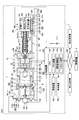
- FIG. 1 and 2 are diagrams showing an example of the management system SYS according to the present embodiment.
- FIG. 1 is a side sectional view showing a state of the injection molding machine 1 at the time of mold opening
- FIG. 2 is a side sectional view showing a state of the injection molding machine 1 at the time of mold clamping.
- the X-axis, the Y-axis, and the Z-axis are perpendicular to each other, and the positive-negative direction of the X-axis (hereinafter, simply "X-direction") and the positive-negative direction of the Y-axis (hereinafter, simply "”.
- the "Y direction”) represents the horizontal direction
- the positive / negative direction of the Z axis hereinafter, simply "Z direction” represents the vertical direction.
- the management system SYS includes a plurality of (three in this example) injection molding machines 1 and a management device 2.
- the management system SYS manages (monitors) the state, operating status, etc. of the injection molding machine 1 in the management device 2.
- the management device 2 and the injection molding machine 1 may be operated by the same person as a whole.
- the management device 2 and the injection molding machine 1 may be operated together by, for example, a person (company) who owns a factory in which the injection molding machine 1 is installed.
- the management device 2 and the injection molding machine 1 may be operated by different persons.
- the management device 2 may be operated by the manufacturer of the injection molding machine 1 that delivers the injection molding machine 1 to the factory. That is, the manufacturer of the injection molding machine 1 may provide not only the injection molding machine 1 but also the management service of the injection molding machine 1 through the management device 2 to the customer (factory owner).
- the management device 2 may be operated by a third party (consignment company) who is entrusted with the management of the injection molding machine 1 by the owner (company) of the factory where the injection molding machine 1 is installed. That is, the management service of the injection molding machine 1 through the management device 2 may be provided to the owner of the factory by a consignment company different from the manufacturer of the injection molding machine 1.
- a third party agreement company
- the management service of the injection molding machine 1 through the management device 2 may be provided to the owner of the factory by a consignment company different from the manufacturer of the injection molding machine 1.
- the number of injection molding machines 1 included in the management system SYS may be one or two, or four or more. Further, the number of management devices 2 included in the management system SYS may be plural. In this case, for example, the plurality of management devices 2 may each manage a part of the injection molding machines 1 among all the injection molding machines 1 included in the management system SYS.
- the injection molding machine 1 performs a series of operations for obtaining a molded product.
- the injection molding machine 1 is communicably connected to the management device 2 through a predetermined communication line NW. Further, the injection molding machine 1 may be communicably connected to another injection molding machine 1 through the communication line NW.
- the communication line NW includes, for example, a local area network (LAN) in the factory where the injection molding machine 1 is installed.
- the local network may be wired, wireless, or both.
- the communication line NW may include, for example, a wide area network (WAN: Wide Area Network) outside the factory where the injection molding machine 1 is installed.
- the wide area network may include, for example, a mobile communication network having a base station as an end.
- Mobile communication network for example, LTE may correspond to (Long Term Evolution) including 4G (4 th Generation) and 5G (5 th Generation) and the like.
- the wide area network may include, for example, a satellite communication network that uses a communication satellite. Further, the wide area network may include, for example, an Internet network. Further, the communication line NW may be, for example, a short-range wireless communication line corresponding to Bluetooth (registered trademark) communication, WiFi communication, or the like.
- the injection molding machine 1 transmits (uploads) data related to the operating state of the injection molding machine 1 (hereinafter, “operating state data”) to the management device 2 through the communication line NW.
- operating state data data related to the operating state of the injection molding machine 1
- the management device 2 or its manager, worker, etc.
- the management device 2 can grasp the operating state and manage the maintenance timing of the injection molding machine 1, the operation schedule of the injection molding machine 1, and the like.
- the management device 2 generates data related to the control of the injection molding machine 1 (for example, molding conditions, etc.) based on the operating state data of the injection molding machine 1, and transmits the data to the injection molding machine 1 to inject from the outside. It is possible to control the molding machine 1.
- the injection molding machine 1 may monitor or control the operation of another injection molding machine 1 as a slave machine as a master machine through a communication line NW.
- the injection molding machine 1 (slave machine) may transmit the operating state data to the injection molding machine 1 (master machine) through the communication line NW.
- the injection molding machine 1 (master machine) can monitor the operation of the other injection molding machine 1 (slave machine).
- the injection molding machine 1 (master machine) issues control commands related to the operation to other injection molding machines 1 (slave machine) through the communication line NW while grasping the operation state of the other injection molding machine 1 (slave machine) based on the operation state data. It may be transmitted to the molding machine 1 (slave machine).
- the injection molding machine 1 (master machine) can control the operation of the other injection molding machine 1 (slave machine).
- the number of master machines included in the management system SYS may be one or a plurality of master machines. Further, the number of slave machines corresponding to one master machine may be one or a plurality of slave machines.
- a version is specified for each of the plurality of injection molding machines 1.
- a version may be specified for a part or all of the devices constituting the injection molding machine 1 (for example, the control device 700 described later), and the version of the injection molding machine 1 is each version of the constituent devices. May be determined by.
- the version is represented by, for example, a numerical value with "1.0" as the initial state, and the numerical value increases when at least one of the hardware and software of the injection molding machine 1 is revised. For example, in the case of a relatively small revision, the part of the version number after the decimal point increases, and in the case of a relatively large revision, the version number is the next integer value (for example, the current version is "". In the case of 3.43 “, it moves up to" 4.0 ").
- the revision of the injection molding machine 1 includes, for example, addition of functions of the injection molding machine 1 and changes in specifications.
- the injection molding machine 1 includes a mold clamping device 100, an ejector device 200, an injection device 300, a moving device 400, and a control device 700.
- the mold clamping device 100 closes, molds, and opens the mold of the mold apparatus 10.
- the mold clamping device 100 is, for example, a horizontal type, and the mold opening / closing direction is a horizontal direction.
- the mold clamping device 100 includes a fixed platen 110, a movable platen 120, a toggle support 130, a tie bar 140, a toggle mechanism 150, a mold clamping motor 160, a motion conversion mechanism 170, and a mold thickness adjusting mechanism 180.
- the moving direction of the movable platen 120 when the mold is closed (right direction in FIGS. 1A and 1B) is set to the front, and the moving direction of the movable platen 120 when the mold is opened (FIGS. 1A and 1B).
- the middle left direction will be described as the rear.
- the fixed platen 110 is fixed to the frame Fr.
- the fixed mold 11 is attached to the surface of the fixed platen 110 facing the movable platen 120.
- the movable platen 120 is movable in the mold opening / closing direction with respect to the frame Fr.
- a guide 101 for guiding the movable platen 120 is laid on the frame Fr.
- the movable mold 12 is attached to the surface of the movable platen 120 facing the fixed platen 110.
- the mold device 10 includes a fixed mold 11 corresponding to the fixed platen 110 and a movable mold 12 corresponding to the movable platen 120.
- the toggle support 130 is connected to the fixed platen 110 at a predetermined interval L, and is movably placed on the frame Fr in the mold opening / closing direction.
- the toggle support 130 may be movable along a guide laid on the frame Fr, for example.
- the guide of the toggle support 130 may be common to the guide 101 of the movable platen 120.
- the fixed platen 110 is fixed to the frame Fr, and the toggle support 130 is movable in the mold opening / closing direction with respect to the frame Fr.
- the toggle support 130 is fixed to the frame Fr, and the fixed platen 110 is attached to the frame Fr. On the other hand, it may be movable in the opening / closing direction.
- the tie bar 140 connects the fixed platen 110 and the toggle support 130 with an interval L in the mold opening / closing direction.
- a plurality of tie bars 140 may be used.
- Each tie bar 140 is parallel to the mold opening / closing direction and extends according to the mold clamping force.
- At least one tie bar 140 is provided with a tie bar distortion detector 141 that detects the distortion of the tie bar 140.
- the tie bar strain detector 141 is, for example, a strain gauge.
- the tie bar strain detector 141 sends a signal indicating the detection result to the control device 700.
- the detection result of the tie bar strain detector 141 is used, for example, for detecting the mold clamping force.
- any mold clamping force detector that can be used to detect the mold clamping force may be used.
- the mold clamping force detector is not limited to the strain gauge type, but may be a piezoelectric type, a capacitive type, a hydraulic type, an electromagnetic type, or the like, and the mounting position thereof is not limited to the tie bar 140.
- the toggle mechanism 150 is arranged between the movable platen 120 and the toggle support 130, and moves the movable platen 120 with respect to the toggle support 130 in the mold opening / closing direction.
- the toggle mechanism 150 is composed of a crosshead 151, a pair of links, and the like.
- Each link group has a first link 152 and a second link 153 that are flexibly connected by a pin or the like.
- the first link 152 is swingably attached to the movable platen 120 with a pin or the like
- the second link 153 is swingably attached to the toggle support 130 with a pin or the like.
- the second link 153 is attached to the crosshead 151 via the third link 154.
- the configuration of the toggle mechanism 150 is not limited to the configuration shown in FIGS. 1A and 1B.
- the number of nodes in each link group is 5, but it may be 4, and one end of the third link 154 becomes a node between the first link 152 and the second link 153. May be combined.
- the mold clamping motor 160 is attached to the toggle support 130 and operates the toggle mechanism 150.
- the mold clamping motor 160 bends and stretches the first link 152 and the second link 153 by advancing and retreating the crosshead 151 with respect to the toggle support 130, and advances and retreats the movable platen 120 with respect to the toggle support 130.
- the mold clamping motor 160 is directly connected to the motion conversion mechanism 170, but may be connected to the motion conversion mechanism 170 via a belt, a pulley, or the like.
- the motion conversion mechanism 170 converts the rotational motion of the mold clamping motor 160 into a linear motion of the crosshead 151.
- the motion conversion mechanism 170 includes a screw shaft 171 and a screw nut 172 screwed onto the screw shaft 171.
- a ball or roller may be interposed between the screw shaft 171 and the screw nut 172.
- the mold clamping device 100 performs a mold closing process, a mold clamping process, a mold opening process, and the like under the control of the control device 700.
- the movable platen 120 is advanced by driving the mold clamping motor 160 to advance the crosshead 151 to the mold closing completion position at a set speed, and the movable mold 12 is touched by the fixed mold 11.
- the position and speed of the crosshead 151 are detected by using, for example, a mold clamping motor encoder 161 or the like.
- the mold clamping motor encoder 161 detects the rotation of the mold clamping motor 160 and sends a signal indicating the detection result to the control device 700.
- the crosshead position detector that detects the position of the crosshead 151 and the crosshead speed detector that detects the speed of the crosshead 151 are not limited to the mold clamping motor encoder 161 and general ones can be used. .. Further, the movable platen position detector that detects the position of the movable platen 120 and the movable platen speed detector that detects the speed of the movable platen 120 are not limited to the mold clamping motor encoder 161 and general ones can be used.
- the mold clamping force 160 is further driven to further advance the crosshead 151 from the mold closing completion position to the mold clamping position to generate a mold clamping force.
- a cavity space 14 is formed between the movable mold 12 and the fixed mold 11, and the injection device 300 fills the cavity space 14 with a liquid molding material.
- a molded product is obtained by solidifying the filled molding material.
- the number of cavity spaces 14 may be plural, in which case a plurality of molded articles can be obtained at the same time.
- the movable platen 120 is retracted and the movable mold 12 is separated from the fixed mold 11 by driving the mold clamping motor 160 and retracting the crosshead 151 to the mold opening completion position at a set speed. After that, the ejector device 200 projects the molded product from the movable mold 12.
- the setting conditions in the mold closing process and the mold clamping process are collectively set as a series of setting conditions.
- the speed and position of the crosshead 151 including the mold closing start position, the speed switching position, the mold closing completion position, and the mold clamping force
- the mold clamping force in the mold closing process and the mold clamping process are set as a series of setting conditions.
- the mold closing start position, speed switching position, mold closing completion position, and mold closing position are arranged in this order from the rear side to the front side, and represent the start point and the end point of the section in which the speed is set.
- the speed is set for each section.
- the speed switching position may be one or a plurality.
- the speed switching position does not have to be set. Only one of the mold clamping position and the mold clamping force may be set.
- the setting conditions in the mold opening process are set in the same way.
- the speed and position of the crosshead 151 in the mold opening step (including the mold opening start position, the speed switching position, and the mold opening completion position) are collectively set as a series of setting conditions.
- the mold opening start position, the speed switching position, and the mold opening completion position are arranged in this order from the front side to the rear side, and represent the start point and the end point of the section in which the speed is set.
- the speed is set for each section.
- the speed switching position may be one or a plurality.
- the speed switching position does not have to be set.
- the mold opening start position and the mold clamping position may be the same position.
- the mold opening completion position and the mold closing start position may be the same position.
- the speed, position, etc. of the movable platen 120 may be set instead of the speed, position, etc. of the crosshead 151.
- the mold clamping force may be set instead of the position of the crosshead (for example, the mold clamping position) or the position of the movable platen.
- the toggle mechanism 150 amplifies the driving force of the mold clamping motor 160 and transmits it to the movable platen 120.
- the amplification factor is also called the toggle magnification.
- the toggle magnification changes according to the angle (hereinafter, “link angle”) ⁇ formed by the first link 152 and the second link 153.
- the link angle ⁇ is obtained from the position of the crosshead 151. When the link angle ⁇ is 180 °, the toggle magnification is maximized.
- the mold thickness is adjusted so that a predetermined mold clamping force can be obtained at the time of mold clamping.
- the distance between the fixed platen 110 and the toggle support 130 is set so that the link angle ⁇ of the toggle mechanism 150 becomes a predetermined angle at the time of the mold touch when the movable mold 12 touches the fixed mold 11. Adjust L.
- the mold clamping device 100 has a mold thickness adjusting mechanism 180 that adjusts the mold thickness by adjusting the distance L between the fixed platen 110 and the toggle support 130.
- the mold thickness adjusting mechanism 180 rotates the screw shaft 181 formed at the rear end of the tie bar 140, the screw nut 182 rotatably held by the toggle support 130, and the screw nut 182 screwed to the screw shaft 181. It has a mold thickness adjusting motor 183.
- the screw shaft 181 and the screw nut 182 are provided for each tie bar 140.
- the rotation of the mold thickness adjusting motor 183 may be transmitted to the plurality of screw nuts 182 via the rotation transmission unit 185.
- a plurality of screw nuts 182 can be rotated in synchronization.
- the rotation transmission unit 185 is composed of, for example, gears and the like.
- a passive gear is formed on the outer circumference of each screw nut 182
- a drive gear is attached to the output shaft of the mold thickness adjusting motor 183
- a plurality of passive gears and an intermediate gear that meshes with the drive gear are located at the center of the toggle support 130. It is held rotatably.
- the rotation transmission unit 185 may be composed of a belt, a pulley, or the like instead of the gear.
- the operation of the mold thickness adjusting mechanism 180 is controlled by the control device 700.
- the control device 700 drives the mold thickness adjusting motor 183 to rotate the screw nut 182, thereby adjusting the position of the toggle support 130 that holds the screw nut 182 rotatably with respect to the fixed platen 110, and the fixed platen 110. Adjust the distance L from the toggle support 130.
- the interval L is detected using the mold thickness adjustment motor encoder 184.
- the mold thickness adjusting motor encoder 184 detects the rotation amount and the rotation direction of the mold thickness adjusting motor 183, and sends a signal indicating the detection result to the control device 700.
- the detection result of the mold thickness adjusting motor encoder 184 is used for monitoring and controlling the position and interval L of the toggle support 130.
- the toggle support position detector that detects the position of the toggle support 130 and the interval detector that detects the interval L are not limited to the mold thickness adjustment motor encoder 184, and general ones can be used.
- the mold thickness adjusting mechanism 180 adjusts the interval L by rotating one of the screw shaft 181 and the screw nut 182 that are screwed together.
- a plurality of mold thickness adjusting mechanisms 180 may be used, and a plurality of mold thickness adjusting motors 183 may be used.
- the mold clamping device 100 of the present embodiment is a horizontal type in which the mold opening / closing direction is horizontal, but may be a vertical type in which the mold opening / closing direction is vertical.
- the mold clamping device 100 of the present embodiment has a mold clamping motor 160 as a drive source, a hydraulic cylinder may be provided instead of the mold clamping motor 160. Further, the mold clamping device 100 may have a linear motor for opening and closing the mold and an electromagnet for mold clamping.
- the ejector device 200 projects a molded product from the mold device 10.
- the ejector device 200 includes an ejector motor 210, a motion conversion mechanism 220, an ejector rod 230, and the like.
- the moving direction of the movable platen 120 when the mold is closed (the right direction in FIGS. 1A and 1B) is set to the front, and the movable platen 120 when the mold is opened.
- the moving direction (the left direction in FIGS. 1A and 1B) will be described as the rear.
- the ejector motor 210 is attached to the movable platen 120.
- the ejector motor 210 is directly connected to the motion conversion mechanism 220, but may be connected to the motion conversion mechanism 220 via a belt, a pulley, or the like.
- the motion conversion mechanism 220 converts the rotational motion of the ejector motor 210 into the linear motion of the ejector rod 230.
- the motion conversion mechanism 220 includes a screw shaft and a screw nut screwed onto the screw shaft.
- a ball or roller may be interposed between the screw shaft and the screw nut.
- the ejector rod 230 can be moved forward and backward in the through hole of the movable platen 120.
- the front end portion of the ejector rod 230 comes into contact with the movable member 15 which is movably arranged inside the movable mold 12.
- the front end portion of the ejector rod 230 may or may not be connected to the movable member 15.
- the ejector device 200 performs the ejection process under the control of the control device 700.
- the ejector motor 210 is driven to advance the ejector rod 230 from the standby position to the ejection position at a set speed, thereby advancing the movable member 15 and projecting the molded product. After that, the ejector motor 210 is driven to retract the ejector rod 230 at a set speed, and the movable member 15 is retracted to the original standby position.
- the position and speed of the ejector rod 230 are detected by using, for example, the ejector motor encoder 211.
- the ejector motor encoder 211 detects the rotation of the ejector motor 210 and sends a signal indicating the detection result to the control device 700.
- the ejector rod position detector that detects the position of the ejector rod 230 and the ejector rod speed detector that detects the speed of the ejector rod 230 are not limited to the ejector motor encoder 211, and general ones can be used.
- the injection device 300 is installed on a slide base 301 that can move forward and backward with respect to the frame Fr, and is adjustable with respect to the mold device 10.
- the injection device 300 touches the mold device 10 to fill the cavity space 14 in the mold device 10 with a molding material.
- the injection device 300 includes, for example, a cylinder 310, a nozzle 320, a screw 330, a weighing motor 340, an injection motor 350, a pressure detector 360, and the like.
- the direction in which the injection device 300 is brought closer to the mold device 10 is the forward direction
- the direction in which the injection device 300 is separated from the mold device 10 is the direction in which the injection device 300 is separated from the mold device 10.
- the right direction in FIGS. 1A and 1B will be described as the rear.
- the cylinder 310 heats the molding material supplied internally from the supply port 311.
- the molding material includes, for example, a resin or the like.
- the molding material is formed into, for example, pellets and is supplied to the supply port 311 in a solid state.
- the supply port 311 is formed at the rear of the cylinder 310.
- a cooler 312 such as a water-cooled cylinder is provided on the outer periphery of the rear portion of the cylinder 310.
- a heater 313 such as a band heater and a temperature detector 314 are provided on the outer periphery of the cylinder 310 in front of the cooler 312.
- the cylinder 310 is divided into a plurality of zones in the axial direction of the cylinder 310 (left-right direction in FIGS. 1A and 1B).
- a heater 313 and a temperature detector 314 are provided in each zone.
- the control device 700 controls the heater 313 so that the detection temperature of the temperature detector 314 becomes the set temperature.
- the nozzle 320 is provided at the front end of the cylinder 310 and is pressed against the mold device 10.
- a heater 313 and a temperature detector 314 are provided on the outer periphery of the nozzle 320.
- the control device 700 controls the heater 313 so that the detected temperature of the nozzle 320 reaches the set temperature.
- the screw 330 is arranged in the cylinder 310 so as to be rotatable and retractable.
- the molding material is fed forward along the spiral groove of the screw 330.
- the molding material is gradually melted by the heat from the cylinder 310 while being fed forward.
- the screw 330 is retracted. After that, when the screw 330 is advanced, the liquid molding material accumulated in front of the screw 330 is ejected from the nozzle 320 and filled in the mold apparatus 10.
- a backflow prevention ring 331 is freely attached to the front part of the screw 330 as a backflow prevention valve that prevents the backflow of the molding material from the front to the rear of the screw 330 when the screw 330 is pushed forward.
- the backflow prevention ring 331 When the backflow prevention ring 331 is advanced, the backflow prevention ring 331 is pushed backward by the pressure of the molding material in front of the screw 330, and is relative to the screw 330 up to a closing position (see FIG. 1B) that blocks the flow path of the molding material. fall back. As a result, the molding material accumulated in the front of the screw 330 is prevented from flowing backward.
- the backflow prevention ring 331 is pushed forward by the pressure of the molding material sent forward along the spiral groove of the screw 330 when the screw 330 is rotated, and the opening position opens the flow path of the molding material. (See FIG. 1A) advances relative to the screw 330. As a result, the molding material is sent to the front of the screw 330.
- the backflow prevention ring 331 may be either a co-rotation type that rotates with the screw 330 or a non-co-rotation type that does not rotate with the screw 330.
- the injection device 300 may have a drive source for moving the backflow prevention ring 331 forward and backward between the open position and the closed position with respect to the screw 330.
- the weighing motor 340 rotates the screw 330.
- the drive source for rotating the screw 330 is not limited to the metering motor 340, and may be, for example, a hydraulic pump or the like.
- the injection motor 350 advances and retreats the screw 330.
- a motion conversion mechanism or the like for converting the rotational motion of the injection motor 350 into the linear motion of the screw 330 is provided.
- the motion conversion mechanism has, for example, a screw shaft and a screw nut screwed onto the screw shaft.
- a ball, a roller, or the like may be provided between the screw shaft and the screw nut.
- the drive source for advancing and retreating the screw 330 is not limited to the injection motor 350, and may be, for example, a hydraulic cylinder or the like.
- the pressure detector 360 detects the pressure transmitted between the injection motor 350 and the screw 330.
- the pressure detector 360 is provided in the force transmission path between the injection motor 350 and the screw 330 to detect the pressure acting on the pressure detector 360.
- the pressure detector 360 sends a signal indicating the detection result to the control device 700.
- the detection result of the pressure detector 360 is used for controlling and monitoring the pressure received by the screw 330 from the molding material, the back pressure on the screw 330, the pressure acting on the molding material from the screw 330, and the like.
- the injection device 300 performs a weighing step, a filling step, a pressure holding step, and the like under the control of the control device 700.
- the weighing motor 340 is driven to rotate the screw 330 at a set rotation speed, and the molding material is sent forward along the spiral groove of the screw 330. Along with this, the molding material is gradually melted. As the liquid molding material is fed forward of the screw 330 and accumulated in the front of the cylinder 310, the screw 330 is retracted.
- the rotation speed of the screw 330 is detected by using, for example, the metering motor encoder 341.
- the metering motor encoder 341 detects the rotation of the metering motor 340 and sends a signal indicating the detection result to the control device 700.
- the screw rotation speed detector that detects the rotation speed of the screw 330 is not limited to the metering motor encoder 341, and a general screw can be used.
- the injection motor 350 may be driven to apply a set back pressure to the screw 330 in order to limit the sudden retreat of the screw 330.
- the back pressure on the screw 330 is detected using, for example, a pressure detector 360.
- the pressure detector 360 sends a signal indicating the detection result to the control device 700.
- the injection motor 350 is driven to advance the screw 330 at a set speed, and the liquid molding material accumulated in front of the screw 330 is filled in the cavity space 14 in the mold apparatus 10.
- the position and speed of the screw 330 are detected using, for example, an injection motor encoder 351.
- the injection motor encoder 351 detects the rotation of the injection motor 350 and sends a signal indicating the detection result to the control device 700.
- V / P switching switching from the filling process to the pressure holding process
- the position where V / P switching is performed is also referred to as a V / P switching position.
- the set speed of the screw 330 may be changed according to the position and time of the screw 330.
- the screw 330 may be temporarily stopped at the set position, and then V / P switching may be performed. Immediately before the V / P switching, instead of stopping the screw 330, the screw 330 may be moved forward or backward at a slow speed.
- the screw position detector for detecting the position of the screw 330 and the screw speed detector for detecting the speed of the screw 330 are not limited to the injection motor encoder 351 and general ones can be used.
- the injection motor 350 is driven to push the screw 330 forward, and the pressure of the molding material (hereinafter, also referred to as “holding pressure”) at the front end of the screw 330 is maintained at a set pressure in the cylinder 310.
- the remaining molding material is pushed toward the mold device 10.
- the shortage of molding material due to cooling shrinkage in the mold apparatus 10 can be replenished.
- the holding pressure is detected using, for example, a pressure detector 360.
- the pressure detector 360 sends a signal indicating the detection result to the control device 700.
- the set value of the holding pressure may be changed according to the elapsed time from the start of the holding pressure step and the like.
- the molding material in the cavity space 14 in the mold apparatus 10 is gradually cooled, and when the pressure holding process is completed, the inlet of the cavity space 14 is closed with the solidified molding material. This state is called a gate seal, and the backflow of the molding material from the cavity space 14 is prevented.
- the cooling step is started. In the cooling step, the molding material in the cavity space 14 is solidified. A weighing step may be performed during the cooling step to reduce the molding cycle time.
- the injection device 300 of the present embodiment is an in-line screw type, but may be a pre-plastic type or the like.
- the pre-plastic injection device supplies the molded material melted in the plasticized cylinder to the injection cylinder, and injects the molding material from the injection cylinder into the mold device.
- a screw is rotatably or rotatably arranged in the plastic cylinder so as to be able to advance and retreat, and a plunger is rotatably arranged in the injection cylinder.
- the injection device 300 of the present embodiment is a horizontal type in which the axial direction of the cylinder 310 is horizontal, but may be a vertical type in which the axial direction of the cylinder 310 is in the vertical direction.
- the mold clamping device combined with the vertical injection device 300 may be vertical or horizontal.
- the mold clamping device combined with the horizontal injection device 300 may be horizontal or vertical.
- the moving device 400 advances and retreats the injection device 300 with respect to the mold device 10. Further, the moving device 400 presses the nozzle 320 against the mold device 10 to generate a nozzle touch pressure.
- the moving device 400 includes a hydraulic pump 410, a motor 420 as a drive source, a hydraulic cylinder 430 as a hydraulic actuator, and the like.
- the direction in which the injection device 300 approaches the mold device 10 is the front, and the injection device 300 is the gold.
- the direction in which the mold device 10 is separated from the mold device 10 (the right direction in FIGS. 1A and 1B) will be described as the rear.
- the moving device 400 is arranged on one side of the cylinder 310 of the injection device 300 in FIGS. 1A and 1B, the moving device 400 may be arranged on both sides of the cylinder 310 or may be arranged symmetrically with respect to the cylinder 310.
- the hydraulic pump 410 has a first port 411 and a second port 412.
- the hydraulic pump 410 is a pump that can rotate in both directions, and by switching the rotation direction of the motor 420, the hydraulic fluid (for example, oil) is sucked from one of the first port 411 and the second port 412 and from the other. Discharge to generate hydraulic pressure. Further, the hydraulic pump 410 can also suck the hydraulic fluid from the tank and discharge the hydraulic fluid from either the first port 411 or the second port 412.
- the motor 420 operates the hydraulic pump 410.
- the motor 420 drives the hydraulic pump 410 in the rotational direction and rotational torque according to the control signal from the control device 700.
- the motor 420 may be an electric motor or an electric servomotor.
- the hydraulic cylinder 430 has a cylinder body 431, a piston 432, and a piston rod 433.
- the cylinder body 431 is fixed to the injection device 300.
- the piston 432 divides the inside of the cylinder body 431 into a front chamber 435 as a first chamber and a rear chamber 436 as a second chamber.
- the piston rod 433 is fixed to the fixed platen 110.
- the front chamber 435 of the hydraulic cylinder 430 is connected to the first port 411 of the hydraulic pump 410 via the first flow path 401.
- the hydraulic fluid discharged from the first port 411 is supplied to the front chamber 435 via the first flow path 401, so that the injection device 300 is pushed forward.
- the injection device 300 is advanced, and the nozzle 320 is pressed against the fixed mold 11.
- the anterior chamber 435 functions as a pressure chamber that generates a nozzle touch pressure of the nozzle 320 by the pressure of the hydraulic fluid supplied from the hydraulic pump 410.
- the rear chamber 436 of the hydraulic cylinder 430 is connected to the second port 412 of the hydraulic pump 410 via the second flow path 402.
- the hydraulic fluid discharged from the second port 412 is supplied to the rear chamber 436 of the hydraulic cylinder 430 via the second flow path 402, so that the injection device 300 is pushed backward.
- the injection device 300 is retracted and the nozzle 320 is separated from the fixed mold 11.
- the moving device 400 is not limited to the configuration including the hydraulic cylinder 430.
- an electric motor and a motion conversion mechanism that converts the rotational motion of the electric motor into a linear motion of the injection device 300 may be used instead of the hydraulic cylinder 430.
- Control device 700 directly transmits a control signal to the mold clamping device 100, the ejector device 200, the injection device 300, the moving device 400, and the like, and performs various controls related to the injection molding machine 1.
- the control device 700 may be realized by any hardware or a combination of any hardware and software.
- the control device 700 is mainly composed of a computer having, for example, a CPU (Central Processing Unit) 701, a memory device 702, an auxiliary storage device 703, and an interface device 704 for input / output.
- the control device 700 performs various controls by causing the CPU 701 to execute a program installed in the auxiliary storage device 703. Further, the control device 700 receives an external signal or outputs a signal to the outside through the interface device 704.
- the control device 700 is communicably connected to the management device 2 through the communication line NW based on the interface device 704. Further, the control device 700 may be communicably connected to another injection molding machine 1 (control device 700) through the communication line NW based on the interface device 704.
- the memory device 702 includes, for example, a RAM (Random Access Memory) 702A (see FIGS. 3, 5, and 7).
- RAM Random Access Memory
- the auxiliary storage device 703 includes, for example, a ROM (Read Only Memory) 703A (see FIGS. 3, 5, and 7 described later). Further, the auxiliary storage device 703 may include a ROM 703B (see FIGS. 3 and 7 described later). Further, the auxiliary storage device 703 may include, for example, an EEPROM (Electrically Erasable Programmable Read Only Memory) 703C (see FIG. 5 described later).
- ROM Read Only Memory
- ROM 703B see FIGS. 3 and 7 described later
- EEPROM Electrical Erasable Programmable Read Only Memory
- the interface device 704 includes, for example, an FPGA (Field Programmable Gate Array) 704A for communication (see FIGS. 3, 5, and 7 described later).
- FPGA Field Programmable Gate Array
- control device 700 may be realized by, for example, only one controller, or may be shared by a plurality of controllers.
- the control device 700 repeatedly manufactures a molded product by causing the injection molding machine 1 to repeatedly perform a mold closing step, a mold clamping step, a mold opening step, and the like. Further, the control device 700 causes the injection device 300 to perform a weighing step, a filling step, a pressure holding step, and the like during the mold clamping step.
- a series of operations for obtaining a molded product for example, an operation from the start of the weighing process by the injection device 300 to the start of the weighing process by the next injection device 300 is also referred to as a "shot” or a “molding cycle”.
- the time required for one shot is also referred to as “molding cycle time”.
- One molding cycle is composed of, for example, a weighing process, a mold closing process, a mold clamping process, a filling process, a pressure holding process, a cooling process, a mold opening process, and a protrusion process in this order.
- This order is the starting order of each step.
- the filling step, the pressure holding step, and the cooling step are performed between the start of the mold clamping step and the end of the mold clamping step. Further, the end of the mold clamping process coincides with the start of the mold opening process.
- the weighing step may be performed during the cooling step of the previous molding cycle, in which case the mold closing step may be performed at the beginning of the molding cycle.
- the filling step may be started during the mold closing step.
- the ejection step may be started during the mold opening step.
- the mold opening step may be started during the weighing step. This is because even if the mold opening process is started during the weighing process, the molding material does not leak from the nozzle 320 if the on-off valve closes the flow path of the nozzle 320.
- the control device 700 is connected to the operation device 750, the display device 760, and the like.
- the operation device 750 receives an operation input related to the injection molding machine 1 by the user, and outputs a signal corresponding to the operation input to the control device 700.
- the display device 760 displays various images under the control of the control device 700.
- the display device 760 displays, for example, an operation screen related to the injection molding machine 1 in response to an operation input in the operation device 750.
- the operation screen displayed on the display device 760 is used for setting related to the injection molding machine 1.
- the setting regarding the injection molding machine 1 includes, for example, setting of molding conditions (specifically, inputting a set value) regarding the injection molding machine 1. Further, the setting includes, for example, a setting related to selection of a type of detection value of various sensors and the like related to the injection molding machine 1 recorded as logging data at the time of molding operation. Further, in the setting, for example, display specifications (for example, the type of actual value to be displayed and how to display it) on the display device 760 of the detected value (actual value) of various sensors related to the injection molding machine 1 during the molding operation. Etc.) settings are included.
- a plurality of operation screens are prepared and may be displayed by switching to the display device 760 or may be displayed in an overlapping manner.
- the user can make settings (including input of set values) related to the injection molding machine 1 by operating the operation device 750 while looking at the operation screen displayed on the display device 760.
- the display device 760 displays, for example, an information screen that provides the user with various information according to the operation on the operation screen under the control of the control device 700.
- a plurality of information screens are prepared and may be displayed by switching to the display device 760 or may be displayed in an overlapping manner.
- the display device 760 displays the setting contents regarding the injection molding machine 1 (for example, the setting contents regarding the molding conditions of the injection molding machine 1).
- the display device 760 displays management information (for example, information regarding the operation record of the injection molding machine 1).
- the operation device 750 and the display device 760 may be configured as, for example, a touch panel type display and integrated.
- the operation device 750 and the display device 760 of the present embodiment are integrated, they may be provided independently. Further, a plurality of operating devices 750 may be provided.
- the operation device 750 may be changed to, or in addition, another input device that accepts inputs other than the user's operation input may be provided.
- Other input devices may include, for example, a voice input device that accepts a user's voice input, a gesture input device that accepts a user's gesture input, and the like.
- the voice input device includes, for example, a microphone and the like.
- the gesture input device includes, for example, a camera (imaging device) and the like.
- the management device 2 is communicably connected to the injection molding machine 1 through the communication line NW.
- the management device 2 is, for example, an on-premises server or a cloud server installed in a remote location such as a management center outside the factory where the injection molding machine 1 is installed. Further, the management device 2 is, for example, an edge server installed inside a factory where the injection molding machine 1 is installed or at a place relatively close to the factory (for example, a radio base station or a station building near the factory). You may. Further, the management device 2 may be a stationary terminal device (for example, a desktop computer terminal) in the factory where the injection molding machine 1 is installed. Further, the management device 2 may be a mobile terminal (for example, a smartphone, a tablet terminal, a laptop computer terminal, etc.) that can be carried by the administrator of the injection molding machine 1.
- a mobile terminal for example, a smartphone, a tablet terminal, a laptop computer terminal, etc.
- the management device 2 can grasp the operating state of the injection molding machine 1 and manage the operating state of the injection molding machine 1 based on, for example, the data transmitted (uploaded) from the injection molding machine 1. Further, the management device 2 can perform various diagnoses such as an abnormality diagnosis of the injection molding machine 1 based on the grasped operating state of the injection molding machine 1.
- the management device 2 may transmit control data (for example, data related to various setting conditions such as molding conditions) to the injection molding machine 1 through the communication line NW, for example. Thereby, the management device 2 can control the operation of the injection molding machine 1.
- control data for example, data related to various setting conditions such as molding conditions
- the management device 2 is a version with the injection molding machine 1 from the viewpoint of compatibility with the injection molding machine 1, for example, the data received from the injection molding machine 1 and the data transmitted to the injection molding machine 1.
- a range of versions of the injection molding machine 1 (hereinafter, "version matching range") capable of ensuring data compatibility with the management device 2 is defined, and the management device 2 is set at predetermined timing intervals. , You may check if there are multiple versions of the injection molding machine 1 within that range.
- the predetermined timing may be, for example, when any one of the plurality of injection molding machines 1 is started.
- the management device 2 requests the target injection molding machine 1 to transmit data regarding the version through the communication line NW, and based on the returned data regarding the version of the injection molding machine 1.
- the current version of the target injection molding machine 1 may be known.
- the data regarding the version of the injection molding machine 1 may be automatically transmitted from the injection molding machine 1 to the management device 2 when the injection molding machine 1 is started.
- the management device 2 may confirm whether or not the current version of the target injection molding machine 1 is within the version matching range based on the data regarding the version matching range registered in the internal auxiliary storage device or the like. ..
- the management device 2 when the management device 2 has a version of the injection molding machine 1 that is out of the version matching range and can be dealt with by updating the software, the management device 2 sends the update data for the version upgrade of the injection molding machine 1 to the communication line. It may be transmitted to the target injection molding machine 1 through the NW. Further, when the management device 2 has a version of the injection molding machine 1 that is out of the version matching range and the hardware needs to be updated (replaced), the management device 2 is a serviceman by a predetermined method (for example, by e-mail or the like). You may give a notification instructing you to replace the hardware.
- a plurality of management devices 2 can be used by exchanging data with each injection molding machine 1.
- the injection molding machine 1 of the above can be operated.
- information regarding the latest version of each of the plurality of injection molding machines 1 may be registered (stored) in an internal auxiliary storage device or the like.
- the management device 2 can confirm the latest version of each of the plurality of injection molding machines 1 as appropriate.
- the management device 2 can present information on the latest version of each of the plurality of injection molding machines 1 to users such as the operator and the manager of the management device 2 through a display device or the like installed in the own device. ..
- control device 700 ⁇ Detailed configuration of control device> First, the configuration details of the control device 700 according to this example will be described.
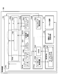
- FIG. 3 is a diagram showing a first example of the detailed configuration of the control device 700.
- the control device 700 includes a CPU 701, a RAM 702A, a ROM 703A, a ROM 703B, and an FPGA 704A.
- the CPU 701 executes various programs recorded (installed) in the ROM 703A, and performs processing according to the contents of the programs.
- the RAM 702A functions as a work area of the CPU 701. Specifically, various programs installed in the ROM 703A are loaded (expanded) into the RAM 702A, and the CPU 701 can execute processes corresponding to the various programs while accessing the RAM 702A.
- Programs such as system software 7031 and application software 7032 are installed in ROM 703A.
- the ROM 703B is configured to be write-protected (WP: Write Protect), that is, write-protected.
- WP Write Protect
- a predetermined program is recorded (installed) and then write-protected is set. ..
- Programs such as the boot loader 7033 and the safe mode system software 7034 are installed in the ROM 703B.
- the CPU 701 first reads and executes the program of the boot loader 7033 of the ROM 703B at the time of startup (for example, at the time of starting up when the power of the injection molding machine 1 is turned on or when restarting based on the reception of a restart signal described later).
- the CPU 701 uses the program of the boot loader 7033 to start the system software 7021 in the set boot mode.
- the boot mode includes a normal boot mode (hereinafter, “normal boot mode”) and a safe mode in which the functions of the system software 7021 are restricted and booted.
- the CPU 701 loads the program of the system software 7031 of the ROM 703A into the RAM 702A by using the program of the boot loader 7033. As a result, the CPU 701 can start the system software 7021 in the normal boot mode.
- the program of the system software 7031 includes a watchdog (WD: WatchDog) transmission function 7031A. As a result, the CPU 701 can periodically output the watchdog signal to the outside at regular intervals (that is, at predetermined time intervals) by using the system software 7021 in the normal startup mode.
- the CPU 701 loads the program of the safe mode system software 7034 of the ROM 703B into the RAM 702A by using the program of the boot loader 7033. As a result, the CPU 701 can start the system software 7021 for the safe mode.
- the functions of the system software 7021 for safe mode are limited to those of the system software 7021 in normal boot mode. As a result, for example, even in a situation where the system software 7021 in the normal boot mode has some abnormality and cannot be booted normally, the safe mode can be used to use the system software 7021 with the minimum functions. It can be started with.
- the system software 7021 for the safe mode includes minimum functions such as a function of communicating with the outside and a function of saving data received from the outside in the internal memory.
- the software for safe mode does not include a function of executing a part or all of the application software 7032 on the CPU 701. That is, the CPU 701 cannot execute a part or all of the program of the application software 7032 by using the program of the system software 7021 for the safe mode.
- the CPU 701 can load the application software 7032 into the RAM 702A under the control of the system software 7021. Then, the CPU 701 can execute the program of the application software 7022 of the RAM 702A.
- the FPGA 704A includes a watchdog monitoring circuit 7041 and a start mode setting register 7042.
- the watchdog monitoring circuit 7041 monitors the presence or absence of the output of the watchdog signal output from the CPU 701 to the outside in response to the WD transmission function 7031A by the system software 7021 in the normal startup mode.
- the watchdog monitoring circuit 7041 sets the start mode of the system software to the start mode setting register 7042. Is transmitted to a command signal (hereinafter, “safe mode setting signal”) for setting "safe mode”. Then, the watchdog monitoring circuit 7041 transmits a command signal (hereinafter, “restart signal”) instructing the CPU 701 to restart.
- a command signal hereinafter, “restart signal”.
- the boot mode setting register 7042 sets the boot mode of the system software 7021 executed by the CPU 701, and the setting content is notified to the CPU 701.
- the "normal startup mode” is set in the startup mode setting register 7042.
- the boot mode setting register 7042 changes the boot mode of the system software from "normal boot mode” to "safe mode” and notifies the CPU 701 of the setting contents. do.
- the CPU 701 can change the startup mode of the next system software accompanying the restart signal from the watchdog monitoring circuit 7041 from the "normal startup mode” to the "safe mode”.
- the boot mode setting register 7042 may be capable of setting (changing) the boot mode of the system software 7021 executed by the CPU 701 according to a predetermined operation input received from the operation device 750.
- the user of the injection molding machine 1 can change the startup mode of the system software 7021 executed by the CPU 701 from "normal mode” to "safe mode", for example, through the operation device 750. Therefore, the user of the injection molding machine 1 can manually start the system software 7021 in the safe mode by manually changing the start mode to the "safe mode” and restarting the CPU 701 through the operating device 750.
- abnormality monitoring process related to the abnormality monitoring by the control device 700 according to this example will be described.
- FIG. 4 is a flowchart schematically showing a first example of abnormality monitoring processing by the control device 700. Specifically, it is a flowchart which shows a specific example of the abnormality monitoring process executed by the FPGA 704A of FIG. This flowchart may be executed at predetermined control cycles, for example, during execution of the system software 7021 corresponding to the normal startup mode by the CPU 701.
- the watchdog monitoring circuit 7041 determines whether or not the latest watchdog signal has been received from the system software 7021 being executed by the CPU 701.
- the latest watchdog signal means, for example, the first watchdog signal in the case of processing the first flowchart after the start of the injection molding machine 1 (control device 700). Further, the latest watchdog signal means, for example, a watchdog signal output after the previous watchdog signal is received in the case of processing the flowchart after that.
- the watchdog monitoring circuit 7041 determines that the system software 7021 running on the CPU 701 is normal, and ends the current process. On the other hand, if the watchdog monitoring circuit 7041 has not received the watchdog signal from the CPU 701, the watchdog monitoring circuit 7041 proceeds to step S104.
- step S104 the watchdog monitoring circuit 7041 determines whether or not a predetermined time has elapsed in a state where the watchdog signal has not been received, with reference to a predetermined timing.
- the predetermined time is a threshold value at which it can be determined that an abnormality has occurred in the system software 7021 being executed by the CPU 701 and the watchdog signal cannot be transmitted.
- the predetermined timing may be the start timing of this flowchart or the reception timing of the previous watchdog signal. If the predetermined time has not elapsed, the watchdog monitoring circuit 7041 returns to step S102 and repeats the processes of steps S102 and S104. On the other hand, when the predetermined time has elapsed, the watchdog monitoring circuit 7041 determines that an abnormality has occurred in the system software 7021 being executed by the CPU 701, and proceeds to step S106.
- step S106 the watchdog monitoring circuit 7041 sets the boot mode of the system software of the CPU 701 to "safe mode" through the boot mode setting register 7042. Specifically, the watchdog monitoring circuit 7041 transmits a safe mode setting signal to the start mode setting register 7042. As a result, the boot mode setting register 7042 can change the boot mode of the system software to "safe mode” in response to the reception of the safe mode setting signal, and notify the CPU 701 of the set contents.
- step S106 the watchdog monitoring circuit 7041 proceeds to step S108.
- step S108 the watchdog monitoring circuit 7041 outputs a restart signal to the CPU 701.
- the CPU 701 forcibly terminates the system software in response to the restart signal, restarts the system software, reads the boot loader 7033, and executes the system software.
- the CPU 701 can load the safe mode system software 7034 into the RAM 702A and start the safe mode system software 7021 according to the setting content of the start mode changed by the notification from the FPGA 704A.
- step S108 the watchdog monitoring circuit 7041 ends the process of the current flowchart.
- the FPGA 704A can determine the presence / absence of an abnormality in the system software 7021 being executed by the CPU 701 based on the presence / absence of the watchdog signal from the CPU 701. Then, when the FPGA 704A determines that an abnormality has occurred in the system software 7021 being executed by the CPU 701, the CPU 701 can start the system software 7021 in the safe mode. Therefore, for example, even if an abnormality occurs in the system software 7021 corresponding to the normal startup mode and the system software 7021 freezes, the system software 7021 can be restarted in the safe mode regardless of the user's operation. ..
- the programs of the system software 7031 and the application software 7032 installed in the ROM 703A may be updated as appropriate.
- the procedure for updating the program installed in the ROM 703A is, for example, the following (A1) to (A3).
- the control device 700 is for updating, which is distributed from a higher-level control device inside the injection molding machine 1, a management device 2 of the injection molding machine 1 (hereinafter, comprehensively or individually "upper-level device"), and the like. Receives program data (for example, difference data of the part to be replaced).
- the control device 700 installs the update program data in the ROM 703A at a predetermined timing.
- the control device 700 restarts the CPU 701 at a predetermined timing after the installation of the update program data is completed.
- the CPU 701 can start the system software 7021 and the application software 7022 by using the system software 7031 and the application software 7032 in which the update program data is reflected.
- control device 700 When the control device 700 installs the update program data in the ROM 703A according to the procedure (A2), the control device 700 transmits a notification (signal) regarding the execution of the update program data installation process to the host device. You can do it. As a result, the host device can grasp that the installed update process of the delivered update program data has been performed.
- Distribution of program data for update may be automatically started, for example, in response to a push notification from the source to the control device 700. Further, the distribution of the program data for update may be started by a manual instruction by the user through the operation device 750. Further, the update program data installation process is performed at a predetermined timing (for example, when the first injection molding machine 1 (control device 700) is stopped (for example, when the power is turned off) after the reception of the update program data is completed). May be started automatically. Further, the process of installing the program data for update may be started by, for example, a manual instruction by the user through the operation device 750.
- the restart of the CPU 701 after the installation of the update program data may be automatically started, or may be started by a manual instruction by the user through the operation device 750.
- the same may apply to the distribution of the update config data, the installation process, and the restart of the FPGA 704A, which will be described later.
- the download of the program data for updating the system software 7031 may fail, and the program data for updating incompletely may be installed. Further, even if the download of the program data for updating the system software 7031 is successful, the installation process may not be completed properly, and the program data for updating incompletely may be installed. In this case, when the system software 7021 is restarted due to the restart of the CPU 701 in the above procedure (A3), the system software 7021 may not be able to start normally on the CPU 701. Similarly, the download of the update program data of the application software 7032 may fail, and the incomplete update program data or the like may be installed.
- the installation process may not be completed properly, and the program data for updating incompletely may be installed.
- the system software 7021 is restarted due to the restart of the CPU 701 in the above procedure (A3), the defective application software 7032 program may affect the restart of the system software 7021. There is sex. As a result, the system software 7021 may not be able to start normally.
- the distributed system software 7031 and application software 7032 update program data itself may contain defects such as serious bugs.
- the system software 7021 may not be able to start normally as in the above case.
- the FPGA 704A (watchdog monitoring circuit 7041) can determine the presence or absence of the watchdog signal transmitted from the system software 7021 executed by the CPU 701 (step S102 in FIG. 4). Therefore, the FPGA 704A can grasp the abnormality that the system software 7021 cannot start normally because the watchdog signal is not received when the CPU 701 is restarted in the above procedure (A3) (NO in step S104 of FIG. 4). .. Then, the FPGA 704A (watchdog monitoring circuit 7041) can automatically start the system software 7021 executed by the CPU 701 in the safe mode in response to the abnormality (steps S106 and S108).
- the CPU 701 when the system software 7021 is restarted in the safe mode by the restart signal from the FPGA 704A (watchdog monitoring circuit 7041), the CPU 701 automatically sends a notification signal indicating that the system software 7021 is restarted in the safe mode to the host device. You may send it.
- the host device can grasp that some abnormality has occurred at the first startup after the update process of the system software 7031 or the application software 7032. Therefore, the host device can perform a process for starting the system software 7021 executed on the CPU 701 in the normal boot mode in response to the reception of the notification signal from the control device 700 (CPU 701).
- the host device may try to reinstall the program data for the update. This is because it is not a defect of the update program data itself.
- the host device may determine that the cause of the update failure is the failure of the download or installation process, for example, when the update is successful in most of the injection molding machines 1 out of the plurality of injection molding machines 1. .. Specifically, the host device may redistribute the update program data to the control device 700 and instruct the reinstallation of the update program data of the system software 7031 and the application software 7032.
- the host device can shift the injection molding machine 1 (control device 700) that has failed to update the system software 7031 or the application software 7032 to a state in which the latest functions can be used at an earlier stage. Therefore, for example, due to the failure to update the system software 7031 of some of the injection molding machines 1 among the plurality of injection molding machines 1, the deployment of the latest functions to all the injection molding machines 1 is delayed. It is possible to suppress a situation in which the production efficiency as a whole is lowered.
- the host device may try to reinstall the program data before the update. For example, when the update fails in most of the injection molding machines 1 among the plurality of injection molding machines 1, the host device determines that the cause of the update failure is a defect in the program data for updating. good. Specifically, the host device may distribute the program data of the old version before the update to the control device 700 and instruct the installation of the program data of the old version of the system software 7031 or the application software 7032.
- control device 700 when the control device 700 is configured to continuously hold the program data of the old version when the program data for update is installed, the higher-level device is the old version held with respect to the control device 700. You may instruct the installation process of program data. Then, the host device may wait for the completion of the update program data in which the defect has been corrected, and then deliver the update program data (corrected version) to the control device 700.
- the host device may try to reinstall the program data before the update, regardless of the cause of the update failure of the system software 7031 or the application software 7032. Then, the host device may redistribute the update program data to the control device 700 after waiting for the update program data to be verified to be free of defects.
- the FPGA 704A can receive the watchdog signal periodically transmitted from the system software 7021 executed on the CPU 701. As a result, the FPGA 704A can grasp, for example, an abnormal state in which some abnormality occurs in the system software 7021 corresponding to the normal startup mode and the watchdog signal cannot be transmitted at a predetermined timing. Further, the FPGA 704A can grasp, for example, a state in which some abnormality occurs in the application software 7022, which affects the operation of the system software 7021, and the watchdog signal cannot be transmitted at a predetermined timing. Therefore, the FPGA 704A can restart the system software 7021 of the CPU 701 in the safe mode in response to the occurrence of the abnormality regardless of the type of the abnormality related to the system software 7021 or the application software 7022.
- the FPGA 704A (an example of the monitoring unit) monitors the abnormality of the CPU 701 (an example of the information processing unit). Then, when an abnormality occurs in the CPU 701, the FPGA 704A restarts the CPU 701 in a safe mode (an example of a predetermined boot mode) whose functions are more limited than those in the normal boot mode.
- the FPGA 704A functions more than the system software 7031 program (an example of the first program) corresponding to the normal startup mode when an abnormality occurs in the system software 7021 or the application software 7022 executed on the CPU 701.
- the system software 7021 is restarted on the CPU 701 using the program of the system software 7034 for safe mode (an example of the second program) limited to the above.
- the injection molding machine 1 can automatically restore the CPU 701 (system software 7021) under the control of the FPGA 704A when an abnormality occurs in the CPU 701 (system software 7021).
- the old program when updating the program of system software 7031, the old program is saved, and if there is a problem with the operation of the new program after the update, the old program is read and restarted to realize automatic recovery. It is also possible to do. However, when this configuration is adopted, it is possible to deal with a situation in which the CPU 701 cannot be started due to a malfunction of the new program after the update. It may not be possible to recover.
- the control device 700 uses the system software 7021 in a safe mode in which the functions are minimized, regardless of any abnormality in the system software 7021 running on the CPU 701. It can be restarted automatically. Therefore, when an abnormality occurs in the CPU 701, the injection molding machine 1 can more appropriately recover the CPU 701 in a form capable of responding to various abnormalities that may occur in the CPU 701.
- the CPU 701 may notify a higher-level device (an example of a higher-level information processing unit) that the CPU 701 has been restarted in the safe mode.
- a higher-level device an example of a higher-level information processing unit
- the CPU 701 can make the host device know that it has automatically recovered from some abnormality and prompt the response to the abnormality.
- the host device may be configured to be able to update program data (an example of data related to processing of the information processing unit) such as system software 7031 and application software 7032.
- the host device can distribute the update program data to the control device 700 and instruct the ROM 703A to install the program data.
- the CPU 701 prompts the host device to return the system software 7031, the application software 7032, etc., which have failed to update, to a normal state in which they can be started in the normal startup mode by performing the above notification. Can be done.
- the host device starts the CPU 701 in the normal startup mode when the CPU 701 notifies that the system software 7021 or the application software 7032 has been restarted in the safe mode after updating the program data. May be processed. For example, if the host device determines that the cause is a download failure or an installation failure, the host device may redistribute the program data for updating the system software 7021 or the application software 7032 and reinstall it. Further, for example, the host device may distribute the program data of the old version before the update and return to the state before the update.
- the host device can automatically restore the system software 7021 of the CPU 701 so that it can be started in the normal boot mode.
- the CPU 701 periodically outputs a watchdog signal (an example of a predetermined signal) to the FPGA 704A under the control of the system software 7021 corresponding to the normal startup mode during operation. Then, the FPGA 704A may determine whether or not there is an abnormality in the CPU 701 depending on whether or not the watchdog signal is received.
- a watchdog signal an example of a predetermined signal
- the FPGA 704A can specifically determine the presence or absence of an abnormality in the CPU 701. Further, the FPGA 704A can determine the presence or absence of an abnormality in the CPU 701 regardless of the type of abnormality. Therefore, the FPGA 704A can automatically restart the CPU 701 in a situation where there is some abnormality.
- the FPGA 704A may monitor an abnormality in the system software 7031 or the application software 7032 executed by the CPU 701 by another method.
- control device 700 ⁇ Detailed configuration of control device> First, the configuration details of the control device 700 according to this example will be described.
- FIG. 5 is a diagram showing a second example of the detailed configuration of the control device 700.
- the parts different from the first example described above will be mainly described.
- the control device 700 includes a CPU 701, a RAM 702A, a ROM 703A, an EEPROM 703C, an FPGA 704A, a reset circuit 705, and a start mode setting circuit 706.
- the boot loader 7033 is installed in the ROM 703A.
- the CPU 701 reads the boot loader 7033 from the ROM 703A and executes it at startup.
- system software 7031 is installed in the ROM 703A as in the case of the first example described above.
- the program of system software 7031 includes a watchdog (WD) monitoring function 7031B.
- the CPU 701 can monitor the presence or absence of the watchdog signal output from the FPGA 704A by using the system software 7021 in the normal startup mode.
- config data 7035 of the FPGA 704A is installed (recorded and saved) in the ROM 703A.
- safe mode configuration data 7036 of the FPGA 704A is installed (recorded and saved) in the EEPROM 703C.
- the FPGA 704A includes a SRAM (Static Random Access Memory) 7043, a watchdog transmission circuit 7044, and a safe mode dedicated circuit 7045.
- SRAM Static Random Access Memory
- the config data 7035 or the safe mode config data 7036 is loaded from the outside according to the start mode.
- the startup mode of the FPGA 704A includes a normal startup mode (normal startup mode) and a safe mode in which the functions of the FPGA 704A are restricted.
- the FPGA 704A is started in the normal start mode, the FPGA 704A is configured under the control of the CPU 701 (system software 7021). Specifically, the FPGA 704A receives the config data 7035 of the ROM 703A and loads it into the SRAM 7043 under the control of the CPU 701.
- the FPGA 704A when the FPGA 704A is started in the safe mode, it configures under its own control. Specifically, the FPGA 704A receives the safe mode config data 7036 of the EEPROM 703C and loads it into the SRAM 7043 under the control of the safe mode dedicated circuit 7045.
- the watchdog transmission circuit 7044 outputs a watchdog signal to the outside periodically (that is, at predetermined time intervals) while the FPGA 704A is in operation.
- the safe mode dedicated circuit 7045 accesses the EEPROM 703C and loads the safe mode config data 7036 into the SRAM 7043. As a result, the safe mode dedicated circuit 7045 can start the FPGA 704A in the safe mode.
- the reset circuit 705 can reset and restart the FPGA 704A under the control of the CPU 701 (system software 7021).
- the boot mode setting circuit 706 sets the boot mode of the FPGA 704A to "normal boot mode” or "safe mode” under the control of CPU 701 (system software 7021).
- the safe mode dedicated circuit 7045 does not perform any configuration-related operation when the FPGA 704A is started when the start mode of the FPGA 704A is set to the "normal start mode” by the start mode setting circuit 706.
- the safe mode dedicated circuit 7045 loads the safe mode config data 7036 into the SRAM 7043 when the FPGA 704A is started.
- the safe mode dedicated circuit 7045 can control the configuration only when the FPGA 704A is started in the safe mode.
- FIG. 6 is a flowchart schematically showing a second example of abnormality monitoring processing by the control device 700. Specifically, it is a flowchart which shows the specific example of the abnormality monitoring process executed by the CPU 701 of FIG. 5 under the control of the system software 7021. This flowchart may be executed at predetermined control cycles, for example, in a state where the FPGA 704A is started and operated in the normal start mode.
- step S202 the CPU 701 determines whether or not the latest watchdog signal has been received from the FPGA 704A (watchdog transmission circuit 7044). When the latest watchdog signal is received from the FPGA 704A, the CPU 701 determines that the FPGA 704A is operating normally, and ends the processing of the current flowchart. On the other hand, the CPU 701 proceeds to step S204 when the latest watchdog signal has not been received from the FPGA 704A.
- step S204 the CPU 701 determines whether or not a predetermined time has elapsed in a state where the watchdog signal has not been received, based on the predetermined timing.
- the predetermined time is a threshold value at which it can be determined that an abnormality has occurred in the operation of the FPGA 704A and the watchdog signal cannot be transmitted.
- the predetermined timing may be the start timing of this flowchart or the reception timing of the previous watchdog signal. If the predetermined time has not elapsed, the CPU 701 returns to step S202 and repeats the processes of steps S202 and S204. On the other hand, when the predetermined time has elapsed, the CPU 701 determines that an abnormality has occurred in the operation of the FPGA 704A, and proceeds to step S206.
- step S206 the CPU 701 outputs a signal for setting the startup mode of the FPGA 704A to the "safe mode” (hereinafter, "safe mode setting signal") to the startup mode setting circuit 706.
- safe mode setting signal a signal for setting the startup mode of the FPGA 704A to the "safe mode”
- the boot mode setting circuit 706 can set the boot mode of the FPGA 704A to "safe mode” in response to the safe mode setting signal from the CPU 701.
- step S206 the CPU 701 proceeds to step S208.
- step S208 the CPU 701 outputs a signal for resetting the FPGA 704A (hereinafter, “reset signal”) to the reset circuit 705.
- reset signal a signal for resetting the FPGA 704A
- the reset circuit 705 can reset and restart the FPGA 704A in response to the reset signal from the CPU 701.
- the start mode of the FPGA 704A is set to the "safe mode” by the start mode setting circuit 706, the safe mode dedicated circuit 7045 operates and the FPGA 704A starts in the safe mode.
- step S208 the CPU 701 completes the processing of the current flowchart.
- the CPU 701 (system software 7021) can determine the presence / absence of an abnormality in the FPGA 704A based on the presence / absence of the watchdog signal from the FPGA 704A. Then, when the CPU 701 determines that an abnormality has occurred in the operation of the FPGA 704A, the CPU 701 can start the FPGA 704A in the safe mode. Therefore, for example, even if an abnormality occurs in the FPGA 704A started in the normal startup mode and the FPGA 704A freezes, the FPGA 704A can be restarted in the safe mode regardless of the user's operation.
- the config data 7035 installed in the ROM 703A may be updated as appropriate.
- the procedure for updating the config data 7035 of the ROM 703A is, for example, the following (B1) to (B3).
- the control device 700 is an update config data (for example, a difference in a portion to be replaced) distributed from a higher-level control device inside the injection molding machine 1 or a management device 2 or the like (upper-level device) of the injection molding machine 1. Data) is received.
- the control device 700 installs the update config data in the ROM 703A at a predetermined timing.
- the control device 700 restarts the FPGA 704A at a predetermined timing after the installation of the update config data is completed.
- the FPGA 704A can be configured and started by the config data 7035 that reflects the config data for update.
- control device 700 When the control device 700 installs the update config data in the ROM 703A according to the procedure (B2), the control device 700 transmits a notification (signal) regarding the execution of the update config data installation process to the host device. You can do it. As a result, the host device can grasp that the installed update process of the delivered update config data has been executed.
- the download of the update config data may fail and the incomplete update config data or the like may be installed.
- the FPGA 704A cannot be started when the FPGA 704A is restarted in the above procedure (B3) due to a defect of the config data 7035 after improper update due to the download failure.
- the installation process may not be completed properly, and incomplete update config data or the like may be installed.
- the FPGA 704A may not be able to start normally when the FPGA 704A is restarted in the above procedure (B3).
- the delivered update config data itself may contain problems such as serious bugs. Also in this case, as in the above case, there is a possibility that the FPGA 704A cannot be started normally.
- the CPU 701 can use the system software 7021 to determine the presence or absence of the watchdog signal transmitted from the FPGA 704A (watchdog transmission circuit 7044) (step S202 in FIG. 6). Therefore, the CPU 701 can grasp the abnormality that the FPGA 704A cannot be started normally because the watchdog signal is not received when the FPGA 704A is restarted in the above procedure (B3) (NO in step S204 of FIG. 6). Then, the CPU 701 can automatically start the FPGA 704A in the safe mode in response to the abnormality (steps S206 and S208).
- the FPGA 704A When the FPGA 704A is reset by the reset circuit 705 and restarted in the safe mode, for example, the FPGA 704A may automatically transmit a notification signal indicating that the restart is performed in the safe mode to the host device. As a result, the host device can grasp that some abnormality has occurred at the first startup after the update process of the config data 7035. Therefore, the host device can perform a process for activating the FPGA 704A in the normal activation mode in response to the reception of the notification signal from the control device 700 (FPGA704A).
- the host device may try to reinstall the update config data. This is because it is not a defect of the update config data itself.
- the host device may determine that the cause of the update failure is the failure of the download or installation process, for example, when the update is successful in most of the injection molding machines 1 out of the plurality of injection molding machines 1. .. Specifically, the host device may redistribute the update config data to the control device 700 and instruct the reinstallation of the update config data of the config data 7035.
- the control device 700 (CPU701) can reinstall the update config data and update the config data 7035 under the control of the system software 7021. Therefore, the host device can shift the injection molding machine 1 (control device 700) that failed to update the config data 7035 to a state in which the latest functions can be used at an earlier stage. Therefore, for example, due to the failure to update the config data 7035 of some of the injection molding machines 1 among the plurality of injection molding machines 1, the deployment of the latest functions to all the injection molding machines 1 is delayed, and the whole It is possible to suppress a situation in which the production efficiency and the like are lowered.
- the host device may try to reinstall the config data before the update. For example, when the update fails in most of the injection molding machines 1 among the plurality of injection molding machines 1, the host device determines that the cause of the update failure is a defect in the update config data. good. Specifically, the host device may distribute the config data of the old version before the update to the control device 700 and instruct the installation of the config data of the old version. Further, when the control device 700 is configured to continuously hold the config data of the old version during the installation process of the config data for update, the higher-level device is the old version held with respect to the control device 700. You may instruct the installation process of the config data. Then, the higher-level device may wait for the completion of the update config data in which the defect has been corrected, and then deliver the update config data (corrected version) to the control device 700.
- the host device may try to reinstall the config data before the update, regardless of the cause of the update failure of the config data 7035. Then, the host device may redistribute the update config data to the control device 700 after waiting for the update config data to be verified to be free of defects.
- the CPU 701 can receive the watchdog signal periodically transmitted from the FPGA 704A (watchdog transmission circuit 7044). As a result, the CPU 701 can grasp, for example, an abnormal state in which some abnormality occurs in the FPGA 704A and the watchdog signal cannot be transmitted at a predetermined timing. Therefore, the CPU 701 can use the system software 7021 to restart the FPGA 704A in the safe mode in response to the occurrence of the abnormality regardless of the type of the abnormality related to the FPGA 704A.
- the CPU 701 (an example of the monitoring unit) monitors the abnormality of the FPGA 704A (an example of the information processing unit). Then, when an abnormality occurs in the CPU 701, the FPGA 704A restarts the CPU 701 in a safe mode (an example of a predetermined boot mode) whose functions are more limited than those in the normal boot mode.
- the CPU 701 monitors the abnormality of the FPGA 704A by using the system software 7021 (an example of predetermined monitoring software), and when the abnormality of the FPGA 704A occurs, the config data 7035 corresponding to the normal startup mode (the first).
- the FPGA 704A is restarted using the safe mode configuration data 7036 (an example of the second configuration data) corresponding to the safe mode different from the configuration data of 1).
- the injection molding machine 1 can automatically restore the FPGA 704A under the control of the CPU 701 (system software 7021) when an abnormality occurs in the FPGA 704A.
- the configuration data 7035 of the FPGA 704A when the configuration data 7035 of the FPGA 704A is updated, the old data is saved, and when there is a failure in the operation of the new data after the update, the old data is read and restarted to realize automatic recovery. It is also possible to adopt it. However, when this configuration is adopted, it is possible to deal with the situation where the FPGA 704A cannot be started due to a malfunction of the new data after the update, and for example, even if another abnormality of the FPGA 704A occurs, the FPGA 704A is automatically operated from the failure. It may not be possible to recover.
- control device 700 can automatically restart the FPGA 704A in a safe mode in which the functions are minimized, regardless of what kind of abnormality occurs in the FPGA 704A. Therefore, when an abnormality occurs in the FPGA 704A, the injection molding machine 1 can more appropriately recover the FPGA 704A in a form capable of responding to various abnormalities that may occur in the FPGA 704A.
- the config data 7035 (first configuration data) is controlled by the system software 7021 (an example of predetermined boot software) executed on the CPU 701. An example) is received from the outside (for example, ROM703A).
- the safe mode config data 7036 (an example of the second configuration data) is provided under the control of the safe mode dedicated circuit 7045 (an example of a predetermined circuit unit) provided inside the FPGA 704A. Receive from the outside (for example, EEPROM 703C).
- the CPU 701 may output a notification (for example, a safe mode setting signal) directed to the FPGA 704A so that the FPGA 704A starts in the safe mode, and may reset the FPGA 704A.
- a notification for example, a safe mode setting signal
- the CPU 701 can configure the FPGA 704A and start it in the normal start mode, while when the FPGA 704A is abnormal, the CPU 701 can be configured under the control of the FPGA 704A and started in the safe mode.
- the FPGA 704A when the FPGA 704A is restarted in the safe mode by the CPU 701, it may notify the host device (an example of the host information processing unit) that the FPGA 704A has been restarted in the safe mode.
- the host device an example of the host information processing unit
- the FPGA 704A can make the host device know that it has automatically recovered from some abnormality and prompt the response to the abnormality.
- the host device may be configured to be able to update the config data 7035 (an example of data related to the processing of the information processing unit).
- the host device can distribute the update config data to the control device 700 and instruct the ROM 703A to install the data.
- the FPGA 704A can urge the host device to return the FPGA 704A to a normal state in which it can be started in the normal start mode by performing the above notification.
- the host device may perform a process for starting the FPGA 704A in the normal startup mode. For example, if the host device determines that the cause is a download failure or installation failure, the update config data may be redistributed and reinstalled. Further, for example, the host device or the like may distribute the program data of the old version before the update and return to the state before the update.
- the host device can automatically restore the FPGA 704A so that it can be started in the normal start mode.
- the FPGA 704A (watchdog transmission circuit 7044) periodically outputs a watchdog signal (an example of a predetermined signal) to the CPU 701 during operation. Then, the CPU 701 may use the system software 7021 to determine whether or not there is an abnormality in the CPU 701 depending on whether or not the watchdog signal is received.
- the CPU 701 can specifically determine the presence or absence of an abnormality in the CPU 701. Further, the CPU 701 can determine the presence or absence of an abnormality in the CPU 701 regardless of the type of abnormality. Therefore, the FPGA 704A can automatically restart the FPGA 704A in a situation where there is some abnormality.
- the CPU 701 may monitor the abnormality of the FPGA 704A by another method.
- control device 700 ⁇ Detailed configuration of control device> First, the configuration details of the control device 700 according to this example will be described.
- FIG. 7 is a diagram showing a third example of the detailed configuration of the control device 700.
- the parts different from the above-mentioned first example and the second example will be mainly described.
- the control device 700 includes a CPU 701, a RAM 702A, a ROM 703A, a ROM 703B, an FPGA 704A, a reset circuit 705, and a start mode setting circuit 706.
- the system software 7031 is installed in the ROM 703A as in the case of the first example and the second example described above.
- the program of the system software 7031 includes the WD monitoring function 7031B as in the case of the second example described above.
- the CPU 701 can monitor the presence or absence of the watchdog signal output from the FPGA 704A by using the system software 7021 in the normal startup mode.
- the config data 7035 is installed in the ROM 703A as in the case of the second example described above.
- the boot loader 7033 is installed in the ROM 703B as in the case of the first example described above.
- the safe mode config data 7036 is installed in the ROM 703B.
- FPGA 704A includes SRAM 7043 and watchdog transmission circuit 7044.
- the SRAM 7043 is loaded with the config data 7035 or the safe mode config data 7036 from the outside according to the start mode when the FPGA 704A is started.
- the FPGA 704A is configured under the control of the CPU 701 (system software 7021) regardless of its boot mode. Specifically, when the FPGA 704A is started in the normal startup mode, it receives the config data 7035 of the ROM 703A and loads it into the SRAM 7043 under the control of the CPU 701 (system software 7021). On the other hand, when the FPGA 704A is started in the safe mode, it receives the safe mode config data 7036 of the ROM 703B and loads it into the SRAM 7043 under the control of the CPU 701 (system software 7021).
- the boot mode setting circuit 706 sets the boot mode of the FPGA 704A to "normal boot mode” or "safe mode” under the control of CPU 701 (system software 7021).
- the CPU 701 can cause the boot mode setting circuit 706 to set the boot mode of the FPGA 704A, and can determine the boot mode of the FPGA 704A by referring to the setting state of the boot mode setting circuit 706.
- FIG. 8 is a flowchart schematically showing a third example of abnormality monitoring processing by the control device 700. Specifically, it is a flowchart which shows a specific example of the abnormality monitoring process executed by the CPU 701 of FIG. This flowchart may be executed at predetermined control cycles, for example, in a state where the FPGA 704A is started and operated in the normal start mode.
- steps S302 and S304 are the same as the processes of steps S202 and S204 of FIG. 6, and therefore the description thereof will be omitted.
- step S304 if the predetermined time has not elapsed, the CPU 701 returns to step S302 and repeats the processes of steps S302 and S304. On the other hand, when the predetermined time has elapsed, the CPU 701 determines that an abnormality has occurred in the operation of the FPGA 704A, and proceeds to step S306.
- step S306 the CPU 701 sets the startup mode of the FPGA 704A to "safe mode".
- the CPU 701 may set the contents in the boot mode setting circuit 706.
- step S306 the CPU 701 proceeds to step S308.
- step S308 the CPU 701 outputs a reset signal to the reset circuit 705.
- the reset circuit 705 can reset the FPGA 704A in response to the reset signal from the CPU 701, and the FPGA 704A can be restarted.
- step S208 the CPU 701 proceeds to step S310.
- step S310 the CPU 701 loads the safe mode config data 7036 of the ROM 703B into the FPGA 704A (SRAM 7043) under the control of the system software 7021 in accordance with the reset (restart) of the FPGA 704A. This allows the CPU 701 to restart the FPGA 704A in safe mode.
- step S310 the CPU 701 ends the processing of the current flowchart.
- the CPU 701 (system software 7021) can determine the presence / absence of an abnormality in the FPGA 704A based on the presence / absence of the watchdog signal from the FPGA 704A. Then, when the CPU 701 determines that an abnormality has occurred in the operation of the FPGA 704A, the CPU 701 can start the FPGA 704A in the safe mode. Therefore, for example, even if an abnormality occurs in the FPGA 704A started in the normal startup mode and the FPGA 704A freezes, the FPGA 704A can be restarted in the safe mode regardless of the user's operation.
- the CPU 701 monitors the abnormality of the FPGA 704A. Then, when an abnormality occurs in the CPU 701, the FPGA 704A restarts the CPU 701 in a safe mode having more limited functions than the normal startup mode. Specifically, the CPU 701 uses the system software 7021 to monitor the abnormality of the FPGA 704A, and when the abnormality of the FPGA 704A occurs, the CPU 701 uses the safe mode config data 7036 different from the config data 7035 corresponding to the normal startup mode. , The FPGA 704A is restarted.
- the injection molding machine 1 can automatically restore the FPGA 704A under the control of the CPU 701 (system software 7021) when an abnormality occurs in the FPGA 704A, as in the case of the second example described above. Further, as in the case of the second example described above, the control device 700 can be automatically restarted in a safe mode in which the functions are minimized, regardless of what kind of abnormality occurs in the FPGA 704A. .. Therefore, when an abnormality occurs in the FPGA 704A, the injection molding machine 1 can more appropriately recover the FPGA 704A in a form capable of responding to various abnormalities that may occur in the FPGA 704A.
- the config data 7035 (first configuration data) is controlled by the system software 7021 (an example of predetermined boot software) executed on the CPU 701. An example) is received from the outside (for example, ROM703A).
- the FPGA 704A when the FPGA 704A is started in the safe mode, it receives the safe mode config data 7036 (an example of the second configuration data) from the outside (for example, ROM 703B) under the control of the system software 7021 executed on the CPU 701.
- the CPU 701 may reset the FPGA 704A and transmit (load) the safe mode config data 7036 from the outside (ROM 703B) to the FPGA 704A (SRAM 7043) by using the system software 7021.
- the CPU 701 can determine the set startup mode of the FPGA 704A under the control of the system software 7021 and configure the FPGA 704A according to the startup mode. Therefore, it is not necessary to provide a dedicated circuit unit inside the FPGA 704A for configuration, a dedicated EEPROM for recording safe mode config data 7036, and the like. Therefore, the configuration of the injection molding machine 1 (control device 700) can be simplified and the cost can be reduced.
- the FPGA 704A monitors the abnormality of the CPU 701
- the CPU 701 monitors the abnormality of the FPGA 704A, but the FPGA 704A and the CPU 701 mutually monitor the other abnormality. May be good.
- FIGS. 4 and 5 may be combined, and the flowcharts (abnormality monitoring process) of FIGS. 4 and 5 may be executed by the FPGA 704A and the CPU 701.
- control device 700 can realize automatic recovery from the abnormality in response to the abnormality of both the CPU 701 (system software 7021, application software 7022, etc.) and the FPGA 704A.
- control device 700 may further have another information processing unit (for example, another CPU, another FPGA, etc.) having a function different from that of the CPU 701 or FPGA 704A. Then, the CPU 701, the FPGA 704A, and the other information processing unit may mutually monitor each other's abnormalities.
- another information processing unit for example, another CPU, another FPGA, etc.
- control device 700 can realize automatic recovery from the abnormality in response to all the abnormalities of the three or more information processing units to be monitored.
- the injection molding machine 1 (control device 700) includes a plurality of information processing units to be monitored for abnormalities, and the plurality of information processing units include the CPU 701 (an example of the first information processing unit). ) And FPGA704A (an example of a second information processing unit). Then, the CPU 701 and the FPGA 704A may monitor each other for an abnormality of the other as a monitoring unit, and if an abnormality occurs in the other, restart the other in the safe mode.
- the CPU 701 and the FPGA 704A may monitor each other for an abnormality of the other as a monitoring unit, and if an abnormality occurs in the other, restart the other in the safe mode.
- control device 700 can automatically recover one of the abnormalities regardless of whether the abnormalities occur in the CPU 701 or the FPGA 704A. Further, it is not necessary to set a dedicated monitoring unit for each of the CPU 701 and the FPGA 704A, which are the abnormal monitoring targets. Therefore, it is possible to simplify the configuration of the injection molding machine 1 (control device 700) and reduce the cost while dealing with the abnormalities of both the CPU 701 and the FPGA 704A.
- the management device 2 (an example of the monitoring device) monitors each abnormality of the plurality of injection molding machines 1 included in the management system SYS.
- the abnormality to be monitored may be an abnormality related to the control device 700, as in the case of abnormality monitoring inside the injection molding machine 1 described above. Further, the abnormality to be monitored may be an abnormality of a device other than the control device 700 (for example, various actuators, sensors, etc.).
- abnormality to be monitored may be the same as in this example in the case of the second example described later.
- the management device 2 may determine whether or not there is an abnormality in each injection molding machine 1 based on, for example, information on the operating status of the injection molding machine 1 transmitted (uploaded) from each injection molding machine 1. Further, the management system SYS may include peripheral devices of the injection molding machine 1 (for example, a device for transporting a completed molded product, a surveillance camera installed around the injection molding machine 1, and the like). In this case, the management device 2 may determine whether or not there is an abnormality in the injection molding machine 1 based on the information regarding the operating status of the injection molding machine 1 transmitted (uploaded) from the peripheral equipment of the injection molding machine 1.
- the control device 700 (CPU701) of the injection molding machine 1 is controlled by the system software 7021 corresponding to the normal start mode, as in the case of the first example of abnormality monitoring inside the injection molding machine 1 described above.
- the watchdog signal may be output sequentially.
- the control device 700 may transmit the watchdog signal sequentially output to the management device 2 through the communication line NW.
- the management device 2 can determine the presence or absence of an abnormality related to the CPU 701 in the same manner as in the case of the first example (FIG. 4) of abnormality monitoring inside the injection molding machine 1 described above.
- the control device 700 of the injection molding machine 1 sequentially outputs a watchdog signal as in the case of the second example and the third example of abnormality monitoring inside the injection molding machine 1 described above. You can. Then, the control device 700 may transmit the watchdog signal sequentially output to the management device 2 through the communication line NW. As a result, the management device 2 checks for the presence or absence of an abnormality related to FPGA 704A by the same method as in the case of the second example (FIG. 6) and the third example (FIG. 8) of the abnormality monitoring inside the injection molding machine 1 described above. You can judge.
- the method for determining the presence or absence of abnormality in the injection molding machine 1 may be the same as in this example in the case of the second example described later.
- the management device 2 transmits a predetermined signal to the target injection molding machine 1 through the communication line NW, and causes the injection molding machine 1 to move from the normal start mode to the injection molding machine 1. It may be restarted in a safe mode with limited functions (an example of a predetermined startup mode).
- the safe mode of the injection molding machine 1 may correspond to, for example, the safe mode of the control device 700 (system software 7021 or FPGA 704A) that controls the injection molding machine 1.
- the function of the injection molding machine 1 is limited according to the operation of the system software 7021 or FPGA 704A corresponding to the safe mode.
- the contents of the safe mode of the injection molding machine 1 may be the same as in this example in the case of the second example described later.
- the predetermined signal transmitted from the management device 2 to the injection molding machine 1 may include a signal for setting the start mode of the system software of the CPU 701 to "safe mode" through the start mode setting register 7042 of FIG. 3 described above. .. Further, the predetermined signal transmitted from the management device 2 to the injection molding machine 1 may further include a restart signal for restarting the CPU 701. As a result, the management device 2 automatically restarts the CPU 701 (system software 7021) in the safe mode in the same manner as in the first example (FIG. 4) of abnormality monitoring inside the injection molding machine 1 described above. Can be done.
- the predetermined signal transmitted from the management device 2 to the injection molding machine 1 is a safe mode setting signal for setting the activation mode of the FPGA 704A to "safe mode" in the activation mode setting circuit 706 of FIG. 5 described above. May include. Further, the predetermined signal transmitted from the management device 2 to the injection molding machine 1 may further include a reset signal for resetting the FPGA 704A in the reset circuit 705 of FIG. 5 described above. As a result, the management device 2 can automatically restart the FPGA 704A in the safe mode in the same manner as in the second example (FIG. 6) of abnormality monitoring inside the injection molding machine 1 described above.
- the predetermined signal transmitted from the management device 2 to the injection molding machine 1 includes a signal for causing the CPU 701 (system software 7021) in FIG. 7 to set the activation mode of the FPGA 704A to "safe mode". good.
- the predetermined signal transmitted from the management device 2 to the injection molding machine 1 may further include a reset signal for resetting the FPGA 704A in the reset circuit 705 of FIG. 7 described above.
- the management device 2 can automatically restart the FPGA 704A in the safe mode in the same manner as in the third example (FIG. 8) of abnormality monitoring inside the injection molding machine 1 described above.
- the method of restarting the injection molding machine 1 from the outside when an abnormality occurs in the injection molding machine 1 may be the same as in the case of the second example described later.
- the management device 2 may be installed in the ROM 703A and distribute the program data for updating the programs of the system software 7031 and the application software 7032 to the injection molding machine 1 through the communication line NW. As a result, the management device 2 can update various programs installed in the injection molding machine 1 (ROM703A) through the control device 700.
- control device 700 when the control device 700 performs a process of installing the distributed update program data in the ROM 703A, the control device 700 sends a notification (signal) regarding the execution of the update program data installation process through the communication line NW. May be sent to. As a result, the management device 2 can grasp that the installed update process of the delivered update program data has been executed.
- the management device 2 is, for example, a program when an abnormality occurs in the CPU 701 (system software 7021) and the injection molding machine 1 is restarted within a predetermined period after the update program data installation process is executed. You may judge that the update of is unsuccessful.
- the predetermined period is, for example, the maximum time that can be assumed from the completion of the installation process of the program data for updating in the above procedure (A2) to the completion of the restart of the CPU 701 (system software 7021) in the procedure (A3). It may be predetermined by adding a certain amount of margin to the value. Then, in this case, the management device 2 may perform a process for starting the CPU 701 (system software 7021) in the normal startup mode.
- the above predetermined period may be the same as in this example in the case of the second example described later.
- the management device 2 may try to reinstall the program data for the update. Specifically, the management device 2 may redistribute the update program data to the control device 700 and instruct the reinstallation of the update program data of the system software 7031 and the application software 7032. As a result, the management device 2 can shift the injection molding machine 1 (control device 700) that has failed to update the system software 7031 and the application software 7032 to a state in which the latest functions can be used at an earlier stage.
- the management device 2 may try to reinstall the program data before the update.
- the management device 2 may try to reinstall the program data before the update.
- different versions of the injection molding machine 1 control device 700
- the management device 2 may distribute the program data of the old version before the update to the control device 700, and instruct the installation of the program data of the old version of the system software 7031 or the application software 7032.
- control device 700 when the control device 700 is configured to continuously hold the program data of the old version during the installation process of the program data for update, the management device 2 has the old version held with respect to the control device 700. You may instruct the installation process of the program data of. Then, the management device 2 may wait for the completion of the update program data in which the defect has been corrected, and then deliver the update program data (corrected version) to the control device 700.
- the management device 2 may try to reinstall the program data before the update, regardless of the cause of the program update failure. Then, the management device 2 may redistribute the update program data to the control device 700 after waiting for the update program data to be verified to be free of defects.
- the content of the process for starting the CPU 701 (system software 7021) in the normal function mode may be the same as in this example in the case of the second example described later.
- the management device 2 may distribute the update data (update config data) of the config data 7035 installed in the ROM 703A to the injection molding machine 1 through the communication line NW.
- the management device 2 can update the config data 7035 of the FPGA 704A installed in the injection molding machine 1 (ROM703A) through the control device 700.
- control device 700 when the control device 700 performs a process of installing the distributed update config data in the ROM 703A, the control device 700 sends a notification (signal) regarding the execution of the update config data installation process through the communication line NW. May be sent to. As a result, the management device 2 can grasp that the installed update process of the delivered update config data has been executed.
- the management device 2 updates the config data 7035. You may judge that it has failed.
- the predetermined period has a certain margin in the maximum value assumed as the time required from the completion of the installation process of the config data for updating in the above procedure (B2) to the completion of the restart of the FPGA 704A in the procedure (B3). It may be predetermined in the form of adding minutes. Then, in this case, the management device 2 may perform a process for starting the FPGA 704A in the normal start mode.
- the above predetermined period may be the same as in this example in the case of the second example described later.
- the management device 2 may try to reinstall the update config data. This is because it is not a defect of the update config data itself. Specifically, the management device 2 may redistribute the update config data to the control device 700 and instruct the reinstallation of the update config data of the config data 7035. As a result, the control device 700 (CPU701) can reinstall the update config data and update the config data 7035 under the control of the system software 7021.
- the management device 2 can shift the injection molding machine 1 (control device 700) that failed to update the config data 7035 to a state in which the latest functions can be used at an earlier stage. Therefore, for example, due to the failure to update the config data 7035 of some of the injection molding machines 1 among the plurality of injection molding machines 1, the deployment of the latest functions to all the injection molding machines 1 is delayed, and the whole It is possible to suppress a situation in which the production efficiency and the like are lowered.
- the management device 2 may try to reinstall the config data before the update. ..
- the management device 2 may try to reinstall the config data before the update. ..
- different versions of the injection molding machine 1 control device 700
- the management device 2 may distribute the config data of the old version before the update to the control device 700 and instruct the installation of the config data of the old version.
- the management device 2 when the control device 700 is configured to continuously hold the config data of the old version during the installation process of the config data for update, the management device 2 has the old version held with respect to the control device 700. You may instruct the installation process of the config data of. Then, the management device 2 may wait for the completion of the update config data in which the defect has been corrected, and then deliver the update config data (corrected version) to the control device 700.
- the management device 2 may try to reinstall the config data before the update, regardless of the cause of the update failure of the config data 7035. Then, the management device 2 may redistribute the update config data to the control device 700 after waiting for the update config data to be verified to be free of defects.
- the content of the process for starting the FPGA 704A in the normal function mode may be the same as in this example in the case of the second example described later.
- the management device 2 is provided outside the injection molding machine 1 and monitors the abnormality of the injection molding machine 1. Then, when an abnormality occurs in the injection molding machine 1, the management device 2 automatically restarts the injection molding machine 1 in a safe mode having more limited functions than the normal start mode.
- the management device 2 can monitor the abnormality of the injection molding machine 1 from the outside of the injection molding machine 1 and automatically restore the injection molding machine 1 when the abnormality occurs in the injection molding machine 1. Further, the management device 2 can automatically restart the injection molding machine 1 in a safe mode in which the functions are minimized, no matter what kind of abnormality occurs in the injection molding machine 1. Therefore, when an abnormality occurs in the injection molding machine 1, the management device 2 automatically restores the injection molding machine 1 more appropriately in a form capable of responding to various abnormalities that may occur in the injection molding machine 1. Can be done.
- the management device 2 may be configured so that the data inside the injection molding machine 1 can be updated.
- the management device 2 can, for example, update the data after restarting in the safe mode when an abnormality occurs, and eliminate the cause of the abnormal state in the normal startup mode.
- the management device 2 when an abnormality occurs in the injection molding machine 1 after updating the data and the injection molding machine 1 is automatically restarted in the safe mode, the management device 2 performs injection molding in the normal start mode.
- the process for starting the machine 1 may be performed.
- the management device 2 can be automatically restored so that the injection molding machine 1 can be started in the normal start mode.
- the management device 2 may monitor each abnormality of the plurality of injection molding machines 1.
- the plurality of injection molding machines 1 include two or more injection molding machines 1 having different versions from each other.
- the management device 2 can continue to monitor the entire plurality of injection molding machines 1 even in a situation where different versions of the injection molding machines 1 are mixed in the plurality of injection molding machines 1. .. Therefore, the management device 2 can continue the operation such as monitoring even in a situation where some injection molding machines 1 are not successfully updated and different versions of the injection molding machines 1 are unintentionally mixed. ..
- the master machine (a monitoring device, an example of another injection molding machine) among the plurality of injection molding machines 1 included in the management system SYS performs abnormality monitoring of each slave machine under the control of its own machine. It's okay. Then, when an abnormality occurs in the slave unit, the master unit transmits a predetermined signal to the target slave unit through the communication line NW, and the slave unit is placed in a safe mode in which the functions of the slave unit are restricted compared to the normal startup mode. It may be restarted automatically.
- the master machine can monitor the abnormality of the slave machine from the outside and automatically recover the slave machine when an abnormality occurs in the slave machine.
- the master machines may mutually perform abnormality monitoring. Then, when an abnormality occurs in the other master machine, one master machine transmits a predetermined signal to the other master machine through the communication line NW, and the other master machine functions as the master machine rather than the normal start mode. May be restarted automatically in a restricted safe mode.
- one master machine can monitor the abnormality of the other master machine, and when an abnormality occurs in the other master machine, the other master machine can be automatically restored. Therefore, it is possible to simplify the configuration of the management system SYS and reduce the cost while dealing with both abnormalities.
- a specific slave machine may monitor an abnormality of the corresponding master machine. Then, when an abnormality occurs in the master machine, the specific slave machine transmits a predetermined signal to the target master machine through the communication line NW, and the function of the master machine is restricted compared to the normal start mode. It may be restarted automatically in safe mode.
- the slave machine can monitor the abnormality of the master machine from the outside and automatically recover the master machine when an abnormality occurs in the master machine.
- abnormality monitoring can be performed between the master unit and the slave unit. Therefore, it is possible to simplify the configuration of the management system SYS and reduce the cost while dealing with both abnormalities.
- the master machine may, for example, distribute program data for updating such as a program of system software 7031 or application software 7032 installed in ROM 703A to a slave machine through a communication line NW.
- program data for updating such as a program of system software 7031 or application software 7032 installed in ROM 703A
- NW a communication line
- the master machine can update various programs installed in the slave machine (ROM703A) through the control device 700.
- control device 700 when the control device 700 performs a process of installing the distributed update program data in the ROM 703A, the control device 700 sends a notification (signal) regarding the execution of the update program data installation process to the master machine through the communication line NW. You may send it. As a result, the master machine can grasp that the installation process of the delivered update program data has been performed on the slave machine.
- the master machine for example, when an abnormality occurs in the CPU 701 (system software 7021) within a predetermined period after the installation process of the update program data in the slave machine is performed and the slave machine is restarted. It may be determined that the program update has failed. Then, in this case, the master machine may perform a process for starting the CPU 701 (system software 7021) of the slave machine in the normal start mode.
- the master machine can be automatically restored so that the CPU 701 (system software 7021) of the slave machine can be started in the normal start mode.
- the master machine may distribute the update data (update config data) of the config data 7035 installed in the ROM 703A to the slave machine through the communication line NW, for example, as described above.
- the master machine can update the config data 7035 of the FPGA 704A installed in the slave machine (ROM703A) through the control device 700.
- control device 700 when the control device 700 performs a process of installing the distributed update config data in the ROM 703A, the control device 700 sends a notification (signal) regarding the execution of the update config data installation process to the master machine through the communication line NW. You may send it. As a result, the master machine can grasp that the installation process of the delivered update config data has been executed on the slave machine.
- the master machine will update the config data 7035. You may judge that it has failed. Then, in this case, the management device 2 may perform a process for starting the FPGA 704A in the normal start mode.
- the master machine performs the same function as the management device 2 of the above-mentioned first example with the slave machine as the monitoring target, and has the same operation and effect as the case of the above-mentioned first example. ..
- the method of monitoring an abnormality, the method of automatically recovering from an abnormality, and the like have been described for the injection molding machine 1, but any machine (for example, another industrial machine) or device (for example, for example) has been described.
- a similar method may be applied to home appliances, etc.).
- Other industrial machines include stationary machines installed in factories, such as machine tools and production robots.
- other industrial machines include, for example, mobile work machines.
- Mobile work machines include, for example, construction machines such as excavators and bulldozers, agricultural machines such as combines, and transport machines such as mobile cranes.
- Injection molding machine (monitoring device) 2 Management device (monitoring device) 100 Mold clamping device 200 Ejector device 300 Injection device 400 Mobile device 700 Control device 701 CPU (information processing unit, monitoring unit) 702 memory device 702A RAM 703 Auxiliary storage device 703A, 703B ROM 703C EEPROM 704 Interface device 704A FPGA (monitoring unit, information processing unit) 705 Reset circuit 706 Start mode setting circuit 750 Operation device 760 Display device 7031 System software (first program data) 7034 Safe mode system software (second program data) 7035 configuration data (first configuration data) 7036 Safe mode configuration data (second configuration data) SYS injection molding machine management system (injection molding machine system)
Landscapes
- Engineering & Computer Science (AREA)
- Software Systems (AREA)
- Manufacturing & Machinery (AREA)
- Mechanical Engineering (AREA)
- Theoretical Computer Science (AREA)
- Computer Security & Cryptography (AREA)
- Physics & Mathematics (AREA)
- General Engineering & Computer Science (AREA)
- General Physics & Mathematics (AREA)
- Injection Moulding Of Plastics Or The Like (AREA)
Priority Applications (4)
| Application Number | Priority Date | Filing Date | Title |
|---|---|---|---|
| CN202180009165.3A CN114981063A (zh) | 2020-03-03 | 2021-02-17 | 注射成型机、注射成型机系统及监视装置 |
| DE112021001374.2T DE112021001374T5 (de) | 2020-03-03 | 2021-02-17 | Spritzgiessmaschine, spritzgiessmaschinensystem, und überwachungsvorrichtung |
| JP2022505106A JP7728746B2 (ja) | 2020-03-03 | 2021-02-17 | 射出成形機 |
| US17/873,868 US20220355522A1 (en) | 2020-03-03 | 2022-07-26 | Injection molding machine, injection molding machine system, and monitoring device |
Applications Claiming Priority (2)
| Application Number | Priority Date | Filing Date | Title |
|---|---|---|---|
| JP2020036151 | 2020-03-03 | ||
| JP2020-036151 | 2020-03-03 |
Related Child Applications (1)
| Application Number | Title | Priority Date | Filing Date |
|---|---|---|---|
| US17/873,868 Continuation US20220355522A1 (en) | 2020-03-03 | 2022-07-26 | Injection molding machine, injection molding machine system, and monitoring device |
Publications (1)
| Publication Number | Publication Date |
|---|---|
| WO2021177032A1 true WO2021177032A1 (ja) | 2021-09-10 |
Family
ID=77612660
Family Applications (1)
| Application Number | Title | Priority Date | Filing Date |
|---|---|---|---|
| PCT/JP2021/005904 Ceased WO2021177032A1 (ja) | 2020-03-03 | 2021-02-17 | 射出成形機、射出成形機システム、監視装置 |
Country Status (5)
| Country | Link |
|---|---|
| US (1) | US20220355522A1 (https=) |
| JP (1) | JP7728746B2 (https=) |
| CN (1) | CN114981063A (https=) |
| DE (1) | DE112021001374T5 (https=) |
| WO (1) | WO2021177032A1 (https=) |
Cited By (1)
| Publication number | Priority date | Publication date | Assignee | Title |
|---|---|---|---|---|
| WO2026062871A1 (ja) * | 2024-09-20 | 2026-03-26 | 株式会社日立製作所 | 制御システム及び制御方法 |
Citations (1)
| Publication number | Priority date | Publication date | Assignee | Title |
|---|---|---|---|---|
| JP2009196372A (ja) * | 1998-10-05 | 2009-09-03 | Husky Injection Molding Syst Ltd | 射出成形システム用統合制御プラットフォーム |
Family Cites Families (19)
| Publication number | Priority date | Publication date | Assignee | Title |
|---|---|---|---|---|
| JPS5755432A (en) * | 1980-09-20 | 1982-04-02 | Sumitomo Electric Ind Ltd | Watchdog timer circuit |
| JPS60230817A (ja) * | 1984-04-28 | 1985-11-16 | Etou Denki Kk | 射出成形機制御装置 |
| JPS63311899A (ja) * | 1987-06-15 | 1988-12-20 | Hitachi Ltd | 遠隔診断装置 |
| JPH05189272A (ja) * | 1992-01-16 | 1993-07-30 | Honda Motor Co Ltd | コントローラ |
| JPH11268096A (ja) * | 1998-12-28 | 1999-10-05 | Toyo Mach & Metal Co Ltd | 成形機および成形機のトラブル診断方式 |
| JP2004054616A (ja) * | 2002-07-19 | 2004-02-19 | Hitachi Ltd | ファームウェア自動修復機能を有する情報処理装置 |
| KR100891094B1 (ko) * | 2007-05-22 | 2009-03-31 | 삼성전자주식회사 | 최종 화면 복구 장치 및 방법 |
| US9740178B2 (en) * | 2013-03-14 | 2017-08-22 | GM Global Technology Operations LLC | Primary controller designation in fault tolerant systems |
| US10142381B2 (en) * | 2014-07-22 | 2018-11-27 | Intellivision Technologies Corp. | System and method for scalable cloud services |
| JP5715208B2 (ja) * | 2013-08-27 | 2015-05-07 | ファナック株式会社 | 射出成形機の制御装置 |
| JP5890503B1 (ja) * | 2014-10-08 | 2016-03-22 | ファナック株式会社 | 複数の射出装置を備えた射出成形機 |
| US10142167B2 (en) * | 2015-05-13 | 2018-11-27 | Cisco Technology, Inc. | Peer-assisted image update with self-healing capabilities |
| JP6526545B2 (ja) * | 2015-11-11 | 2019-06-05 | 住友重機械工業株式会社 | 射出成形用情報管理装置、射出成形機、および射出成形用情報管理方法 |
| US9772894B2 (en) * | 2016-01-29 | 2017-09-26 | Netapp, Inc. | Systems, methods, and machine-readable media to perform state data collection |
| JP6729407B2 (ja) | 2017-01-13 | 2020-07-22 | 株式会社デンソー | マイクロコンピュータ |
| JP6776141B2 (ja) * | 2017-01-31 | 2020-10-28 | 住友重機械工業株式会社 | 成形条件管理装置、および射出成形機 |
| JP7214659B2 (ja) * | 2018-01-16 | 2023-01-30 | 住友重機械工業株式会社 | 射出成形機 |
| US10831605B2 (en) * | 2018-04-27 | 2020-11-10 | Rovi Guides, Inc. | System and method for detection of, prevention of, and recovery from software execution failure |
| JP2020036151A (ja) | 2018-08-29 | 2020-03-05 | セイコーエプソン株式会社 | スピーカー用振動板、スピーカー用振動板製造装置、及び、スピーカー用振動板の製造方法 |
-
2021
- 2021-02-17 WO PCT/JP2021/005904 patent/WO2021177032A1/ja not_active Ceased
- 2021-02-17 JP JP2022505106A patent/JP7728746B2/ja active Active
- 2021-02-17 CN CN202180009165.3A patent/CN114981063A/zh active Pending
- 2021-02-17 DE DE112021001374.2T patent/DE112021001374T5/de active Pending
-
2022
- 2022-07-26 US US17/873,868 patent/US20220355522A1/en active Pending
Patent Citations (1)
| Publication number | Priority date | Publication date | Assignee | Title |
|---|---|---|---|---|
| JP2009196372A (ja) * | 1998-10-05 | 2009-09-03 | Husky Injection Molding Syst Ltd | 射出成形システム用統合制御プラットフォーム |
Cited By (1)
| Publication number | Priority date | Publication date | Assignee | Title |
|---|---|---|---|---|
| WO2026062871A1 (ja) * | 2024-09-20 | 2026-03-26 | 株式会社日立製作所 | 制御システム及び制御方法 |
Also Published As
| Publication number | Publication date |
|---|---|
| US20220355522A1 (en) | 2022-11-10 |
| DE112021001374T5 (de) | 2022-12-15 |
| JP7728746B2 (ja) | 2025-08-25 |
| JPWO2021177032A1 (https=) | 2021-09-10 |
| CN114981063A (zh) | 2022-08-30 |
Similar Documents
| Publication | Publication Date | Title |
|---|---|---|
| JP7472042B2 (ja) | 射出成形機、射出成形システム | |
| JP7337843B2 (ja) | 射出成形機、射出成形システム | |
| TWI791686B (zh) | 射出成形機 | |
| US20220355522A1 (en) | Injection molding machine, injection molding machine system, and monitoring device | |
| JP6812286B2 (ja) | 射出成形機 | |
| EP3895873B1 (en) | Injection molding machine and controller | |
| EP3957460B1 (en) | Injection molding machine system and controller for industrial machinery | |
| JP7547713B2 (ja) | 射出成形機システム、射出成形機 | |
| JP7479904B2 (ja) | 射出成形機システム、射出成形機、情報処理装置 | |
| US20220274305A1 (en) | Injection molding machine and controller | |
| WO2021201006A1 (ja) | 射出成形機、射出成形機システム、管理装置 | |
| JP7632976B2 (ja) | 射出成形機、産業機械のコントローラ | |
| JP2021160223A (ja) | 産業機械用制御装置、射出成形機 | |
| CN116001227A (zh) | 工业机械的控制装置及工业机械的控制方法 | |
| JP2021146592A (ja) | 射出成形機、産業機械 | |
| CN116669883A (zh) | 注射成型机及控制器 |
Legal Events
| Date | Code | Title | Description |
|---|---|---|---|
| 121 | Ep: the epo has been informed by wipo that ep was designated in this application |
Ref document number: 21764662 Country of ref document: EP Kind code of ref document: A1 |
|
| ENP | Entry into the national phase |
Ref document number: 2022505106 Country of ref document: JP Kind code of ref document: A |
|
| 122 | Ep: pct application non-entry in european phase |
Ref document number: 21764662 Country of ref document: EP Kind code of ref document: A1 |