WO2021176715A1 - エレベーター装置 - Google Patents
エレベーター装置 Download PDFInfo
- Publication number
- WO2021176715A1 WO2021176715A1 PCT/JP2020/009814 JP2020009814W WO2021176715A1 WO 2021176715 A1 WO2021176715 A1 WO 2021176715A1 JP 2020009814 W JP2020009814 W JP 2020009814W WO 2021176715 A1 WO2021176715 A1 WO 2021176715A1
- Authority
- WO
- WIPO (PCT)
- Prior art keywords
- elevator
- monitoring data
- storage unit
- unit
- failure
- Prior art date
- Legal status (The legal status is an assumption and is not a legal conclusion. Google has not performed a legal analysis and makes no representation as to the accuracy of the status listed.)
- Ceased
Links
Images


Classifications
-
- B—PERFORMING OPERATIONS; TRANSPORTING
- B66—HOISTING; LIFTING; HAULING
- B66B—ELEVATORS; ESCALATORS OR MOVING WALKWAYS
- B66B3/00—Applications of devices for indicating or signalling operating conditions of elevators
-
- B—PERFORMING OPERATIONS; TRANSPORTING
- B66—HOISTING; LIFTING; HAULING
- B66B—ELEVATORS; ESCALATORS OR MOVING WALKWAYS
- B66B5/00—Applications of checking, fault-correcting, or safety devices in elevators
Definitions
- This disclosure relates to an elevator device.
- Patent Document 1 discloses a technique for efficiently restoring the state immediately before a failure when the control board of the elevator control device is regenerated.
- the elevator monitoring device of this technology has a field adjustment data storage unit and a comparison source data storage unit.
- the on-site adjustment data storage unit constantly reads and stores the on-site adjustment data stored in the elevator control board. Then, the on-site adjustment data of the on-site adjustment data storage unit is compared with the comparison source data of the comparison source data storage unit, and if there is a difference, the on-site adjustment data is stored in the comparison source data storage unit.
- the on-site adjustment data stored in the comparison source data storage unit is stored in the center data storage unit of the monitoring center. When replacing the control board, the on-site adjustment data stored in the center data storage unit is written to the new board.
- the on-site adjustment data stored in the monitoring center is always the latest adjustment data.
- Such a device configuration that performs constant calculation is inefficient because it causes an increase in calculation load and communication load.
- the present disclosure has been made to solve the above-mentioned problems, and in an elevator device that stores elevator monitoring data, it is possible to efficiently prevent loss of monitoring data by utilizing the result of elevator failure detection.
- the purpose is to provide an elevator device capable of.
- an operation control unit that controls the operation of the elevator
- a storage unit that stores monitoring data of the elevator sequentially acquired by the operation control unit
- an interface unit connected to an external device through a communication path
- an interface unit connected to an external device through a communication path
- an interface unit connected to an external device through a communication path
- an interface unit connected to an external device through a communication path
- an interface unit connected to an external device through a communication path
- an interface unit connected to an external device through a communication path
- the elevator device of the present disclosure saves the monitoring data stored in the storage unit to an external device when it is detected that there is a failure requiring replacement of the storage unit. As described above, according to the elevator device of the present disclosure, since it is determined whether to save the monitoring data by utilizing the result of the failure detection of the elevator, it is possible to efficiently prevent the loss of the monitoring data.
- FIG. It is a figure which shows the example of the elevator apparatus of Embodiment 1.
- FIG. It is a figure which shows the example of the control device and communication device of Embodiment 1.
- It is a flowchart which shows the control routine of the failure detection processing which is executed in the control apparatus in Embodiment 1.
- FIG. It is a flowchart which shows the control routine of the monitoring data save process and save data write-back process executed in the control apparatus in Embodiment 1.
- FIG. It is a figure which shows the example of the hardware resource of a control device.
- It is a figure which shows another example of the hardware resource of a control device.
- It is a flowchart which shows the control routine of the monitoring data save process and save data write-back process executed in the control apparatus in Embodiment 2.
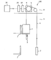
- FIG. 1 is a diagram showing an example of the elevator device of the first embodiment.
- the elevator device 100 includes, for example, a basket 1 and a balance weight 2.
- the car 1 moves up and down in the hoistway 3.
- the balance weight 2 moves up and down on the hoistway 3.
- the car 1 and the counterweight 2 are suspended from the hoistway 3 by the main rope 4.
- the main rope 4 is wound around the drive sheave 6 of the hoisting machine 5.
- the control device 10 controls various devices such as the hoisting machine 5.
- the control device 10 controls the rotation and stop of the drive sheave 6.
- the car 1 moves according to the rotation of the drive sheave 6.
- FIG. 1 shows an example in which the hoisting machine 5 and the control device 10 are installed in the machine room 8 above the hoistway 3.
- the hoisting machine 5 and the control device 10 may be installed in the hoistway 3.
- the hoisting machine 5 may be installed at the top of the hoistway 3 or in the pit of the hoistway 3.
- the communication device 20 is connected to the control device 10 via a communication path.
- the communication device 20 is a device for communicating with the remote maintenance server 30.
- the communication device 20 is provided at the same location as the elevator device 100.
- the remote maintenance server 30 is connected to the communication device 20 via a communication path.
- the remote maintenance server 30 is, for example, an external device provided in a maintenance company in a remote location different from the location of the elevator device 100.
- the communication path connecting the communication device 20 and the remote maintenance server 30 is not limited.
- FIG. 2 is a diagram showing an example of the control device and the communication device of the first embodiment.
- the control device 10 includes an operation control unit 12, a determination unit 14, a storage unit 16, and an interface unit 18.
- the operation control unit 12 controls various devices such as the hoisting machine 5.
- the operation control unit 12 controls various devices to perform normal operation of the elevator device 100.
- the normal operation is an operation in which the car 1 is sequentially answered to the registered calls.
- the storage unit 16 stores the monitoring data of the elevator device 100 sequentially acquired by the operation control unit 12.
- the monitoring data here is, for example, operation data or nominal data of the elevator device 100.
- the operation data includes, for example, a running state, a door open / closed state, a car load, or a car position.
- Call data includes, for example, elevator call registration, call assignment, or call response data.
- the determination unit 14 includes a failure detection unit 141 and a data control unit 142 as its functional block.
- the failure detection unit 141 detects an elevator failure based on the detection values of sensors provided in various parts of the elevator.
- the data control unit 142 controls processing related to transmission / reception of monitoring data stored in the storage unit 16.
- the interface unit 18 is an interface for connecting a communication path leading to the remote maintenance server 30 as an external device.
- the remote maintenance server 30 is connected to the interface unit 18 via the communication device 20.
- the communication device 20 controls data communication between the control device 10 and the remote maintenance server 30 of the maintenance company.
- the communication device 20 includes an interface unit 22, a control unit 24, and a communication unit 26.
- the interface unit 22 transmits and receives monitoring data to and from the interface unit 18 of the control device 10.
- the control unit 24 controls reading and writing of monitoring data from the control device 10 and writing and writing of monitoring data to the remote maintenance server 30.
- the communication unit 26 communicates with the remote maintenance server 30 through the communication path.
- the communication path here is, for example, a telephone line.
- the maintenance company regularly inspects the condition of the elevator device 100.
- the control unit 24 periodically receives the monitoring data stored in the storage unit 16 of the control device 10 and transmits it to the remote maintenance server 30.
- the maintenance company monitors the state of the elevator device 100 based on the monitoring data transmitted from the communication device 20 to the remote maintenance server 30.
- the elevator device 100 of the present embodiment performs failure detection processing, monitoring data evacuation processing, and monitoring data restoration processing as its characteristic operations.
- the failure detection process is a process for detecting a failure of the elevator device 100.
- the failure detection process is a process that is repeatedly executed by the determination unit 14 of the control device 10 when the elevator device 100 is in normal operation.
- FIG. 3 is a flowchart showing a control routine of the failure detection process executed in the control device according to the first embodiment.
- step S100 of the control routine shown in FIG. 3 first, it is determined whether or not the failure detection unit 141 has detected a failure of the elevator device 100. As a result, if the failure detection unit 141 does not detect the occurrence of any failure in the elevator, the process proceeds to step S102, and if the failure detection unit 141 detects the occurrence of a failure, the process proceeds to step S104.
- step S102 the operation control unit 12 continues the normal operation of the elevator device 100.
- step S104 the operation control unit 12 executes an operation stop process for stopping the normal operation.
- the process proceeds to the process of step S106.
- step S106 the determination unit 14 outputs a failure code according to the detected failure.
- the failure code is a code indicating a failure that has occurred. For example, when a failure occurs in the power supply circuit provided in the control device 10, the failure detection unit 141 outputs a failure code indicating that the failure has occurred in the power supply circuit.
- the failure code is transmitted to the communication device 20 via the interface unit 18.
- the communication device 20 transmits the failure code to the remote maintenance server 30 of the maintenance company.
- a maintenance company receives a failure code from the elevator device 100, the maintenance company identifies the cause of the failure based on the received failure code and performs maintenance work. When the maintenance work is completed, the normal operation of the elevator device 100 is resumed. Here, maintenance work may require board replacement. When the storage unit 16 is mounted on the board to be replaced, the data stored in the storage unit 16 is also removed by the board replacement. If the monitoring data stored in the storage unit 16 is lost, the subsequent maintenance management may be affected.
- the monitoring data stored in the storage unit 16 is stored.
- the monitoring data save process for temporarily saving the data to the remote maintenance server 30 of the maintenance company is executed. Further, in the elevator device 100, after the maintenance work is completed, the saved data write-back process of writing back the saved monitoring data to the storage unit 16 is executed. According to such a process, it is possible to prevent the accumulated monitoring data from being lost in the event of a failure requiring board replacement.
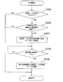
- FIG. 4 is a flowchart showing a control routine of the monitoring data save process and the save data write-back process executed in the control device according to the first embodiment.
- step S120 of the control routine shown in FIG. 4 it is determined whether or not a failure code is output in the failure detection process. As a result, if the failure code is not output, this control routine is terminated, and if the failure code is output, the process proceeds to the next step S122.
- step S122 it is determined whether or not the detected failure is a failure for which the board including the storage unit 16 is to be replaced, based on the output failure code. As a result, if the substrate including the storage unit 16 is not a replacement target, this control routine is terminated. On the other hand, in the process of step S122, when the substrate including the storage unit 16 is to be replaced, the process proceeds to the next step S124.
- step S124 an application for temporarily storing the monitoring data stored in the storage unit 16 on the remote maintenance server 30 of the maintenance company is notified.
- the control device 10 notifies the remote maintenance server 30 of the maintenance company of the application via the communication device 20.
- the monitoring data stored in the storage unit 16 is transmitted to the remote maintenance server 30 via the communication device 20.
- the transmitted monitoring data is temporarily stored in the storage device of the remote maintenance server 30.
- step S1208 it is determined whether or not the elevator device 100 has started normal operation.
- the operation of the stopped elevator device 100 is restarted.
- step S130 the maintenance company is notified of the application for writing back the monitoring data saved in the remote maintenance server 30.
- the control device 10 notifies the remote maintenance server 30 of the maintenance company of the application via the communication device 20.
- the control device 10 receives the monitoring data stored in the remote maintenance server 30 via the communication device 20. The received monitoring data is written back to the storage unit 16 of the control device 10.
- the elevator device 100 configured as described above, it is possible to prevent the loss of the monitoring data stored in the storage unit even when the substrate including the storage unit 16 is replaced.
- the elevator device 100 of Embodiment 1 may apply the modified mode as follows.
- Control device 10 In the present embodiment, the operation control unit 12, the failure detection unit 141, the determination unit 14 including the data control unit 142, the storage unit 16, and the interface unit 18 show the functions of the control device 10.
- FIG. 5 is a diagram showing an example of hardware resources of the control device.
- the control device 10 includes a processing circuit 101 including, for example, a processor 102 and a memory 103 as hardware resources.
- the function of the storage unit 16 is realized by the memory 103.
- the memory 103 is, for example, a semiconductor memory.
- the control device 10 causes the operation control unit 12, the failure detection unit 141, and the determination unit 14, including the data control unit 142, the storage unit 16, and the interface unit 18 to execute the program stored in the memory 103 by the processor 102. Realize the functions of each part shown.
- FIG. 6 is a diagram showing another example of the hardware resource of the control device.
- the control device 10 includes, for example, a processing circuit 101 including a processor 102, a memory 103, and dedicated hardware 104.
- FIG. 6 shows an example in which a part of the functions of the control device 10 is realized by the dedicated hardware 104. All the functions of the control device 10 may be realized by the dedicated hardware 104.
- the dedicated hardware 104 a single circuit, a composite circuit, a programmed processor, a parallel programmed processor, an ASIC, an FPGA, or a combination thereof can be adopted.
- the modification of the control device 10 described above can also be applied to the elevator device 200 of the second embodiment described later.
- Communication device 20 The function of the communication device 20 may be included in the control device 10 as a function of the control device 10.
- the save destination of the monitoring data from the communication device 20 is not limited to the remote maintenance server 30 of the maintenance company. That is, the save destination of the monitoring data may be an external device provided at a remote location away from the location of the elevator device 100 and connected to the elevator device 100 via a communication path.
- FIG. 7 is a diagram showing an example of the elevator device of the second embodiment.
- the elevator device 200 shown in FIG. 7 is characterized in that it includes a maintenance and inspection device 40 instead of the communication device 20 of the first embodiment.
- the elements common to the configuration shown in FIG. 2 described above in FIG. 7 are designated by the same reference numerals, and the description thereof will be omitted.
- the maintenance / inspection device 40 is an external device that performs maintenance / inspection of the elevator.
- the maintenance / inspection device 40 is connected to the control device 10 via a communication path.
- the maintenance / inspection device 40 is provided at the same location as the elevator device 100.
- the communication path connecting the control device 10 and the maintenance / inspection device 40 is not limited.
- the maintenance / inspection device 40 includes an interface unit 42, a control unit 44, and a storage unit 46.
- the interface unit 42 transmits and receives monitoring data to and from the interface unit 18 of the control device 10.
- the control unit 44 controls reading and writing of monitoring data from the control device 10.
- the storage unit 46 stores the received monitoring data.
- the control unit 44 receives monitoring data from the control device 10 once a month, for example.
- the maintenance company analyzes the monitoring data stored in the storage unit 46, for example, by connecting a terminal to the maintenance / inspection device 40.
- the elevator device 200 of the second embodiment performs failure detection processing, monitoring data saving processing, and monitoring data recovery processing.
- the failure detection process is the same as the failure detection process executed in the elevator device of the first embodiment.
- the monitoring data save processing and the monitoring data restoration processing executed in the elevator device 200 of the second embodiment will be described.
- the monitoring data stored in the storage unit 16 is maintained and inspected.
- the monitoring data saving process for temporarily saving the data to the storage unit 46 of the device 40 is executed.
- a save data write-back process is executed in which the saved monitoring data is written back to the storage unit 16 of the control device 10. According to such a process, it is possible to prevent the accumulated monitoring data from being lost in the event of a failure requiring board replacement.
- FIG. 8 is a flowchart showing a control routine of the monitoring data save process and the save data write-back process executed in the control device according to the second embodiment.
- step S200 of the control routine shown in FIG. 8 it is determined whether or not a failure code is output in the failure detection process. As a result, if the failure code is not output, this control routine is terminated, and if the failure code is output, the process proceeds to the next step S202.
- step S202 it is determined whether or not the detected failure is a failure for which the board including the storage unit 16 is to be replaced, based on the output failure code. As a result, if the substrate including the storage unit 16 is not a replacement target, this control routine is terminated. On the other hand, in the process of step S202, when the substrate including the storage unit 16 is to be replaced, the process proceeds to the next step S204.
- step S204 the monitoring data stored in the storage unit 16 is transmitted to the maintenance / inspection device 40.
- the transmitted monitoring data is temporarily stored in the storage unit 46 of the maintenance / inspection device 40.
- step S206 it is determined whether or not the elevator device 200 has started normal operation.
- the operation of the stopped elevator device 200 is resumed.
- step S208 the control device 10 receives the monitoring data stored in the maintenance / inspection device 40. The received monitoring data is written back to the storage unit 16 of the control device 10.
- the elevator device 200 configured as described above, it is possible to prevent the loss of the monitoring data stored in the storage unit 16 even when the substrate including the storage unit 16 is replaced.
- the save destination of the monitoring data from the communication device 20 is not limited to the maintenance / inspection device 40. That is, the save destination of the monitoring data may be an external device provided at the same location as the elevator device 200 and connected to the elevator device 200 via a communication path.
Landscapes
- Maintenance And Inspection Apparatuses For Elevators (AREA)
- Indicating And Signalling Devices For Elevators (AREA)
Priority Applications (3)
| Application Number | Priority Date | Filing Date | Title |
|---|---|---|---|
| CN202080098107.8A CN115380000A (zh) | 2020-03-06 | 2020-03-06 | 电梯装置 |
| PCT/JP2020/009814 WO2021176715A1 (ja) | 2020-03-06 | 2020-03-06 | エレベーター装置 |
| JP2022504938A JP7082746B2 (ja) | 2020-03-06 | 2020-03-06 | エレベーター装置 |
Applications Claiming Priority (1)
| Application Number | Priority Date | Filing Date | Title |
|---|---|---|---|
| PCT/JP2020/009814 WO2021176715A1 (ja) | 2020-03-06 | 2020-03-06 | エレベーター装置 |
Publications (1)
| Publication Number | Publication Date |
|---|---|
| WO2021176715A1 true WO2021176715A1 (ja) | 2021-09-10 |
Family
ID=77613968
Family Applications (1)
| Application Number | Title | Priority Date | Filing Date |
|---|---|---|---|
| PCT/JP2020/009814 Ceased WO2021176715A1 (ja) | 2020-03-06 | 2020-03-06 | エレベーター装置 |
Country Status (3)
| Country | Link |
|---|---|
| JP (1) | JP7082746B2 (https=) |
| CN (1) | CN115380000A (https=) |
| WO (1) | WO2021176715A1 (https=) |
Citations (4)
| Publication number | Priority date | Publication date | Assignee | Title |
|---|---|---|---|---|
| JPH0144629B2 (https=) * | 1983-07-22 | 1989-09-28 | Mitsubishi Electric Corp | |
| JP2557228B2 (ja) * | 1987-06-12 | 1996-11-27 | 三菱電機株式会社 | エレベ−タの故障解析装置 |
| JP2002208079A (ja) * | 2001-01-10 | 2002-07-26 | Toshiba Corp | 中央監視制御装置およびローカル監視制御装置 |
| JP2006143449A (ja) * | 2004-11-24 | 2006-06-08 | Mitsubishi Electric Corp | エレベータ遠隔監視装置 |
Family Cites Families (3)
| Publication number | Priority date | Publication date | Assignee | Title |
|---|---|---|---|---|
| JP2008168976A (ja) * | 2007-01-10 | 2008-07-24 | Hitachi Building Systems Co Ltd | エレベーター遠隔監視装置 |
| CN110114295B (zh) * | 2016-12-26 | 2020-10-23 | 三菱电机大楼技术服务株式会社 | 电梯的控制装置 |
| JP2019119580A (ja) * | 2018-01-10 | 2019-07-22 | 株式会社日立ビルシステム | エレベーター保守システム及びエレベーター保守方法 |
-
2020
- 2020-03-06 JP JP2022504938A patent/JP7082746B2/ja active Active
- 2020-03-06 WO PCT/JP2020/009814 patent/WO2021176715A1/ja not_active Ceased
- 2020-03-06 CN CN202080098107.8A patent/CN115380000A/zh active Pending
Patent Citations (4)
| Publication number | Priority date | Publication date | Assignee | Title |
|---|---|---|---|---|
| JPH0144629B2 (https=) * | 1983-07-22 | 1989-09-28 | Mitsubishi Electric Corp | |
| JP2557228B2 (ja) * | 1987-06-12 | 1996-11-27 | 三菱電機株式会社 | エレベ−タの故障解析装置 |
| JP2002208079A (ja) * | 2001-01-10 | 2002-07-26 | Toshiba Corp | 中央監視制御装置およびローカル監視制御装置 |
| JP2006143449A (ja) * | 2004-11-24 | 2006-06-08 | Mitsubishi Electric Corp | エレベータ遠隔監視装置 |
Also Published As
| Publication number | Publication date |
|---|---|
| CN115380000A (zh) | 2022-11-22 |
| JPWO2021176715A1 (https=) | 2021-09-10 |
| JP7082746B2 (ja) | 2022-06-09 |
Similar Documents
| Publication | Publication Date | Title |
|---|---|---|
| US9108823B2 (en) | Elevator safety control device | |
| JP2009256018A (ja) | エレベーターの制御装置及び制御方法 | |
| WO2019116501A1 (ja) | エレベーターの遠隔監視システム | |
| KR20200106662A (ko) | 멀티태스킹시스템을 포함하는 공작기계 및 공작기계의 멀티태스킹방법 | |
| CN108762118B (zh) | 一种通讯设备间的故障处理方法及装置 | |
| JP7082746B2 (ja) | エレベーター装置 | |
| JP6398879B2 (ja) | 昇降機の作業状況監視装置および作業状況監視方法 | |
| EP3053866B1 (en) | Elevator brake release monitoring | |
| JP5675316B2 (ja) | 遠隔保守判断装置及び遠隔保守判断方法 | |
| CN110114295B (zh) | 电梯的控制装置 | |
| CN110740958A (zh) | 电梯控制装置及电梯控制方法 | |
| JP2007119218A (ja) | エレベータの地震感知器遠隔解除システム | |
| JP3997475B2 (ja) | エレベータの荷重検出装置 | |
| JP6537745B2 (ja) | エレベーターの遠隔監視システム | |
| US7607051B2 (en) | Device and method for program correction by kernel-level hardware monitoring and correlating hardware trouble to a user program correction | |
| JPH11338725A (ja) | クラスタシステム、クラスタシステムにおける監視方式およびその方法 | |
| JP3217921B2 (ja) | エレベータの異常状況判断装置 | |
| CN111788138B (zh) | 电梯控制装置以及电梯控制方法 | |
| CN110963386A (zh) | 电梯故障时的远程救援方法及装置 | |
| JPS6227284A (ja) | 自動点検運転装置 | |
| JP4826361B2 (ja) | エレベータの制御装置及び保守点検盤装置、並びに、エレベータの制御方法及び改修方法 | |
| JP7823149B1 (ja) | 監視装置、移動体、監視システム、および監視方法 | |
| KR20240131067A (ko) | 인공지능 기반의 공장 장비 고장 진단 방법 | |
| CN101200253A (zh) | 电梯控制系统 | |
| WO2018134894A1 (ja) | エレベーター用の地震感知器 |
Legal Events
| Date | Code | Title | Description |
|---|---|---|---|
| 121 | Ep: the epo has been informed by wipo that ep was designated in this application |
Ref document number: 20923063 Country of ref document: EP Kind code of ref document: A1 |
|
| ENP | Entry into the national phase |
Ref document number: 2022504938 Country of ref document: JP Kind code of ref document: A |
|
| NENP | Non-entry into the national phase |
Ref country code: DE |
|
| 122 | Ep: pct application non-entry in european phase |
Ref document number: 20923063 Country of ref document: EP Kind code of ref document: A1 |