WO2021172561A1 - センサーおよびその製造方法 - Google Patents
センサーおよびその製造方法 Download PDFInfo
- Publication number
- WO2021172561A1 WO2021172561A1 PCT/JP2021/007510 JP2021007510W WO2021172561A1 WO 2021172561 A1 WO2021172561 A1 WO 2021172561A1 JP 2021007510 W JP2021007510 W JP 2021007510W WO 2021172561 A1 WO2021172561 A1 WO 2021172561A1
- Authority
- WO
- WIPO (PCT)
- Prior art keywords
- probe
- electrode
- reference layer
- film
- shape
- Prior art date
- Legal status (The legal status is an assumption and is not a legal conclusion. Google has not performed a legal analysis and makes no representation as to the accuracy of the status listed.)
- Ceased
Links
Images


Classifications
-
- A—HUMAN NECESSITIES
- A61—MEDICAL OR VETERINARY SCIENCE; HYGIENE
- A61B—DIAGNOSIS; SURGERY; IDENTIFICATION
- A61B5/00—Measuring for diagnostic purposes; Identification of persons
- A61B5/145—Measuring characteristics of blood in vivo, e.g. gas concentration or pH-value ; Measuring characteristics of body fluids or tissues, e.g. interstitial fluid or cerebral tissue
- A61B5/1468—Measuring characteristics of blood in vivo, e.g. gas concentration or pH-value ; Measuring characteristics of body fluids or tissues, e.g. interstitial fluid or cerebral tissue using chemical or electrochemical methods, e.g. by polarographic means
- A61B5/1486—Measuring characteristics of blood in vivo, e.g. gas concentration or pH-value ; Measuring characteristics of body fluids or tissues, e.g. interstitial fluid or cerebral tissue using chemical or electrochemical methods, e.g. by polarographic means using enzyme electrodes, e.g. with immobilised oxidase
-
- A—HUMAN NECESSITIES
- A61—MEDICAL OR VETERINARY SCIENCE; HYGIENE
- A61B—DIAGNOSIS; SURGERY; IDENTIFICATION
- A61B5/00—Measuring for diagnostic purposes; Identification of persons
- A61B5/145—Measuring characteristics of blood in vivo, e.g. gas concentration or pH-value ; Measuring characteristics of body fluids or tissues, e.g. interstitial fluid or cerebral tissue
- A61B5/1468—Measuring characteristics of blood in vivo, e.g. gas concentration or pH-value ; Measuring characteristics of body fluids or tissues, e.g. interstitial fluid or cerebral tissue using chemical or electrochemical methods, e.g. by polarographic means
- A61B5/1473—Measuring characteristics of blood in vivo, e.g. gas concentration or pH-value ; Measuring characteristics of body fluids or tissues, e.g. interstitial fluid or cerebral tissue using chemical or electrochemical methods, e.g. by polarographic means invasive, e.g. introduced into the body by a catheter
- A61B5/14735—Measuring characteristics of blood in vivo, e.g. gas concentration or pH-value ; Measuring characteristics of body fluids or tissues, e.g. interstitial fluid or cerebral tissue using chemical or electrochemical methods, e.g. by polarographic means invasive, e.g. introduced into the body by a catheter comprising an immobilised reagent
-
- A—HUMAN NECESSITIES
- A61—MEDICAL OR VETERINARY SCIENCE; HYGIENE
- A61B—DIAGNOSIS; SURGERY; IDENTIFICATION
- A61B5/00—Measuring for diagnostic purposes; Identification of persons
- A61B5/145—Measuring characteristics of blood in vivo, e.g. gas concentration or pH-value ; Measuring characteristics of body fluids or tissues, e.g. interstitial fluid or cerebral tissue
- A61B5/14532—Measuring characteristics of blood in vivo, e.g. gas concentration or pH-value ; Measuring characteristics of body fluids or tissues, e.g. interstitial fluid or cerebral tissue for measuring glucose, e.g. by tissue impedance measurement
-
- A—HUMAN NECESSITIES
- A61—MEDICAL OR VETERINARY SCIENCE; HYGIENE
- A61B—DIAGNOSIS; SURGERY; IDENTIFICATION
- A61B5/00—Measuring for diagnostic purposes; Identification of persons
- A61B5/68—Arrangements of detecting, measuring or recording means, e.g. sensors, in relation to patient
- A61B5/6846—Arrangements of detecting, measuring or recording means, e.g. sensors, in relation to patient specially adapted to be brought in contact with an internal body part, i.e. invasive
- A61B5/6847—Arrangements of detecting, measuring or recording means, e.g. sensors, in relation to patient specially adapted to be brought in contact with an internal body part, i.e. invasive mounted on an invasive device
-
- A—HUMAN NECESSITIES
- A61—MEDICAL OR VETERINARY SCIENCE; HYGIENE
- A61B—DIAGNOSIS; SURGERY; IDENTIFICATION
- A61B2562/00—Details of sensors; Constructional details of sensor housings or probes; Accessories for sensors
- A61B2562/12—Manufacturing methods specially adapted for producing sensors for in-vivo measurements
- A61B2562/125—Manufacturing methods specially adapted for producing sensors for in-vivo measurements characterised by the manufacture of electrodes
Definitions
- This disclosure relates to a sensor and its manufacturing method.
- a typical example of an electrochemical biosensor using an enzyme is an electrochemical glucose sensor used for self-blood glucose measurement.
- an implantable electrochemical glucose sensor that continuously or semi-continuously measures the glucose concentration in a living body has been developed (see, for example, Patent Document 1).
- Electrochemical sensors that measure analysts such as glucose are required to measure with higher accuracy.
- the non-limiting examples of the present disclosure contribute to the provision of a sensor capable of measuring an analysis with higher accuracy and a method for manufacturing the same.
- the sensor according to an embodiment of the present disclosure is a sensor that has a probe that is inserted into a living body and measures an analysis, and the probe includes a substrate, an electrode formed on the substrate, and the above-mentioned. It has a reference layer formed on an electrode, and the upper surface of the reference layer is covered with a film and the side surfaces are exposed.
- the sensor according to an embodiment of the present disclosure is a sensor that has a probe that is inserted into a living body and measures an analysis.
- the probe has an electrode formed on a sheet-like substrate and is placed on the electrode.
- a reference layer is formed in the reference layer, a film is arranged on the reference layer, the substrate is cut into a probe shape, and the reference layer is formed so that a paste-like material discharged from a nozzle straddles the cut line. Is applied onto the electrode.
- the method for manufacturing a sensor is a method for manufacturing a sensor that has a probe to be inserted into a living body and measures an analysis, and the probe has an electrode on a sheet-shaped substrate.
- Manufactured by a step of forming, a step of forming a reference layer on the electrode, a step of arranging a film on the reference layer, and a step of cutting the sheet-shaped substrate so as to have the shape of the probe.
- the reference layer is formed by applying a paste-like material discharged from a nozzle onto the electrodes, and when the sheet-like substrate is cut, a part of the reference layer is cut.
- the analyze can be measured with higher accuracy.
- FIG. 5 is a cross-sectional view taken along the line DD Perspective view of the reagent layer portion of the probe Top view of the tip of the probe.
- FIG. 5 is a cross-sectional view taken along the line DD Perspective view of the reagent layer portion of the probe Top view of the tip of the probe.
- the figure which showed the example of the opening shape of a film The figure explaining an example of the size of a sensor Perspective view of the sensor probe according to the second embodiment Partial side view of the probe of FIG. 13 as viewed from the third surface side
- the figure explaining the shape example of the reference layer 24 The figure which showed the application example of Ag / AgCl paste Side view after application of Ag / AgCl paste
- the figure explaining the example of the manufacturing method of a probe The figure explaining the example of the manufacturing method of a probe.
- the figure explaining the example of the manufacturing method of a probe The figure explaining the example of the manufacturing method of a probe.
- FIG. 1 is a diagram showing an application example of the sensor 1 according to the first embodiment.
- FIG. 1 shows a living body 2 in addition to the sensor 1.
- the living body 2 is, for example, a human body.
- the sensor 1 shown in FIG. 1 is, for example, a biosensor. More specifically, the sensor 1 is a CGM (Continuous Glucose Monitor) sensor. In the sensor 1, the probe included in the sensor 1 is inserted into the living body 2, and the glucose concentration in the blood or interstitial fluid of the living body 2 is continuously or semi-continuously measured. For example, the sensor 1 measures the glucose concentration of the living body 2 for several days to several weeks.
- CGM Continuous Glucose Monitor
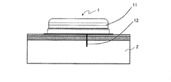
- FIG. 2 is a cross-sectional view of the sensor 1.
- the same components as those in FIG. 1 are designated by the same reference numerals.
- the senor 1 has a main body 11 and a probe 12.
- the probe 12 is inserted into the living body 2.
- the probe 12 has a reagent layer containing an oxidoreductase, and outputs an electric signal based on the glucose concentration to the main body 11.
- the main body 11 stores an electric signal based on the glucose concentration output from the probe 12 in a storage device, and transmits the electric signal to another device (not shown) at a predetermined timing.
- FIG. 3 is a plan view of the probe 12.
- FIG. 3A shows the entire probe 12.
- FIG. 3B shows an enlarged view of the tip portion of the probe 12 shown in FIG. 3A.
- the portion of the probe 12 region X1 (head of the probe 12) shown in FIG. 3A is housed in the main body 11.
- the tip portion of the probe 12 projects from the main body 11.
- the tip portion of the probe 12 is inserted into the living body 2.
- the arrow X2 shown in FIG. 3A indicates the direction in which the probe 12 is inserted into the living body 2.
- the probe 12 has a substrate 21, an electrode 22, a reagent layer 23, a reference layer 24, and a film 25.
- the manufacturing method of the probe 12 will be outlined.
- the electrode 22 is formed on the substrate 21.
- the substrate 21 is, for example, a sheet-shaped synthetic resin.
- the electrodes 22 are uniformly formed on the substrate 21.
- the material of the electrode 22 is, for example, gold (Au).
- the electrode 22 may be formed on the substrate 21 by, for example, sputtering.
- the electrode 22 may be referred to as an electrode film or an electrode layer.
- the electrode 22 is separated into three regions. Grooves A1 and A2 are formed in the electrodes 22 formed on the substrate 21, and the electrodes 22 are separated into three regions.
- the electrode 22 is separated into an working electrode 22a, a reference electrode 22b, and a counter electrode 22c by grooves A1 and A2.
- the grooves A1 and A2 may be formed by, for example, laser trimming.
- the working pole 22a may be referred to as a working pole membrane or working pole layer.
- the reference electrode 22b may be referred to as a reference electrode membrane or a reference electrode layer.
- the counter electrode 22c may be referred to as a counter electrode membrane or a counter electrode layer.
- the working electrode 22a has a potential (reference electrode) sufficient to oxidize, for example, a mediator (including hydrogen peroxide as well as an electronic mediator) reduced by a reaction of an analysis (glucose) with an oxidoreductase.
- a potential reference electrode
- Glucose concentration is measured by monitoring the current flowing between the working electrode 22a and the counter electrode 22c.
- the reference layer 24 is formed.
- a reference layer 24 is formed on the reference electrode 22b at the tip of the probe 12.
- the material of the reference layer 24 is, for example, silver / silver chloride (Ag / AgCl).
- the reference layer 24 may be formed by, for example, a screen printing method or a coating method using Ag / AgCl paste (ink).
- the reference layer 24 may be referred to as a reference membrane or a reference electrode.
- the film 25 is arranged and fixed.
- a film 25 having an opening is arranged on the working electrode 22a, the reference electrode 22b, the counter electrode 22c, and the reference layer 24 formed on the substrate 21.
- the film 25 is in the form of a sheet and has an insulating property.
- the film 25 is arranged so that the opening portion is located at the tip portion (the portion forming the reagent layer 23) of the probe 12. A reagent described later is dropped into the opening of the film 25.
- the film 25 may be referred to as a film layer, an insulating layer, or an insulating film. Arrangement may be paraphrased as stacking or placement.
- the film 25 has an opening so that the upper surface of the counter electrode 22c (the surface in the front side direction of the paper surface in FIG. 3) is partially exposed.
- the opening of the film 25 has a notch shape as shown in the region X3 of FIG. 3 (B) by the cutting step of (7) described later. Due to this notch shape, the counter electrode 22c is partially exposed on the upper surface.
- the upper surface may be regarded as the surface on the side where the reagent layer 23 of the probe 12 is formed.
- the film 25 has a shape in which the head portion of the probe 12 is partially exposed.
- the portion of region X4 in FIG. 3A is not covered by the film 25.
- the exposed electrode 22 in the region X4 is connected to the circuit of the main body 11.
- the upper surface of the reference layer 24 is covered with the film 25 as shown in FIG. 3B.
- the reference layer 24 is exposed in the width direction of the probe 12 (perpendicular to the insertion direction indicated by the arrow X2).
- the reference layer 24 is exposed on the right side surface of the tip portion of the probe 12 (see also the reference layer 24 of FIG. 4B).
- the reagent layer 23 is formed.
- a reagent layer 23 is formed on the working electrode 22a at the tip of the probe 12.
- the reagent is dropped into the opening of the film 25 described above and dried to form the reagent layer 23.
- the reagent layer 23 is not formed at the tip of the probe 12 shown by the arrow X5 in FIG. 3 (B).
- the reagent layer 23 is preferably formed away from the tip of the probe 12. That is, it is preferable that the reagent layer 23 is not formed over a predetermined distance from the tip of the probe 12. This is because by forming the reagent layer 23 away from the tip of the probe 12, it is possible to prevent the reagent layer 23 from peeling off (turning over) from the probe 12 when the probe 12 is inserted into the living body 2.
- the reagent layer 23 contains at least an oxidoreductase capable of a redox reaction with analite (glucose).
- the reagent layer 23 may be referred to as a reagent membrane, a working layer, or a working electrode.
- the opening of the film 25 may have, for example, a size and a shape in which a reagent layer 23 having a width larger than the width of the probe 12 is formed.
- the shape of the reagent layer 23 formed to be larger than the width of the probe 12 is shaped by the next trimming step.
- the reagent layer 23 and the electrode 22 are removed.
- the reagent layer 23 and the electrode 22 are trimmed along the insertion direction of the probe 12 at the end portion in the width direction of the probe 12 whose outer shape is formed by the cutting step (7) described later.
- the upper surface of the substrate 21 is partially exposed as shown in the region X6 of FIG. 3 (B).
- laser trimming may be used for trimming the reagent layer 23 and the electrode 22.
- the film 25 is also partially (slightly) trimmed at both ends in the insertion direction of the reagent layer 23.
- the probe 12 is cut out from the substrate 21 by cutting.
- the substrate 21 that has undergone the steps (1) to (6) above is cut, and the probe 12 having the shape shown in FIG. 3 (A) is cut out.
- the cutting position includes the trimmed part. For example, the vicinity of the center (near the center line) of the trimmed portion (bottom portion of the recess) is cut.
- the tip portion of the cut probe 12 is attached to, for example, a liquid forming a protective film to form a protective film.
- the protective film prevents or suppresses leakage of substances (mainly oxidoreductases and electron mediators) contained in the reagent layer 23 to the outside of the protective film.
- the protective film has pores through which the analite existing outside the protective film permeates into the protective film in which the reagent layer 23 is present.
- the protective film only needs to be able to protect (coat) at least the portion of the reagent layer 23 of the probe 12.
- FIG. 4A is a cross-sectional view taken along the line AA of FIG. As shown in FIG. 4A, in the portion of the probe 12 where the reagent layer 23 is formed, the working electrode 22a is formed on the substrate 21 (upper surface). The reagent layer 23 is formed on the working electrode 22a.
- the reagent layer 23 and the working electrode 22a are removed at both ends in the width direction (side surface of the probe 12) of the probe 12 by the trimming step of (6) above.
- the cutting step of (7) above the substrate 21 exposed by the trimming step of (6) above is cut at a position away from the reagent layer 23 and the working electrode 22a.
- the side surface of the probe 12 becomes stepped as shown by arrows 11a and 11b in FIG. 4A.
- a protective film is formed around the tip of the reagent layer 23 of the probe 12. In FIG. 4A, the protective film is not shown.
- FIG. 4B is a cross-sectional view taken along the line BB of FIG. As shown in FIG. 4B, in the portion where the reference layer 24 of the probe 12 is formed, the working electrode 22a and the reference electrode 22b are formed on the substrate 21. The working pole 22a and the reference pole 22b are physically and electrically separated by the groove A1.
- the reference layer 24 is formed on the reference pole 22b.
- the film 25 is arranged on the working electrode 22a, the reference electrode 22b, and the reference layer 24.
- the upper surface of the reference layer 24 is covered with the film 25, but is exposed on the side surface of the probe 12 (the right side surface in FIG. 4B).
- the film 25 above the reference layer 24 may be omitted. That is, the upper surface of the reference layer 24 may be exposed.
- FIG. 4C is a cross-sectional view taken along the line CC of FIG. As shown in FIG. 4C, in the portion where the upper surface of the counter electrode 22c is exposed, the working electrode 22a, the reference electrode 22b, and the counter electrode 22c are formed on the substrate 21.
- the working pole 22a and the reference pole 22b are physically and electrically separated by the groove A1.
- the reference electrode 22b and the counter electrode 22c are physically and electrically separated by the groove A2.
- a film 25 is formed on the working electrode 22a and the reference electrode 22b.
- the film 25 is not arranged on the counter electrode 22c, and the upper surface of the counter electrode 22c is exposed.
- the substrate 21 is a synthetic resin on a sheet.
- PET polyethylene terephthalate
- it is not particularly limited as long as it is a resin material such as a plastic material having at least one of the characteristics of flexibility, easy workability, and heat resistance.
- Other examples include general purpose plastics such as polyethylene, polypropylene, and polyethylene naphthalate.
- polyimide is preferable.
- Electrode 22 As described above, gold may be used as the material of the electrode 22. However, it is not particularly limited as long as it is a metal having conductivity and stability (for example, hard to oxidize or salt resistance) or a carbon material.
- examples of the material of the electrode 22 include platinum, palladium, and carbon.
- the metal material may be vapor-deposited (including sputtering) on the substrate 21.
- Other forming methods include printing, plating, spin coating and the like.
- carbon paste may be printed to form the electrode 22.
- different electrode materials may be used for the working electrode and the counter electrode.
- the reagent layer 23 contains at least an oxidoreductase capable of a redox reaction with analite. If the redox enzyme is a dehydrogenase, an electron mediator is further included. Further, the redox enzyme may be an oxidase (oxidase) or a system using an electron mediator. That is, if it is a system that electrochemically detects hydrogen peroxide generated by the redox reaction of glucose by an oxidase, an electron mediator is unnecessary, but it can also be detected electrochemically by using an electron mediator. In this case, the reagent layer 23 contains an electron mediator in addition to the oxidase.
- examples of redox enzymes include glucose oxidase and glucose dehydrogenase.
- glucose dehydrogenase flavin adenine dinucleotide (FAD) -linked glucose dehydrogenase is desirable from the viewpoint of low reactivity to maltose, and for example, enzymes derived from Aspergillus (Orize and Teres) and Mucor are preferable.
- FAD flavin adenine dinucleotide
- Examples of the electronic mediator include osmium complex, ruthenium complex, quinone compound, phenazine compound, ferrocene compound and the like. In addition, examples of the electronic mediator include derivatives of these.
- the reference layer 24 As the material of the reference layer 24, silver / silver chloride (Ag / AgCl) may be used as described above.
- the reference layer 24 may be formed by screen-printing or applying Ag / AgCl paste (ink) on the electrode 22 and then drying it.
- the senor 1 shows an example of a three-electrode configuration of an working electrode, a counter electrode, and a reference electrode that realizes more accurate measurement, even if it is a two-electrode configuration of the working electrode and the counter electrode. good.
- ⁇ Film 25 As the film 25, a sheet made of the same material as the substrate 21 to which an adhesive sheet (for example, acrylic type, rubber type, or hot melt type) is attached may be used. Further, a sheet made of a material different from that of the substrate 21 may be used. Further, the adhesive sheet alone may be used as the film 25. A thermal / thermoplastic resist film may be used as the film 25.
- an adhesive sheet for example, acrylic type, rubber type, or hot melt type
- the contact angle with the liquid on the film is preferably higher than the contact angle with the liquid at the opening, and the larger the difference, the more preferable.
- the temperature on the film is 90 ° or more and the opening is 50 ° or less. Even if the material does not have such a contact angle, it is possible to have the contact angle by applying at least one of a water-repellent treatment to the film surface and a hydrophilic treatment to the opening.
- the film 25 has a thickness of 1 ⁇ m or more and 150 ⁇ m or less, preferably 3 ⁇ m or more and 50 ⁇ m or less, and more preferably 5 ⁇ m or more and 30 ⁇ m or less.
- the film 25 may be formed by printing a resist ink.
- the protective film covering the surface of the reagent layer 23 has biocompatibility in which proteins and cells are not adsorbed or proteins and cells are not easily adsorbed.
- the protective film is preferably formed of a polymer having the above-mentioned properties.
- polymer examples include a copolymer of methyl methacrylate and hydroxyethyl methacrylate, a copolymer of butyl methacrylate and hydroxyethyl methacrylate, poly (2-methacryloyloxyethyl phosphorylcholine-con-butyl methacrylate) and the like.
- high molecular weight polymer examples include (meth) acrylate compounds having the same main chain as these exemplified polymers and having a reactive group capable of reacting with the linker in the side chain. It can also be used as an "ethylene-based polymer" having a methacryloyl group or an acryloyl group.
- FIG. 5 is a diagram for explaining the positional relationship between the reagent layer 23 and the film 25.
- FIG. 5 shows a plan view of the tip portion of the probe 12.
- the same components as those in FIG. 3 are designated by the same reference numerals.
- FIG. 5 shows a part of the manufacturing process of the probe 12.
- the “film formation” shown in FIG. 5 corresponds to the step (4) described above.
- “Applying the reagent solution” and “drying the applied reagent solution” correspond to the step (5) described above.
- “Trimming” corresponds to the step (6) described above.
- “Sensor cutting” corresponds to the step (7) described above.
- the “protective film formation” corresponds to the step (8) described above.
- FIG. 6 is a cross-sectional view taken along the line DD of FIG.
- a film 25 having an opening is arranged on the working electrode 22a. Then, the reagent is dropped onto the opening portion of the film 25 and dried. As a result, the reagent layer 23 is sandwiched and formed between the films 25 in the insertion direction of the probe 12, as shown in FIG. That is, the reagent layer 23 fits and is formed in the region defined by the opening of the film 25. In other words, the film 25 is adjacent to the reagent layer 23 on the electrode 22.
- the film 25 on the insertion direction side does not have to be formed.
- the film 25 on the left side shown in FIGS. 5 and 6 may be omitted.
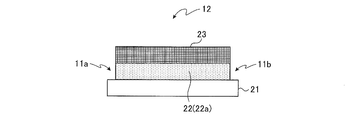
- FIG. 7 is a perspective view of the reagent layer 23 portion of the probe 12.
- the probe 12 faces the upper surface 31 on which the reagent layer 23 is formed, the back surface 32 facing the upper surface 31, the side surface 33 connecting the upper surface 31 and the back surface 32, and the side surface 33. It has a side surface 34 that connects the upper surface 31 and the back surface 32.
- the arrow X2 shown in FIG. 7 indicates the insertion direction of the probe 12 into the living body 2.
- the end of the upper surface 31 in the width direction of the probe 12 has stepped trimming portions 35 and 36 from which the reagent layer 23 and the electrode 22 have been removed.
- the trimming portions 35 and 36 are formed at least in a positional relationship in contact with the reagent layer 23.
- the reagent layer 23 extends from end to end in the width direction of the upper surface 31 to form the upper surface 31 of the probe 12 and forms a part of the side surface of the probe 12 (reagent layer of FIG. 4A). See also 23).
- the above sensor 1 may be regarded as having the following components.
- the sensor 1 has a main body 11 and a probe 12.
- the probe 12 is inserted into the living body 2 and acquires an electric signal for continuously or semi-continuously measuring the analyst.
- the substrate 21 has a first surface (for example, an upper surface 31) and a second surface (for example, a back surface 32) facing the first surface. Further, the substrate 21 has a third surface and a fourth surface (for example, side surfaces 33 and 34) of a surface that connects the first surface and the second surface and extends in the insertion direction of the probe 12.
- the working electrode 22a is formed on the first surface of the substrate 21 in the first electrode material.
- the reagent layer 23 is arranged in a part of the working electrode 22a.
- the trimming portions 35 and 36 are formed by removing the reagent layer 23 and the first electrode material at both ends of the first surface in a direction orthogonal to the direction in which the probe 12 is inserted into the living body 2. ..
- the reagent layer 23 contains an oxidoreductase.
- the trimming portions 35 and 36 are formed in a positional relationship of at least in contact with the reagent layer 23.
- the film 25 is adjacent to the reagent layer 23 in the direction of insertion into the living body 2 in the direction opposite to the tip end side of the probe 12.
- the reagent layer 23 does not have a portion sandwiched between the electrode 22 and the film 25.
- the film 25 is not placed on the reagent layer 23.
- the film 25 may or may not be adjacent to the reagent layer 23 on the distal end side of the probe 12. In other words, the film 25 may or may not be formed on the distal end side of the probe 12.
- the above sensor 1 may be regarded as having the following manufacturing process.
- a substrate 21 (substrate sheet) in which the working electrode 22a of the first electrode material is formed on the first surface is prepared.
- the reagent solution is dried to form the reagent layer 23.
- a predetermined position of the reagent layer 23 on the substrate 21 is trimmed to form a trimming portion from which the working electrode 22a formed under the reagent layer 23 and the reagent layer 23 has been removed.
- the substrate 21 is cut into a predetermined shape (the shape of the probe 12 shown in FIG. 3A, for example, the shape of a flagpole).
- the trimming portions 35 and 36 are included in the positions where the substrate 21 is cut.
- a protective film may be formed at the tip of the probe 12 on which the reagent layer 23 is formed.
- the protective film has pores that allow at least an analysis (glucose) to pass through.
- the counter electrode 22c may be formed on the first surface of the substrate 21 or may be formed on the second surface.
- Another counter electrode (second counter electrode) different from the counter electrode 22c may be formed on both or one of the first surface and the second surface of the substrate 21.
- the reference electrode 22b may be formed on at least one of the first to fourth surfaces.
- the film 25 may be arranged on the upper surface and the third surface side may be exposed.
- the reagent layer 23 does not have to be formed over a predetermined distance from the terminal side (tip of the probe 12) of the first surface in the insertion direction of the probe 12.
- a part (end) of the reagent layer 23 may be sandwiched between the electrode 22 and the film 25.
- the reagent layer 23 does not have to have a portion sandwiched between the electrode 22 and the film 25.
- the sensor 1 has a probe 12 inserted into the living body 2 and measures the analyst.
- the probe 12 has a substrate 21, an electrode 22 formed on the substrate 21, and a reagent layer 23 containing an oxidoreductase and formed on the electrode 22.
- the reagent layer 23 and the electrode 22 are trimmed along the insertion direction of the probe 12 into the living body 2.
- the variation in performance of the sensor 1 caused by the manufacturing process is suppressed.
- a uniform (uniform) portion in the ring is used as the reagent layer 23 by trimming. Available.
- the cutting edge when cutting into the probe 12 shape, the cutting edge can be prevented from coming into contact with the reagent layer 23, and cracking of the reagent layer 23 can be reduced.
- the cutting edge when cutting into the probe 12 shape, the cutting edge can be prevented from coming into contact with the reagent layer 23, and contamination of the reagent can be suppressed.
- the probe 12 included in the sensor 1 has a step of forming the electrode 22 on the substrate 21, a step of forming the reagent layer 23 containing the oxidoreductase on the electrode 22, and the width of the probe 12.
- Manufactured by a step of trimming the reagent layer 23 and the electrode 22 along the insertion direction of the probe 12 into the living body 2 at at least one end in the direction.
- the variation in performance of the sensor 1 caused by the manufacturing process is suppressed.
- a uniform (uniform) central portion in the ring can be used as the reagent layer 23 by trimming.
- the cutting edge when cutting into the shape of the probe 12, the cutting edge can be prevented from coming into contact with the reagent layer 23 by trimming, so that cracking of the reagent layer 23 can be reduced. In addition, contamination of reagents can be suppressed.
- the film 25 is arranged on the electrode 22 so as to be adjacent to the reagent layer 23 at both ends in the insertion direction of the reagent layer 23.
- the film 25 can determine the position where the reagent is dropped, and a uniform reagent layer 23 can be formed before trimming.
- the probe 12 may have a trimming section at one end in the width direction. That is, the number of trimming portions may be one.
- FIG. 8 is a plan view of the tip portion of the probe 12.
- the same components as those in FIG. 3 are designated by the same reference numerals.
- FIG. 8 shows an example in which the working electrode 22a and the counter electrode 22c are formed side by side in the width direction of the probe 12. In FIG. 8, the film 25 is not shown.
- the reagent layer 23 is formed so as to straddle the width of the probe 12 on one end side in the width direction of the probe 12.
- the reagent layer 23 is formed on the other end side in the width direction of the probe 12 so as not to straddle the width of the probe 12.
- the reagent layer 23 is formed so as to straddle the right end of the probe 12 and not to straddle the left end of the probe 12.
- the probe 12 has a trimming portion 41.
- the trimming portion 41 is formed on the side where the reagent layer 23 straddles the width of the probe (on the right side in FIG. 6).
- the trimming portion 41 is formed by trimming the reagent layer 23 and the working electrode 22a.
- the trimming section 41 exposes the substrate 21.
- the probe 12 may have a trimming portion at one end in the width direction. This also suppresses the variation in performance of the sensor 1 caused by the manufacturing process.
- the reagent layer 23 may protrude outside the region defined by the film 25 in the insertion direction of the probe 12.
- FIG. 9 is a diagram for explaining the positional relationship between the reagent layer 23 and the film 25.
- FIG. 9 shows a plan view of the tip portion of the probe 12.
- the same components as those in FIG. 3 are designated by the same reference numerals.
- FIG. 9 shows a part of the manufacturing process of the probe 12.
- “Applying the reagent solution” and “drying the applied reagent solution” shown in FIG. 9 correspond to the step (5) described above.
- the “film formation” corresponds to the step (4) described above.
- “Trimming” corresponds to the step (6) described above.
- “Sensor cutting” corresponds to the step (7) described above.
- the “protective film formation” corresponds to the step (8) described above.
- FIG. 10 is a cross-sectional view taken along the line EE of FIG.
- a film 25 having an opening is arranged on the reagent layer 23.
- the film 25 is arranged so that the opening portion is located in the reagent layer 23.
- the openings of the film 25 are formed so as to overlap the reagent layer 23 at both ends of the reagent layer 23 in the insertion direction (direction of arrow X2). That is, a part of the film 25 overlaps the reagent layer 23 at both ends of the reagent layer 23 in the insertion direction. Further, a part of the film 25 overlaps the trimming portion at both ends in the insertion direction of the trimming portion.
- the film 25 on the insertion direction side does not have to be formed.
- the film 25 on the left side shown in FIGS. 9 and 10 may be omitted.
- the film 25 is arranged on the electrode 22 so as to overlap the reagent layer 23 and the trimming portion at both ends of the reagent layer 23 in the insertion direction.
- the variation in performance of the sensor 1 caused by the manufacturing process is suppressed.
- the end portion (edge portion of the coffee ring) of the reagent layer 23 in the insertion direction of the probe 12 can be covered with the film 25 to expose a uniform portion of the reagent layer 23.
- FIG. 11 is a diagram showing an example of the opening shape of the film 25.
- the hatched portions of FIGS. 11A and 11B indicate trimming portions.
- the figures such as the polygonal shape and the round shape shown in (A) of FIG. 11 and (B) of FIG. 11 indicate the shape of the opening portion of the film 25.
- the arrow X2 shown in FIG. 11 indicates the direction in which the probe 12 is inserted into the living body 2.
- films 25 are formed at both ends of the reagent layer 23 in the insertion direction (see, for example, FIGS. 5 and 6).
- a film 25 is formed at the end of the reagent layer 23 opposite to the tip end side (for example, the film 25 on the right side of FIGS. 5 and 6 is formed, and the film 25 on the left side is formed. Not done).
- the opening shape of the film 25 may have various shapes.
- FIG. 12 is a diagram illustrating an example of the size of the sensor 1.
- the same components as those in FIGS. 3 and 7 are designated by the same reference numerals.
- the film 25 is not shown.
- the width D1 of the tip portion of the probe 12 is, for example, 70 ⁇ m or more and 1700 ⁇ m or less.
- the width D1 is 70 ⁇ m or more and 600 ⁇ m or less, more preferably 70 ⁇ m or more and 400 ⁇ m or less.
- the width D2 of the trimming portions 35 and 36 is, for example, 5 ⁇ m or more.
- the width D2 is not particularly limited as long as it has a width that can secure the reagent layer 23 with respect to the width of the tip portion of the probe 12.
- it can be realized by irradiating the laser a plurality of times.
- an electrochemical sensor such as a CGM sensor
- the signal intensity obtained from the probe may differ depending on the measurement timing such as day or time, even if the analysis concentration is the same, and the measurement accuracy of the sensor is lowered.
- the present inventors have decomposed Ag / AgCl (silver or silver chloride) which is a material of the reference layer by continuously energizing the reference layer for a long period of time, and the decomposed Ag / AgCl. Is thought to be due to the inflow to the working electrode side. Then, the present inventors presume that the cause of the abnormal signal value caused by the inflow of Ag / AgCl to the working electrode side is that silver ion or chloride ion reacts with the reagent on the working electrode side. ing. Therefore, if the decomposition of Ag / AgCl in the reference layer is suppressed, the deterioration of the measurement accuracy of the sensor can be suppressed.
- Ag / AgCl silver or silver chloride
- One means of suppressing the decomposition of Ag / AgCl in the reference layer is to miniaturize the reference layer and reduce the area in contact with the analyst.
- Examples of the method for forming the reference layer of Ag / AgCl include a screen printing method and a coating method.
- the screen printing method when microelectrodes are formed by the screen printing method, the printing plate is likely to be clogged due to the microelectrodes.
- the screen printing method has a large loss of Ag / AgCl paste. Therefore, the screen printing method is not suitable from the viewpoint of mass production of sensors.
- the plating method is a preferable method from the viewpoint of miniaturization of the Ag / AgCl electrode (reference layer), but it is not suitable for mass production of sensors.
- the first reason is that the management of chemicals used for plating and the manufacturing process is complicated.
- the Ag / AgCl electrode it is difficult to mask the probe portion other than the minute Ag / AgCl electrode and to continuously manage the probe portion.
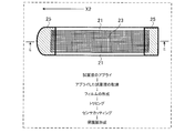
- FIG. 13 is a perspective view of the probe 12 of the sensor 1 according to the second embodiment.
- the same components as those in FIGS. 2 and 3 are designated by the same reference numerals.
- the probe 12 shown in FIG. 13 has an electrode 22 like the probe 12 described in the first embodiment. Further, the probe 12 includes a reagent layer 23 (not shown in FIG. 13) and a reference layer 24 (not shown in FIG. 13), similarly to the probe 12 described in the first embodiment. The first surface has a counter electrode 22c (not shown in FIG. 13), which is partially exposed.
- the surface of the probe 12 on which the reagent layer 23 and the reference layer 24 are formed may be referred to as a first surface.
- the surface facing the first surface may be referred to as a second surface.
- a surface that connects the first surface and the second surface and extends in the insertion direction of the probe 12 (direction of arrow X2 in FIG. 13), and the surface on the right side when viewed from the tip of the probe 12 is the third surface. May be called.
- a surface that connects the first surface and the second surface and extends in the insertion direction of the probe 12, and the surface on the left side when viewed from the tip of the probe 12 may be referred to as a fourth surface.
- the first surface may be referred to as the upper surface.
- the second surface may be referred to as the bottom surface.
- the third and fourth surfaces may be referred to as side surfaces.
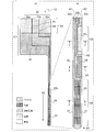
- FIG. 14 is a partial side view of the probe 12 of FIG. 13 as viewed from the third surface side. As shown in FIG. 14, an electrode 22 is formed on the first surface side of the substrate 21.
- the electrode 22 has an working electrode 22a, a reference electrode 22b, and a counter electrode 22c.
- a reagent layer 23 is formed on the first surface side of the working electrode 22a of the electrode 22.
- a reference layer 24 is formed on the first surface side of the reference electrode 22b of the electrode 22.
- the reference layer 24 is formed by curing the Ag / AgCl paste applied on the reference electrode 22b.
- the first surface side of the reference layer 24 is covered with the film 25. In other words, the first surface side of the reference layer 24 is not exposed.
- the reference layer 24 is exposed on the third surface side of the probe 12. In other words, the reference layer 24 is exposed in the width direction of the probe 12 (perpendicular to the insertion direction indicated by the arrow X2) (see also FIG. 4B).
- the reference layer 24 exposed on the third surface side may be covered with a protective film as described in the first embodiment.
- the protective film has pores that allow at least an analyze (glucose) to pass through. Therefore, the reference layer 24 is exposed (contacted, energized) to at least the analyze.
- the film 25 has an opening so that the portion in the region X3 on the first surface side of the counter electrode 22c is exposed.
- the opening of the film 25 has a notch shape (see also region X3 in FIG. 3B). Due to this notch shape, the counter electrode 22c is partially exposed on the upper surface.
- the shape of the reference layer 24 in the direction from the third surface to the fourth surface as viewed from the first surface side may have an arc shape, an elliptical arc shape, or the like (see, for example, FIG. 15).
- the portion of the working pole 22a from the head of the probe 12 (the portion of the region X1 in FIG. 13) to the reagent layer 23 may be referred to as a lead or a working pole lead.
- the portion of the reference electrode 22b from the head of the probe 12 to the reference layer 24 may be referred to as a lead or a reference electrode lead.
- the portion of the counter electrode 22c from the head of the probe 12 to the opening (region X3) of the film 25 may be referred to as a lead or counter electrode lead.
- the reference layer 24 may be exposed on the fourth surface side. Further, the reference layer 24 and the counter electrode 22c may be formed on the second surface side. When the reference layer 24 and the counter electrode 22c are formed on the second surface side, the reference electrode lead and the counter electrode lead are formed on the second surface side.
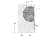
- FIG. 15 is a diagram illustrating a shape example of the reference layer 24.
- (A) of FIG. 15 and (B) of FIG. 15 show the reference layer 24 when the probe 12 is viewed from the first surface side.
- the film 25 is not shown.
- 15 (A) and 15 (B) show grooves A1 and A2 that separate the working electrode 22a, the reference electrode 22b, and the counter electrode 22c of the electrode 22 (see also FIG. 3B). ).
- the shape of the reference layer 24 in the direction from the third surface to the fourth surface when the probe 12 is viewed from the first surface side may have an arc shape. Further, the shape of the reference layer 24 in the direction from the third surface to the fourth surface when the probe 12 is viewed from the first surface side may have an elliptical arc shape. In other words, the shape of the reference layer 24 is in the direction (third surface) from the surface where the reference layer 24 is exposed (third surface) toward the central portion (inside) of the reference layer 24 when viewed from the first surface side. It may have a constricted shape in the direction from the fourth surface to the fourth surface).
- the reference layer 24 may have a shape in which a plurality of arcs or elliptical arcs are continuous.
- the reference layer 24 may have a shape in which two arcs are continuous. That is, the reference layer 24 may have a first arc and a second arc or a first elliptical arc and a second elliptical arc. Further, the reference layer 24 may have a shape in which an arc and an elliptical arc are combined.
- the reference pole 22b (reference pole lead) has a wider width (area) on the tip side of the probe 12.
- Ag / AgCl paste is applied to a part of the widened region of the reference electrode lead.
- Step 1 The electrode 22 is formed on the first surface side of the sheet-shaped substrate 21.
- Step 2 Apply Ag / AgCl paste to a predetermined position on the electrode 22.
- Step 3 Dry the applied Ag / AgCl paste.
- Step 4 A film 25 is formed on a portion containing dried Ag / AgCl.
- Step 5 The sheet-shaped substrate 21 is cut into a probe shape. When cutting, cut so as to include a part of dried Ag / AgCl.
- next step 1a may be continued after the step 1. Then, instead of the step 2, the next step 2a may be performed.
- Step 1a Grooves A1 and A2 are formed in the electrode 22 formed on the substrate 21, and the working electrode 22a, the reference electrode 22b, and the counter electrode 22c are formed.
- Step 2a The Ag / AgCl paste is applied to a predetermined position of the reference electrode 22b formed in the step 1a.
- Ag / AgCl paste is applied to a part of the region of the reference electrode 22b (reference electrode lead) having a wider width on the tip side of the probe 12.
- step 2 may be performed as in the following step 2b.
- Step 2b When the Ag / AgCl paste is applied to the first surface side of the sheet-shaped substrate 21, a part of Ag / AgCl is applied so as to include the reference electrode 22b (reference electrode lead) portion. In other words, the Ag / AgCl paste is applied so as to straddle the portion where the substrate 21 is cut in the cutting in step 5.
- FIG. 16 is a diagram showing an application example of Ag / AgCl paste 51.
- FIG. 16 shows electrodes 22 (reference numerals omitted in FIG. 16), grooves A1 and A2, and Ag / AgCl paste 51 formed on the substrate 21.
- the dotted line X11 shown in FIG. 16 indicates a portion to be cut in the step 5.
- the head, tip, reagent layer 23, and film 25 of the probe 12 are not shown.
- the Ag / AgCl paste 51 is applied to the end portion of the reference electrode 22b (the portion where the width of the reference electrode 22b is widened) in the insertion direction of the probe 12. Further, the Ag / AgCl paste 51 is applied so as to straddle the portion (dotted line X11) where the substrate 21 is cut in the cutting of the step 5. Therefore, in step 5, the substrate 21 is cut so as to straddle the portion to which the Ag / AgCl paste 51 is applied.
- step 4 the film 25 is formed on the upper surface of the Ag / AgCl paste 51. Therefore, as described with reference to FIG. 14, the reference layer 24 is not exposed on the upper surface (first surface) of the probe 12, but is exposed on the side surface (third surface).
- FIG. 17 is a side view of the Ag / AgCl paste 51 after application.
- FIG. 17 shows the substrate 21, the electrode 22, and the Ag / AgCl paste 51.
- the coating method is suitable for forming microelectrodes (Ag / AgCl reference layer 24).
- the surface of the reference layer 24 formed by the coating method does not have a flat surface on the surface of the reference layer 24 and has a large surface area.
- the Ag / AgCl paste 51 may have corners (swelling) on the surface as shown in the Ag / AgCl paste 51 on the right side (note that the corners may be removed by cutting in step 5).
- the surface area of the Ag / AgCl paste 51 tends to vary widely.
- the senor 1 can measure the analyst with high accuracy. Further, the sensor 1 can be easily mass-produced.
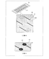
- 18A-18C are diagrams illustrating an example of a method for manufacturing the probe 12.
- the electrode 22 is formed on the sheet-shaped substrate 21.
- an electrode material such as gold is sputtered onto a sheet-shaped substrate 21 such as polyethylene terephthalate (PET) to form an electrode 22.
- PET polyethylene terephthalate
- Step 12 As shown in (Step 12) of FIG. 18A, the electrode 22 is trimmed to form the working electrode 22a, the reference electrode 22b, and the counter electrode 22c (reference numerals are omitted in (Step 12) of FIG. 18A).
- the trimming of the electrode 22 for example, laser trimming may be used.
- Step 13 As shown in FIG. 18A (step 13), Ag / AgCl paste 51 is applied onto the reference electrode 22b across the cut portion (cut line) of the substrate 21 and dried. In other words, Ag / AgCl paste 51 is applied and dried so as to straddle the reference electrode 22b and the portion outside the probe 12 when finally cut. As a result, the reference layer 24 is formed on the electrode 22 (reference electrode 22b).
- FIG. 18A is an enlarged view of the dotted line frame A21 portion of FIG. 18A (process 12), which is the same as FIG. In FIG. 18A (step 13), reference poles 22b, grooves A1 and A2, and Ag / AgCl paste 51 formed on the substrate 21 are shown. In FIG. 18A (step 13), the head, tip, reagent layer 23, and film 25 of the probe 12 are not shown.
- Step 14 As shown in FIG. 18B (step 14), a film 25 having an opening of a portion where the reagent layer 23 of the working electrode 22a is formed and a portion corresponding to the region X3 (see FIG. 14) of the counter electrode 22c is used as a substrate. Paste on 21. At this time, the reference pole 22b (reference layer 24) on the first surface side is covered with the film 25 (see FIG. 14).
- the arrow A22 in FIG. 18B indicates the opening of the film 25 in the portion where the reagent layer 23 is formed.
- the opening of the film 25 in the portion corresponding to the region X3 (see FIG. 14) of the counter electrode 22c is not shown.
- Step 15 As shown in (Step 15) of FIG. 18B, the reagent solution is applied to the opening portion of the film 25 for forming the reagent layer 23 (the portion of arrow A22 shown in (Step 14) of FIG. 18B) and dried. The reagent layer 23 is formed.
- the substrate 21 is cut into the shape of the probe 12 so as to include a part of the reagent layer 23 and a part of the Ag / AgCl paste 51.
- the reference layer 24 is covered with the film 25 on the first surface side of the probe 12, but is exposed on the third surface side.
- Step 17 As shown in FIG. 18C (step 17), for example, at least the reagent layer 23 portion of the probe 12 is covered with a protective film by a dip.
- FIG. 19 is a diagram illustrating the application of Ag / AgCl paste 51.
- FIG. 19 shows a part of the substrate 21 on which the electrode 22 is formed and the coating device 61.
- the coating device 61 has a nozzle 62.
- the Ag / AgCl paste 51 is discharged from the nozzle 62 and applied onto the reference electrode 22b.
- FIG. 20 is a diagram illustrating the shape of the Ag / AgCl paste 51 after application.
- the Ag / AgCl paste 51 applied to the substrate 21 may have a circular shape or an elliptical shape.
- the Ag / AgCl paste 51 may have a blowout shape.
- the blowout shape is formed by, for example, the squeegee method described later.
- the dotted line A31 shown in FIG. 20 shows, for example, the cut line of the cut performed in the above-mentioned step 16. Therefore, the outer peripheral shape of the reference layer 24 when viewed from the upper surface side has an arc shape, an elliptical arc shape, a shape obtained by cutting the blowout shape in half by cutting the substrate 21, and the like (for example, FIG. 23 (A), FIG. 24 (A) and 25 (A)).
- FIG. 21 is a diagram illustrating the operation of the coating device 61. As shown in FIG. 21 (A), the coating device 61 is moved to the vicinity of the substrate 21. Then, the coating device 61 discharges the Ag / AgCl paste 51 from the nozzle 62.
- the coating device 61 rises as shown in (B) of FIG. 21 and (C) of FIG. 21.
- the Ag / AgCl paste 51 is applied onto the reference electrode 22b of the substrate 21.
- one Ag / AgCl paste 51 is coated on the reference electrode 22b of the substrate 21 (for example). , (A), (B) of FIG. 20).
- the method of applying one Ag / AgCl paste 51 on the reference electrode 22b of the substrate 21 may be referred to as a single-shot method.
- two or more Ag / AgCl pastes 51 are coated on the reference electrode 22b of the substrate 21.
- a method of applying two or more Ag / AgCl pastes 51 on the reference electrode 22b of the substrate 21 may be referred to as a continuous method.
- FIG. 22 is a diagram illustrating the operation of the coating device 61. As shown in FIG. 22 (A), the coating device 61 is moved to the vicinity of the substrate 21. Then, the coating device 61 discharges the Ag / AgCl paste 51 from the nozzle 62.
- the coating device 61 moves in parallel while maintaining the distance from the substrate 21.
- the Ag / AgCl paste 51 is applied on the reference electrode 22b of the substrate 21 so as to have a blowout shape, as shown in FIG. 20 (E).
- the method of moving the coating device 61 in parallel while maintaining the distance from the substrate 21 and applying the Ag / AgCl paste 51 on the substrate 21 may be referred to as a squeegee method.
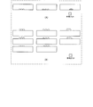
- FIG. 23 is a diagram showing a shape example of the reference layer 24 by the single-engine construction method.
- FIG. 23A shows an example of the shape of the reference layer 24 as viewed from the first surface side of the probe 12 after the substrate 21 has been cut.
- FIG. 23 (B) shows a shape example of the reference layer 24 seen from the third surface side of the probe 12 after the substrate 21 is cut.
- the reference layer 24 may be formed in an arc shape when viewed from the first surface side of the probe 12.
- the reference layer 24 may be an arc having a central angle of 180 ° (semicircle). Further, the reference layer 24 may be an arc having a central angle larger than 180 °. Further, the reference layer 24 may be an arc whose central angle is smaller than 180 °. Further, the reference layer 24 may be formed in an elliptical arc shape, a quadrangular shape, or a triangular shape.
- the reference layer 24 has an arc shape, an elliptical arc shape, an arc shape or an elliptical arc shape having a corner at the center, and a peripheral corner when viewed from the third surface side of the probe 12. It may be formed in a shape or a quadrangular shape.
- the shape of the reference layer 24 can be set to various shapes depending on the shape of the nozzle 62 of the coating device 61.
- the shape having a corner around (B) in FIG. 23 is not a nozzle shape but is formed by a spotting method.
- FIG. 24 is a diagram showing a shape example of the reference layer 24 by the continuous construction method.
- FIG. 24A shows an example of the shape of the reference layer 24 as viewed from the first surface side of the probe 12 after the substrate 21 has been cut.
- FIG. 24B shows an example of the shape of the reference layer 24 as viewed from the third surface side of the probe 12 after the substrate 21 is cut.
- the reference layer 24 may be formed in an arc shape when viewed from the first surface side of the probe 12.
- the reference layers 24 may be adjacent or separated. Further, the reference layers 24 may overlap.
- the shape of the reference layer 24 is not limited to the arc shape, and may be an elliptical arc shape, a quadrangular shape, or a triangular shape.
- the reference layer 24 has an arc shape, an elliptical arc shape, an arc shape or an elliptical arc shape having an angle, and a shape having an angle at the center when viewed from the third surface side of the probe 12.
- it may be formed in a quadrangular shape.
- the shape of the reference layer 24 can be set to various shapes depending on the shape of the nozzle 62 of the coating device 61.
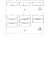
- FIG. 25 is a diagram showing a shape example of the reference layer 24 by the squeegee method.
- FIG. 25A shows an example of the shape of the reference layer 24 as viewed from the first surface side of the probe 12 after the substrate 21 is cut.
- FIG. 25B shows an example of the shape of the reference layer 24 as viewed from the third surface side of the probe 12 after the substrate 21 is cut.
- the reference layer 24 may be formed in a shape obtained by halving the blowout shape when viewed from the first surface side of the probe 12. Further, the reference layer 24 may have a plurality of shapes in which the shape of the balloon is halved.
- the reference layer 24 may be formed in a shape obtained by halving the blowout shape when viewed from the third surface side of the probe 12.
- the reference layer 24 may have an angle on a part of the upper surface in a shape obtained by halving the shape of the blowout. Further, the reference layer 24 may be formed in a quadrangular shape when viewed from the third surface side of the probe 12.
- the Ag / AgCl paste 51 will be described.
- the Ag / AgCl paste 51 may have a viscosity in the range of 0.1 Pa ⁇ s or more and 300 Pa ⁇ s or less, for example. More preferably, the Ag / AgCl paste 51 may have a viscosity in the range of 1 Pa ⁇ s or more and 100 Pa ⁇ s or less. More preferably, the Ag / AgCl paste 51 may have a viscosity in the range of 10 Pa ⁇ s or more and 50 Pa ⁇ S or less.
- an organic solvent such as thinner containing toluene, xylene, ethyl acetate, butyl acetate or acetone as a main component may be used.
- the exposure size of the reference layer 24 will be described.
- the height of the exposed surface of the reference layer 24 may be, for example, in the range of 1 ⁇ m or more and 200 ⁇ m or less from the viewpoint of suppressing decomposition of the reference layer 24 over a long period of time. More preferably, the height of the exposed surface of the reference layer 24 may be in the range of 2 ⁇ m or more and 50 ⁇ m or less. More preferably, the height of the exposed surface of the reference layer 24 may be in the range of 5 ⁇ m or more and 15 ⁇ m or less.
- the width of the exposed surface of the reference layer 24 may be, for example, in the range of 1 ⁇ m or more and 1000 ⁇ m or less. More preferably, the width of the exposed surface of the reference layer 24 may be in the range of 50 ⁇ m or more and 800 ⁇ m or less. More preferably, the width of the exposed surface of the reference layer 24 may be in the range of 100 ⁇ m or more and 600 ⁇ m or less.
- the exposed area of the reference layer 24 is, for example, may range from 0.5 [mu] m 2 or more 160000Myuemu 2 or less. More preferably, the exposed area of the reference layer 24 may be in the range of 70 [mu] m 2 or more 32000Myuemu 2 or less. More preferably, the exposed area of the reference layer 24 may be in the range of 390 ⁇ m 2 or more and 7100 ⁇ m 2 or less.
- the probe 12 of the sensor 1 inserted into the living body and measuring the analyze includes the substrate 21, the electrode 22 formed on the substrate 21, and the reference layer 24 formed on the electrode 22. Has. The first surface of the reference layer 24 is covered with the film 25, and the third surface is exposed.
- the first surface of the reference layer 24 is covered with the film 25 and exposed on the third surface, the area of the reference layer 24 in contact with the analysts can be reduced, and the reference layer 24 is decomposed (Ag / Ag /). (Degradation of AgCl) is suppressed. Therefore, the sensor 1 can measure the analyst with higher accuracy.
- the reference layer 24 is coated on the electrode 22 by a coating method, and has a narrowed shape in the direction from the third surface toward the inside of the reference layer 24. As a result, the reference layer 24 can be stably microformed on the first surface by the coating method.
- the reference layer 24 can be more microformed.
- the reference layer 24 is formed on the electrode 22 by the coating method, it may be formed by the screen printing method. Further, in the coating method and the screen printing method, it is preferable to form the reference layer 24 by the coating method. The reason is that in the screen printing method, the loss of the material (Ag / AgCl) is large, and it is necessary to take measures against clogging of the Ag / AgCl paste of the screen printing plate, which complicates the manufacturing control. Is.
- each component in the embodiment may be arbitrarily combined as long as the purpose of the present disclosure is not deviated.
- the probe 12 described in the second embodiment may have a trimming portion formed in the same manner as the probe 12 described in the first embodiment.
- the probe 12 described in the second embodiment may have a protective film for coating the reagent layer 23.
- a part of the film 25 may be overlapped on the reagent layer 23 at both ends in the insertion direction of the reagent layer 23. .. Further, the film 25 on the insertion direction side does not have to be formed.
- each component of the probe 12 described in the second embodiment the same material as the material of each component of the probe 12 described in the first embodiment may be used. Further, the size of the probe 12 described in the second embodiment may be the same as that of the probe 12 described in the first embodiment.
- the present disclosure is useful for biosensors, such as CGM sensors.
Landscapes
- Health & Medical Sciences (AREA)
- Life Sciences & Earth Sciences (AREA)
- Physics & Mathematics (AREA)
- Biomedical Technology (AREA)
- Medical Informatics (AREA)
- Veterinary Medicine (AREA)
- Public Health (AREA)
- Biophysics (AREA)
- Pathology (AREA)
- Engineering & Computer Science (AREA)
- General Health & Medical Sciences (AREA)
- Heart & Thoracic Surgery (AREA)
- Animal Behavior & Ethology (AREA)
- Molecular Biology (AREA)
- Surgery (AREA)
- Optics & Photonics (AREA)
- Chemical & Material Sciences (AREA)
- Chemical Kinetics & Catalysis (AREA)
- General Chemical & Material Sciences (AREA)
- Emergency Medicine (AREA)
- Measurement Of The Respiration, Hearing Ability, Form, And Blood Characteristics Of Living Organisms (AREA)
- Apparatus Associated With Microorganisms And Enzymes (AREA)
Priority Applications (4)
| Application Number | Priority Date | Filing Date | Title |
|---|---|---|---|
| US17/799,432 US20230069504A1 (en) | 2020-02-28 | 2021-02-26 | Sensor and method for manufacturing same |
| JP2022503366A JP7362890B2 (ja) | 2020-02-28 | 2021-02-26 | センサーおよびその製造方法 |
| CN202180016589.2A CN115175614A (zh) | 2020-02-28 | 2021-02-26 | 传感器及其制造方法 |
| EP21761536.8A EP4111969B1 (en) | 2020-02-28 | 2021-02-26 | Sensor and method for manufacturing same |
Applications Claiming Priority (2)
| Application Number | Priority Date | Filing Date | Title |
|---|---|---|---|
| US202062982939P | 2020-02-28 | 2020-02-28 | |
| US62/982,939 | 2020-02-28 |
Publications (1)
| Publication Number | Publication Date |
|---|---|
| WO2021172561A1 true WO2021172561A1 (ja) | 2021-09-02 |
Family
ID=77491935
Family Applications (1)
| Application Number | Title | Priority Date | Filing Date |
|---|---|---|---|
| PCT/JP2021/007510 Ceased WO2021172561A1 (ja) | 2020-02-28 | 2021-02-26 | センサーおよびその製造方法 |
Country Status (5)
| Country | Link |
|---|---|
| US (1) | US20230069504A1 (https=) |
| EP (1) | EP4111969B1 (https=) |
| JP (1) | JP7362890B2 (https=) |
| CN (1) | CN115175614A (https=) |
| WO (1) | WO2021172561A1 (https=) |
Citations (4)
| Publication number | Priority date | Publication date | Assignee | Title |
|---|---|---|---|---|
| WO2017187943A1 (ja) * | 2016-04-27 | 2017-11-02 | パナソニックヘルスケアホールディングス株式会社 | センサ挿入装置およびバイオセンサ |
| WO2019006413A1 (en) * | 2017-06-30 | 2019-01-03 | Abbott Diabetes Care | METHOD AND APPARATUS FOR ANALYTE DETECTION USING ELECTROCHEMICAL BIOSENSOR |
| JP2019514615A (ja) * | 2016-05-13 | 2019-06-06 | パーキュセンス | 被検物質センサー |
| JP2019170701A (ja) * | 2018-03-28 | 2019-10-10 | Phcホールディングス株式会社 | 検体応答性酵素の外部への流出を防止する保護膜およびそのような保護膜が形成されたバイオセンサープローブ |
Family Cites Families (7)
| Publication number | Priority date | Publication date | Assignee | Title |
|---|---|---|---|---|
| JP3907584B2 (ja) * | 2002-12-27 | 2007-04-18 | 日機装株式会社 | 糖検出電極装置 |
| FI3912551T3 (fi) * | 2009-02-26 | 2023-10-31 | Abbott Diabetes Care Inc | Parannettuja analyyttiantureita ja menetelmiä niiden valmistamiseksi ja käyttämiseksi |
| US9215995B2 (en) * | 2010-06-23 | 2015-12-22 | Medtronic Minimed, Inc. | Sensor systems having multiple probes and electrode arrays |
| CN105411607B (zh) * | 2015-11-16 | 2017-03-01 | 杭州亿信网络科技有限公司 | 皮下组织介入式葡萄糖微型传感器及其制备方法 |
| EP3747364A4 (en) * | 2018-01-29 | 2021-11-10 | PHC Holdings Corporation | PROTECTIVE FILM MATERIAL FOR BIOCAPTER PROBE |
| US20190310219A1 (en) * | 2018-04-06 | 2019-10-10 | Zense-Life Inc. | Enhanced interference membrane for a working electrode of a continuous biological sensor |
| CN109406589B (zh) * | 2018-11-23 | 2023-07-21 | 浙江大学 | 一种植入式血糖测试探针及其基于丝网印刷的制作方法 |
-
2021
- 2021-02-26 EP EP21761536.8A patent/EP4111969B1/en active Active
- 2021-02-26 US US17/799,432 patent/US20230069504A1/en active Pending
- 2021-02-26 WO PCT/JP2021/007510 patent/WO2021172561A1/ja not_active Ceased
- 2021-02-26 JP JP2022503366A patent/JP7362890B2/ja active Active
- 2021-02-26 CN CN202180016589.2A patent/CN115175614A/zh active Pending
Patent Citations (4)
| Publication number | Priority date | Publication date | Assignee | Title |
|---|---|---|---|---|
| WO2017187943A1 (ja) * | 2016-04-27 | 2017-11-02 | パナソニックヘルスケアホールディングス株式会社 | センサ挿入装置およびバイオセンサ |
| JP2019514615A (ja) * | 2016-05-13 | 2019-06-06 | パーキュセンス | 被検物質センサー |
| WO2019006413A1 (en) * | 2017-06-30 | 2019-01-03 | Abbott Diabetes Care | METHOD AND APPARATUS FOR ANALYTE DETECTION USING ELECTROCHEMICAL BIOSENSOR |
| JP2019170701A (ja) * | 2018-03-28 | 2019-10-10 | Phcホールディングス株式会社 | 検体応答性酵素の外部への流出を防止する保護膜およびそのような保護膜が形成されたバイオセンサープローブ |
Non-Patent Citations (1)
| Title |
|---|
| See also references of EP4111969A4 |
Also Published As
| Publication number | Publication date |
|---|---|
| US20230069504A1 (en) | 2023-03-02 |
| EP4111969B1 (en) | 2026-04-08 |
| CN115175614A (zh) | 2022-10-11 |
| EP4111969A1 (en) | 2023-01-04 |
| JP7362890B2 (ja) | 2023-10-17 |
| JPWO2021172561A1 (https=) | 2021-09-02 |
| EP4111969A4 (en) | 2024-04-03 |
Similar Documents
| Publication | Publication Date | Title |
|---|---|---|
| JP4696183B2 (ja) | 血液成分の測定方法、それに用いるバイオセンサおよび測定装置 | |
| CN100472210C (zh) | 血液成分的测定方法及该方法中使用的传感器和测定装置 | |
| CN101052727A (zh) | 用于测定生理或水性液体中被分析物浓度的被分析物测试系统 | |
| JP6219315B2 (ja) | バイオセンサおよびその製造方法 | |
| US20090000947A1 (en) | Biosensor and Biosensor Cell | |
| CN1334460A (zh) | 带多孔色层分离谱膜片的生物传感器 | |
| WO2021172557A1 (ja) | センサーおよびその製造方法 | |
| WO2021172561A1 (ja) | センサーおよびその製造方法 | |
| TW200912314A (en) | Biosensor and ultrasonic method of making a biosensor | |
| JP7316437B2 (ja) | センサーの製造方法 | |
| US12390134B2 (en) | Method of manufacturing a sensor for detecting an analyte in a body fluid | |
| US20200371060A1 (en) | Method for measuring amount of blood component in blood | |
| JP2020067350A (ja) | バイオセンサとそれを用いた血液成分量の測定方法 |
Legal Events
| Date | Code | Title | Description |
|---|---|---|---|
| 121 | Ep: the epo has been informed by wipo that ep was designated in this application |
Ref document number: 21761536 Country of ref document: EP Kind code of ref document: A1 |
|
| ENP | Entry into the national phase |
Ref document number: 2022503366 Country of ref document: JP Kind code of ref document: A |
|
| NENP | Non-entry into the national phase |
Ref country code: DE |
|
| ENP | Entry into the national phase |
Ref document number: 2021761536 Country of ref document: EP Effective date: 20220928 |
|
| WWG | Wipo information: grant in national office |
Ref document number: 2021761536 Country of ref document: EP |