WO2021171593A1 - 検出システム、検出装置、及び検出方法 - Google Patents
検出システム、検出装置、及び検出方法 Download PDFInfo
- Publication number
- WO2021171593A1 WO2021171593A1 PCT/JP2020/008456 JP2020008456W WO2021171593A1 WO 2021171593 A1 WO2021171593 A1 WO 2021171593A1 JP 2020008456 W JP2020008456 W JP 2020008456W WO 2021171593 A1 WO2021171593 A1 WO 2021171593A1
- Authority
- WO
- WIPO (PCT)
- Prior art keywords
- base station
- mobile base
- station area
- detection
- threat
- Prior art date
- Legal status (The legal status is an assumption and is not a legal conclusion. Google has not performed a legal analysis and makes no representation as to the accuracy of the status listed.)
- Ceased
Links
Images


Classifications
-
- G—PHYSICS
- G01—MEASURING; TESTING
- G01H—MEASUREMENT OF MECHANICAL VIBRATIONS OR ULTRASONIC, SONIC OR INFRASONIC WAVES
- G01H9/00—Measuring mechanical vibrations or ultrasonic, sonic or infrasonic waves by using radiation-sensitive means, e.g. optical means
- G01H9/004—Measuring mechanical vibrations or ultrasonic, sonic or infrasonic waves by using radiation-sensitive means, e.g. optical means using fibre optic sensors
-
- G—PHYSICS
- G01—MEASURING; TESTING
- G01D—MEASURING NOT SPECIALLY ADAPTED FOR A SPECIFIC VARIABLE; ARRANGEMENTS FOR MEASURING TWO OR MORE VARIABLES NOT COVERED IN A SINGLE OTHER SUBCLASS; TARIFF METERING APPARATUS; MEASURING OR TESTING NOT OTHERWISE PROVIDED FOR
- G01D5/00—Mechanical means for transferring the output of a sensing member; Means for converting the output of a sensing member to another variable where the form or nature of the sensing member does not constrain the means for converting; Transducers not specially adapted for a specific variable
- G01D5/26—Mechanical means for transferring the output of a sensing member; Means for converting the output of a sensing member to another variable where the form or nature of the sensing member does not constrain the means for converting; Transducers not specially adapted for a specific variable characterised by optical transfer means, i.e. using infrared, visible, or ultraviolet light
- G01D5/32—Mechanical means for transferring the output of a sensing member; Means for converting the output of a sensing member to another variable where the form or nature of the sensing member does not constrain the means for converting; Transducers not specially adapted for a specific variable characterised by optical transfer means, i.e. using infrared, visible, or ultraviolet light with attenuation or whole or partial obturation of beams of light
- G01D5/34—Mechanical means for transferring the output of a sensing member; Means for converting the output of a sensing member to another variable where the form or nature of the sensing member does not constrain the means for converting; Transducers not specially adapted for a specific variable characterised by optical transfer means, i.e. using infrared, visible, or ultraviolet light with attenuation or whole or partial obturation of beams of light the beams of light being detected by photocells
- G01D5/353—Mechanical means for transferring the output of a sensing member; Means for converting the output of a sensing member to another variable where the form or nature of the sensing member does not constrain the means for converting; Transducers not specially adapted for a specific variable characterised by optical transfer means, i.e. using infrared, visible, or ultraviolet light with attenuation or whole or partial obturation of beams of light the beams of light being detected by photocells influencing the transmission properties of an optical fibre
-
- G—PHYSICS
- G01—MEASURING; TESTING
- G01V—GEOPHYSICS; GRAVITATIONAL MEASUREMENTS; DETECTING MASSES OR OBJECTS; TAGS
- G01V8/00—Prospecting or detecting by optical means
- G01V8/10—Detecting, e.g. by using light barriers
- G01V8/12—Detecting, e.g. by using light barriers using one transmitter and one receiver
- G01V8/16—Detecting, e.g. by using light barriers using one transmitter and one receiver using optical fibres
-
- G—PHYSICS
- G08—SIGNALLING
- G08B—SIGNALLING SYSTEMS, e.g. PERSONAL CALLING SYSTEMS; ORDER TELEGRAPHS; ALARM SYSTEMS
- G08B13/00—Burglar, theft or intruder alarms
- G08B13/02—Mechanical actuation
- G08B13/12—Mechanical actuation by the breaking or disturbance of stretched cords or wires
- G08B13/122—Mechanical actuation by the breaking or disturbance of stretched cords or wires for a perimeter fence
- G08B13/124—Mechanical actuation by the breaking or disturbance of stretched cords or wires for a perimeter fence with the breaking or disturbance being optically detected, e.g. optical fibers in the perimeter fence
-
- G—PHYSICS
- G08—SIGNALLING
- G08B—SIGNALLING SYSTEMS, e.g. PERSONAL CALLING SYSTEMS; ORDER TELEGRAPHS; ALARM SYSTEMS
- G08B13/00—Burglar, theft or intruder alarms
- G08B13/18—Actuation by interference with heat, light, or radiation of shorter wavelength; Actuation by intruding sources of heat, light, or radiation of shorter wavelength
- G08B13/181—Actuation by interference with heat, light, or radiation of shorter wavelength; Actuation by intruding sources of heat, light, or radiation of shorter wavelength using active radiation detection systems
- G08B13/183—Actuation by interference with heat, light, or radiation of shorter wavelength; Actuation by intruding sources of heat, light, or radiation of shorter wavelength using active radiation detection systems by interruption of a radiation beam or barrier
- G08B13/186—Actuation by interference with heat, light, or radiation of shorter wavelength; Actuation by intruding sources of heat, light, or radiation of shorter wavelength using active radiation detection systems by interruption of a radiation beam or barrier using light guides, e.g. optical fibres
-
- G—PHYSICS
- G08—SIGNALLING
- G08B—SIGNALLING SYSTEMS, e.g. PERSONAL CALLING SYSTEMS; ORDER TELEGRAPHS; ALARM SYSTEMS
- G08B13/00—Burglar, theft or intruder alarms
- G08B13/18—Actuation by interference with heat, light, or radiation of shorter wavelength; Actuation by intruding sources of heat, light, or radiation of shorter wavelength
- G08B13/189—Actuation by interference with heat, light, or radiation of shorter wavelength; Actuation by intruding sources of heat, light, or radiation of shorter wavelength using passive radiation detection systems
-
- G—PHYSICS
- G01—MEASURING; TESTING
- G01B—MEASURING LENGTH, THICKNESS OR SIMILAR LINEAR DIMENSIONS; MEASURING ANGLES; MEASURING AREAS; MEASURING IRREGULARITIES OF SURFACES OR CONTOURS
- G01B11/00—Measuring arrangements characterised by the use of optical techniques
-
- G—PHYSICS
- G01—MEASURING; TESTING
- G01D—MEASURING NOT SPECIALLY ADAPTED FOR A SPECIFIC VARIABLE; ARRANGEMENTS FOR MEASURING TWO OR MORE VARIABLES NOT COVERED IN A SINGLE OTHER SUBCLASS; TARIFF METERING APPARATUS; MEASURING OR TESTING NOT OTHERWISE PROVIDED FOR
- G01D5/00—Mechanical means for transferring the output of a sensing member; Means for converting the output of a sensing member to another variable where the form or nature of the sensing member does not constrain the means for converting; Transducers not specially adapted for a specific variable
- G01D5/26—Mechanical means for transferring the output of a sensing member; Means for converting the output of a sensing member to another variable where the form or nature of the sensing member does not constrain the means for converting; Transducers not specially adapted for a specific variable characterised by optical transfer means, i.e. using infrared, visible, or ultraviolet light
- G01D5/32—Mechanical means for transferring the output of a sensing member; Means for converting the output of a sensing member to another variable where the form or nature of the sensing member does not constrain the means for converting; Transducers not specially adapted for a specific variable characterised by optical transfer means, i.e. using infrared, visible, or ultraviolet light with attenuation or whole or partial obturation of beams of light
- G01D5/34—Mechanical means for transferring the output of a sensing member; Means for converting the output of a sensing member to another variable where the form or nature of the sensing member does not constrain the means for converting; Transducers not specially adapted for a specific variable characterised by optical transfer means, i.e. using infrared, visible, or ultraviolet light with attenuation or whole or partial obturation of beams of light the beams of light being detected by photocells
- G01D5/353—Mechanical means for transferring the output of a sensing member; Means for converting the output of a sensing member to another variable where the form or nature of the sensing member does not constrain the means for converting; Transducers not specially adapted for a specific variable characterised by optical transfer means, i.e. using infrared, visible, or ultraviolet light with attenuation or whole or partial obturation of beams of light the beams of light being detected by photocells influencing the transmission properties of an optical fibre
- G01D5/3537—Optical fibre sensor using a particular arrangement of the optical fibre itself
Definitions
- the present disclosure relates to a detection system, a detection device, and a detection method.
- optical fiber sensing that uses an optical fiber as a sensor has attracted attention, and various proposals using optical fiber sensing have been made.
- the state intensity (vibration intensity, sound, temperature, etc.) of each of a plurality of monitoring targets is measured based on the observation of scattered light with respect to the incident light incident on the optical fiber, and the state intensity is a threshold value.
- the technology for identifying the above-mentioned monitoring target is disclosed.
- Patent Document 1 only identifies a monitoring target having a state intensity equal to or higher than a threshold value from a plurality of monitoring targets, and which of the monitoring targets has a state intensity equal to or higher than the threshold value. It has not been determined whether such an event has occurred. Therefore, the technology disclosed in Patent Document 1 has a problem that it is difficult to comprehensively detect threats such as equipment destruction and theft in the mobile base station area.
- an object of the present disclosure is to provide a detection system, a detection device, and a detection method capable of comprehensively detecting a threat in a mobile base station area by solving the above-mentioned problems.
- the detection system is Optical fiber laid in the mobile base station area where the mobile base station is installed, A receiving unit that receives an optical signal including information indicating the state of the mobile base station area from the optical fiber. A detection unit that detects a threat in the mobile base station area based on information indicating the state of the mobile base station area included in the optical signal, and a detection unit. To be equipped.
- the detection device is An acquisition unit that acquires information indicating the state of the mobile base station area included in an optical signal received from an optical fiber laid in the mobile base station area where the mobile base station is installed, and an acquisition unit.
- a detection unit that detects a threat in the mobile base station area based on information indicating the state of the mobile base station area, and a detection unit. To be equipped.
- the detection method is It is a detection method by the detection system.
- FIG. It is a figure which shows the configuration example of the detection system which concerns on Embodiment 1.
- FIG. It is a figure which shows the configuration example of the detection system which concerns on Embodiment 1.
- FIG. It is a figure which shows the example of the correspondence table held by the detection part which concerns on Embodiment 1.
- FIG. It is a flow chart which shows the example of the operation flow of the detection system which concerns on Embodiment 1.
- FIG. It is a figure which shows the configuration example of the detection system which concerns on Embodiment 2.
- FIG. It is a figure which shows the example of the GUI screen which the notification part which concerns on Embodiment 2 displays on the display part.
- It is a flow chart which shows the example of the operation flow of the detection system which concerns on Embodiment 2.
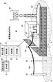
- FIGS. 1 and 2 differ in the laying mode of a part of the optical fiber 10Y, but the other configurations are the same.
- the mobile base station 40 is mainly composed of a station building 41, an antenna tower 44, and the like. Further, the station building 41 is provided with, for example, a wireless device 42, a power supply facility 43, and the like. Further, although the mobile base station 40 is completely surrounded by the fence F, the fence F on the back side and the right side is not shown in FIGS. 1 and 2 for the sake of simplification of the drawings.
- the act of destroying equipment is an act of destroying the radio device 42, the power supply equipment 43, the antenna tower 44, the fence F, and the like.
- the equipment theft is an act of stealing the wireless device 42 itself, the power supply equipment 43 itself, or the like, or an act of stealing the wireless device 42, the power supply equipment 43, the parts of the antenna tower 44, or the like.
- the parts of the antenna tower 44 are bolts of the antenna tower 44 and the like.
- the detection system detects threats such as the above-mentioned vandalism and theft in the mobile base station area 45, and includes optical fibers 10X and 10Y, a transmitter / receiver 20, and a detection device 30. I have.
- the detection device 30 includes an acquisition unit 31 and a detection unit 32.
- the detection device 30 can be arranged at a position away from the transmission / reception unit 20, and can be arranged on the cloud, for example.
- the optical fiber 10X is laid on a plurality of utility poles 50 (three utility poles 50 in the examples of FIGS. 1 and 2), one end of which is connected to the transmission / reception unit 20 and the other end of which is connected to an exchange.
- the optical fiber 10X may be buried in the underground G.
- the optical fiber 10Y is laid so as to route the wireless device 42, the power supply equipment 43, and the antenna tower 44, and one end thereof is connected to the transmission / reception unit 20. Further, a part of the optical fiber 10Y is laid in the fence F in the example of FIG. 1, and is buried in the underground G along the fence F in the example of FIG.
- the method of laying the optical fibers 10X and 10Y is not limited to that shown in FIG. If at least one of the optical fibers 10X and 10Y is laid in the mobile base station area 45, the optical fibers 10X and 10Y can be laid by any method.
- the optical fiber 10 may be an optical fiber dedicated to sensing, or an optical fiber for both communication and sensing.
- the optical signal for sensing is demultiplexed by a filter (not shown) in front of the transmission / reception unit 20, and only the optical signal for sensing is received by the transmission / reception unit 20. It can be so.
- the transmission / reception unit 20 is provided inside the wireless device 42, and receives an optical signal (optical signal for sensing; hereinafter the same) from the optical fiber 10X.
- the transmission / reception unit 20 is an example of a reception unit.
- the transmission / reception unit 20 receives pulsed light incident on the optical fiber 10X, and receives backscattered light generated as the pulsed light is transmitted through the optical fiber 10X as an optical signal. Further, the transmission / reception unit 20 receives an optical signal from the optical fiber 10Y in the same manner as the optical fiber 10X.
- the installation destination of the transmission / reception unit 20 is not limited to the inside of the wireless device 42.
- the transmission / reception unit 20 may be on the concentrating station side of the optical fiber 10X or the optical fiber 10Y.
- the transmission / reception unit 20 is arranged on the exchange side, even if a power failure occurs in the power supply equipment 43, it is possible to detect an event occurring in the mobile base station area 45 as long as the optical fiber 10 is not disconnected. Is.
- the optical fiber 10 can detect a state such as whether or not a vandalism or theft has occurred in the mobile base station area 45. Further, the optical signal received by the transmission / reception unit 20 includes information indicating the state of the mobile base station area 45 detected by the optical fiber 10.
- the acquisition unit 31 acquires information indicating the state of the mobile base station area 45 included in the optical signal received by the transmission / reception unit 20.
- the detection unit 32 detects threats such as the above-mentioned vandalism and theft in the mobile base station area 45 based on the information acquired by the acquisition unit 31 indicating the state of the mobile base station area 45.
- the information indicating the state of the mobile base station area 45 detected by the optical fiber 10 includes the action that has occurred.
- the vibration pattern of the vibration generated and the acoustic pattern of the sound are included. These vibration patterns and acoustic patterns are dynamically fluctuating fluctuation patterns, and are peculiar fluctuation patterns according to the type of action that has occurred.
- the vibration pattern is a fluctuation pattern in which the strength of vibration, the vibration position, the fluctuation transition of the frequency, and the like differ depending on the type of action that has occurred.
- the detection unit 32 detects the above-mentioned actions (1) to (3) by the method shown below. In the following, as an example, an example of detecting the above-mentioned actions (1) to (3) using a vibration pattern will be described.
- the detection unit 32 does not show the vibration pattern of the vibration actually generated when the action occurs in the mobile base station area 45 for each of the actions (1) to (3) described above as a matching pattern. Store it in a memory or the like in advance. For example, when the above-mentioned action (1) occurs, it is considered that the vibration pattern of the vibration generated when a large impact is applied appears. Further, when the above-mentioned action (2) occurs, it is considered that the vibration pattern of the vibration generated when the equipment is dragged appears. Further, when the above-mentioned action (3) occurs, it is considered that the vibration pattern of the vibration generated when the equipment is disassembled appears.
- the acquisition unit 31 acquires information indicating the state of the mobile base station area 45 included in the optical signal received by the transmission / reception unit 20. Subsequently, the detection unit 32 compares the vibration pattern included in the information acquired by the acquisition unit 31 with the matching pattern. When there is a matching pattern in the matching pattern whose matching rate with the vibration pattern is equal to or higher than the threshold value, the detection unit 32 indicates that an act corresponding to the matching pattern has occurred in the mobile base station area 45. to decide.
- the detection unit 32 specifies the position (distance of the optical fiber 10 from the transmission / reception unit 20) where the optical signal including the information indicating the state of the mobile base station area 45 is generated, as follows. It is possible.
- the detection unit 32 is located at a position where the optical signal is generated (transmission / reception) based on the time difference between the time when the transmission / reception unit 20 incidents the pulsed light on the optical fiber 10Y and the time when the optical signal is received from the optical fiber 10Y. It is possible to specify the distance of the optical fiber 10Y from the unit 20). Alternatively, the detection unit 32 can specify the position where the optical signal is generated based on the reception intensity of the optical signal received by the transmission / reception unit 20. For example, the detection unit 32 specifies that the position where the optical signal is generated is farther from the transmission / reception unit 20 as the reception intensity of the optical signal is smaller.
- the identification of the generation position of the optical signal is not limited to that performed by the detection unit 32.
- the transmission / reception unit 20 may specify the optical signal generation position, and the acquisition unit 31 may acquire information on the optical signal generation position from the transmission / reception unit 20.
- the detection unit 32 provides a corresponding table in which the distance of the optical fiber 10 from the transmission / reception unit 20 and the laying destination where the optical fiber 10 is laid at that distance are associated with each optical fiber 10X and 10Y. Keep it.
- FIG. 3 shows an example of a corresponding table for the optical fiber 10Y.
- the detection unit 32 detects the above-mentioned action (1) based on the information indicating the state of the mobile base station area 45 included in the optical signal received from the optical fiber 10Y by the transmission / reception unit 20. It is assumed that the position where the optical signal is generated (distance of the optical fiber 10Y from the transmission / reception unit 20) is within the range of a5 to a6 [m]. In this case, the detection unit 32 can determine that the above-mentioned act (1) with respect to the antenna tower 44, that is, the act of destroying the antenna tower 44 has occurred by referring to the corresponding table shown in FIG. can.
- the detection unit 32 has, for each of the above-mentioned actions (1) to (3), the teacher data indicating the action, and the vibration pattern of the vibration actually generated when the action occurs in the mobile base station area 45. , are prepared, each prepared set is input, a learning model by a convolutional neural network (CNN) is constructed in advance, and the learning model is stored in advance in a memory (not shown) or the like.
- CNN convolutional neural network
- the acquisition unit 31 acquires information indicating the state of the mobile base station area 45 included in the optical signal received by the transmission / reception unit 20. Subsequently, the detection unit 32 inputs the vibration pattern included in the information acquired by the acquisition unit 31 into the learning model. As a result, when any of the above-mentioned actions (1) to (3) occurs in the mobile base station area 45, the detection unit 32 outputs the learning model in the mobile base station area 45. Get the action that occurred.
- the detection unit 32 may hold a correspondence table as shown in FIG. 3 in the same manner as the method A described above. As a result, the detection unit 32 can determine in which equipment in the mobile base station area 45 the above-mentioned actions (1) to (3) have occurred, as in the case of the above-mentioned method A. can.
- the transmission / reception unit 20 receives an optical signal from the optical fiber 10 including information indicating the state of the mobile base station area 45 (step S11).
- the acquisition unit 31 acquires information indicating the state of the mobile base station area 45 included in the optical signal received by the transmission / reception unit 20, and the detection unit 32 obtains information indicating the state of the mobile base station area 45. Based on this, a threat within the mobile base station area 45 (for example, the actions (1) to (3) described above) is detected (step S12). At this time, for example, the detection unit 32 may detect the threat in the mobile base station area 45 by using any of the above-mentioned methods A and B.
- the transmission / reception unit 20 receives an optical signal from the optical fiber 10 including information indicating the state of the mobile base station area 45.
- the detection unit 32 detects a threat in the mobile base station area 45 based on the information including the optical signal indicating the state of the mobile base station area 45. As a result, the threat can be detected within the range in which the optical fiber 10 in the mobile base station area 45 is laid, so that the threat in the mobile base station area 45 can be comprehensively detected.
- FIG. 5 is a modified example of FIG. 1, but the present invention is not limited to this, and FIG. 2 may be modified.
- the reporting destination terminal 60 is added and the inside of the detection device 30 is compared with the configuration of the first embodiment described above. It differs from the point that the notification unit 33 is added.
- the reporting destination terminal 60 is a terminal installed at the reporting destination when a threat occurs in the mobile base station area 45.
- the report destination is, for example, fire department, police, etc.
- the reporting destination terminal 60 includes a display unit 61 which is a display, a monitor, or the like for displaying various information.
- the notification unit 33 When the detection unit 32 determines that a threat has occurred in the mobile base station area 45, the notification unit 33 notifies the report destination terminal 60 that a threat has occurred in the mobile base station area 45 by telephone, e-mail, or the like. report.
- the notification unit 33 may store in advance the information indicating the position of the mobile base station area 45 and the map information in association with each other. Then, when the detection unit 32 determines that a threat has occurred in the mobile base station area 45, the notification unit 33 notifies the GUI (Graphical User Interface) screen in which the position of the mobile base station area 45 is superimposed on the map. It may be displayed on the display unit 61 of the destination terminal 60. An example of this GUI screen is shown in FIG. In the example of FIG. 6, the position of the mobile base station area 45 where the threat has occurred is highlighted by a circle including the position on the map.
- GUI Graphic User Interface
- the notification unit 33 may generate a warning sound in the vicinity of the equipment, track the vicinity of the equipment with a surveillance camera, and the like.
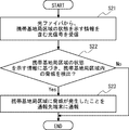
- the transmission / reception unit 20 receives an optical signal from the optical fiber 10 including information indicating the state of the mobile base station area 45 (step S21).
- the acquisition unit 31 acquires information indicating the state of the mobile base station area 45 included in the optical signal received by the transmission / reception unit 20, and the detection unit 32 obtains information indicating the state of the mobile base station area 45. Based on this, a threat within the mobile base station area 45 (for example, the actions (1) to (3) described above) is detected (step S22).
- step S22 when the detection unit 32 determines that a threat has occurred in the mobile base station area 45 (Yes in step S22), the notification unit 33 subsequently determines that a threat has occurred in the mobile base station area 45. Is reported to the reporting destination terminal 60 by telephone, e-mail, or the like (step S23). At this time, the notification unit 33 may display the GUI screen on which the position of the mobile base station area 45 is superimposed on the map on the display unit 61 of the notification destination terminal 60.
- the notification unit 33 when the detection unit 32 determines that a threat has occurred in the mobile base station area 45, the notification unit 33 has generated a threat in the mobile base station area 45. Is reported to the reporting destination terminal 60. As a result, it is possible to notify the report destinations such as the fire department and the police that a threat has occurred in the mobile base station area 45.
- the notification unit 33 may display the GUI screen on which the position of the mobile base station area 45 is superimposed on the map on the display unit 61 of the notification destination terminal 60.
- the location of the mobile base station area 45 where the threat has occurred can also be notified to the report destinations such as the fire department and the police.
- Other effects are the same as those in the first embodiment described above.
- This modification is an example assuming that a plurality of mobile base station areas 45 exist in the above-described second embodiment.
- a plurality of detection devices 30 are provided corresponding to each of the plurality of mobile base station areas 45. Then, each of the plurality of detection devices 30 detects the threat in the corresponding mobile base station area 45.
- the detection devices 30A and 30B corresponding to each of the mobile base station areas 45A and 45B are provided. That is, in the example of FIG. 8, three detection devices 30, 30A, and 30B are provided.
- one notification unit 33 is provided for the three detection devices 30, 30A and 30B.
- the notification unit 33 determines that any of the detection devices 30, 30A, 30B has caused a threat inside any of the mobile base station areas 45, 45A, 45B, the notification unit 33 determines that a threat has occurred inside the mobile base station areas 45, 45A, 45B. Notify the reporting destination terminal 60 that a threat has occurred inside any of the above.
- the notification unit 33 may store in advance the information indicating the positions of the mobile base station areas 45, 45A and 45B and the map information in association with each other. Then, when the notification unit 33 determines that any of the detection devices 30, 30A, 30B has caused a threat inside any of the mobile base station areas 45, 45A, 45B, the notification unit 33 determines that a threat has occurred inside the mobile base station areas 45, 45A. , 45B, the GUI screen in which the position of the mobile base station area where the threat occurred is superimposed on the map may be displayed on the display unit 61 of the reporting destination terminal 60. An example of this GUI screen is shown in FIG. In the example of FIG. 9, the positions of the three mobile base station areas 45, 45A, and 45B are shown on the map, and the position of the mobile base station area where the threat occurred is highlighted by a circle including the position. It is represented as.
- the transmission / reception unit 20 and the detection device 30 are separated, but the present invention is not limited to this.
- the transmission / reception unit 20 and the detection device 30 may be integrated, and the transmission / reception unit 20 may be provided inside the detection device 30.
- FIG. 10 shows a configuration example of the detection device 30 having the transmission / reception unit 20 inside.
- the detection device 30 shown in FIG. 10 may be provided inside the wireless device 42 instead of the transmission / reception unit 20 in the detection system shown in FIGS. 1, 2, 5, and 8.
- the detection unit 32 detects the above-mentioned actions (1) to (3) as a threat within the mobile base station area 45, but the present invention is not limited to this.
- the detection unit 32 may detect an act of intruding into the mobile base station area 45, a suspicious act in the mobile base station area 45, an act of stealing the optical fibers 10X and 10Y, and the like.
- the detection unit 32 adds a vibration pattern when an intrusion or suspicious act occurs as a matching pattern. You should keep it.
- the detection unit 32 may additionally learn the vibration pattern when an intrusion act or a suspicious act occurs in the learning model.
- the detection unit 32 may be affected by the fact that the optical signal from the optical fiber 10X is blocked, the optical signal having a large vibration intensity is detected by the optical fiber 10X, and the like. , It may be determined that the optical fiber 10X has been stolen. Further, the detection unit 32 may determine in the same manner when the optical fiber 10Y is stolen.
- one transmission / reception unit 20 and one detection device 30 are provided for each of the plurality of optical fibers 10X and 10Y, but the present invention is not limited to this.
- a plurality of transmission / reception units 20 and a plurality of detection devices 30 may be provided corresponding to the plurality of optical fibers 10X and 10Y, respectively.
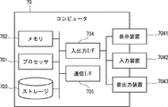
- the computer 70 includes a processor 701, a memory 702, a storage 703, an input / output interface (input / output I / F) 704, a communication interface (communication I / F) 705, and the like.
- the processor 701, the memory 702, the storage 703, the input / output interface 704, and the communication interface 705 are connected by a data transmission line for transmitting and receiving data to and from each other.
- the processor 701 is, for example, an arithmetic processing unit such as a CPU (Central Processing Unit) or a GPU (Graphics Processing Unit).
- the memory 702 is, for example, a memory such as a RAM (RandomAccessMemory) or a ROM (ReadOnlyMemory).
- the storage 703 is a storage device such as an HDD (Hard Disk Drive), an SSD (Solid State Drive), or a memory card. Further, the storage 703 may be a memory such as a RAM or a ROM.
- the storage 703 stores a program that realizes the functions of the components included in the detection device 30. By executing each of these programs, the processor 701 realizes the functions of the components included in the detection device 30. Here, when executing each of the above programs, the processor 701 may read these programs onto the memory 702 and then execute the programs, or may execute the programs without reading them onto the memory 702. The memory 702 and the storage 703 also play a role of storing information and data held by the components included in the detection device 30.
- Non-temporary computer-readable media include various types of tangible storage media.
- Examples of non-temporary computer-readable media include magnetic recording media (eg, flexible disks, magnetic tapes, hard disk drives), opto-magnetic recording media (eg, opto-magnetic disks), CD-ROMs (Compact Disc-ROMs), CDs. -R (CD-Recordable), CD-R / W (CD-ReWritable), semiconductor memory (for example, mask ROM, PROM (Programmable ROM), EPROM (Erasable PROM), flash ROM, RAM.
- the program also includes.
- the computer-readable medium can supply the program to the computer via a wired communication path such as an electric wire and an optical fiber, or a wireless communication path.
- the input / output interface 704 is connected to the display device 7041, the input device 7042, the sound output device 7043, and the like.
- the display device 7041 is a device that displays a screen corresponding to drawing data processed by the processor 701, such as an LCD (Liquid Crystal Display), a CRT (Cathode Ray Tube) display, and a monitor.
- the input device 7042 is a device that receives an operator's operation input, and is, for example, a keyboard, a mouse, a touch sensor, and the like.
- the display device 7041 and the input device 7042 may be integrated and realized as a touch panel.
- the sound output device 7043 is a device such as a speaker that acoustically outputs sound corresponding to acoustic data processed by the processor 701.
- the communication interface 705 transmits / receives data to / from an external device.
- the communication interface 705 communicates with an external device via a wired communication path or a wireless communication path.
- Appendix 1 Optical fiber laid in the mobile base station area where the mobile base station is installed, A receiving unit that receives an optical signal including information indicating the state of the mobile base station area from the optical fiber. A detection unit that detects a threat in the mobile base station area based on information indicating the state of the mobile base station area included in the optical signal, and a detection unit. A detection system. (Appendix 2) The detection unit detects the vandalism of the equipment of the mobile base station as a threat in the mobile base station area. The detection system according to Appendix 1.
- the detection unit detects the theft of the equipment of the mobile base station as a threat in the mobile base station area.
- the detection system according to Appendix 1.
- (Appendix 4) Report destination terminal and When the detection unit determines that a threat has occurred in the mobile base station area, it further includes a notification unit that notifies the reporting destination terminal that a threat has occurred in the mobile base station area.
- the detection system according to any one of Appendix 1 to 3.
- the reporting destination terminal includes a display unit and includes a display unit. When the detection unit determines that a threat has occurred in the mobile base station area, the notification unit superimposes the position of the mobile base station area where the threat has occurred on the map and displays it on the display unit.
- the detection system according to Appendix 4.
- An acquisition unit that acquires information indicating the state of the mobile base station area included in an optical signal received from an optical fiber laid in the mobile base station area where the mobile base station is installed, and an acquisition unit.
- a detection unit that detects a threat in the mobile base station area based on information indicating the state of the mobile base station area, and a detection unit.
- a detection device. (Appendix 7) The detection unit detects the vandalism of the equipment of the mobile base station as a threat in the mobile base station area.
- the detection device according to Appendix 6. (Appendix 8) The detection unit detects the theft of the equipment of the mobile base station as a threat in the mobile base station area.
- the detection device according to Appendix 6.
- Detection methods including. (Appendix 12) In the detection step, as a threat within the mobile base station area, a vandalism to the equipment of the mobile base station is detected. The detection method according to Appendix 11. (Appendix 13) In the detection step, theft of the equipment of the mobile base station is detected as a threat in the mobile base station area. The detection method according to Appendix 11.
Landscapes
- Physics & Mathematics (AREA)
- General Physics & Mathematics (AREA)
- Life Sciences & Earth Sciences (AREA)
- General Life Sciences & Earth Sciences (AREA)
- Geophysics (AREA)
- Alarm Systems (AREA)
- Mobile Radio Communication Systems (AREA)
Priority Applications (3)
| Application Number | Priority Date | Filing Date | Title |
|---|---|---|---|
| US17/798,387 US20230070029A1 (en) | 2020-02-28 | 2020-02-28 | Detection system, detection device, and detection method |
| PCT/JP2020/008456 WO2021171593A1 (ja) | 2020-02-28 | 2020-02-28 | 検出システム、検出装置、及び検出方法 |
| JP2022503032A JPWO2021171593A1 (https=) | 2020-02-28 | 2020-02-28 |
Applications Claiming Priority (1)
| Application Number | Priority Date | Filing Date | Title |
|---|---|---|---|
| PCT/JP2020/008456 WO2021171593A1 (ja) | 2020-02-28 | 2020-02-28 | 検出システム、検出装置、及び検出方法 |
Publications (1)
| Publication Number | Publication Date |
|---|---|
| WO2021171593A1 true WO2021171593A1 (ja) | 2021-09-02 |
Family
ID=77492091
Family Applications (1)
| Application Number | Title | Priority Date | Filing Date |
|---|---|---|---|
| PCT/JP2020/008456 Ceased WO2021171593A1 (ja) | 2020-02-28 | 2020-02-28 | 検出システム、検出装置、及び検出方法 |
Country Status (3)
| Country | Link |
|---|---|
| US (1) | US20230070029A1 (https=) |
| JP (1) | JPWO2021171593A1 (https=) |
| WO (1) | WO2021171593A1 (https=) |
Cited By (1)
| Publication number | Priority date | Publication date | Assignee | Title |
|---|---|---|---|---|
| WO2023089692A1 (ja) * | 2021-11-17 | 2023-05-25 | 日本電気株式会社 | 異常判定方法、異常判定装置、異常判定システム及び非一時的なコンピュータ可読媒体 |
Citations (3)
| Publication number | Priority date | Publication date | Assignee | Title |
|---|---|---|---|---|
| JP2006279854A (ja) * | 2005-03-30 | 2006-10-12 | Kyocera Corp | 機器装置の盗難防止システム、無線通信基地局装置、及び機器装置の盗難防止方法 |
| CN107861134A (zh) * | 2017-11-09 | 2018-03-30 | 南京派光信息技术有限公司 | 基于北斗、分布式光纤和雷达探测的铁塔实时监测系统 |
| CN208569808U (zh) * | 2018-11-05 | 2019-03-01 | 宝鸡中盛银行安全专业有限公司 | 一种通讯基站防盗系统 |
Family Cites Families (9)
| Publication number | Priority date | Publication date | Assignee | Title |
|---|---|---|---|---|
| JP2001134851A (ja) * | 1999-11-02 | 2001-05-18 | Home Aiai To Keibi Kiki:Kk | 光ファイバケーブルを利用した侵入監視センサ |
| US7488929B2 (en) * | 2003-08-13 | 2009-02-10 | Zygo Corporation | Perimeter detection using fiber optic sensors |
| JP2005345137A (ja) * | 2004-05-31 | 2005-12-15 | Fujikura Ltd | 侵入者検知装置 |
| JP2006209575A (ja) * | 2005-01-31 | 2006-08-10 | Mitsubishi Heavy Ind Ltd | 侵入者検知機能付きフェンス |
| JP2009128984A (ja) * | 2007-11-20 | 2009-06-11 | Yamamoto Sangyo Kk | 敷物および監視装置 |
| CN201327671Y (zh) * | 2008-12-11 | 2009-10-14 | 中国移动通信集团甘肃有限公司 | 一种基站防盗系统 |
| FR2964232B1 (fr) * | 2010-09-01 | 2013-06-28 | Commissariat Energie Atomique | Systeme de detection d'intrusion et procede de montage d'un tel systeme |
| JP5771955B2 (ja) * | 2010-11-16 | 2015-09-02 | 住友電気工業株式会社 | 対象識別装置及び対象識別方法 |
| CN203799460U (zh) * | 2014-02-08 | 2014-08-27 | 上海波汇通信科技有限公司 | 基于光纤传感的隧道电缆入侵探测系统 |
-
2020
- 2020-02-28 US US17/798,387 patent/US20230070029A1/en not_active Abandoned
- 2020-02-28 WO PCT/JP2020/008456 patent/WO2021171593A1/ja not_active Ceased
- 2020-02-28 JP JP2022503032A patent/JPWO2021171593A1/ja active Pending
Patent Citations (3)
| Publication number | Priority date | Publication date | Assignee | Title |
|---|---|---|---|---|
| JP2006279854A (ja) * | 2005-03-30 | 2006-10-12 | Kyocera Corp | 機器装置の盗難防止システム、無線通信基地局装置、及び機器装置の盗難防止方法 |
| CN107861134A (zh) * | 2017-11-09 | 2018-03-30 | 南京派光信息技术有限公司 | 基于北斗、分布式光纤和雷达探测的铁塔实时监测系统 |
| CN208569808U (zh) * | 2018-11-05 | 2019-03-01 | 宝鸡中盛银行安全专业有限公司 | 一种通讯基站防盗系统 |
Cited By (4)
| Publication number | Priority date | Publication date | Assignee | Title |
|---|---|---|---|---|
| WO2023089692A1 (ja) * | 2021-11-17 | 2023-05-25 | 日本電気株式会社 | 異常判定方法、異常判定装置、異常判定システム及び非一時的なコンピュータ可読媒体 |
| JPWO2023089692A1 (https=) * | 2021-11-17 | 2023-05-25 | ||
| JP7647923B2 (ja) | 2021-11-17 | 2025-03-18 | 日本電気株式会社 | 異常判定方法、異常判定装置、異常判定システム及び異常判定プログラム |
| US12573275B2 (en) * | 2021-11-17 | 2026-03-10 | Nec Corporation | Abnormality determination method, abnormality determination apparatus, abnormality determination system, and non-transitory computer-readable medium |
Also Published As
| Publication number | Publication date |
|---|---|
| JPWO2021171593A1 (https=) | 2021-09-02 |
| US20230070029A1 (en) | 2023-03-09 |
Similar Documents
| Publication | Publication Date | Title |
|---|---|---|
| JP7315014B2 (ja) | 光ファイバセンシングシステム、光ファイバセンシング方法、及び光ファイバセンシング装置 | |
| WO2020116030A1 (ja) | 道路監視システム、道路監視装置、道路監視方法、及び非一時的なコンピュータ可読媒体 | |
| US20100156637A1 (en) | Method for detecting an intruder's path | |
| JP2024014948A (ja) | 道路監視システム、道路監視装置、道路監視方法、及びプログラム | |
| JP2023538474A (ja) | ケーブル切断防止のための統計的画像処理に基づく異常検出 | |
| JP7318706B2 (ja) | 光ファイバセンシングシステム及び音源位置特定方法 | |
| US9778227B2 (en) | Device and system for and a method of monitoring a cable for a physical disturbance | |
| US20150195693A1 (en) | Earthquake early warning system utilizing a multitude of smart phones | |
| CN208903386U (zh) | 入侵报警设备及系统 | |
| JP7276356B2 (ja) | 光ファイバセンシングシステム、状態検知装置、状態検知方法、及びプログラム | |
| JP7235115B2 (ja) | 光ファイバセンシングシステム、光ファイバセンシング機器、及び異常判断方法 | |
| KR20110031923A (ko) | 해일 경보 시스템과 해일 경보를 제공하는 방법 | |
| WO2020166057A1 (ja) | 光ファイバセンシングシステム、行動特定装置、行動特定方法、及びコンピュータ可読媒体 | |
| US20230401941A1 (en) | Monitoring system, monitoring apparatus, monitoring method, and computer readable medium | |
| JP7533566B2 (ja) | 監視システム、監視装置、及び監視方法 | |
| Wang et al. | Employing fiber sensing and on-premise AI solutions for cable safety protection over telecom infrastructure | |
| Vikram et al. | Detecting accurate parametric intrusions using optical fiber sensors for long-distance data communication system | |
| WO2021171593A1 (ja) | 検出システム、検出装置、及び検出方法 | |
| JP7315011B2 (ja) | 光ファイバセンシングシステム、監視方法、及びプログラム | |
| JP7192879B2 (ja) | 線路監視システム、線路監視装置、線路監視方法、及びプログラム | |
| WO2021005649A1 (ja) | 光ファイバセンシングシステム、光ファイバセンシング機器、及び地中行動監視方法 | |
| CN113593190A (zh) | 一种消防水电专用抗震支架及检测疏散报警系统 | |
| GB2418763A (en) | System and method for securing a large infrastructure | |
| US20230417593A1 (en) | Optical fiber sensing system, optical fiber sensing method, and optical fiber sensing device | |
| KR101416076B1 (ko) | 감시카메라 비상호출 시스템 |
Legal Events
| Date | Code | Title | Description |
|---|---|---|---|
| 121 | Ep: the epo has been informed by wipo that ep was designated in this application |
Ref document number: 20921994 Country of ref document: EP Kind code of ref document: A1 |
|
| ENP | Entry into the national phase |
Ref document number: 2022503032 Country of ref document: JP Kind code of ref document: A |
|
| NENP | Non-entry into the national phase |
Ref country code: DE |
|
| 122 | Ep: pct application non-entry in european phase |
Ref document number: 20921994 Country of ref document: EP Kind code of ref document: A1 |