WO2021167103A1 - 取付構造及び取付方法 - Google Patents
取付構造及び取付方法 Download PDFInfo
- Publication number
- WO2021167103A1 WO2021167103A1 PCT/JP2021/006517 JP2021006517W WO2021167103A1 WO 2021167103 A1 WO2021167103 A1 WO 2021167103A1 JP 2021006517 W JP2021006517 W JP 2021006517W WO 2021167103 A1 WO2021167103 A1 WO 2021167103A1
- Authority
- WO
- WIPO (PCT)
- Prior art keywords
- end wall
- wall engaging
- metal fitting
- plate portion
- engaging member
- Prior art date
- Legal status (The legal status is an assumption and is not a legal conclusion. Google has not performed a legal analysis and makes no representation as to the accuracy of the status listed.)
- Ceased
Links
Images


Classifications
-
- E—FIXED CONSTRUCTIONS
- E04—BUILDING
- E04F—FINISHING WORK ON BUILDINGS, e.g. STAIRS, FLOORS
- E04F11/00—Stairways, ramps, or like structures; Balustrades; Handrails
- E04F11/18—Balustrades; Handrails
-
- H—ELECTRICITY
- H02—GENERATION; CONVERSION OR DISTRIBUTION OF ELECTRIC POWER
- H02S—GENERATION OF ELECTRIC POWER BY CONVERSION OF INFRARED RADIATION, VISIBLE LIGHT OR ULTRAVIOLET LIGHT, e.g. USING PHOTOVOLTAIC [PV] MODULES
- H02S20/00—Supporting structures for PV modules
- H02S20/20—Supporting structures directly fixed to an immovable object
- H02S20/22—Supporting structures directly fixed to an immovable object specially adapted for buildings
-
- Y—GENERAL TAGGING OF NEW TECHNOLOGICAL DEVELOPMENTS; GENERAL TAGGING OF CROSS-SECTIONAL TECHNOLOGIES SPANNING OVER SEVERAL SECTIONS OF THE IPC; TECHNICAL SUBJECTS COVERED BY FORMER USPC CROSS-REFERENCE ART COLLECTIONS [XRACs] AND DIGESTS
- Y02—TECHNOLOGIES OR APPLICATIONS FOR MITIGATION OR ADAPTATION AGAINST CLIMATE CHANGE
- Y02B—CLIMATE CHANGE MITIGATION TECHNOLOGIES RELATED TO BUILDINGS, e.g. HOUSING, HOUSE APPLIANCES OR RELATED END-USER APPLICATIONS
- Y02B10/00—Integration of renewable energy sources in buildings
- Y02B10/10—Photovoltaic [PV]
-
- Y—GENERAL TAGGING OF NEW TECHNOLOGICAL DEVELOPMENTS; GENERAL TAGGING OF CROSS-SECTIONAL TECHNOLOGIES SPANNING OVER SEVERAL SECTIONS OF THE IPC; TECHNICAL SUBJECTS COVERED BY FORMER USPC CROSS-REFERENCE ART COLLECTIONS [XRACs] AND DIGESTS
- Y02—TECHNOLOGIES OR APPLICATIONS FOR MITIGATION OR ADAPTATION AGAINST CLIMATE CHANGE
- Y02E—REDUCTION OF GREENHOUSE GAS [GHG] EMISSIONS, RELATED TO ENERGY GENERATION, TRANSMISSION OR DISTRIBUTION
- Y02E10/00—Energy generation through renewable energy sources
- Y02E10/50—Photovoltaic [PV] energy
Definitions
- the present invention relates to a mounting structure and a mounting method.
- a method is known in which a mounting structure is provided on the roof and the solar panel is fixed using the mounting structure. Further, in the case of an apartment house such as an apartment, a method is known in which a mounting structure is provided not on the roof but on the waist wall of the veranda and the solar panel is fixed using the mounting structure (for example, Patent Document 1).
- the present invention is intended to provide a mounting structure in which the mounting work is simple and the mounting structure is hard to come off from the wall.
- the present invention has a mounting structure that can be mounted on the mounted member, and the upper end wall engaging member that engages with the upper end portion of the mounted member and the lower end wall that engages with the lower end portion of the mounted member. It is characterized by including an engaging member, a connecting mechanism for connecting the upper end wall engaging member and the lower end wall engaging member.
- the present invention is a mounting method for mounting a mounting structure to a mounted member, in which an upper end wall engaging member that engages with the upper end of the mounted member and a lower end that engages with the lower end of the mounted member.
- An engagement step that is performed after the separation step to engage the upper end wall engaging member and the lower end wall engaging member with the mounted member, and a step that is performed after the engaging step and is performed on the mounted member.
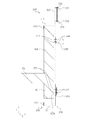
- FIG. 1 It is a perspective view which shows the outline of the 1st mounting structure. It is an end view which shows the outline of the 1st mounting structure.
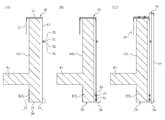
- (A) to (C) are end view views showing the outline of the first mounting structure, respectively.
- an arbitrary direction in the horizontal plane is referred to as the X direction
- a direction orthogonal to the X direction in the horizontal plane is referred to as the Y direction
- a vertical direction is referred to as the Z direction.
- the mounting structure 2 is mounted on the veranda B (attached member).
- the veranda B includes a floor member B1 provided in the horizontal direction and a wall member B2 connected to the floor member B1.
- the wall member B2 is provided in the direction perpendicular to the floor member B1.
- the wall member B2 includes an upper wall portion B2U projecting from the upper surface of the floor member B1 and a lower wall portion B2L projecting from the lower surface of the floor member B1.
- the upper wall portion B2U includes a waist wall portion B2U1 and a handrail plate B2U2 provided at the upper end portion of the waist wall portion B2U1.
- the mounting structure 2 includes an upper end wall engaging metal fitting 10 (upper end wall engaging member) that engages with the upper wall portion B2U and a lower end wall engaging metal fitting 20 (lower end wall engaging member) that engages with the lower wall portion B2L. , Connected to the connecting mechanism 30 that connects the upper end wall engaging metal fitting 10 and the lower end wall engaging metal fitting 20, and the upper end wall engaging metal fitting 10, and holds the solar panel SP (held member) with respect to the upper end portion.
- the panel upper end holding metal fitting 40 (upper end holding structure) and the panel lower end holding metal fitting 50 (upper end holding structure) which are connected to the lower end wall engaging metal fitting 20 and hold the lower end of the solar panel SP. Be prepared.
- the upper end wall engaging metal fitting 10 is arranged along the inner (left side in FIG. 2) side surface of the upper wall portion B2U connected to the upper surface plate portion 11 and the upper surface plate portion 11 arranged on the upper end surface of the upper wall portion B2U.
- the upper end inner side surface plate portion 12 is provided, and the upper end outer surface plate portion 13 which is connected to the upper surface plate portion 11 and is arranged along the outer side surface (right side in FIG. 2) of the upper wall portion B2U.
- the top plate portion 11 is arranged horizontally.
- the upper end inner side surface plate portion 12 and the upper end outer surface plate portion 13 are arranged vertically, respectively.
- the lower end of the upper end inner side plate portion 12 is separated from the floor member B1.
- the lower end of the upper end inner side plate portion 12 may be close to the floor member B1.
- the lower end wall engaging metal fitting 20 is connected to the lower surface plate portion 21 arranged along the lower end surface of the lower wall portion B2L and along the inner side surface (left side in FIG. 2) of the lower wall portion B2L.
- the lower end inner side surface plate portion 22 is provided, and the lower end outer surface plate portion 23 which is connected to the lower surface plate portion 21 and is arranged along the outer side surface (right side in FIG. 2) of the lower wall portion B2L.
- the bottom plate portion 21 is arranged horizontally.
- the lower end inner side surface plate portion 22 and the lower end outer surface plate portion 23 are arranged vertically, respectively.
- the upper end portion of the lower end inner side plate portion 22 is separated from the floor member B1.
- the upper end of the lower end inner side plate portion 22 may be close to the floor member B1.
- the connecting mechanism 30 includes an upper bent portion 231 provided at the lower end portion of the upper end outer face plate portion 13 and having an upper bolt hole, and a lower bent portion provided at the upper end portion of the lower end outer face plate portion 23 and having a lower bolt hole.
- 32 a bolt 33 capable of communicating the upper bolt hole and the lower bolt hole, and a nut 34 screwed into the bolt 33 are provided.
- the upper bent portion 231 is connected to the lower end portion of the upper end outer face plate portion 13 and extends in the XY plane.
- the lower bent portion 32 is connected to the upper end portion of the lower end outer face plate portion 23 and extends in the XY plane.
- the bolt 33 is preferably inserted through the bolt hole on the upper bent portion 231 side.
- the nut 34 is preferably arranged on the lower side of the lower bent portion 32.
- the panel upper end holding metal fitting 40 includes an upper surface holding plate portion 41 arranged along the upper surface of the upper surface plate portion 11 and an upper inner vertical portion 42 extending upward in the Z direction from the outer end portion in the Y direction of the upper surface holding plate portion 41.
- An upper horizontal portion 43 extending outward in the Y direction from the upper end portion of the upper inner vertical portion 42 in the Z direction, and an upper outer vertical portion 44 extending downward in the Z direction from the outer end portion of the upper horizontal portion 43 in the Y direction are provided.
- the upper surface holding plate portion 41 and the upper horizontal portion 43 are arranged horizontally.
- the upper inner vertical portion 42 and the upper outer vertical portion 44 are arranged vertically.
- a gap may be formed between the upper inner vertical portion 42 and the upper outer vertical portion 44 so that the upper end portion of the solar panel SP can be inserted.
- Bolt holes are formed in the upper surface plate portion 11 and the upper surface holding plate portion 41, respectively.
- the panel upper end holding metal fitting 40 further includes a bolt 47 that can be inserted into both bolt holes and a nut 48 that is screwed into the bolt 47.
- the bolt 47 is preferably inserted through the bolt hole on the upper surface holding plate portion 41 side.
- the nut 48 is preferably arranged on the wall member B2 side of the top plate portion 11.
- the panel lower end holding bracket 50 includes a lower inner vertical portion 51 arranged along the lower end outer face plate portion 23, a lower horizontal portion 52 extending outward in the Y direction from the lower inner vertical portion 51 in the Z direction, and a lower horizontal portion.
- An upper and outer vertical portion 53 extending upward in the Z direction from the outer end portion in the Y direction of the portion 52 is provided.
- the lower inner vertical portion 51 and the upper outer vertical portion 53 are arranged vertically.
- the lower horizontal portion 52 is arranged horizontally.
- a gap may be formed between the lower inner vertical portion 51 and the upper outer vertical portion 53 so that the lower end portion of the solar panel SP can be inserted.
- Bolt holes are formed in the lower end outer face plate portion 23 and the lower inner vertical portion 51, respectively.
- the panel lower end holding metal fitting 50 includes a bolt 57 that can be inserted into both bolt holes and a nut 58 that is screwed into the bolt 57.
- the bolt 57 is preferably inserted through the bolt hole on the lower inner vertical portion 51 side.
- the nut 58 is preferably arranged on the wall member B2 side of the lower end outer face plate portion 23.
- the solar panel SP is held so as to be vertical by the mounting structure 2.
- the lower end of the solar panel SP is supported by the panel lower end holding metal fitting 50.
- the upper end of the solar panel SP is engaged by the panel upper end holding metal fitting 40.
- the upper end wall engaging metal fitting 10 is engaged with the upper wall portion B2U so that the upper end surface of the upper wall portion B2U is along the upper surface plate portion 11.
- the lower end wall engaging metal fitting 20 is engaged with the lower wall portion B2L so that the lower end surface of the lower wall portion B2L of the veranda is along the lower surface plate portion 21. do.
- the bolt 33 is inserted into the upper bolt hole and the lower bolt hole from the balcony on the third floor and screwed (FIG. 3 (A)).
- the upper end wall engaging metal fitting 10 engages with the upper side of the upper wall portion B2U
- the lower end wall engaging metal fitting 20 engages with the lower side of the lower wall portion B2L.
- the upper end wall engaging metal fitting 10 and the lower end wall engaging metal fitting 20 are connected by the connecting mechanism 30. That is, when the upper end wall engaging metal fitting 10 and the lower end wall engaging metal fitting 20 are connected by the connecting mechanism 30, they take a posture of sandwiching the wall member B2 from the vertical direction.
- the upper surface plate portion 11 is along the upper end surface of the upper wall portion B2U and the lower surface plate portion 21 is along the lower end surface of the lower wall portion B2L, the movement of the mounting structure 2 in the wall member B2 in the vertical direction is restricted.
- the upper end inner side plate portion 12 is along the inner side surface (left side in FIG. 2) of the upper wall portion B2U, and the upper end outer surface plate portion 13 is along the outer side surface (right side in FIG. 2) of the upper wall portion B2U. .. Therefore, the movement of the mounting structure 2 in the wall member B2 in the Y direction is restricted.
- the upper end inner side plate portion 12 is close to the inner side surface (left side in FIG. 2) of the upper wall portion B2U, and the upper end outer side plate portion 13 is close to the outer side (right side in FIG. 2) of the upper wall portion B2U. Is preferable. As a result, the regulation of the vertical movement of the mounting structure 2 in the wall member B2 becomes more reliable.
- the upper end inner side plate portion 12 is close to the inner side surface (left side in FIG. 2) of the upper wall portion B2U, and the upper end outer surface plate portion 13 is on the outer side surface (right side in FIG. 2) of the upper wall portion B2U. It is preferable to be in close proximity.
- the lower end inner side surface plate portion 22 is close to the inner side surface (left side in FIG. 2) of the lower wall portion B2L, and the lower end outer surface plate portion 23 is close to the outer side surface (right side in FIG. 2) of the lower wall portion B2L. It is preferable to do so. As a result, the regulation of the movement of the mounting structure 2 in the wall member B2 in the Y direction becomes more reliable.
- the panel lower end holding metal fitting 50 is attached to the lower end outer face plate portion 23 attached to the veranda using bolts 57 and nuts 58 (FIG. 3 (B). )).
- the solar panel SP is placed on the panel lower end holding metal fitting 50. At this time, the lower end of the solar panel SP is supported by the lower horizontal portion 52. The upper outer vertical portion 53 prevents the solar panel SP from falling out from the lower horizontal portion 52.
- the panel upper end holding metal fitting 40 is attached to the upper surface plate portion 11 by using the bolt 47 and the nut 48.
- the upper and outer vertical portions 44 overlap with the solar panel SP (FIG. 3 (C)). Therefore, the upper end of the solar panel SP supported by the lower horizontal portion 52 is engaged in the Y direction by the upper outer vertical portion 44. In this way, the solar panel SP is fixed by the panel upper end holding metal fitting 40 and the panel lower end holding metal fitting 50 so as to be sandwiched from above and below.
- the upper end of the solar panel SP is close to the upper horizontal portion 43 (FIG. 2). As a result, the vertical movement of the solar panel SP is restricted, so that the solar panel SP can be reliably prevented from falling off.
- the upper-outer vertical portion 44 and the upper-outer vertical portion 53 are close to each other with respect to the solar panel SP. As a result, the movement of the solar panel SP in the Y direction is restricted, so that the solar panel SP can be reliably prevented from falling off.
- the upper end wall engaging metal fitting 10 and the lower end wall engaging metal fitting 20 are respectively engaged with the wall member B2 and then connected by the connecting mechanism 30, but the present invention is not limited to this.
- the upper end wall engaging metal fitting 10 and the lower end wall engaging metal fitting 20 are respectively attached to the wall member B2. It may be engaged and then the bolt 33 of the connecting mechanism 30 may be tightened.
- the length of the bolt 33 is such that the upper end wall engaging metal fitting 10 and the lower end wall engaging metal fitting 20 temporarily fixed by the bolt 33 can be freely attached to and detached from the wall member B2. Is preferable.
- the solar panel SP is directly mounted on the lower horizontal portion 52 of the panel lower end holding metal fitting 50, but the present invention is not limited to this.
- a cushion material such as a rubber plate may be provided on the upper surface of the lower horizontal portion 52, and the solar panel SP may be placed on the cushion material.
- a cushion material such as a rubber plate may be provided on the lower surface of the upper horizontal portion 43, and the solar panel SP may be engaged with the cushion material.
- bolt holes are formed in the lower end outer face plate portion 23 and the lower inner vertical portion 51, respectively, but the present invention is not limited to this.
- the lower end wall engaging metal fitting 20 and the panel lower end holding metal fitting 50 instead of the lower end wall engaging metal fitting 20 and the panel lower end holding metal fitting 50, the lower end wall engaging metal fitting 120 and the panel lower end holding metal fitting 150 as shown in FIG. 4 may be used.
- the lower end wall engaging metal fitting 120 includes a lower surface plate portion 21, a lower end inner side surface plate portion 22, a lower end outer surface plate portion 23, and a lower end outer surface extending portion 24 extending downward from the lower end of the lower end outer surface plate portion 23. Be prepared.
- the lower end outer surface extending portion 24 is arranged vertically.
- the panel lower end holding metal fitting 150 includes a lower inner vertical portion 55 arranged along the lower end outer surface extending portion 24, a lower horizontal portion 52 extending outward in the Y direction from the upper end portion of the lower inner vertical portion 55 in the Z direction, and the lower inner vertical portion 55.
- the upper and outer vertical portions 53 are provided.
- bolt holes are formed in the lower end outer surface extension portion 24 and the lower inner vertical portion 55, respectively.
- the bolt 57 is preferably inserted through the bolt hole on the lower end outer surface extending portion 24 side.
- the nut 58 is preferably arranged on the lower inner vertical portion 55 side. This facilitates the bolt tightening work from the balcony. Twice
- the wall member B2 includes an upper wall portion B2U projecting from the upper surface of the floor member B1 and a lower wall portion B2L projecting from the lower surface of the floor member B1, but the present invention is not limited to this.
- the wall member B2 may include an upper wall portion B2U protruding from the upper surface of the floor member B1 and a lower wall portion B2M flush with the lower surface of the floor member B1.
- the lower end wall engaging metal fitting 220 shown in FIG. 5 may be used instead of the lower end wall engaging metal fitting 20.
- the lower end wall engaging metal fitting 220 is connected to the lower surface plate portion 21 arranged along the lower end surfaces of the lower wall portion B2L and the lower wall portion B2M, and is connected to the lower surface plate portion 21 to the outside of the lower wall portion B2L (right side in FIG. 5). ) Is provided with a lower end outer face plate portion 23 arranged along the side surface of the).
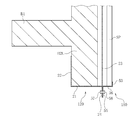
- the connecting mechanism 30 connecting the outer side surface plate portion 13 and the lower end outer surface plate portion 23 is located in the middle of the upper wall portion B2U, but the present invention is not limited to this, and for example, the mounting structure 102 shown in FIG. 6 may be used.
- the mounting structure 102 includes an upper end wall engaging metal fitting 110 (upper end wall engaging member) that engages with the upper wall portion B2U and a lower end wall engaging metal fitting 120 (lower end wall engaging member) that engages with the lower wall portion B2L.
- the connecting mechanism 30 for connecting the upper end wall engaging metal fitting 110 and the lower end wall engaging metal fitting 120, and the upper end wall engaging metal fitting 110 are connected to each other and held against the upper end portion of the solar panel SP (held member).
- the panel upper end holding metal fitting 140 (upper end holding structure) and the panel lower end holding metal fitting 50 (upper end holding structure) which are connected to the lower end wall engaging metal fitting 120 and hold the lower end of the solar panel SP. Be prepared.
- the upper end wall engaging metal fitting 110 includes an upper surface plate portion 111 arranged on the upper end surface of the upper wall portion B2U, an upper end inner side surface plate portion 112 connected to the upper surface plate portion 111, and an upper end outer surface plate portion connected to the upper surface plate portion 111. 113 and.
- the top plate portion 111 is arranged horizontally, the inner (left side in FIG. 6) end extends to the inner end in the Y direction of the upper end surface of the upper wall portion B2U, and the outer (right side in FIG. 6) end. , Extends to the outer edge of the upper end surface of the upper wall portion B2U in the Y direction.
- the upper end inner side surface plate portion 112 extends vertically downward from the inner end of the upper end plate portion 111. Therefore, the upper end inner side plate portion 112 is arranged along the inner side surface (left side in FIG. 6) of the upper wall portion B2U.
- the upper end outer face plate portion 113 extends vertically upward from the outer end of the
- the lower end wall engaging metal fitting 120 is connected to a lower surface plate portion 121 arranged along the lower end surface of the lower wall portion B2L and inside the lower end plate portion 121 and arranged along the inner side surface of the lower wall portion B2L.
- a face plate portion 122 and a lower end outer face plate portion 123 connected to the lower surface plate portion 121 and arranged along the outer side surface of the lower wall portion B2L are provided.
- the bottom plate portion 121 is arranged horizontally.
- the lower end inner side surface plate portion 122 and the lower end outer surface plate portion 123 are arranged vertically, respectively.
- the upper end of the lower end outer face plate portion 123 projects upward from the upper end of the upper end outer face plate portion 113.
- the upper end of the lower end inner side plate portion 122 is separated from the floor member B1.
- the connecting mechanism 30 includes a bolt hole 113a formed in the upper end outer face plate portion 113, a bolt hole 123a formed in the lower end outer face plate portion 123, and a bolt 33 compatible with the two bolt holes 113a and 123a.
- a nut 34 screwed into the bolt 33 is provided.
- the bolt hole 123a is formed at a position higher than the height (length in the Z direction) of the wall member B2 with reference to the lower end of the lower end outer face plate portion 123.
- the panel upper end holding metal fitting 140 is connected to the upper surface holding plate portion 142 arranged along the lower end outer surface plate portion 123 and the upper horizontal portion 143 which is connected to the lower end of the upper surface holding plate portion 142 and extends outward in the Y direction.
- An upper and outer vertical portion 144 extending downward in the Z direction from the outer end portion in the Y direction of the upper horizontal portion 143.
- the upper surface holding plate portion 142 and the upper outer vertical portion 144 are arranged vertically.
- the upper horizontal portion 143 is arranged horizontally.
- a gap may be formed between the lower end outer face plate portion 123 and the upper outer vertical portion 144 so that the upper end portion of the solar panel SP can be inserted.
- Bolt holes 123b are formed in the lower end outer face plate portion 123.
- the bolt hole 123b is preferably located above the bolt hole 123a.
- Bolt holes 142a are formed in the upper surface holding plate portion 142.
- the panel upper end holding metal fitting 140 further includes a bolt 47 that can be inserted into the bolt hole 123b and the bolt hole 142a, and a nut 48 that is screwed into the bolt 47.
- the bolt tightening work can be performed at a position above the wall member B2 and at the lower end of the wall member B2, so that workability is improved.
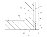
- the upper end of the lower end outer face plate portion 123 is located above the upper end of the upper end outer face plate portion 113, but the present invention is not limited to this. As shown in FIG. 7, the upper end of the upper end outer face plate portion 113 may be located above the upper end of the lower end outer face plate portion 123. In this case, instead of forming the bolt hole 123b in the lower end outer face plate portion 123, it is preferable to form the bolt hole 113b in the upper end outer face plate portion 113. The bolt hole 113b is located above the bolt hole 113a. Then, after inserting the bolt 47 into the bolt hole 113b and the bolt hole 142a, the nut 48 may be screwed into the bolt 47.
- the connecting mechanism 30 may connect the upper end wall engaging metal fitting 110 and the lower end wall engaging metal fitting 120 so that the upper end wall engaging metal fitting 110 and the lower end wall engaging metal fitting 120 can slide with each other. ..
- at least one of the bolt hole 113a and the bolt hole 123a is preferably an elongated hole.
- the elongated hole preferably extends in the Z direction.
- the panel upper end holding metal fitting 140 and the panel lower end holding metal fitting 50 may be slidable to each other.
- the bolt hole 142a is a long hole.
- the elongated hole preferably extends in the Z direction.
- the bolt holes formed in the lower end outer face plate portion 123 and the lower inner vertical portion 51 may be elongated holes extending in the Z direction.
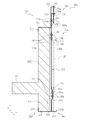
- the mounting structure 202 as shown in FIG. 8 may be used.
- the mounting structure 202 includes an upper end wall engaging metal fitting 210 (upper end wall engaging member) that engages with the upper wall portion B2U and a lower end wall engaging metal fitting 220 (lower end wall engaging member) that engages with the lower wall portion B2L.
- the panel upper end holding metal fitting 240 (upper end holding structure) and the panel lower end holding metal fitting 250 (upper end holding structure) which are connected to the lower end wall engaging metal fitting 220 and hold the lower end of the solar panel SP. Be prepared.
- the upper end wall engaging metal fitting 210 includes an upper surface plate portion 211 arranged on the upper end surface of the upper wall portion B2U, an upper end inner side surface plate portion 212 connected to the upper surface plate portion 211, and an upper end outer surface plate portion connected to the upper surface plate portion 211. 213 and.
- the top plate portion 211 is arranged horizontally, the inner end (left side in FIG. 8) extends to the inner end of the upper end surface of the upper wall portion B2U in the Y direction, and the outer end (right side in FIG. 8) is upper. It extends to the outer edge of the upper end surface of the wall B2U in the Y direction.
- the upper end inner side plate portion 212 extends vertically downward from the inner end of the upper end plate portion 211. Therefore, the upper end inner side plate portion 212 is arranged along the inner side surface of the upper wall portion B2U.
- the upper end outer face plate portion 213 extends vertically upward from the outer end of the upper end plate portion 211.
- the lower end wall engaging metal fitting 220 is connected to the lower surface plate portion 221 arranged along the lower end surface of the lower wall portion B2L and the lower end inner side arranged along the inner side surface of the lower wall portion B2L connected to the lower surface plate portion 221.
- a face plate portion 222 and a lower end outer face plate portion 223 connected to the lower surface plate portion 221 and arranged along the outer side surface of the lower wall portion B2L are provided.
- the bottom plate portion 221 is arranged horizontally.
- the lower end inner side surface plate portion 222 and the lower end outer side plate portion 223 are arranged vertically, respectively.
- the upper end of the lower end outer face plate portion 223 is located above the upper end of the upper wall portion B2U, but is located below the upper end of the upper end outer face plate portion 213.
- the connecting mechanism 230 includes a first connecting mechanism that connects the upper end wall engaging metal fitting 210 and the lower end wall engaging metal fitting 220 so as to be movable in the Z direction, and the upper end wall engaging metal fitting 210 and the lower end wall engaging metal fitting 220. It is provided with a second connecting mechanism that regulates the movement of the above in the Z direction.
- the first connecting mechanism includes an upper bent portion 231 formed in the upper end outer face plate portion 213, an upper bent portion 232 formed in the lower end outer face plate portion 223, and a bolt hole 231a formed in the upper bent portion 231.
- a bolt 233 for inserting a bolt hole 232a formed in the upper bent portion 232 and a nut 234 screwed into the bolt 233 are provided.
- the upper bent portion 231 and the upper bent portion 232 are each formed in a plate shape and extend horizontally.
- the bolt 233 is inserted into the bolt hole 231a and the bolt 232a hole from the upper side, and the nut 234 is inserted from the lower side of the bolt 233.
- the bolt 233 By tightening the bolt 233 so that the nut 234 approaches the bolt 233, the upper bent portion 231 and the upper bent portion 232 approach each other in the Z direction.
- the distance between the upper end outer face plate portion 213 and the lower end outer face plate portion 223 can be reduced in the Z direction.
- the upper bent portion 231 and the upper bent portion 232 move away from each other in the Z direction.
- the distance between the upper end outer face plate portion 213 and the lower end outer face plate portion 223 can be increased in the Z direction.
- the upper end wall engaging metal fitting 210 and the lower end wall engaging metal fitting 220 are connected so as to be movable in the Z direction.
- the second connecting mechanism includes a bolt hole 213a formed in the upper end outer face plate portion 213, a bolt hole 223a formed in the lower end outer face plate portion 223, a bolt 235 that communicates the bolt hole 213a and the bolt hole 223a, and a bolt 235.
- a nut 236, which is screwed into, is provided.
- the bolt hole 223a is located above the upper wall portion B2U.
- the panel upper end holding metal fitting 240 is connected to the upper surface holding plate portion 242 arranged along the lower end outer face plate portion 223 and the upper horizontal portion 243 which is connected to the lower end of the upper surface holding plate portion 242 and extends outward in the Y direction.
- the upper and outer vertical portions 244 extending downward in the Z direction from the outer end in the Y direction of the upper horizontal portion 243 are provided.
- the upper surface holding plate portion 242 and the upper outer vertical portion 244 are arranged vertically.
- the upper horizontal portion 243 is arranged horizontally.
- a gap may be formed between the lower end outer face plate portion 223 and the upper outer vertical portion 244 so that the upper end portion of the solar panel SP can be inserted.
- Bolt holes 223b are formed in the lower end outer face plate portion 223.
- the bolt hole 223b is located below the bolt hole 223a.
- Bolt holes 242a are formed in the upper surface holding plate portion 242.
- the panel upper end holding metal fitting 240 further includes a bolt 247 that can be inserted into the bolt hole 223b and the bolt hole 242a, and a nut 248 that is screwed into the bolt 247.
- the bolt hole 242a is an elongated hole extending in the Z direction. As a result, the panel upper end holding metal fitting 240 becomes relatively movable in the Z direction in a state of being connected to the lower end wall engaging metal fitting 220. When a plurality of bolt holes 242a are provided, it is preferable to provide them in the X direction.
- the panel lower end holding bracket 250 includes a lower inner vertical portion 251 arranged along the lower end outer face plate portion 223, a lower horizontal portion 252 extending outward in the Y direction from the lower end portion of the lower inner vertical portion 251 in the Z direction, and a lower horizontal portion.
- the upper and outer vertical portions 253 extending upward in the Z direction from the outer end portion in the Y direction of the portion 252 are provided.
- the lower inner vertical portion 251 and the upper outer vertical portion 253 are arranged vertically.
- the lower horizontal portion 252 is arranged horizontally.
- a gap may be formed between the lower inner vertical portion 251 and the upper outer vertical portion 253 to the extent that the lower end portion of the solar panel SP is inserted.
- an inner recessed portion 223t is formed in the middle portion in the Z direction inside the lower end outer face plate portion 223 (left side in FIG. 8).
- an engaging portion 251t that can be engaged with the outside (right side in FIG. 8) of the inner recessed portion 223t is formed in the middle portion in the Z direction of the lower inner vertical portion 251.
- a bolt hole 223c is formed in the inner recessed portion 223t, and a bolt hole 251a is formed in the engaging portion 251t.
- the panel lower end holding metal fitting 250 includes a bolt 257 that can be inserted into the bolt holes 223c and 251a, and a nut 258 that is screwed into the bolt 257.
- the amount of depression of the inner recessed portion 223t is preferably such that the head of the bolt 257 is accommodated when the wall member B2 and the lower end outer face plate portion 223 are brought close to each other.
- the wall member B2 and the lower end outer face plate portion 223 are brought close to each other so that the gap between the wall member B2 and the lower end outer face plate portion 223 becomes smaller than the size of the bolt 257, the fall of the bolt 257 is suppressed.
- the engaging portion 251t may extend in the X direction.
- the lower inner vertical portion 251 becomes movable in the X direction with respect to the lower end outer face plate portion 223. Further, the lower inner vertical portion 251 can be easily positioned in the Z direction with respect to the lower end outer face plate portion 223.
- the lower end wall engaging metal fitting 220 and the panel lower end holding metal fitting 250 are connected by the bolt 257 and the nut 258 in a state where the engaging portion 251t is engaged with the inner recessed portion 223t. Further, the lower end wall engaging metal fitting 220 and the panel upper end holding metal fitting 240 are connected by bolts 247 and nuts 248 in a movable state in the Z direction.
- the upper bent portion 231 and the upper bent portion 232 are separated from each other in the Z direction.
- the wall member B2 can be inserted between the upper end outer face plate portion 213 and the lower end outer face plate portion 223 in the Z direction. Then, the wall member B2 is inserted between the upper end outer face plate portion 213 and the lower end outer face plate portion 223 in the Z direction.
- the panel upper end holding metal fitting 240 is connected to the lower end wall engaging metal fitting 220 by the bolt 247 and the nut 248.
- the solar panel SP is fixed by the panel upper end holding metal fitting 240 and the panel lower end holding metal fitting 250 so as to be sandwiched from above and below (FIG. 8).
- the upper bent portion 231 and the upper bent portion 232 are relatively moved in the Z direction depending on the tightening condition of the bolt 233, but the present invention is not limited to this.
- either one of the bolt hole 213a and the bolt hole 223a may be an elongated hole extending in the Z direction.
- the upper bent portion 231 and the upper bent portion 232 can be relatively moved in the Z direction.
- the bolt 233 and the nut 234 regulate the relative movement of the upper bent portion 231 and the upper bent portion 232 in the Z direction.
- the bolt hole 223b may be located above the bolt hole 223a.
- the wall member B2 is provided in the direction perpendicular to the floor member B1, but the present invention is not limited to this, and the wall member B2 may be provided obliquely with respect to the floor member B1.
- the mounting structure 2 is mounted on the wall member B2 of the balcony, but the present invention is not limited to this, and the mounting structure 2 may be mounted on the plate-shaped member.
- the plate-shaped member include a waist wall of a staircase or a landing of a staircase, a wall member or a beam of a pedestrian bridge or a parking lot, and a pepperat.
- the attached member includes not only a plate-shaped member such as a solar panel SP, but also a photographing device such as a security camera, a lighting device, and the like.
- a photographing device such as a security camera or a lighting device
- a unit such as an upper end wall engaging metal fitting 10, a lower end wall engaging metal fitting 20, and a connecting mechanism 30.
- the panel upper end holding metal fitting 40 and the panel lower end holding metal fitting 50 may be omitted.
- a double nut in which a plurality of nuts 34, 48, 58 are screwed into one bolt 33, 47, 57, etc. may be adopted.
- the upper end wall engaging metal fitting, the lower end wall engaging metal fitting, the panel upper end holding metal fitting, and the lower end holding metal fitting are used as separate parts, but the present invention is not limited to this, and among these, the present invention is used.
- a plurality of parts may be integrated.
- the lower end wall engaging metal fitting and the lower end holding metal fitting may be integrated, or the upper end wall engaging metal fitting and the panel upper end holding metal fitting may be integrated.
Landscapes
- Engineering & Computer Science (AREA)
- Architecture (AREA)
- Civil Engineering (AREA)
- Structural Engineering (AREA)
- Finishing Walls (AREA)
- Steps, Ramps, And Handrails (AREA)
- Roof Covering Using Slabs Or Stiff Sheets (AREA)
Priority Applications (1)
| Application Number | Priority Date | Filing Date | Title |
|---|---|---|---|
| JP2022501100A JP7538393B2 (ja) | 2020-02-20 | 2021-02-22 | 取付構造及び取付方法 |
Applications Claiming Priority (2)
| Application Number | Priority Date | Filing Date | Title |
|---|---|---|---|
| JP2020-026965 | 2020-02-20 | ||
| JP2020026965 | 2020-02-20 |
Publications (1)
| Publication Number | Publication Date |
|---|---|
| WO2021167103A1 true WO2021167103A1 (ja) | 2021-08-26 |
Family
ID=77390862
Family Applications (1)
| Application Number | Title | Priority Date | Filing Date |
|---|---|---|---|
| PCT/JP2021/006517 Ceased WO2021167103A1 (ja) | 2020-02-20 | 2021-02-22 | 取付構造及び取付方法 |
Country Status (2)
| Country | Link |
|---|---|
| JP (1) | JP7538393B2 (https=) |
| WO (1) | WO2021167103A1 (https=) |
Cited By (1)
| Publication number | Priority date | Publication date | Assignee | Title |
|---|---|---|---|---|
| EP4651369A1 (en) * | 2024-05-17 | 2025-11-19 | Sunshare Power Technology Co., Ltd. | Photovoltaic bracket |
Citations (5)
| Publication number | Priority date | Publication date | Assignee | Title |
|---|---|---|---|---|
| JPS5522042U (https=) * | 1978-07-29 | 1980-02-13 | ||
| JP3029906U (ja) * | 1996-04-08 | 1996-10-18 | 株式会社リボール | 不燃無機質防水板 |
| JP2003336465A (ja) * | 2002-05-17 | 2003-11-28 | Taisei Corp | ルーバ型太陽電池ユニット及びその製造方法 |
| JP2006210304A (ja) * | 2005-01-31 | 2006-08-10 | Atsumi Fudosan & Corporation:Kk | ソーラーライト |
| JP3183550U (ja) * | 2013-03-06 | 2013-05-23 | 惠一郎 山崎 | 足場固定具 |
-
2021
- 2021-02-22 JP JP2022501100A patent/JP7538393B2/ja active Active
- 2021-02-22 WO PCT/JP2021/006517 patent/WO2021167103A1/ja not_active Ceased
Patent Citations (5)
| Publication number | Priority date | Publication date | Assignee | Title |
|---|---|---|---|---|
| JPS5522042U (https=) * | 1978-07-29 | 1980-02-13 | ||
| JP3029906U (ja) * | 1996-04-08 | 1996-10-18 | 株式会社リボール | 不燃無機質防水板 |
| JP2003336465A (ja) * | 2002-05-17 | 2003-11-28 | Taisei Corp | ルーバ型太陽電池ユニット及びその製造方法 |
| JP2006210304A (ja) * | 2005-01-31 | 2006-08-10 | Atsumi Fudosan & Corporation:Kk | ソーラーライト |
| JP3183550U (ja) * | 2013-03-06 | 2013-05-23 | 惠一郎 山崎 | 足場固定具 |
Cited By (1)
| Publication number | Priority date | Publication date | Assignee | Title |
|---|---|---|---|---|
| EP4651369A1 (en) * | 2024-05-17 | 2025-11-19 | Sunshare Power Technology Co., Ltd. | Photovoltaic bracket |
Also Published As
| Publication number | Publication date |
|---|---|
| JPWO2021167103A1 (https=) | 2021-08-26 |
| JP7538393B2 (ja) | 2024-08-22 |
Similar Documents
| Publication | Publication Date | Title |
|---|---|---|
| KR101987085B1 (ko) | 공동주택 건축물용 전기 케이블 트레이 | |
| US11098481B2 (en) | Canopy system and group suspension system therefore | |
| US7874708B1 (en) | T-bar mounting system | |
| CN202227644U (zh) | 一种三维可调式装饰墙板挂件装置 | |
| KR102170173B1 (ko) | 주차장용 레이스웨이의 내진 설치구조 | |
| JP5058269B2 (ja) | エレベータかご及びその据付方法 | |
| RU141888U1 (ru) | Устройство для крепления модуля фары | |
| KR102065022B1 (ko) | 건축용 천정 구조물 프레임 어셈블리 | |
| WO2021167103A1 (ja) | 取付構造及び取付方法 | |
| JP5392462B2 (ja) | 天井用補強ブレースの固定金具、および固定構造 | |
| KR102201489B1 (ko) | 건축용 케이블 트레이 고정장치 | |
| JP6892304B2 (ja) | パネル体の脱落防止具および該脱落防止具の固定方法 | |
| KR101281159B1 (ko) | 이중바닥판용 지지대 어셈블리 | |
| KR20150000296U (ko) | 글라스 커튼월용 유리 고정장치 | |
| US20190194930A1 (en) | Method of connecting and installing a building member | |
| KR20200071904A (ko) | 천장 행거 및 이를 갖는 경량철골 천장틀 | |
| KR101212230B1 (ko) | 천정 패널 고정용 행거 | |
| JP5638383B2 (ja) | エレベータのかご上手摺装置 | |
| US11796144B2 (en) | Systems and methods for mounting recessed light fixtures | |
| JP5405931B2 (ja) | 形状保持部材付き天井野縁、天井野縁ユニット及び天井面の構造 | |
| KR101208104B1 (ko) | 건축외장재 설치용 고정구 | |
| JP2009171793A (ja) | ケーブルラックの増設方法 | |
| KR200476065Y1 (ko) | 케이블 트레이용 트레이 | |
| JP6077241B2 (ja) | 屋内階段および段板固定金具 | |
| JP2017106198A (ja) | カーテンウォール |
Legal Events
| Date | Code | Title | Description |
|---|---|---|---|
| 121 | Ep: the epo has been informed by wipo that ep was designated in this application |
Ref document number: 21756230 Country of ref document: EP Kind code of ref document: A1 |
|
| NENP | Non-entry into the national phase |
Ref country code: DE |
|
| ENP | Entry into the national phase |
Ref document number: 2022501100 Country of ref document: JP Kind code of ref document: A |
|
| 122 | Ep: pct application non-entry in european phase |
Ref document number: 21756230 Country of ref document: EP Kind code of ref document: A1 |