WO2021166874A1 - ワイヤハーネス - Google Patents
ワイヤハーネス Download PDFInfo
- Publication number
- WO2021166874A1 WO2021166874A1 PCT/JP2021/005606 JP2021005606W WO2021166874A1 WO 2021166874 A1 WO2021166874 A1 WO 2021166874A1 JP 2021005606 W JP2021005606 W JP 2021005606W WO 2021166874 A1 WO2021166874 A1 WO 2021166874A1
- Authority
- WO
- WIPO (PCT)
- Prior art keywords
- wire
- electric wire
- exterior member
- electric
- tape
- Prior art date
- Legal status (The legal status is an assumption and is not a legal conclusion. Google has not performed a legal analysis and makes no representation as to the accuracy of the status listed.)
- Ceased
Links
Images


Classifications
-
- B—PERFORMING OPERATIONS; TRANSPORTING
- B60—VEHICLES IN GENERAL
- B60R—VEHICLES, VEHICLE FITTINGS, OR VEHICLE PARTS, NOT OTHERWISE PROVIDED FOR
- B60R16/00—Electric or fluid circuits specially adapted for vehicles and not otherwise provided for; Arrangement of elements of electric or fluid circuits specially adapted for vehicles and not otherwise provided for
- B60R16/02—Electric or fluid circuits specially adapted for vehicles and not otherwise provided for; Arrangement of elements of electric or fluid circuits specially adapted for vehicles and not otherwise provided for electric constitutive elements
- B60R16/0207—Wire harnesses
-
- H—ELECTRICITY
- H02—GENERATION; CONVERSION OR DISTRIBUTION OF ELECTRIC POWER
- H02G—INSTALLATION OF ELECTRIC CABLES OR LINES, OR OF COMBINED OPTICAL AND ELECTRIC CABLES OR LINES
- H02G3/00—Installations of electric cables or lines or protective tubing therefor in or on buildings, equivalent structures or vehicles
- H02G3/30—Installations of cables or lines on walls, floors or ceilings
- H02G3/32—Installations of cables or lines on walls, floors or ceilings using mounting clamps
-
- B—PERFORMING OPERATIONS; TRANSPORTING
- B60—VEHICLES IN GENERAL
- B60R—VEHICLES, VEHICLE FITTINGS, OR VEHICLE PARTS, NOT OTHERWISE PROVIDED FOR
- B60R16/00—Electric or fluid circuits specially adapted for vehicles and not otherwise provided for; Arrangement of elements of electric or fluid circuits specially adapted for vehicles and not otherwise provided for
- B60R16/02—Electric or fluid circuits specially adapted for vehicles and not otherwise provided for; Arrangement of elements of electric or fluid circuits specially adapted for vehicles and not otherwise provided for electric constitutive elements
- B60R16/0207—Wire harnesses
- B60R16/0215—Protecting, fastening and routing means therefor
-
- F—MECHANICAL ENGINEERING; LIGHTING; HEATING; WEAPONS; BLASTING
- F16—ENGINEERING ELEMENTS AND UNITS; GENERAL MEASURES FOR PRODUCING AND MAINTAINING EFFECTIVE FUNCTIONING OF MACHINES OR INSTALLATIONS; THERMAL INSULATION IN GENERAL
- F16B—DEVICES FOR FASTENING OR SECURING CONSTRUCTIONAL ELEMENTS OR MACHINE PARTS TOGETHER, e.g. NAILS, BOLTS, CIRCLIPS, CLAMPS, CLIPS OR WEDGES; JOINTS OR JOINTING
- F16B2/00—Friction-grip releasable fastenings
- F16B2/02—Clamps, i.e. with gripping action effected by positive means other than the inherent resistance to deformation of the material of the fastening
- F16B2/06—Clamps, i.e. with gripping action effected by positive means other than the inherent resistance to deformation of the material of the fastening external, i.e. with contracting action
- F16B2/08—Clamps, i.e. with gripping action effected by positive means other than the inherent resistance to deformation of the material of the fastening external, i.e. with contracting action using bands
-
- H—ELECTRICITY
- H01—ELECTRIC ELEMENTS
- H01B—CABLES; CONDUCTORS; INSULATORS; SELECTION OF MATERIALS FOR THEIR CONDUCTIVE, INSULATING OR DIELECTRIC PROPERTIES
- H01B7/00—Insulated conductors or cables characterised by their form
-
- H—ELECTRICITY
- H02—GENERATION; CONVERSION OR DISTRIBUTION OF ELECTRIC POWER
- H02G—INSTALLATION OF ELECTRIC CABLES OR LINES, OR OF COMBINED OPTICAL AND ELECTRIC CABLES OR LINES
- H02G3/00—Installations of electric cables or lines or protective tubing therefor in or on buildings, equivalent structures or vehicles
- H02G3/02—Details
- H02G3/04—Protective tubing or conduits, e.g. cable ladders or cable troughs
Definitions
- This disclosure relates to a wire harness.
- some wire harnesses mounted on a vehicle are provided with an electric wire for electrically connecting a plurality of electric devices and a clamp for fixing the electric wire to the vehicle body.
- some clamps include an elastic member through which an electric wire is inserted and a fixing member that holds the elastic member and fixes the elastic member to the vehicle body.
- the outer peripheral surface of the portion inserted through the elastic member is elastically held by the elastic member.
- An object of the present disclosure is to provide a wire harness capable of suppressing the electric wire from moving relative to the clamp in the axial direction of the electric wire.
- the wire harness of the present disclosure includes an electric wire, a covering member for covering the outer peripheral surface of the electric wire, and a clamp for fixing the electric wire to a vehicle body, and a large number of surfaces of the covering member on the opposite side of the electric wire are provided.
- the clamp is a wire having an elastic member made of an elastic body and in contact with the uneven surface, and a fixing member that presses the elastic member against the uneven surface and is fixed to the vehicle body. It is a harness.
- the wire harness of the present disclosure it is possible to prevent the electric wire from moving relative to the clamp in the axial direction of the electric wire.
- FIG. 1 is a schematic view showing a wire harness in one embodiment.
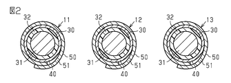
- FIG. 2 is an end view schematically showing the wire harness in one embodiment.
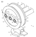
- FIG. 3 is a perspective view schematically showing the wire harness in one embodiment.
- FIG. 4 is a cross-sectional view schematically showing the wire harness in one embodiment.
- FIG. 5 is a schematic view showing a wire harness in a modified example.
- the wire harness of the present disclosure is [1] A wire, a covering member that covers the outer peripheral surface of the wire, and a clamp for fixing the wire to the vehicle body are provided, and the surface of the covering member on the opposite side of the wire has a large number of fine irregularities.
- the clamp is a wire harness having an elastic member made of an elastic body and in contact with the uneven surface, and a fixing member that presses the elastic member against the uneven surface and is fixed to the vehicle body.
- the covering member includes a tubular exterior member that covers the outer peripheral surface of the electric wire, and a tape member that is wound around the outer circumference of the exterior member and the outer circumference of the electric wire to fix the exterior member to the electric wire.
- the tape member is made of a woven fabric or a non-woven fabric and has a base material on which one surface in the thickness direction is coated with an adhesive, and the uneven surface is the other surface in the thickness direction of the base material. It is preferably a surface.
- the base material is made of woven fabric or non-woven fabric, an uneven surface can be easily provided on the tape member. Then, the tape member that fixes the exterior member to the electric wire has an uneven surface, and the elastic member is pressed against the uneven surface. Therefore, it is possible to further suppress the electric wire from moving relative to the clamp in the axial direction of the electric wire.
- the tape member is wound around the exterior member only at one end of both ends in the axial direction of the exterior member.
- the other end of both ends in the axial direction of the exterior member is not blocked by the tape member, so that it is in an open state. Therefore, the heat generated in the electric wire when the electric wire is energized can be released to the outside of the exterior member from the open end of the exterior member. As a result, the heat dissipation of the wire harness can be improved.
- the exterior member is preferably made of a sheet-shaped woven fabric or a sheet-shaped non-woven fabric.
- the exterior member made of a sheet-shaped woven fabric or a sheet-shaped non-woven fabric is superior in flexibility as compared with a synthetic resin corrugated tube or the like formed by using a molding die. Therefore, the degree of freedom in arranging the wire harness is increased. Further, since the exterior member is made of a woven fabric or a non-woven fabric, it has breathability. Therefore, the exterior member easily releases the heat generated in the electric wire to the outside when the electric wire is energized. Therefore, the heat dissipation of the wire harness can be further improved.
- a braided wire in which a conductive wire is woven into a tubular shape is provided, and the braided wire is arranged inside the exterior member and the tape member to cover the outer periphery of the electric wire.
- the braided wire is arranged inside the exterior member, the deformation of the electric wire to the outer peripheral side is regulated by the exterior member. Therefore, it is possible to prevent the braided wire from coming into contact with an object such as a device arranged around the wire harness.
- the covering member is made of a sheet-shaped woven fabric or a sheet-shaped non-woven fabric, and has a tubular exterior member that covers the outer peripheral surface of the electric wire, and the uneven surface is the outer peripheral surface of the exterior member. Is preferable.
- the exterior member is made of a woven fabric or a non-woven fabric, an uneven surface is easily formed on the outer peripheral surface of the exterior member. Then, since the elastic member is pressed against the uneven surface of the exterior member, the frictional force between the exterior member and the elastic member can be increased. Therefore, it is possible to easily prevent the electric wire from moving relative to the clamp in the axial direction of the electric wire.
- a braided wire in which a conductive wire is woven into a tubular shape is provided, a plurality of the electric wires are provided, the same number of covering members as the electric wires are provided, and each of the electric wires is individually coated on the covering member.
- the plurality of electric wires are collectively arranged inside the braided wire together with the covering member, and the elastic member is exposed to the outside of the braided wire from between the meshes formed by the strands. It is preferable to contact the uneven surface of the covering member.
- the wire harness 10 shown in FIG. 1 electrically connects electrical devices mounted on a vehicle.
- the wire harness 10 is mounted on a vehicle such as a hybrid vehicle or an electric vehicle, for example.
- the wire harness 10 includes a first conductive path 11, a second conductive path 12, a third conductive path 13, a connector 14 attached to one end of the conductive paths 11, 12, and 13, and a conductive path 11, 12, 13.
- a connector 15 attached to the other end of the 13 and a clamp 16 for fixing the conductive paths 11, 12, and 13 to the vehicle body are provided.
- the conductive paths 11, 12, and 13 are electrically connected to the electric device 21 via the connector 14 and electrically connected to the electric device 22 via the connector 15.
- the electric device 21 is an inverter 23 in this embodiment.
- the inverter 23 is electrically connected to a high voltage battery (not shown) capable of supplying a voltage of, for example, a hundred and several tens to several hundreds of volts.
- the inverter 23 generates AC power from the DC power of the high-voltage battery.
- the electric device 22 is a wheel driving motor 24 that is a power source for traveling the vehicle.
- the AC power generated by the inverter 23 is supplied to the motor 24 via the wire harness 10.
- each of the second conductive path 12 and the third conductive path 13 has the same configuration as the first conductive path 11. Therefore, the configuration of the first conductive path 11 will be described only.
- the second conductive path 12 and the third conductive path 13 are designated by the same reference numerals as those of the first conductive path 11 and the description thereof will be omitted.
- the first conductive path 11 includes one electric wire 30, one braided wire 40 covering the outer periphery of the electric wire 30, and a covering member 50 covering the outer peripheral surface of the electric wire 30.
- FIG. 2 is a 2-2 end view of FIG.
- the electric wire 30 is a coated electric wire having a core wire 31 made of a conductor and an insulating coating 32 that covers the outer circumference of the core wire 31.
- the core wire 31 includes, for example, a stranded wire made by twisting a plurality of metal strands, a columnar conductor made of one columnar metal rod having a solid structure inside, a tubular conductor having a hollow structure inside, and the like. Can be used. Further, as the core wire 31, for example, a combination of a plurality of types of conductors such as a stranded wire, a columnar conductor, and a tubular conductor can be used. Examples of the columnar conductor include a single core wire and a bass bar.
- the core wire 31 of this embodiment is a stranded wire.
- a metal material such as copper-based or aluminum-based can be used.
- the cross-sectional shape (that is, the cross-sectional shape) obtained by cutting the core wire 31 along a plane perpendicular to the length direction of the core wire 31, that is, the axial direction of the electric wire 30 can be any shape.
- the cross-sectional shape of the core wire 31 is formed, for example, into a circular shape, a semicircular shape, a polygonal shape, a square shape, a flat shape, or the like.
- the cross-sectional shape of the core wire 31 of the present embodiment is formed in a circular shape.
- the insulating coating 32 covers, for example, the outer peripheral surface of the core wire 31 over the entire circumferential direction.
- the insulating coating 32 has a cylindrical shape extending in the axial direction of the electric wire 30.
- the insulating coating 32 is made of an insulating material such as a synthetic resin.
- a synthetic resin containing a polyolefin resin such as cross-linked polyethylene or cross-linked polypropylene as a main component can be used.
- the material of the insulating coating 32 one kind of material may be used alone, or two or more kinds of materials may be used in combination as appropriate.
- the insulating coating 32 is removed from both ends of the electric wire 30 in the axial direction to expose the core wire 31.
- One end of the core wire 31 in the axial direction of the electric wire 30 is electrically connected to a connection terminal (not shown) provided on the connector 14.
- the other end of the core wire 31 in the axial direction of the electric wire 30 is electrically connected to a connection terminal (not shown) provided on the connector 15.
- the braided wire 40 is formed by weaving a conductive wire into a tubular shape. In each figure, the braided line 40 is shown in a simplified manner.
- the wire of this embodiment is a metal wire.
- As the material of the metal wire for example, a copper-based or aluminum-based metal material can be used.
- the braided wire 40 has flexibility.
- the electric wire 30 is arranged in the space inside the braided wire 40.
- the braided wire 40 covers the electric wire 30 from one end to the other end in the axial direction of the electric wire 30. Further, the braided wire 40 covers the outer peripheral surface of the electric wire 30 over the entire circumference in the circumferential direction.
- the braided wire 40 is in contact with the outer peripheral surface of the electric wire 30.
- One end of the braided wire 40 in the axial direction of the electric wire 30 is electrically connected to the conductive member of the connector 14.
- the other end of the braided wire 40 in the axial direction of the electric wire 30 is electrically connected to the conductive member of the connector 15.
- the covering member 50 of the present embodiment covers the outer peripheral surface of the electric wire 30 from the outside of the braided wire 40.
- the covering member 50 has a tubular shape extending along the axial direction of the electric wire 30 as a whole.
- the covering member 50 of the present embodiment is a tubular exterior member 51 that covers the outer peripheral surface of the electric wire 30, and a tape that is wound around the outer circumference of the exterior member 51 and the outer circumference of the electric wire 30 to fix the exterior member 51 to the electric wire 30. It has a member 52.
- the exterior member 51 has a tubular shape that extends along the axial direction of the electric wire 30 as a whole.
- the exterior member 51 is made of a sheet-shaped woven fabric or a sheet-shaped non-woven fabric. In the present embodiment, the exterior member 51 is formed by rolling a sheet-shaped woven fabric into a cylindrical shape.
- Examples of the material of the exterior member 51 include PE (polyester) fibers such as PET (polyethylene terephthalate) and aramid fibers.
- the material of the exterior member 51 is not limited to PE fiber and aramid fiber, and other fiber materials may be used.
- the exterior member 51 of the present embodiment is a twist tube made of PE fiber.
- the electric wire 30 and the braided wire 40 are arranged in the space inside the exterior member 51.
- the exterior member 51 of the present embodiment covers the outer peripheral surface of the electric wire 30 from the outside of the braided wire 40 by covering the electric wire 30 from the outside of the braided wire 40. Therefore, the braided wire 40 is arranged inside the exterior member 51 and covers the outer circumference of the electric wire 30.
- the exterior member 51 is attached to the electric wire 30 so that the axial direction of the exterior member 51 and the axial direction of the electric wire 30 substantially coincide with each other.
- the exterior member 51 covers the outer peripheral surface of the electric wire 30 over the entire circumference in the circumferential direction.
- the axial length of the exterior member 51 is shorter than the axial length of the electric wire 30 and the braided wire 40 of the electric wire 30. Further, in the present embodiment, the axial length of the exterior member 51 is shorter than the axial length of the insulating coating 32 of the electric wire 30. Both ends of the electric wire 30 and the braided wire 40 in the axial direction of the electric wire 30 project from both ends of the exterior member 51 in the axial direction to the outside of the exterior member 51. Further, in the present embodiment, both ends of the insulating coating 32 in the axial direction of the electric wire 30 project from both ends in the axial direction of the exterior member 51 to the outside of the exterior member 51.
- An adhesive tape 53 for suppressing the exterior member 51 from falling off from the electric wire 30 is wrapped around the central portion of the exterior member 51.
- the position where the adhesive tape 53 is wound on the exterior member 51 may be changed as appropriate. Further, the adhesive tape 53 may be omitted.
- the tape member 52 has a base material 54 made of a woven fabric or a non-woven fabric and having an adhesive coated on one surface in the thickness direction.
- FIG. 4 is a cross-sectional view taken along the line 4-4 in FIG.
- the base material 54 of this embodiment is made of a woven fabric.
- a woven fabric containing acetate fibers as a main component is used as the base material 54 of the present embodiment.
- the other surface of the base material 54 in the thickness direction is an uneven surface 55 having a large number of fine irregularities.
- the uneven surface 55 is a surface of the base material 54 opposite to the adhesive surface 56 coated with the adhesive.
- a large number of fine irregularities on the concave-convex surface 55 are formed because the base material 54 is made of a woven fabric. That is, a large number of fine irregularities on the concave-convex surface 55 are formed by the surface texture of the woven fabric.
- the tape member 52 is wound around the exterior member 51 only at one end of both ends in the axial direction of the exterior member 51.
- the tape member 52 is wound around both ends of the exterior member 51 in the axial direction, whichever is closer to the connector 14.
- the tape member 52 is not wound around both ends of the exterior member 51 in the axial direction, whichever is closer to the connector 15. Therefore, one end opening in the axial direction of the exterior member 51 closer to the connector 15 communicates with the inside and outside of the exterior member 51.
- the tape member 52 is spirally wound around the outer peripheral surface of the axial end of the exterior member 51 closer to the connector 14 and the outer periphery of the electric wire 30 and the braided wire 40 protruding from the end to the outside of the exterior member 51.
- the tape member 52 has a cylindrical shape that surrounds the outer circumference of the electric wire 30.
- the adhesive surface 56 of the tape member 52 adheres to the outer peripheral surface of the exterior member 51 and the braided wire 40.
- the uneven surface 55 of the tape member 52 faces the opposite side to the electric wire 30. That is, the surface of the tape member 52 wound in a cylindrical shape on the opposite side of the electric wire 30, that is, the outer peripheral surface of the tape member 52 is composed of the uneven surface 55.
- the clamp 16 fixes each electric wire 30 to the vehicle body.
- the clamp 16 includes a fixing member 60 fixed to the vehicle body panel 100 provided on the vehicle and an elastic member 70 pressed against the conductive paths 11, 12, 13 by the fixing member 60 from the outer peripheral side of the conductive paths 11, 12, 13. Has.
- the elastic member 70 is made of an elastic body.
- an elastomer can be used.
- a thermosetting elastomer such as EPDM (ethylene propylene diene rubber), silicone rubber, or butyl rubber can be used.
- EPDM ethylene propylene diene rubber
- silicone rubber or butyl rubber
- the elastic member 70 of the present embodiment is made of EPDM.
- the elastic member 70 has a disk shape.
- the elastic member 70 has three insertion holes 71, 72, 73 arranged in the radial direction.
- the insertion holes 71, 72, and 73 have a circular shape when viewed from the thickness direction of the elastic member 70.
- the first conductive path 11 is inserted through the insertion hole 71. Then, in the space inside the insertion hole 71, a portion around which the tape member 52 is wound is arranged in the first conductive path 11.
- the space inside the insertion hole 71 is a portion of the first conductive path 11 in which the electric wire 30, the braided wire 40, and the tape member 52 are layered, and the exterior member 51 does not overlap.
- the part is arranged.
- the inner peripheral surface of the insertion hole 71 can come into contact with the uneven surface 55 forming the outer peripheral surface of the tape member 52 in the first conductive path 11. That is, the elastic member 70 can come into contact with the uneven surface 55 included in the tape member 52 of the first conductive path 11.
- the second conductive path 12 is inserted through the insertion hole 72.
- a portion of the second conductive path 12 around which the tape member 52 is wound is arranged in the space inside the insertion hole 72.
- the space inside the insertion hole 72 is a portion of the second conductive path 12 in which the electric wire 30, the braided wire 40, and the tape member 52 form a layer, and the exterior member 51 does not overlap.
- the part is arranged.
- the inner peripheral surface of the insertion hole 72 can come into contact with the uneven surface 55 forming the outer peripheral surface of the tape member 52 in the second conductive path 12. That is, the elastic member 70 can come into contact with the uneven surface 55 included in the tape member 52 of the second conductive path 12.
- a third conductive path 13 is inserted through the insertion hole 73. Then, in the space inside the insertion hole 73, a portion around which the tape member 52 is wound is arranged in the third conductive path 13.
- the space inside the insertion hole 73 is a portion of the third conductive path 13 in which the electric wire 30, the braided wire 40, and the tape member 52 are layered, and the exterior member 51 does not overlap. The part is arranged.
- the inner peripheral surface of the insertion hole 73 can come into contact with the uneven surface 55 forming the outer peripheral surface of the tape member 52 in the third conductive path 13. That is, the elastic member 70 can come into contact with the uneven surface 55 included in the tape member 52 of the third conductive path 13.
- the inner diameters of the insertion holes 71, 72, 73 are set in the space inside the insertion holes 71, 72, 73 in the conductive paths 11, 12, 13. It may be smaller, equal to, or larger than the outer diameter of the portion to be arranged. However, the inner diameters of the insertion holes 71, 72, 73 are such that the inner peripheral surfaces of the insertion holes 71, 72, 73 are uneven surfaces 55 in the conductive paths 11, 12, 13 while the elastic member 70 is held by the fixing member 60. It is a size that can be pressed against the surface.
- the fixing member 60 has a fixing portion 61 fixed to the vehicle body panel 100 and a holding portion 62 for holding each electric wire 30.
- the fixing portion 61 is fixed to the vehicle body panel 100 to support the holding portion 62.
- the fixing portion 61 is fixed so as not to be relatively movable with respect to the vehicle body panel 100.
- the holding portion 62 includes a locking portion 63 supported by the fixing portion 61, a main body portion 64 that holds the elastic member 70 inside, and a tightening member 65 that fixes the main body portion 64 to the locking portion 63.
- a locking portion 63 supported by the fixing portion 61
- a main body portion 64 that holds the elastic member 70 inside
- a tightening member 65 that fixes the main body portion 64 to the locking portion 63.
- the main body 64 has a cylindrical shape as a whole.
- the inner diameter of the main body 64 is slightly smaller than the outer diameter of the elastic member 70.
- the main body portion 64 has a pair of holding bodies 66 in which the main body portion 64 is divided into two in the circumferential direction.
- Each holding body 66 has a semicircular arc shape when viewed from the axial direction of the main body portion 64.
- the two holding bodies 66 are connected by a flexible hinge 67 provided at one end in the radial direction of the main body 64.
- the two sandwiching bodies 66 can rotate relative to each other with the hinge 67 as the center of rotation.
- the two holding bodies 66 can be displaced into a closed state in which the two holding bodies 66 are cylindrical and an open state in which the ends of the two holding bodies 66 on the opposite side of the hinge 67 in the radial direction are separated from each other.
- the elastic member 70 is arranged inside the pair of holding bodies 66, that is, inside the main body portion 64.
- the main body 64 presses the elastic member 70 inward in the radial direction when the two holding bodies 66 are in the closed state. That is, the main body 64 presses the elastic member 70 against the uneven surfaces 55 of the conductive paths 11, 12, and 13 when the two sandwiching bodies 66 are in the closed state.
- the tightening member 65 has a strip shape. Both ends of the tightening member 65 in the longitudinal direction can be fixed to the locking portion 63.
- the tightening member 65 is wound around the outer peripheral surface of the main body portion 64 once, and both ends of the tightening member 65 in the longitudinal direction are fixed to the locking portion 63.
- the tightening member 65 tightens the main body 64 so that the two sandwiching bodies 66 maintain the closed state.
- the inner peripheral surface of the insertion hole 71 provided in the elastic member 70 is pressed against the uneven surface 55 of the tape member 52. That is, the elastic member 70 is pressed against the uneven surface 55. Therefore, the frictional force between the tape member 52 and the elastic member 70 becomes large.
- the tape member 52 and the braided wire 40 are pressed toward the electric wire 30 by the elastic member 70, so that the braided wire 40 becomes the insulating coating 32. Get into it. Therefore, the relative movement between the braided wire 40 and the electric wire 30 in the axial direction of the electric wire 30 is suppressed.
- the insulating coating 32 enters the inside of the mesh of the strands constituting the braided wire 40. Therefore, the outer peripheral surface of the insulating coating 32 moves relatively to the outer peripheral side with respect to the braided wire 40. Therefore, the adhesive surface 56 of the tape member 52 easily adheres to the insulating coating 32 exposed from the mesh of the strands constituting the braided wire 40. That is, the adhesive surface 56 of the tape member 52 easily adheres to the outer peripheral surface of the electric wire 30.
- the adhesive surface 56 of the tape member 52 adheres to the insulating coating 32 exposed from the mesh of the wire, so that the tape member 52 and the electric wire 30 move relative to each other in the axial direction of the electric wire 30, that is, in the axial direction of the electric wire 30.
- the relative movement between the covering member 50 and the electric wire 30 is suppressed.
- the adhesive surface 56 of the tape member 52 can adhere to the insulating coating 32 exposed from the mesh of the wires constituting the braided wire 40, so that the braided wire 40 is between the tape member 52 and the outer peripheral surface of the electric wire 30. Is arranged, the electric wire 30 is difficult to move relative to the covering member 50 in the axial direction of the electric wire 30.
- the adhesive surface 56 of the tape member 52 does not adhere to the outer peripheral surface of the electric wire 30.
- the adhesive surface 56 of the tape member 52 adheres to the outer peripheral surface of the electric wire 30 as described above.
- the exterior member 51 is fixed to the electric wire 30 by the adhesive surface 56 of the tape member 52 adhering to the insulating coating 32 exposed from the mesh of the strands constituting the braided wire 40.
- the adhesive surface 56 of the tape member 52 also adheres to the braided wire 40, so that the tape member 52 and the braided wire 40 move relative to each other in the axial direction of the electric wire 30, that is, the shaft of the electric wire 30. The relative movement of the exterior member 51 and the braided wire 40 in the direction is suppressed.
- the wire harness 10 includes an electric wire 30, a covering member 50 that covers the outer peripheral surface of the electric wire 30, and a clamp 16 for fixing the electric wire 30 to the vehicle body.
- the surface of the covering member 50 opposite to the electric wire 30 includes an uneven surface 55 having a large number of fine irregularities.
- the clamp 16 has an elastic member 70 made of an elastic body and in contact with the uneven surface 55, and a fixing member 60 that presses the elastic member 70 against the uneven surface 55 and is fixed to the vehicle body.
- the uneven surface 55 is provided on the tape member 52 constituting the covering member 50 in each of the conductive paths 11, 12, and 13. Then, by pressing the elastic member 70 against the uneven surface 55 of the tape member 52, it is possible to prevent the tape member 52 from moving relative to the elastic member 70 in the axial direction of the electric wire 30. Therefore, it is possible to prevent the conductive paths 11, 12, and 13 from moving relative to the clamp 16 in the axial direction of each electric wire 30. Therefore, in each of the conductive paths 11, 12, and 13, it is possible to prevent the electric wire 30 from moving relative to the clamp 16 in the axial direction of the electric wire 30.
- the covering member 50 is a tubular exterior member 51 that covers the outer peripheral surface of the electric wire 30, and a tape member that is wound around the outer circumference of the exterior member 51 and the outer circumference of the electric wire 30 to fix the exterior member 51 to the electric wire 30. It has 52 and.
- the tape member 52 has a base material 54 made of a woven fabric and having an adhesive coated on one surface in the thickness direction.
- the uneven surface 55 is the other surface of the base material 54 in the thickness direction.
- the base material 54 is made of a woven fabric, the uneven surface 55 is easily provided on the tape member 52. Then, the tape member 52 that fixes the exterior member 51 to the electric wire 30 has an uneven surface 55, and the elastic member 70 is pressed against the uneven surface 55. Therefore, it is possible to further prevent the electric wire 30 from moving with respect to the clamp 16 in the axial direction of the electric wire 30.
- the clamp 16 is attached to a portion around which the tape member 52 is wound in each of the conductive paths 11, 12, and 13.
- the tape member 52 has an adhesive surface 56 that adheres to the outer peripheral surface of the electric wire 30, so that it is difficult to move relative to the electric wire 30. Therefore, it is possible to more effectively suppress the electric wire 30 from moving relative to the clamp 16 in the axial direction of the electric wire 30.
- the tape member 52 is wound around the exterior member 51 only at one end of both ends in the axial direction of the exterior member 51.
- the other end of the both ends in the axial direction of the exterior member 51 is not closed by the tape member 52, so that it is in an open state.
- the ends of the exterior member 51 in the axial direction that are closer to the connector 15 are opened without being blocked by the tape member 52. Therefore, the heat generated in the electric wire 30 when the electric wire 30 is energized can be released to the outside of the exterior member 51 from the open end portion of the exterior member 51. As a result, the heat dissipation of the wire harness 10 can be improved.
- the exterior member 51 is made of a sheet-shaped woven fabric.
- the exterior member 51 made of a sheet-shaped woven fabric is more flexible than the synthetic resin corrugated tube formed by using a molding die. Therefore, each of the conductive paths 11, 12, and 13 can be bent with a larger curvature than the corrugated tube. Therefore, the degree of freedom in arranging the wire harness 10 is increased.
- the exterior member 51 is made of a woven fabric, it has breathability. Therefore, the exterior member 51 easily releases the heat generated in the electric wire 30 to the outside when the electric wire 30 is energized. Therefore, the heat dissipation of the wire harness 10 can be further improved.
- corrugated tubes may have sharp corners formed at the axial ends.
- the sheet-shaped woven fabric is softer than the corrugated tube, it is difficult to provide a sharp corner portion at the axial end portion of the exterior member 51. Therefore, when the wire harness 10 vibrates due to vibration during vehicle running or the like, it is possible to prevent the insulating coating 32 of the electric wire 30 from being scraped by the axial end portion of the exterior member 51. Further, since it is not necessary to provide a configuration for suppressing the insulating coating 32 from being scraped by the axial end portion of the exterior member 51, it is possible to suppress an increase in the number of parts and a complicated structure of the wire harness 10. ..
- the exterior member 51 covers the outer circumference of the braided wire 40. Since it is difficult to provide sharp corners at the axial ends of the exterior member 51, when the wire harness 10 vibrates due to vibration during vehicle running or the like, the braided wire 40 is connected by the axial ends of the exterior member 51. It is suppressed that the constituent wires are cut. Further, since it is not necessary to provide a configuration for suppressing the wire forming the braided wire 40 from being cut by the axial end portion of the exterior member 51, the number of parts is increased and the structure of the wire harness 10 is increased. It is possible to suppress the complexity of.
- the wire harness 10 includes a braided wire 40 in which a conductive wire is woven into a tubular shape.
- the braided wire 40 is arranged inside the exterior member 51 and the tape member 52 and covers the outer circumference of the electric wire 30.
- the braided wire 40 is arranged inside the exterior member 51, the deformation of the electric wire 30 toward the outer circumference is regulated by the exterior member 51. Therefore, it is possible to prevent the braided wire 40 from coming into contact with an object such as a device arranged around the wire harness 10. As a result, it is possible to prevent the strands constituting the braided wire 40 from being cut by coming into contact with an object around the wire harness 10, so that it is possible to prevent the braided wire 40 from deteriorating its shielding performance. Further, it is possible to suppress the generation of abnormal noise caused by the braided wire 40 coming into contact with an object around the wire harness 10.
- the braided wire 40 can come into contact with the outer peripheral surface of the electric wire 30.
- the braided wire 40 of the present embodiment is made of a metal wire. Therefore, the heat generated in the electric wire 30 when the electric wire 30 is energized can be easily transferred from the electric wire 30 toward the braided wire 40. Therefore, the heat dissipation of the wire harness 10 can be further improved.
- This embodiment can be implemented by changing as follows.
- the present embodiment and the following modified examples can be implemented in combination with each other within a technically consistent range.
- the braided wire 40 may be a braided wire formed by combining a metal wire and a resin wire. That is, the braided wire 40 may be one in which a metal wire and a resin wire are woven into a tubular shape.
- the material of the metal wire for example, a copper-based or aluminum-based metal material can be used as in the above embodiment.
- the resin wire for example, a reinforcing fiber having excellent insulating properties and shear resistance such as a para-aramid fiber can be used.
- the exterior member 51 is not limited to a sheet-shaped woven fabric or a sheet-shaped non-woven fabric.
- the exterior member 51 may be a tubular one that covers the outer peripheral surface of the electric wire 30.
- the exterior member 51 may be, for example, a flexible corrugated tube.
- the tape member 52 may be wound around both ends of the exterior member 51 in the axial direction. That is, both ends of the exterior member 51 in the axial direction may be fixed to the electric wire 30 by the tape member 52.
- the base material 54 of the tape member 52 does not have to be mainly composed of acetate fibers as long as it is made of a woven fabric or a non-woven fabric.
- the covering member 50 has an exterior member 51 and a tape member 52.
- the covering member 50 does not have to include the exterior member 51. That is, the covering member 50 may be made of a tape member 52.
- the elastic member 70 presses the outer peripheral surface of the portion of the tape member 52 wound around the outer circumference of the electric wire 30 and the braided wire 40. Therefore, the clamp 16 holds a portion around which the tape member 52 is wound in each of the conductive paths 11, 12, and 13, and a portion where the exterior member 51 is not arranged.
- the portion held by the clamp 16 in each of the conductive paths 11, 12, and 13 is not limited to this.
- the elastic member 70 may be pressed against a portion of the exterior member 51 of the above embodiment where the tape member 52 is not wound. That is, the elastic member 70 may be pressed against the outer peripheral surface of the exterior member 51.
- the outer peripheral surface of the exterior member 51 becomes an uneven surface having a large number of fine irregularities.
- the outer peripheral surface of the exterior member 51 becomes an uneven surface because it is made of, for example, a sheet-shaped woven fabric or a sheet-shaped non-woven fabric.
- vinyl tape or the like can be used as the tape member 52.
- the covering member 50 does not have to include the tape member 52.
- the exterior member 51 is made of a woven fabric or a non-woven fabric, an uneven surface is easily formed on the outer peripheral surface of the exterior member 51. Then, since the elastic member 70 is pressed against the uneven surface of the exterior member 51, the frictional force between the exterior member 51 and the elastic member 70 can be increased. Therefore, it is possible to easily prevent the electric wire 30 from moving relative to the clamp 16 in the axial direction of the electric wire 30.
- the elastic member 70 may be pressed against a portion of the covering member 50 of the above embodiment in which the tape member 52 is wound around the outer circumference of the exterior member 51. That is, the elastic member 70 may be pressed against the outer peripheral surface of the tape member 52 at the portion where the exterior member 51 and the tape member 52 overlap in the radial direction of the electric wire 30. Even in this way, since the elastic member 70 is pressed against the uneven surface 55 of the covering member 50, the frictional force between the covering member 50 and the elastic member 70 becomes large. Therefore, it becomes difficult for the covering member 50 covering the outer peripheral surface of the electric wire 30 to move relative to the clamp 16 in the axial direction of the electric wire 30. As a result, it is possible to prevent the electric wire 30 from moving relative to the clamp 16 in the axial direction of the electric wire 30.
- each of the three electric wires 30 is individually covered with a braided wire 40.
- a plurality of electric wires 30 individually coated on the covering member 50 may be collectively covered by one braided wire 40.
- the wire harness 10 includes the same number of covering members 50 as the electric wires 30.
- the plurality of electric wires 30 are collectively arranged inside the braided wire 40 together with the covering member 50.
- the uneven surface of each covering member 50 is exposed to the outside of the braided wire 40 from between the meshes formed by the strands constituting the braided wire 40.
- the uneven surface may be provided on the outer peripheral surface of the exterior member 51, or may be provided on the surface of the tape member 52.
- the elastic member 70 comes into contact with the uneven surface of each covering member 50 exposed to the outside of the braided wire 40 from between the meshes formed by the strands.
- the elastic member 70 comes into contact with the braided wire 40, which is a member arranged in a layer on the outer peripheral side of the electric wire 30 other than the clamp 16, and is the same braided wire. 40 is pressed toward the electric wire 30. Therefore, the braided wire 40 can bite into the elastic member 70. Therefore, the braided wire 40 is suppressed from moving relative to the clamp 16 in the axial direction of the electric wire 30. As a result, it is possible to further suppress the electric wire 30 arranged inside the braided wire 40 from moving relative to the clamp 16 in the axial direction of the electric wire 30.
- the clamp 16 presses the braided wire 40, which is a member arranged on the outermost side of the members provided in layers on the outer periphery of the electric wire 30 other than the clamp 16, toward the electric wire 30. Therefore, the deformation of the braided wire 40 toward the outer circumference is suppressed by the clamp 16. Therefore, when the wire harness 10 vibrates due to vibration during vehicle running or the like, it is possible to prevent the braided wire 40 from coming into contact with an object such as a device arranged around the wire harness 10, so that the braided wire 40 is a wire. It is possible to suppress the generation of abnormal noise caused by contact with an object around the harness 10.
- the wire harness 10 does not necessarily have to include the braided wire 40.
- at least one of the conductive paths 11, 12, and 13 may be configured not to include the braided wire 40.
- the covering member 50 can directly cover the outer peripheral surface of the electric wire 30 without interposing a member between the covering member 50 and the electric wire 30.
- the configuration of the clamp 16 is not limited to the configuration of the above embodiment.
- the clamp 16 may have an elastic member made of an elastic body and in contact with the uneven surface 55 of the covering member 50, and a fixing member 60 that presses the elastic member against the uneven surface 55 and is fixed to the vehicle body.
- each of the two sandwiching bodies 66 may have a flat plate shape.
- the elastic member 70 may be formed so as to have a quadrangular outer shape so that it can be easily sandwiched between two sandwiching bodies 66 facing each other.
- the elastic member 70 is not provided with the insertion holes 71, 72, 73, and is interposed between the conductive paths 11, 12, 13 and the sandwiching body 66 in the opposite direction of the two sandwiching bodies 66. You may. In this case, butyl tape can also be used as the material of the elastic member 70.
- each electric wire 30 is a non-shielded electric wire that does not have an electromagnetic shield structure by itself.
- each electric wire 30 may be a shielded electric wire having an electromagnetic shield structure itself.
- the three conductive paths 11, 12, and 13 have the same configuration.
- the conductive paths 11, 12, and 13 may have different configurations from each other.
- the surface of the covering member 50 on the opposite side of the electric wire 30 includes an uneven surface having a large number of fine irregularities.
- the number of electric wires 30 included in the wire harness 10 is not limited to three, and may be one or more.
- the inverter 23 and the motor 24 are given as examples as the electric devices 21 and 22 connected by the wire harness 10.
- the electric devices 21 and 22 connected by the wire harness 10 are not limited to this, and may be any electric devices mounted on the vehicle.
- the electrical equipment also includes a control device and the like.
- the wire harness 10 may be used to connect the inverter 23 and the high voltage battery.
- the wire harness 10 may be used to connect a low-voltage battery capable of supplying a voltage lower than that of the high-voltage battery (for example, 12 volts) to an electric device connected to the low-voltage battery.
- the wire harness 10 may be used to connect the low voltage battery and the air conditioner.
- a plurality of electric wires 30 are arranged side by side in a direction orthogonal to the axial direction of the electric wires 30.
- the positions of the tape members 52 in the axial direction of the electric wire 30 overlap each other in the direction orthogonal to the axial direction of the electric wire 30.
- the plurality of electric wires 30 are fixed to the vehicle body by, for example, one clamp 16.
- the clamp 16 may be provided at the first length position in the total length of the wire harness 10.
- the first length position may be, for example, between the connector 14 and the open end of the exterior member 51.
- the tape member 52 of the embodiment may be referred to as an insulating fiber tape.
- the acetate fibers of the embodiment may be referred to as insulating fibers.
- the elastic member 70 has a plurality of electric wires 30 (or conductive paths 11, 12, 13) in the radial direction so that the plurality of electric wires 30 (or conductive paths 11, 12, 13) do not come into contact with each other. It may be configured to be separated and may be referred to as a spacer.
- the present disclosure includes the following aspects. Reference symbols have been added to some of the components of the exemplary embodiments, not for limitation, but as an aid to understanding. Some of the items described in the following embodiments may be omitted, or some of the items described in the embodiments may be selected or extracted and combined.
- the covering member (50) may cover the outer peripheral surface of the electric wire (30) in a state where the relative movement with respect to the electric wire (30) is suppressed.
- the covering member (50) has a tubular exterior member (51) that covers the outer peripheral surface of the electric wire (30) and a tape member (52).
- the tape member (51) is wound around both the outer circumference of the exterior member (51) and the outer circumference of the electric wire (30), whereby the exterior member (51) is wound around the electric wire (30). It may be fixed.
- the concavo-convex surface (55) may have concavo-convex size such that it adheres tightly to the elastic member (70).
- a large number of fine irregularities on the concave-convex surface (55) may be formed by the surface texture of the woven fabric or the non-woven fabric.
- a wire harness (10) is With multiple wires (30), A plurality of covering members (50) that cover the outer peripheral surfaces of the plurality of electric wires (30), and A clamp (16) for fixing the plurality of electric wires (30) to the vehicle body is provided.
- the surface of each covering member (50) opposite to the electric wire (30) includes an uneven surface (55) having a large number of fine irregularities.
- the plurality of electric wires (30) are arranged side by side in the radial direction of the electric wire (30). The positions of the uneven surfaces (55) of the plurality of covering members (50) in the axial direction of the electric wire (30) overlap each other in the radial direction of the electric wire (30).
- the clamp (16) has an elastic member (70) that is made of an elastic body and is in contact with each of the uneven surfaces (55) of the plurality of covering members (55), and the elastic member (70) is attached to the uneven surface (55). ), And a wire harness (10) having a fixing member (60) fixed to the vehicle body.
- the wire harness (10) is Electric wire (30) and A clamp (16) provided at a first length position of the wire harness (10) for fixing the electric wire (30) to the vehicle body and at least the first length position of the wire harness (10).
- Insulating fiber tape (52) having a radial inward surface that adheres to or adheres to the radial outward surface of the electric wire (30).
- the clamp (16) A fixing member (60) configured to be fixedly attached to the vehicle body, and An elastic member (70) that comes into contact with the radial outward surface of the insulating fiber tape (52) may be provided.
- the clamp (16) presses the elastic member (70) toward the radial outward surface of the insulating fiber tape (52) at the first length position of the wire harness (10).
- the elastic member (70) and the insulating fiber of the insulating fiber tape (52) may be configured to engage with each other in a concavo-convex manner.
- the wire harness (10) is With multiple wires (30), A clamp (16) provided at a first length position of the wire harness (10) for fixing the plurality of electric wires (30) to the vehicle body, and at least the first length of the wire harness (10).
- a plurality of insulating fiber tapes (52) having a plurality of radial inward surfaces (55) that adhere to or adhere to a plurality of radial outward surfaces of the plurality of electric wires (30) at the vertical positions.
- the clamp (16) attaches the elastic member (70) to the plurality of radial outward surfaces (55) of the plurality of insulating fiber tapes (52) at the first length position of the wire harness (10).
- the elastic member (70) and the insulating fibers of the insulating fiber tapes (52) may be configured to engage with each other in a concavo-convex manner.
- the radial inward surface of the insulating fiber tape (52) and the radial outward surface of the electric wire (30) do not move relative to each other in the axial and radial directions. As described above, the radial inward surface of the insulating fiber tape (52) may be in close contact with or adhered to the radial outward surface of the electric wire (30).
- the radial inward surface of the insulating fiber tape (52) may be an adhesive surface containing an adhesive, which is outside the radial direction of the insulating fiber tape (52).
- the facing surface may be a non-adhesive surface that does not contain an adhesive.
- the insulating fiber of the insulating fiber tape (52) may be an acetate fiber.
- the clamp (16) is the elastic member (70) and the elastic member (70) between the fixing member (60) and the radial outward surface of the electric wire (30). It may be configured to compress the insulating fiber tape (52).
- the fixing member (60) of the clamp (16) bundles the plurality of electric wires (30) at the first length position of the wire harness (10). Well and / or may traverse the plurality of wires (30).
- the elastic member (70) of the clamp (16) is such that the plurality of electric wires (30) are in contact with each other at the first length position of the wire harness (10). It may be a spacer that separates the plurality of electric wires (30) in the radial direction so as not to prevent them.
- the wire harness (10) may have an exterior member (51) that covers a predetermined length range of the wire (30).
- the exterior member (51) does not cover the electric wire (30) at the first length position of the wire harness (10), and the end of the exterior member (51).
- the exterior member (51) allows the radial inward surface of the exterior member (51) to move playfully with respect to the radial outward surface of the wire (30) in the intermediate portion excluding the portion. ) And the electric wire (30) may be connected.
- the wire harness (10) may have connectors (14, 15) at at least one end of the wire (30).
- the first length position of the wire harness (10) may be between the connector (14, 15) and the exterior member (51).
- Wire harness 11 1st conductive path 12 2nd conductive path 13 3rd conductive path 14 Connector 15 Connector 16 Clamp 21 Electrical equipment 22 Electrical equipment 23 Inverter 24 Motor 30 Electric wire 31 Core wire 32 Insulation coating 40 Braided wire 50 Coating member 51 Exterior member 52 Tape member 53 Adhesive tape 54 Base material 55 Concavo-convex surface 56 Adhesive surface 60 Fixing member 61 Fixing part 62 Holding part 63 Locking part 64 Main body 65 Tightening member 66 Holding body 67 Hinge 70 Elastic member 71 Insertion hole 72 Insertion hole 73 Insertion hole 100 Body panel
Landscapes
- Engineering & Computer Science (AREA)
- Mechanical Engineering (AREA)
- Architecture (AREA)
- Civil Engineering (AREA)
- Structural Engineering (AREA)
- General Engineering & Computer Science (AREA)
- Details Of Indoor Wiring (AREA)
- Installation Of Indoor Wiring (AREA)
- Clamps And Clips (AREA)
- Insulated Conductors (AREA)
Priority Applications (3)
| Application Number | Priority Date | Filing Date | Title |
|---|---|---|---|
| US17/800,420 US12296762B2 (en) | 2020-02-20 | 2021-02-16 | Wire harness |
| CN202180014734.3A CN115136429B (zh) | 2020-02-20 | 2021-02-16 | 线束 |
| JP2022501888A JP7396453B2 (ja) | 2020-02-20 | 2021-02-16 | ワイヤハーネス |
Applications Claiming Priority (2)
| Application Number | Priority Date | Filing Date | Title |
|---|---|---|---|
| JP2020-027197 | 2020-02-20 | ||
| JP2020027197 | 2020-02-20 |
Publications (1)
| Publication Number | Publication Date |
|---|---|
| WO2021166874A1 true WO2021166874A1 (ja) | 2021-08-26 |
Family
ID=77391197
Family Applications (1)
| Application Number | Title | Priority Date | Filing Date |
|---|---|---|---|
| PCT/JP2021/005606 Ceased WO2021166874A1 (ja) | 2020-02-20 | 2021-02-16 | ワイヤハーネス |
Country Status (4)
| Country | Link |
|---|---|
| US (1) | US12296762B2 (https=) |
| JP (1) | JP7396453B2 (https=) |
| CN (1) | CN115136429B (https=) |
| WO (1) | WO2021166874A1 (https=) |
Cited By (1)
| Publication number | Priority date | Publication date | Assignee | Title |
|---|---|---|---|---|
| US11342690B2 (en) * | 2018-08-01 | 2022-05-24 | Autonetworks Technologies, Ltd. | Fixing structure of splice part |
Citations (4)
| Publication number | Priority date | Publication date | Assignee | Title |
|---|---|---|---|---|
| JP2003061222A (ja) * | 2001-07-30 | 2003-02-28 | Three M Innovative Properties Co | 筒形被覆材及び被覆材キット |
| JP2009068515A (ja) * | 2007-09-10 | 2009-04-02 | Honda Motor Co Ltd | 長尺部材の保持構造 |
| JP2015104977A (ja) * | 2013-11-29 | 2015-06-08 | コベルコ建機株式会社 | 作業機械の索状体保持具 |
| WO2019188515A1 (ja) * | 2018-03-27 | 2019-10-03 | 住友電装株式会社 | ワイヤハーネス |
Family Cites Families (15)
| Publication number | Priority date | Publication date | Assignee | Title |
|---|---|---|---|---|
| JPH01136518A (ja) * | 1987-11-19 | 1989-05-29 | Sumitomo Electric Ind Ltd | 通信ケーブルの外被把持部 |
| JPH07123565A (ja) * | 1993-10-22 | 1995-05-12 | Sumitomo Wiring Syst Ltd | ワイヤハーネス用コルゲートチューブ |
| JPH1189057A (ja) * | 1997-09-08 | 1999-03-30 | Sumitomo Wiring Syst Ltd | ワイヤハーネス端部より分岐した電線群の結束具 |
| US8701716B2 (en) * | 2008-02-29 | 2014-04-22 | Federal-Mogul Corporation | Protective textile sleeve having high edge abrasion resistance and method of construction |
| US8747582B2 (en) * | 2008-09-05 | 2014-06-10 | Federal-Mogul Powertrain, Inc. | Self-wrapping textile sleeve with protective coating and method of construction thereof |
| EP2606168B1 (en) * | 2010-08-16 | 2014-03-26 | Federal-Mogul Powertrain, Inc. | Non-kinking self-wrapping woven sleeve and method of construction thereof |
| CN104246037B (zh) * | 2012-03-01 | 2016-03-30 | 费德罗-莫格尔动力系公司 | 卷包的端部耐磨防护的纺织套筒及其制造方法 |
| JP2013229408A (ja) * | 2012-04-25 | 2013-11-07 | Auto Network Gijutsu Kenkyusho:Kk | ワイヤハーネス |
| CA2963410A1 (en) * | 2014-10-03 | 2016-04-07 | Adelwiggings Group | Tucked cushion clamp and process of making a tucked cushion clamp |
| CN204651860U (zh) * | 2015-05-09 | 2015-09-16 | 韩光伟 | 一种带凸点的低阻耐磨夹砂塑钢复合电缆导管 |
| JP6454312B2 (ja) * | 2016-09-05 | 2019-01-16 | 矢崎総業株式会社 | ワイヤハーネス |
| US11826537B2 (en) * | 2017-01-23 | 2023-11-28 | Uwm Research Foundation | Medical tubing organizer |
| US10953824B2 (en) | 2017-03-16 | 2021-03-23 | Sumitomo Wiring Systems, Ltd. | Wire routing structure |
| US10615581B2 (en) * | 2017-04-04 | 2020-04-07 | Federal-Mogul Powertrain, Llc | Woven EMI and abrasion resistant sleeve and method of construction thereof |
| CN207625222U (zh) * | 2017-11-07 | 2018-07-17 | 惠州富盛绝缘材料有限公司 | 一种新型耐高温耐磨防滑套管 |
-
2021
- 2021-02-16 CN CN202180014734.3A patent/CN115136429B/zh active Active
- 2021-02-16 JP JP2022501888A patent/JP7396453B2/ja active Active
- 2021-02-16 WO PCT/JP2021/005606 patent/WO2021166874A1/ja not_active Ceased
- 2021-02-16 US US17/800,420 patent/US12296762B2/en active Active
Patent Citations (4)
| Publication number | Priority date | Publication date | Assignee | Title |
|---|---|---|---|---|
| JP2003061222A (ja) * | 2001-07-30 | 2003-02-28 | Three M Innovative Properties Co | 筒形被覆材及び被覆材キット |
| JP2009068515A (ja) * | 2007-09-10 | 2009-04-02 | Honda Motor Co Ltd | 長尺部材の保持構造 |
| JP2015104977A (ja) * | 2013-11-29 | 2015-06-08 | コベルコ建機株式会社 | 作業機械の索状体保持具 |
| WO2019188515A1 (ja) * | 2018-03-27 | 2019-10-03 | 住友電装株式会社 | ワイヤハーネス |
Cited By (1)
| Publication number | Priority date | Publication date | Assignee | Title |
|---|---|---|---|---|
| US11342690B2 (en) * | 2018-08-01 | 2022-05-24 | Autonetworks Technologies, Ltd. | Fixing structure of splice part |
Also Published As
| Publication number | Publication date |
|---|---|
| US12296762B2 (en) | 2025-05-13 |
| CN115136429B (zh) | 2024-08-20 |
| JPWO2021166874A1 (https=) | 2021-08-26 |
| JP7396453B2 (ja) | 2023-12-12 |
| CN115136429A (zh) | 2022-09-30 |
| US20230079073A1 (en) | 2023-03-16 |
Similar Documents
| Publication | Publication Date | Title |
|---|---|---|
| JP5935787B2 (ja) | ワイヤハーネス及びワイヤハーネス製造方法 | |
| WO2012157771A1 (ja) | シールド電線 | |
| JP7331619B2 (ja) | ワイヤハーネス | |
| US20180339667A1 (en) | Exterior wiring harness | |
| JP6110229B2 (ja) | シールドハーネス及びその製造方法 | |
| JP2021145414A (ja) | 防水ユニット及びワイヤハーネス | |
| US12014845B2 (en) | Composite cable | |
| JP7396453B2 (ja) | ワイヤハーネス | |
| JP7585097B2 (ja) | ワイヤハーネス | |
| JP7180752B2 (ja) | ワイヤハーネス | |
| JP7367559B2 (ja) | ワイヤハーネス | |
| JP7848653B2 (ja) | ワイヤハーネス | |
| US20200286647A1 (en) | Composite cable and composite harness | |
| CN114927275B (zh) | 线束 | |
| CN113243069A (zh) | 夹持件及带夹持件的线束 | |
| CN111837201A (zh) | 线束 | |
| JP2020113468A (ja) | 伝送用の電力線構造 | |
| JP7536828B2 (ja) | ワイヤハーネス | |
| JP7320931B2 (ja) | ワイヤーハーネス | |
| JP7816212B2 (ja) | 電線固定部材 | |
| US20200106248A1 (en) | Electromagnetic shield component, wire harness, and method for manufacturing electromagnetic shield component | |
| WO2022114090A1 (ja) | ワイヤハーネス | |
| CN114927999B (zh) | 线束 | |
| WO2025173701A1 (ja) | ワイヤハーネス | |
| WO2023181908A1 (ja) | ワイヤハーネス |
Legal Events
| Date | Code | Title | Description |
|---|---|---|---|
| 121 | Ep: the epo has been informed by wipo that ep was designated in this application |
Ref document number: 21756998 Country of ref document: EP Kind code of ref document: A1 |
|
| ENP | Entry into the national phase |
Ref document number: 2022501888 Country of ref document: JP Kind code of ref document: A |
|
| NENP | Non-entry into the national phase |
Ref country code: DE |
|
| 122 | Ep: pct application non-entry in european phase |
Ref document number: 21756998 Country of ref document: EP Kind code of ref document: A1 |
|
| WWG | Wipo information: grant in national office |
Ref document number: 17800420 Country of ref document: US |