WO2021166658A1 - 車載ecu、プログラム及び情報処理方法 - Google Patents
車載ecu、プログラム及び情報処理方法 Download PDFInfo
- Publication number
- WO2021166658A1 WO2021166658A1 PCT/JP2021/004075 JP2021004075W WO2021166658A1 WO 2021166658 A1 WO2021166658 A1 WO 2021166658A1 JP 2021004075 W JP2021004075 W JP 2021004075W WO 2021166658 A1 WO2021166658 A1 WO 2021166658A1
- Authority
- WO
- WIPO (PCT)
- Prior art keywords
- vehicle
- threshold value
- value
- signal
- ecu
- Prior art date
- Legal status (The legal status is an assumption and is not a legal conclusion. Google has not performed a legal analysis and makes no representation as to the accuracy of the status listed.)
- Ceased
Links
Images


Classifications
-
- B—PERFORMING OPERATIONS; TRANSPORTING
- B60—VEHICLES IN GENERAL
- B60R—VEHICLES, VEHICLE FITTINGS, OR VEHICLE PARTS, NOT OTHERWISE PROVIDED FOR
- B60R16/00—Electric or fluid circuits specially adapted for vehicles and not otherwise provided for; Arrangement of elements of electric or fluid circuits specially adapted for vehicles and not otherwise provided for
- B60R16/02—Electric or fluid circuits specially adapted for vehicles and not otherwise provided for; Arrangement of elements of electric or fluid circuits specially adapted for vehicles and not otherwise provided for electric constitutive elements
- B60R16/023—Electric or fluid circuits specially adapted for vehicles and not otherwise provided for; Arrangement of elements of electric or fluid circuits specially adapted for vehicles and not otherwise provided for electric constitutive elements for transmission of signals between vehicle parts or subsystems
-
- G—PHYSICS
- G08—SIGNALLING
- G08B—SIGNALLING SYSTEMS, e.g. PERSONAL CALLING SYSTEMS; ORDER TELEGRAPHS; ALARM SYSTEMS
- G08B21/00—Alarms responsive to a single specified undesired or abnormal condition and not otherwise provided for
- G08B21/18—Status alarms
- G08B21/182—Level alarms, e.g. alarms responsive to variables exceeding a threshold
-
- H—ELECTRICITY
- H04—ELECTRIC COMMUNICATION TECHNIQUE
- H04L—TRANSMISSION OF DIGITAL INFORMATION, e.g. TELEGRAPHIC COMMUNICATION
- H04L12/00—Data switching networks
- H04L12/28—Data switching networks characterised by path configuration, e.g. LAN [Local Area Networks] or WAN [Wide Area Networks]
- H04L12/40—Bus networks
-
- H—ELECTRICITY
- H04—ELECTRIC COMMUNICATION TECHNIQUE
- H04L—TRANSMISSION OF DIGITAL INFORMATION, e.g. TELEGRAPHIC COMMUNICATION
- H04L12/00—Data switching networks
- H04L12/28—Data switching networks characterised by path configuration, e.g. LAN [Local Area Networks] or WAN [Wide Area Networks]
- H04L12/42—Loop networks
-
- H—ELECTRICITY
- H04—ELECTRIC COMMUNICATION TECHNIQUE
- H04L—TRANSMISSION OF DIGITAL INFORMATION, e.g. TELEGRAPHIC COMMUNICATION
- H04L12/00—Data switching networks
- H04L12/28—Data switching networks characterised by path configuration, e.g. LAN [Local Area Networks] or WAN [Wide Area Networks]
- H04L12/46—Interconnection of networks
-
- H—ELECTRICITY
- H04—ELECTRIC COMMUNICATION TECHNIQUE
- H04L—TRANSMISSION OF DIGITAL INFORMATION, e.g. TELEGRAPHIC COMMUNICATION
- H04L12/00—Data switching networks
- H04L12/28—Data switching networks characterised by path configuration, e.g. LAN [Local Area Networks] or WAN [Wide Area Networks]
- H04L12/40—Bus networks
- H04L2012/40208—Bus networks characterized by the use of a particular bus standard
- H04L2012/40215—Controller Area Network CAN
-
- H—ELECTRICITY
- H04—ELECTRIC COMMUNICATION TECHNIQUE
- H04L—TRANSMISSION OF DIGITAL INFORMATION, e.g. TELEGRAPHIC COMMUNICATION
- H04L12/00—Data switching networks
- H04L12/28—Data switching networks characterised by path configuration, e.g. LAN [Local Area Networks] or WAN [Wide Area Networks]
- H04L12/40—Bus networks
- H04L2012/40208—Bus networks characterized by the use of a particular bus standard
- H04L2012/40234—Local Interconnect Network LIN
-
- H—ELECTRICITY
- H04—ELECTRIC COMMUNICATION TECHNIQUE
- H04L—TRANSMISSION OF DIGITAL INFORMATION, e.g. TELEGRAPHIC COMMUNICATION
- H04L12/00—Data switching networks
- H04L12/28—Data switching networks characterised by path configuration, e.g. LAN [Local Area Networks] or WAN [Wide Area Networks]
- H04L12/40—Bus networks
- H04L2012/40208—Bus networks characterized by the use of a particular bus standard
- H04L2012/40241—Flexray
-
- H—ELECTRICITY
- H04—ELECTRIC COMMUNICATION TECHNIQUE
- H04L—TRANSMISSION OF DIGITAL INFORMATION, e.g. TELEGRAPHIC COMMUNICATION
- H04L12/00—Data switching networks
- H04L12/28—Data switching networks characterised by path configuration, e.g. LAN [Local Area Networks] or WAN [Wide Area Networks]
- H04L12/40—Bus networks
- H04L2012/40267—Bus for use in transportation systems
- H04L2012/40273—Bus for use in transportation systems the transportation system being a vehicle
Definitions
- the present disclosure relates to an in-vehicle ECU, a program, and an information processing method.
- This application claims priority based on Japanese Application No. 2020-0237383 filed on February 20, 2020, and incorporates all the contents described in the Japanese application.
- the vehicle is equipped with a body ECU, which is an in-vehicle ECU that controls the control of body devices such as a wiper drive device, lighting devices inside and outside the vehicle, a door lock device, and a power window.
- body ECU an in-vehicle ECU that controls the control of body devices
- body devices such as a wiper drive device, lighting devices inside and outside the vehicle, a door lock device, and a power window.
- Patent Document 1 A chattering elimination circuit is applied to the wiper drive device including the body ECU of Patent Document 1, and the chattering elimination circuit causes chattering included in the input signal generated by the operation of the combination switch for selecting the operation mode of the wiper. Perform the process of removing.
- the in-vehicle ECU is an in-vehicle ECU that is communicably connected to an in-vehicle device mounted on a vehicle and a vehicle control device that performs processing related to driving the in-vehicle device, and controls the in-vehicle device.
- the control unit includes a control unit that performs processing related to the above, acquires an input signal related to control of the in-vehicle device, derives a count value based on the change of the acquired input signal, and the derived count value is the first threshold value.
- a first signal for transitioning the vehicle control device to the activated state is output, and when the derived count value reaches the second threshold value, a second signal requesting the driving of the vehicle-mounted device is output.
- the second threshold value is a value larger than the first threshold value.
- FIG. 1 It is a schematic diagram which illustrates the system configuration including the individual ECU (vehicle-mounted ECU) and the integrated ECU (vehicle control unit) according to the first embodiment.
- An object of the present disclosure is to provide an in-vehicle ECU or the like capable of efficiently responding to chattering.
- the in-vehicle ECU is an in-vehicle ECU that is communicably connected to an in-vehicle device mounted on a vehicle and a vehicle control device that performs processing related to driving the in-vehicle device.
- the control unit includes a control unit that performs processing related to control of the device, and the control unit acquires an input signal related to control of the in-vehicle device, derives a count value based on the change of the acquired input signal, and the derived count value is obtained.
- a first signal for transitioning the vehicle control device to the activated state is output, and when the derived count value reaches the second threshold value, a second signal for requesting the drive of the vehicle-mounted device is output. Is output, and the second threshold value is a value larger than the first threshold value.
- the control unit counts the number of times the value of the input signal generated by chattering, for example, changes in the acquired input signal, and derives the number of times as the count value. For example, when an input signal is output from a switch pressed by a vehicle operator or the like, a phenomenon in which the switch is switched on and off at a chattering time determined according to the characteristics of the switch in the input signal (a phenomenon). Chattering) occurs.
- the control unit counts (measures) the number of times the value of the input signal changes due to switching on and off of the switch after starting the acquisition of the input signal, and derives the number of times as the count value.
- the control unit When the derived count value reaches the first threshold value, the control unit causes the vehicle control device to transition the vehicle control device from a state other than the start state such as a standby state or a stop state to a start state. Outputs one signal. Further, when the derived count value reaches the second threshold value, the control unit drives the vehicle-mounted device with respect to the vehicle control device or another vehicle-mounted ECU that generates a drive signal for driving the vehicle-mounted device to be controlled. A second signal for driving the in-vehicle device, such as a request signal for requesting the above, is output. In performing such control, the second threshold value is set to a value larger than the first threshold value.
- the control unit when the control unit acquires the input signal, the control unit first outputs the first signal to the vehicle control device. By shifting the vehicle control device to the activated state and then outputting the second signal, it is possible to request the vehicle control device to drive the vehicle-mounted device. Therefore, when driving the in-vehicle device to be controlled based on the acquired input signal, even if the vehicle control device that performs the drive control is in a standby state, for example, if the count value reaches the first threshold value, the first threshold value is reached. By outputting one signal, the vehicle control device can be activated and the responsiveness in drive control can be improved.
- the second signal such as a request signal requesting the drive of the in-vehicle device is output to the vehicle control device, so that the second signal is erroneously output due to noise or the like. It is possible to prevent the in-vehicle device to be controlled from malfunctioning.
- the responsiveness to the in-vehicle device to be controlled based on the input signal is improved, the malfunction of the in-vehicle device is suppressed, and the chattering generated in the input signal is efficiently dealt with. can do.
- the control unit when the count value reaches the second threshold value, the control unit reduces the first threshold value.
- the control unit starts to acquire the input signal, and is, for example, a chattering time (time from the occurrence of chattering to the calming down) which is a predetermined time determined based on the characteristics of the switch that outputs the input signal.
- a chattering time time from the occurrence of chattering to the calming down
- the first threshold value is reduced.
- the input signal including the chattering of the count value is highly likely to be a normal signal, and an abnormal signal (erroneous signal) due to noise or the like occurs in the vehicle (own vehicle). It can be determined that the frequency of the operation is low. Therefore, when the count value reaches the second threshold value, by reducing the first threshold value, the first signal is output to the vehicle control device at an early stage, the vehicle control device is started at an early stage, and the responsiveness in the drive control is achieved. Can be improved.
- the control unit increases the first threshold value. ..
- the control unit starts to acquire the input signal, and for example, the chattering time (the time from the occurrence of chattering to the settlement) which is a predetermined time determined based on the characteristics of the switch that outputs the input signal. If the count value derived by the time elapses does not reach the second threshold value after the first threshold value is reached, the first threshold value is increased. If the count value does not reach the second threshold after reaching the first threshold, that is, until the control unit starts acquiring the input signal and the chattering time elapses, or the output of the input signal ends.
- the chattering time the time from the occurrence of chattering to the settlement
- the count values derived up to now are equal to or more than the first threshold value and less than the second threshold value, it is highly probable that the input signal including chattering of the count value is an abnormal signal. That is, it can be determined that the frequency of occurrence of an abnormal signal (erroneous signal) due to noise or the like is high in the vehicle (own vehicle). Therefore, when the count value is equal to or more than the first threshold value and less than the second threshold value, it is possible to suppress the output of an unnecessary first signal with respect to the next input signal by increasing the first threshold value. can.
- the vehicle control device is in a standby state or a stopped state, which is a state other than the activated state, the power consumption by the vehicle control device is suppressed.
- the first threshold value is increased to suppress the output of an unnecessary first signal, and the vehicle control device is unnecessarily transitioned to the activated state. This can be prevented and the amount of electric power consumed by the vehicle control device can be reduced.
- the control unit increases the first threshold value and the first threshold value reaches a predetermined upper limit value
- the first threshold value is reached. Is fixed to the upper limit value, and information indicating that the first threshold value has reached the upper limit value is output.
- the control unit increases the first threshold value when the count value is equal to or more than the first threshold value and less than the second threshold value, and further when the first threshold value reaches a predetermined upper limit value.
- the first threshold value is fixed to the upper limit value without increasing.
- the control unit outputs information indicating that the first threshold value has reached the upper limit value to the server outside the vehicle via, for example, an MHI device such as a display mounted on the vehicle or an external network.
- an MHI device such as a display mounted on the vehicle or an external network.
- the first threshold value is increased and exceeds the upper limit value, the difference between the first threshold value and the second threshold value is suppressed from becoming small, and the first threshold value is suppressed. It is possible to secure the time from the output of the signal to the output of the second signal and guarantee the communication with the vehicle control device.
- the control unit acquires vehicle state information regarding the state of the vehicle, and when the vehicle state information satisfies a predetermined condition, the first threshold value is set in advance. Performs initialization processing to return to the initial value that has been set.
- the control unit when the acquired vehicle state information satisfies a predetermined condition, the control unit performs an initialization process for returning the first threshold value to a predetermined initial value.
- the generation of an abnormal signal due to noise or the like may be affected by the surrounding environment in which the vehicle (own vehicle) is placed or the running condition of the vehicle (own vehicle).
- the initialization process is performed and the first threshold value is returned to a predetermined initial value.
- the vehicle state information includes information on the remaining capacity of the power storage device mounted on both of the vehicles, and the control unit determines the remaining capacity of the power storage device. If it is equal to or more than the value, it is determined that the predetermined condition is satisfied, and the initialization process for returning the first threshold value to a predetermined initial value is performed.
- the control unit acquires information on the remaining capacity (SOC: statement of charge) of the power storage device, and if the remaining capacity is equal to or more than a predetermined value, determines that a predetermined condition is satisfied, and determines that the first threshold value is satisfied. Is initialized to a predetermined initial value. The initial value is set to a relatively small value, and by setting the first threshold value as the initial value, the first signal is output to the vehicle control device at an early stage, the vehicle control device is started at an early stage, and the vehicle is driven. The responsiveness in control can be improved.
- SOC statement of charge
- the vehicle control device By activating the vehicle control device, that is, transitioning to the activated state, the amount of electric power consumed by the vehicle control device increases, but the initialization process for returning the first threshold value to the initial value remains in the power storage device. Since this is performed when the capacity is equal to or greater than a predetermined value, it is possible to efficiently prevent the remaining capacity of the power storage device from becoming insufficient and the so-called battery exhaustion.
- the program acquires an input signal related to control of an in-vehicle device, derives a count value based on the change in the acquired input signal, and the derived count value reaches the first threshold value.
- the first signal for transitioning the vehicle control device that performs the processing related to the driving of the in-vehicle device to the activated state is output and the derived count value reaches the second threshold value larger than the first threshold value, A second signal requesting the drive of the in-vehicle device is output.
- the computer can function as an in-vehicle ECU that efficiently responds to chattering.
- an input signal relating to control of an in-vehicle device is acquired by a computer, a count value is derived based on a change in the value of the acquired input signal, and the derived count is derived.
- a first signal for transitioning the vehicle control device that performs processing related to driving the in-vehicle device to the activated state is output, and the derived count value is larger than the first threshold value.
- a second signal requesting the driving of the in-vehicle device is output.
- FIG. 1 is a schematic diagram illustrating a system configuration including an individual ECU 2 (vehicle-mounted ECU) and an integrated ECU 6 (vehicle control device) according to the first embodiment.
- FIG. 2 is a block diagram illustrating the internal configuration of the individual ECU 2 (vehicle-mounted ECU).
- the vehicle-mounted system S includes a plurality of individual ECUs 2 (vehicle-mounted ECUs) mounted on the vehicle, a plurality of vehicle-mounted devices 3, and an integrated ECU 6 (vehicle control device).
- the individual ECU 2 is arranged in each area of the vehicle, and is a gateway or ether that relays communication between a plurality of vehicle-mounted devices 3 connected to the individual ECU 2 via the vehicle-mounted network 4 or communication between the vehicle-mounted device 3 and the integrated ECU 6. It is a relay control ECU that functions as an in-vehicle relay device such as a switch.
- the individual ECU 2 is a PLB (Power Lan Box) that functions as a power distribution device that distributes and relays the power output from the power storage device 5 and supplies it to the in-vehicle device 3 connected to the own ECU, in addition to relaying communication. May be
- PLB Power Lan Box
- the integrated ECU 6 generates and outputs a control signal to each in-vehicle device 3 based on data from the in-vehicle device 3 relayed via the individual ECU 2, and is a central control device such as a vehicle computer.
- the integrated ECU 6 corresponds to a vehicle control device that performs processing related to driving an in-vehicle device.
- the in-vehicle device 3 includes, for example, various sensors 31 such as LiDAR (Light Detection and Ringing), a light sensor, a CMOS camera, and an infrared sensor, a switch 32 such as a door SW (switch) and a lamp SW, and an actuator 30 such as a lamp and a door opening / closing device. , A drive ECU 33 directly connected to the actuator 30, and a power storage device 5.
- the actuator 30 is connected to a drive ECU 33 provided with a communication unit such as CAN, but the present invention is not limited to this.
- the actuator 30 may have a communication unit such as a CAN or an input / output I / F built-in, and the actuator 30 and the individual ECU 2 may be directly connected to communicate with each other.
- the external server 100 is a computer such as a server connected to an external network N such as the Internet or a public network, and includes a storage unit such as a RAM (RandomAccessMemory), a ROM (ReadOnlyMemory), or a hard disk.
- a RAM RandomAccessMemory
- ROM ReadOnlyMemory
- One of the individual ECUs 2 is communicably connected to the external communication device 1, communicates with the external server 100 connected via the external network N via the external communication device 1, and is mounted on the external server 100 and the vehicle C. The communication with the in-vehicle device 3 to be performed may be relayed.
- Vehicle C is equipped with an integrated ECU 6, an external communication device 1, an individual ECU 2, and a plurality of in-vehicle devices 3.
- the individual ECU 2 and the external communication device 1 are connected to each other so as to be able to communicate with each other by, for example, a wire harness such as a serial cable.
- the individual ECU 2 and the in-vehicle device 3 are communicably connected by a communication line 41 and an in-vehicle network 4 corresponding to a communication protocol such as CAN (Control Area Network / registered trademark) or Ethernet (Ethernet / registered trademark).
- the communication protocol in the individual ECU 2 and the in-vehicle device 3 may be based on LIN, MOST, FlexRay, or the like.
- the individual ECU 2 and the in-vehicle device 3 may be communicably connected by a wire harness such as a serial cable.
- the out-of-vehicle communication device 1 includes an out-of-vehicle communication unit (not shown) and an input / output I / F (not shown) for communicating with the individual ECU 2.
- the out-of-vehicle communication unit is a communication device for wireless communication using mobile communication protocols such as 4G, LTE (Long Term Evolution / registered trademark), 5G, and WiFi, and the antenna 11 connected to the out-of-vehicle communication unit. Data is transmitted and received to and from the external server 100 via the above. Communication between the external communication device 1 and the external server 100 is performed via, for example, an external network N such as a public line network or the Internet.
- the input / output I / F is a communication interface for, for example, serial communication with the individual ECU 2.
- the external communication device 1 and the individual ECU 2 communicate with each other via a wire harness such as an input / output I / F and a serial cable connected to the input / output I / F.
- the external communication device 1 is a separate device from the individual ECU 2, and these devices are communicably connected by input / output I / F and the like, but the present invention is not limited to this.
- the vehicle external communication device 1 may be built in the individual ECU 2 as a component of the individual ECU 2.
- the individual ECU 2 includes a control unit 20, a storage unit 21, an input / output I / F 22, and an in-vehicle communication unit 23.
- the in-vehicle communication unit 23 and the input / output I / F 22 correspond to a communication unit for communicating with the in-vehicle device 3 connected to the individual ECU 2.
- Each of the individual ECUs 2 controls each segment of the system by a plurality of communication lines 41 such as the in-vehicle device 3 of the cognitive system, the in-vehicle device 3 of the judgment system, and the in-vehicle device 3 of the operation system, and is in-vehicle between these segments. It functions as a gateway (repeater) that relays communication between devices 3.
- Each of the plurality of communication lines 41 corresponds to a bus in each segment (area), and the individual ECU 2 may function as an area control unit that manages an area connected to the own ECU. ..
- the individual ECU 2 is connected to a power storage device 5 composed of a secondary battery such as a lithium ion battery, and distributes the electric power supplied from the power storage device 5 to the in-vehicle device 3 included in the segment managed by the own ECU (PLB). It may function as a PowerLanBox).
- the individual ECU 2 acquires an update program received from the external server 100 by the external communication device 1 from the external server 100 by wireless communication, and acquires the update program from the external communication device 1 via the in-vehicle network 4 to obtain the update program in the predetermined in-vehicle device 3 (in-vehicle to be updated). It may be a device (repromaster) configured to transmit to the device 3).
- the control unit 20 is composed of a CPU (Central Processing Unit), an MPU (Micro Processing Unit), or the like, and various control processes and various control processes can be performed by reading and executing a control program and data stored in advance in the storage unit 21. It is designed to perform arithmetic processing and the like.
- the control unit 20 is not limited to a software processing unit that performs software processing such as a CPU, and includes a hardware processing unit that performs various control processing and arithmetic processing in hardware processing such as FPGA, ASIC, or SOC. It may be.
- control unit 20 receives an input signal from a switch 32 such as a door SW connected via an input / output I / F 22 by a hardware processing unit such as FPGA, and the hardware processing unit is a CPU or the like.
- the CPU may perform processing related to the input signal from the switch 32.
- the storage unit 21 is composed of a volatile memory element such as RAM (RandomAccessMemory) or a non-volatile memory element such as ROM (ReadOnlyMemory), EEPROM (ElectricallyErasableProgrammableROM) or flash memory.
- RAM RandomAccessMemory
- ROM ReadOnlyMemory
- EEPROM ElectricalErasableProgrammableROM
- flash memory flash memory.
- the control program and the data to be referred to at the time of processing are stored in advance.
- the control program stored in the storage unit 21 may be one that stores the control program read from the recording medium 211 that can be read by the individual ECU 2. Further, the control program may be downloaded from an external computer (not shown) connected to a communication network (not shown) and stored in the storage unit 21.
- the storage unit 21 contains relay route information (relay route information) used for performing relay processing for communication between the vehicle-mounted device 3, communication between the vehicle-mounted device 3 and the integrated ECU 6, or communication between the vehicle-mounted device 3 and the external server 100.
- the routing table is stored.
- the format of the relay route information is determined based on the communication protocol.
- the communication protocol is CAN
- the CAN relay route information includes the message identifier (CAN-ID) included in the CAN message and the relay destination (I / O port number of the CAN communication unit 232) associated with the CAN-ID. including.
- the relay route information for TCP / IP includes the destination address (MAC address or IP address) included in the IP packet and the relay destination (Ethernet communication unit 231) associated with the destination address. Physical port number) is included.
- the storage unit 21 is used for initializing the counter value threshold values (first threshold value, second threshold value), the initial value of the first threshold value, and the first threshold value, which are further measured based on chattering or the like described later.
- a predetermined value to be set is stored.
- the predetermined value used in the initialization processing of the first threshold value is, for example, a value related to the remaining capacity (SOC) of the power storage device 5.
- the input / output I / F 22 is, for example, a communication interface for serial communication, like the input / output I / F of the external communication device 1.
- the individual ECU 2 is communicably connected to the external communication device 1 and the in-vehicle device 3 such as the sensor 31, the switch 32, or the actuator 30 via the input / output I / F 22 and the wire harness such as the serial cable.
- the in-vehicle communication unit 23 is, for example, an input / output interface (CAN communication unit 232, Ethernet communication unit 231) using a communication protocol of CAN (Control Area Network) or Ethernet (Ethernet / registered trademark), and the control unit 20 is in the vehicle. It communicates with an in-vehicle device 3 or another in-vehicle device such as a relay device connected to the in-vehicle network 4 via the communication unit 23.
- CAN communication unit 232, Ethernet communication unit 231 using a communication protocol of CAN (Control Area Network) or Ethernet (Ethernet / registered trademark)
- the Ethernet communication unit 231 is an Ethernet PHY unit corresponding to a TCP / IP packet transmitted by an Ethernet cable 411 such as 100BASE-T1 or 1000BASE-T1.
- the CAN communication unit 232 corresponds to the CAN message transmitted on the CAN bus 412, and is a waveform due to the potential difference of the differential voltage on the CAN bus 412 composed of two wires on the high side and the low side. Is a CAN transceiver that receives a signal and decodes the received waveform into a signal represented by a bit string of 1 and 0.
- the CAN communication unit 232 may include a CAN transceiver and a CAN controller.
- a plurality of in-vehicle communication units 23 (Ethernet communication unit 231 and CAN communication unit 232) are provided, and each of the in-vehicle communication units 23 has communication lines 41 (Ethernet cable 411, CAN bus 412) constituting the in-vehicle network 4. That is, each bus is connected.
- the in-vehicle network 4 is divided into a plurality of segments, and the in-vehicle device 3 is provided in each segment, and the functions of the in-vehicle device 3 (cognitive system function, judgment system function, operation system). It may be connected according to the function).
- the integrated ECU 6 and the plurality of individual ECUs 2 configured in this way are communicably connected in a ring-shaped network topology, for example, as shown in FIG. That is, the integrated ECU 6 and the individual ECU 2 may be provided with a plurality of Ethernet communication units 231 to form a ring-shaped network topology to enable bidirectional communication for redundancy. Further, in the ring-shaped network topology, the individual ECU 2 not directly adjacent to the integrated ECU 6 and the integrated ECU 6 are connected by a communication line 41 by an Ethernet cable 411 or the like to form a bypass line, and the communication path is formed. It may be intended for further redundancy. Alternatively, the integrated ECU 6 and a plurality of individual ECUs 2 may be communicably connected in a bus-like network topology using the CAN bus 412.
- FIG. 3 is an explanatory diagram illustrating a processing flow (sequence) by the individual ECU 2 and the integrated ECU 6.
- the individual ECU 2 directly connected to the switch 32 such as the door SW, the integrated EUC, and the individual ECU 2 (other individual ECU 2) directly connected to the actuator 30 such as the door opening / closing device, for example, when the door SW is operated.
- the actuator 30 such as the door opening / closing device
- the individual ECU 2 starts acquiring (receiving) the input signal output from the door SW, and based on the value of the change in the input signal generated by chattering, for example, the number of such changes or the input signal acquired at a predetermined timing.
- the number of samplings (current value, etc.) is measured, and the measured value is derived as a count value (S2).
- the derivation of the count value for dealing with such chattering may be, for example, using a gauge determination method or a sampling method.
- a current may flow due to noise or the like, and the individual ECU 2 may start measuring (deriving) the count value due to the noise. The corresponding processing will be described in the flowchart described later.
- the individual ECU 2 continuously measures (derives) the count value, and when the count value reaches the first threshold value, outputs the first signal to the integrated ECU 6 and the other individual ECU 2 (S3).
- the first signal is a start signal (return signal) such as a WakeUp signal for transitioning (returning) the integrated ECU 6 and the other individual ECU 2 from the stopped state or the standby (sleep) state to the started state.
- a start signal such as a WakeUp signal for transitioning (returning) the integrated ECU 6 and the other individual ECU 2 from the stopped state or the standby (sleep) state to the started state.
- the integrated ECU 6 and the other individual ECUs 2 that have received the first signal start the CPU and the like included in the own ECU in order to make a transition to the activated state, and execute initialization processing, self-diagnosis processing, and the like as necessary ( S4, S5).
- the individual ECU 2 continuously acquires (receives) the input signal output from the door SW, continuously measures (derives) the count value, and when the count value reaches the second threshold value, the second signal. Is output to the integrated ECU 6 (S6).
- the second signal is a drive request signal that requests the drive of the door opening / closing device corresponding to the input signal output from the door SW.
- the second threshold value is set as a value larger than the first threshold value (second threshold value> first threshold value), and these second threshold value and the first threshold value are stored in the storage unit 21 of the individual ECU 2. ing.
- the first threshold value may be 10 and the second threshold value may be 100.
- the first threshold value is increased or decreased according to the determination result based on the count value.
- the initial value of the first threshold value is also stored in the storage unit 21 of the individual ECU 2.
- the second threshold value is a value determined according to the time from the occurrence of chattering to the settlement based on, for example, the operation specifications or contact characteristics of the switch 32, and the chattering time according to the type or model of each switch 32. It is a value determined based on.
- the second threshold value may be stored in the storage unit 21 of the individual ECU 2 as a fixed value.
- the second threshold value may be a variable value so as to be a value obtained by adding a value corresponding to the activation waiting time described later to the current first threshold value.
- the difference time ( ⁇ t) from reaching the first threshold value to reaching the second threshold value is longer than the start-up standby time (WakeUp standby time) of the integrated ECU 6 and the individual ECU 2. That is, even when the first threshold value is increased, the upper limit value of the first threshold value is set so that the difference time ( ⁇ t) between the second threshold value and the first threshold value becomes longer than the start waiting time (WakeUp standby time). Has been decided.
- the difference time ( ⁇ t) between the second threshold value and the first threshold value is calculated by, for example, multiplying the sampling time (sampling cycle) by the value obtained by subtracting the first threshold value from the second threshold value when measuring the count value. It is a thing.
- the start standby time (WakeUp standby time) is the time required from the start to the completion of the integrated ECU 6 and the individual ECU 2, and is determined based on the specifications or characteristics of the CPU and the like included in the integrated ECU 6 and the individual ECU 2. It's time to go. That is, the upper limit of the first threshold value is set to the second threshold value so that the elapsed time from the output time of the first signal to the output time of the second signal is longer than the start standby time (WakeUp standby time). It has been decided.
- the integrated ECU 6 that has received the second signal generates a control signal for controlling the actuator 30 (door opening / closing device) corresponding to the second signal (S7), and is directly connected to the actuator 30 (door opening / closing device).
- the control signal is output to the individual ECU 2 (another individual ECU 2) (S8).
- the integrated ECU 6 arbitrates the plurality of drive requests when the drive requests for the same or interconnected actuators 30 overlap or conflict with each other, and generate and output the control signal. It may be output.
- the individual ECU 2 (another individual ECU 2) that has received the control signal from the integrated ECU 6 generates a drive signal such as a pulse signal, a duty or an on signal for driving the actuator 30 (door opening / closing device) (S9), and the actuator. Output to 30 (door opening / closing device) (S10).
- the actuator 30 (door opening / closing device) drives, for example, opening a door or a door key based on the drive signal.
- the switch 32 and the actuator 30 driven based on the signal from the switch 32 are the door SW and the door opening / closing device, but the present invention is not limited to this.
- the switch 32 and the actuator 30 driven based on the signal from the switch 32 may be, for example, an indoor lamp SW, an indoor lamp, or the like.
- the individual ECU 2 uses two values of the first threshold value and the second threshold value as the number of digital filters for chattering countermeasures, and determines the operation of the switch 32 such as the door SW that outputs the input signal in two stages.
- the individual ECU 2 outputs a first signal for activation processing of the integrated ECU 6 and other individual ECUs 2 in response to the first determination (determination in the first stage) based on the first threshold value.
- the individual ECU 2 After the output of the first signal, the individual ECU 2 outputs a second signal for requesting the drive of the actuator 30 according to the second determination (determination in the second stage) based on the second threshold value.
- the individual ECU 2 does not output the first signal to the integrated ECU 6 or the like.
- the standby state of the integrated ECU 6 and the like is maintained. Therefore, it is possible to suppress the consumption of unnecessary electric power by the integrated ECU 6 or the like.
- the individual ECU 2 when the count value derived by the individual ECU 2 reaches the first threshold value but does not reach the second threshold value, the individual ECU 2 does not output the second signal to the integrated ECU 6, so that the actuator 30 is not driven. .. Therefore, it is possible to suppress the consumption of unnecessary electric power by the actuator 30.
- the count value derived by the individual ECU 2 reaches the first threshold value and the second threshold value. Therefore, the integrated ECU 6 and the other individual ECU 2 are activated (returned), and the actuator 30 such as the door opening / closing device corresponding to the input signal is operated by the control signal and the drive signal generated and output by the integrated ECU 6 and the other individual ECU 2. It can be driven reliably.
- the individual ECU 2 When the count value reaches the first threshold value, the individual ECU 2 outputs the first signal to the integrated ECU 6 and the other individual ECU 2, and the integrated ECU 6 and the other individual ECU 2 can be brought into the activated state at an early stage. .. Therefore, the actuator 30 is output earlier than the case where the first signal is output when the second threshold value is reached and the second signal is output after the above-mentioned WakeUp standby time has elapsed from the output time of the first signal. Can be driven, and the responsiveness (response) of the actuator 30 such as the door opening / closing device to the switch 32 such as the door SW can be improved. That is, while improving the responsiveness, even when an erroneous signal due to noise or the like is input, if the count value does not reach the second threshold value, the actuator 30 is prevented from being driven. It is possible to suppress the consumption of unnecessary power.
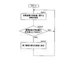
- FIG. 4 is a flowchart illustrating the processing of the control unit 20 of the individual ECU 2.
- the control unit 20 of the individual ECU 2 constantly performs the following processing in a start state (ignition switch is on) or a stop state (ignition switch is off) of the vehicle C, for example.
- the control unit 20 of the individual ECU 2 determines whether or not a signal (input signal) has been output from the switch 32 (S101).
- the control unit 20 determines whether or not a signal (input signal) is output from a switch 32 such as a door SW.
- the control unit 20 monitors a current, a signal, a pulse, or a voltage and duty applied through the harness connected to the harness connected to the switch 32 such as the door SW, and monitors a predetermined current value. When a voltage value, a signal waveform, or the like is detected, it is determined that a signal (input signal) is output from the switch 32.
- control unit 20 of the individual ECU 2 When no signal (input signal) is output from the switch 32 (S101: NO), the control unit 20 of the individual ECU 2 performs a loop process in order to execute the process of S101 again. That is, the control unit 20 of the individual ECU 2 continues to monitor the state of the switch 32.
- the control unit 20 of the individual ECU 2 When a signal (input signal) is output from the switch 32 (S101: YES), the control unit 20 of the individual ECU 2 starts acquiring the input signal and deriving the count value (S102). When a signal (input signal) is output from the switch 32, the control unit 20 of the individual ECU 2 starts acquiring the input signal. Further, the control unit 20 measures (derives) the count value by measuring the number of times that the switch 32 included in the input signal indicates on, etc., based on the input signal that has started acquisition, based on a predetermined sampling timing. Start.
- the initial value of the count value is set to 0, and the control unit 20 of the individual ECU 2 sets the count value by one according to the number of times of indicating on detected based on the sampling timing or each time chattering occurs. Increment processing that increases in increments may be performed.
- the control unit 20 of the individual ECU 2 determines whether or not the measured count value has reached the first threshold value (S103). When the count value has not reached the first threshold value (S103: NO), the control unit 20 of the individual ECU 2 determines whether or not the output of the signal (input signal) from the switch 32 is continuous (S1031). .. The control unit 20 of the individual ECU 2 determines, for example, whether or not the output of the signal (input signal) from the switch 32 is continuous based on the current or voltage of the wire harness connecting the switch 32 and the own ECU.
- the control unit 20 of the individual ECU 2 performs the loop processing again in order to make the processing of S103 a matter. That is, the control unit 20 continuously measures (derives) the count value while the signal (input signal) from the switch 32 is being output.
- the control unit 20 of the individual ECU 2 When the output of the signal (input signal) from the switch 32 is not continued (S1031: NO), that is, when the output of the signal is completed, the control unit 20 of the individual ECU 2 has to re-process the S101. , Perform loop processing. That is, the control unit 20 determines that the input signal acquired this time is not a regular signal output from the switch 32 but an erroneous signal generated by noise or the like, and the input is output from the switch 32 again. In order to determine the presence or absence of a signal, a process of monitoring the switch 32 is performed. In performing the loop process for performing the process S101, the control unit 20 of the individual ECU 2 may perform a process of returning the count value increased by the increment process to 0, which is the initial value.
- the signal that ends without the count value reaching the first threshold value is an erroneous signal generated by noise or the like. Therefore, by using the first threshold value as the number of times of the first digital filter, the erroneous signal causes the integrated ECU 6 and the in-vehicle device. It is possible to prevent unnecessary processing from being executed in step 3 and unnecessary power consumption.
- the control unit 20 of the individual ECU 2 When the count value reaches the first threshold value (S103: YES), the control unit 20 of the individual ECU 2 outputs the first signal (S104). When the count value reaches the first threshold value, the control unit 20 of the individual ECU 2 outputs a first signal for transitioning the integrated ECU to the activated state to the integrated ECU and other individual ECUs 2. The control ECU and the other individual ECU 2 that have received the first signal transition (return) from the stopped state or the standby state to the started state.
- the control unit 20 of the individual ECU 2 determines whether or not the count value has reached the second threshold value (S105). When the count value has not reached the second threshold value (S105: NO), the control unit 20 of the individual ECU 2 determines whether or not the output of the signal (input signal) from the switch 32 is continued as in S1031. Judgment (S1051).
- the control unit 20 of the individual ECU 2 performs the loop processing again in order to make the processing of S105 a matter. That is, the control unit 20 continuously measures (derives) the count value while the signal (input signal) from the switch 32 is being output.
- the control unit 20 of the individual ECU 2 When the output of the signal (input signal) from the switch 32 is not continued (S1051: NO), that is, when the output of the signal is completed, the control unit 20 of the individual ECU 2 increases the value of the first threshold value. (S1052).
- the control unit 20 determines that the input signal acquired this time is not a regular signal output from the switch 32 but an erroneous signal generated by, for example, noise, and sets the value of the first threshold value to, for example, one. , Perform processing that increases by a predetermined number. After executing S1052, the control unit 20 of the individual ECU 2 performs a loop process to execute the process of S101 again.
- a signal that ends without reaching the second threshold while the count value reaches the first threshold is an erroneous signal generated by noise or the like. Therefore, by using the second threshold as the number of times of the second digital filter, the erroneous signal is obtained. Therefore, it is possible to prevent the in-vehicle device 3 from executing unnecessary processing and unnecessarily consuming electric power.
- the control unit 20 of the individual ECU 2 outputs the first signal for activating the integrated ECU 6 or the like even if an erroneous signal due to noise or the like is input next time. By delaying the time point, it is possible to prevent the integrated ECU 6 and the like from being unnecessarily activated due to the erroneous signal, and to suppress an increase in power consumption.
- the control unit 20 of the individual ECU 2 When the count value reaches the second threshold value (S105: YES), the control unit 20 of the individual ECU 2 reduces the value of the first threshold value (S106) and outputs the second signal (S107).
- the second signal is output after the value of the first threshold value is reduced, but the present invention is not limited to this.
- the control unit 20 of the individual ECU 2 may reduce the value of the first threshold value after outputting the second signal.
- the control unit 20 of the individual ECU 2 may generate a sub-process to process the decrease of the value of the first threshold value and the output of the second signal in parallel.
- the control unit 20 of the individual ECU 2 determines that the acquired input signal is a normal signal output from the switch 32, and sets the first threshold value. , For example, one, etc., is processed to decrease by a predetermined number.
- the count value reaches the second threshold value in this way, it is highly probable that the vehicle C is placed in an operating environment in which the frequency of occurrence of erroneous signals due to noise or the like is low. Therefore, by reducing the first threshold value, in the next input signal, the first signal is output to the integrated ECU 6 or the like at an early stage to start the integrated ECU 6 or the like, and the actuator 30 corresponding to the switch 32 that outputs the input signal is provided. The responsiveness can be improved.
- the integrated ECU 6 that has acquired (received) the second signal output by the control unit 20 of the individual ECU 2 outputs the control signal to the other individual ECU 2 that is directly connected to the actuator 30 corresponding to the switch 32 that outputs the input signal. do.
- the other individual ECU 2 drives the actuator 30 by generating and outputting a drive signal for driving the actuator 30 based on the control signal from the integrated ECU 6.
- the control unit 20 of the individual ECU 2 may directly output the generated second signal to another individual ECU 2 directly connected to the actuator 30 corresponding to the switch 32 that outputs the input signal.
- the other individual ECU 2 that has acquired (received) the second signal may drive the actuator 30 by generating and outputting a drive signal based on the second signal.
- the control unit 20 of the individual ECU 2 increases the first threshold value by the processing of S1052, but the present invention is not limited to this.
- the control unit 20 of the individual ECU 2 has a first threshold value at the present time even when the process of S1052 should be executed, that is, even when the output of the signal (input signal) from the switch 32 is not continued (S1051: NO). If the value of is equal to a predetermined upper limit value, or if the upper limit value is exceeded by increasing the first threshold value at the present time, the first threshold value may not be increased and may be fixed.
- the upper limit value of the first threshold value is, for example, a value determined in order to secure the start waiting time (WakeUp waiting time) in relation to the second threshold value.
- the upper limit value of the first threshold value may be determined based on the ratio with the second threshold value, such as 80% of the second threshold value.
- the control unit 20 of the individual ECU 2 fixes the first threshold value because the value of the first threshold value at the present time reaches the upper limit value, the operating environment in which the vehicle C is placed is more likely to generate an erroneous signal than noise. It may be determined that the value is high, and information related to the determination may be output (transmitted) to the external server 100 via an HMI device such as a display or an external communication device 1. By outputting (transmitting) the information related to the determination to the HMI device or the external server 100, an erroneous signal is generated from noise in the operating environment in which the vehicle C (own vehicle) is placed to the operator of the vehicle C or the like. It is possible to notify that the frequency is high.
- FIG. 5 is a flowchart illustrating the processing of the control unit 20 of the individual ECU 2 according to the second embodiment (initialization of the first threshold value).
- the control unit 20 of the individual ECU 2 constantly performs the following processing in a start state (ignition switch is on) or a stop state (ignition switch is off) of the vehicle C, for example.
- the control unit 20 of the individual ECU 2 may perform the series of processes when the signal (input signal) is not output from the switch 32 in performing the series of processes of the present embodiment. That is, the control unit 20 determines whether or not a signal (input signal) is output from the switch 32 as in the process S101 of the first embodiment, and if the signal (input signal) is not output from the switch 32, the control unit 20 is the first. 1
- the process related to the initialization of the threshold value may be performed.
- the control unit 20 of the individual ECU 2 acquires information regarding the remaining capacity of the power storage device 5 (S201).
- the control unit 20 acquires information on the remaining capacity (SOC: statement of charge) of the power storage device 5 by communicating with the power storage device 5 or a drive ECU or the like connected to the power storage device 5.
- the control unit 20 of the individual ECU 2 may acquire information on the remaining capacity of the power storage device 5 by detecting the voltage of the power line connecting the own ECU and the power storage device 5.
- the control unit 20 of the individual ECU 2 determines whether or not the remaining capacity of the power storage device 5 is equal to or greater than a predetermined value (S202).
- the control unit 20 determines whether or not the remaining capacity of the power storage device 5 is equal to or more than a predetermined value, for example, based on the full capacity of the power storage device 5 and, for example, 85% of the full capacity as a predetermined value.
- the control unit 20 of the individual ECU 2 sets the value of the first threshold value to the initial value (S203).
- the initial value of the first threshold value is stored in the storage unit 21, and when the remaining capacity is equal to or larger than a predetermined value, the control unit 20 sets the value of the first threshold value at the present time to the initial value.
- the control unit 20 After executing S203, the control unit 20 performs loop processing again in order to make the processing of S201 a matter.
- the initialization process for returning the first threshold value to the initial value is performed when the remaining capacity of the power storage device 5 is equal to or greater than a predetermined value. Therefore, it is possible to efficiently prevent the so-called dead battery from occurring due to insufficient remaining capacity of the power storage device 5.
- the loop processing is performed again to make the processing of S201 a matter.
- the control unit 20 maintains the value without changing the value of the first threshold value at the present time, and performs loop processing again to make the processing of S201 a matter.
- the first threshold value is increased or decreased by processing based on the count value, and the generation of an erroneous signal due to noise or the like that causes the increase or decrease is affected by the operating environment of the vehicle C (own vehicle). Is assumed. Therefore, for example, when the vehicle state information such as the remaining capacity of the power storage device 5 satisfies a predetermined condition, the first signal is output by performing initialization processing and returning the first threshold value to a predetermined initial value. It is possible to constantly optimize the timing of the operation and stabilize the control. By determining the predetermined conditions based on the remaining capacity of the power storage device 5, it is possible to efficiently prevent a situation in which the remaining capacity of the power storage device 5 is insufficient while improving the responsiveness of the actuator 30. ..
- External server 1 External communication device 11 Antenna 2 Individual ECU (in-vehicle ECU) 20 Control unit 21 Storage unit 211 Recording medium 22 Input / output I / F (communication unit) 23 In-vehicle communication unit (communication unit) 231 Ethernet communication unit 232 CAN communication unit 3 In-vehicle device 30 Actuator (door opening / closing device) 31 Sensor 32 Switch (door SW) 33 Drive ECU 4 In-vehicle network 41 Communication line 411 Ethernet cable 412 CAN bus 5 Power storage device 6 Integrated ECU (vehicle control device)
Landscapes
- Engineering & Computer Science (AREA)
- Mechanical Engineering (AREA)
- Lock And Its Accessories (AREA)
- Small-Scale Networks (AREA)
Priority Applications (2)
| Application Number | Priority Date | Filing Date | Title |
|---|---|---|---|
| CN202180013598.6A CN115066869B (zh) | 2020-02-20 | 2021-02-04 | 车载ecu、程序以及信息处理方法 |
| US17/904,067 US12145516B2 (en) | 2020-02-20 | 2021-02-04 | Onboard ECU, program, and information processing method |
Applications Claiming Priority (2)
| Application Number | Priority Date | Filing Date | Title |
|---|---|---|---|
| JP2020-027383 | 2020-02-20 | ||
| JP2020027383A JP7310642B2 (ja) | 2020-02-20 | 2020-02-20 | 車載ecu、プログラム及び情報処理方法 |
Publications (1)
| Publication Number | Publication Date |
|---|---|
| WO2021166658A1 true WO2021166658A1 (ja) | 2021-08-26 |
Family
ID=77391966
Family Applications (1)
| Application Number | Title | Priority Date | Filing Date |
|---|---|---|---|
| PCT/JP2021/004075 Ceased WO2021166658A1 (ja) | 2020-02-20 | 2021-02-04 | 車載ecu、プログラム及び情報処理方法 |
Country Status (4)
| Country | Link |
|---|---|
| US (1) | US12145516B2 (https=) |
| JP (1) | JP7310642B2 (https=) |
| CN (1) | CN115066869B (https=) |
| WO (1) | WO2021166658A1 (https=) |
Families Citing this family (4)
| Publication number | Priority date | Publication date | Assignee | Title |
|---|---|---|---|---|
| CN116634531B (zh) * | 2022-02-10 | 2025-12-09 | 深圳引望智能技术有限公司 | 一种休眠唤醒方法、系统及装置 |
| JP7562594B2 (ja) * | 2022-03-31 | 2024-10-07 | 本田技研工業株式会社 | 車両通信システム、車両通信方法、および制御装置 |
| JP7732385B2 (ja) * | 2022-04-04 | 2025-09-02 | 株式会社オートネットワーク技術研究所 | 車載装置、車載システム、制御方法及びコンピュータプログラム |
| JP2026019256A (ja) * | 2024-07-26 | 2026-02-05 | 株式会社オートネットワーク技術研究所 | 車載用管理装置、及び車載システム |
Citations (3)
| Publication number | Priority date | Publication date | Assignee | Title |
|---|---|---|---|---|
| JP2005280374A (ja) * | 2004-03-26 | 2005-10-13 | Pioneer Electronic Corp | 車載機器制御装置 |
| JP2011192231A (ja) * | 2010-03-17 | 2011-09-29 | Aisin Aw Co Ltd | 車載入力装置及び車載入力装置用入力プログラム |
| JP2012132722A (ja) * | 2010-12-20 | 2012-07-12 | Stanley Electric Co Ltd | ロータリエンコーダの信号処理方法 |
Family Cites Families (26)
| Publication number | Priority date | Publication date | Assignee | Title |
|---|---|---|---|---|
| JP2733961B2 (ja) * | 1988-06-13 | 1998-03-30 | 富士ゼロックス株式会社 | 手駆動型複写装置 |
| JP2928651B2 (ja) * | 1991-03-19 | 1999-08-03 | 株式会社日立製作所 | 通信機能を備えた制御装置 |
| KR100302384B1 (ko) * | 1999-07-01 | 2001-09-22 | 김오영 | 자동차 전기장치의 디지털 통합 제어장치 및 방법 |
| JP4640309B2 (ja) * | 2006-10-03 | 2011-03-02 | 株式会社デンソー | 車載電子機器の制御システム |
| JP2009190517A (ja) * | 2008-02-13 | 2009-08-27 | Toyota Motor Corp | 車両挙動制御装置 |
| JP2010028356A (ja) * | 2008-07-17 | 2010-02-04 | Mitsubishi Fuso Truck & Bus Corp | 車載ネットワークの通信管理装置 |
| US8570147B2 (en) * | 2010-05-26 | 2013-10-29 | Lear Corporation | Debounce strategy for validating switch actuation |
| JP2012086823A (ja) * | 2010-09-22 | 2012-05-10 | Autonetworks Technologies Ltd | 侵入検知装置及び車載制御装置 |
| JP5951195B2 (ja) * | 2011-06-28 | 2016-07-13 | 株式会社小糸製作所 | 車両のランプ制御装置 |
| WO2013084665A1 (ja) * | 2011-12-09 | 2013-06-13 | 本田技研工業株式会社 | 電力制御装置 |
| JP5545321B2 (ja) * | 2012-06-12 | 2014-07-09 | トヨタ自動車株式会社 | スマート通信システム |
| JP5752668B2 (ja) * | 2012-11-16 | 2015-07-22 | 日信工業株式会社 | 車両用ブレーキ液圧制御装置 |
| JP2014125763A (ja) * | 2012-12-26 | 2014-07-07 | Smk Corp | 車両用制御装置 |
| JP6099129B2 (ja) * | 2013-01-21 | 2017-03-22 | オムロンオートモーティブエレクトロニクス株式会社 | 開閉体制御装置 |
| JP6286191B2 (ja) * | 2013-11-25 | 2018-02-28 | クラリオン株式会社 | 車載通信装置及びその制御方法 |
| US9865413B2 (en) * | 2015-04-10 | 2018-01-09 | Honda Motor Co., Ltd. | Vehicle control device |
| KR101775819B1 (ko) * | 2016-03-02 | 2017-09-11 | 원우엔지니어링주식회사 | 접점 지연을 보정한 제로 크로싱 스위치 및 그 동작 방법 |
| US10005448B2 (en) * | 2016-03-22 | 2018-06-26 | Ford Global Technologies, Llc | Load based engine start-stop control |
| JP2017224926A (ja) | 2016-06-14 | 2017-12-21 | 株式会社デンソー | チャタリング除去回路 |
| JP2017228033A (ja) * | 2016-06-21 | 2017-12-28 | 株式会社オートネットワーク技術研究所 | 車載記憶装置、車両情報記憶方法及びプログラム |
| CN106043712B (zh) * | 2016-06-23 | 2023-12-08 | 零度智控(北京)智能科技有限公司 | 无人机、无人机开机方法 |
| JP6665728B2 (ja) * | 2016-08-05 | 2020-03-13 | 株式会社オートネットワーク技術研究所 | 車載更新装置、車載更新システム及び通信装置の更新方法 |
| KR101883934B1 (ko) * | 2016-10-14 | 2018-08-01 | 콘티넨탈 오토모티브 시스템 주식회사 | 차량용 카드형 스마트키 및 그 제어 방법 |
| JP6642393B2 (ja) * | 2016-11-28 | 2020-02-05 | 株式会社オートネットワーク技術研究所 | 車載更新システム |
| CN109118693A (zh) * | 2018-08-18 | 2019-01-01 | 北京旺马科技有限公司 | 一种车辆监控方法、装置、系统及存储介质 |
| CN110805367A (zh) * | 2019-11-12 | 2020-02-18 | 合肥长安汽车有限公司 | 一种带有行车保护的行李箱开启控制方法 |
-
2020
- 2020-02-20 JP JP2020027383A patent/JP7310642B2/ja active Active
-
2021
- 2021-02-04 CN CN202180013598.6A patent/CN115066869B/zh active Active
- 2021-02-04 WO PCT/JP2021/004075 patent/WO2021166658A1/ja not_active Ceased
- 2021-02-04 US US17/904,067 patent/US12145516B2/en active Active
Patent Citations (3)
| Publication number | Priority date | Publication date | Assignee | Title |
|---|---|---|---|---|
| JP2005280374A (ja) * | 2004-03-26 | 2005-10-13 | Pioneer Electronic Corp | 車載機器制御装置 |
| JP2011192231A (ja) * | 2010-03-17 | 2011-09-29 | Aisin Aw Co Ltd | 車載入力装置及び車載入力装置用入力プログラム |
| JP2012132722A (ja) * | 2010-12-20 | 2012-07-12 | Stanley Electric Co Ltd | ロータリエンコーダの信号処理方法 |
Also Published As
| Publication number | Publication date |
|---|---|
| US12145516B2 (en) | 2024-11-19 |
| JP2021132336A (ja) | 2021-09-09 |
| US20230089480A1 (en) | 2023-03-23 |
| CN115066869A (zh) | 2022-09-16 |
| CN115066869B (zh) | 2024-07-02 |
| JP7310642B2 (ja) | 2023-07-19 |
Similar Documents
| Publication | Publication Date | Title |
|---|---|---|
| WO2021166658A1 (ja) | 車載ecu、プログラム及び情報処理方法 | |
| US9112721B2 (en) | System and methods for enabling a controller area network (CAN) device to operate in different power modes based upon the payload of a wake-up message | |
| US8081643B2 (en) | Relay connection unit | |
| KR20190000514A (ko) | 차량 네트워크에서 진단 오류 방지를 위한 방법 및 장치 | |
| JP2015199444A (ja) | 電子制御装置 | |
| US12565145B2 (en) | In-vehicle apparatus, information processing method, and program | |
| JP5601357B2 (ja) | 電子制御装置 | |
| WO2016111213A1 (ja) | 車載中継装置及び中継方法 | |
| US20220182258A1 (en) | In-vehicle network system | |
| CN117480761A (zh) | 中继装置、中继系统、中继方法及计算机程序 | |
| JP2010245935A (ja) | ゲートウェイ装置、スレーブ装置、及びネットワークシステム | |
| CN116080401A (zh) | 动态可重新配置的电池管理架构 | |
| JP5286659B2 (ja) | 車載装置中継システム、車載装置中継方法及び中継装置 | |
| JPWO2017018179A1 (ja) | 電子制御装置 | |
| JP2013098916A (ja) | 中継システム、及び、当該中継システムを構成する中継装置 | |
| CN121311390A (zh) | 车辆服务管理装置、车辆服务管理方法及车辆服务管理程序 | |
| CN114629731B (zh) | 车载系统、车载系统控制方法以及非暂时性记录介质 | |
| JP7581932B2 (ja) | 車載装置、通信速度の制御方法、及びプログラム | |
| JP7729059B2 (ja) | 車載管理装置および管理方法 | |
| WO2014203501A1 (ja) | 電子制御装置 | |
| JP6402452B2 (ja) | ゲートウェイ装置 | |
| WO2025263403A1 (ja) | 車載装置、車載システム、制御方法、およびコンピュータプログラム | |
| JP5949538B2 (ja) | 中継装置、及び通信システム並びに通信方法 | |
| CN121325809A (zh) | 一种车辆休眠控制方法、装置、车辆及存储介质 | |
| WO2024127949A1 (ja) | 車載装置、起動制御方法および起動制御プログラム |
Legal Events
| Date | Code | Title | Description |
|---|---|---|---|
| 121 | Ep: the epo has been informed by wipo that ep was designated in this application |
Ref document number: 21756403 Country of ref document: EP Kind code of ref document: A1 |
|
| NENP | Non-entry into the national phase |
Ref country code: DE |
|
| 122 | Ep: pct application non-entry in european phase |
Ref document number: 21756403 Country of ref document: EP Kind code of ref document: A1 |