WO2021153134A1 - 作業機 - Google Patents
作業機 Download PDFInfo
- Publication number
- WO2021153134A1 WO2021153134A1 PCT/JP2020/048842 JP2020048842W WO2021153134A1 WO 2021153134 A1 WO2021153134 A1 WO 2021153134A1 JP 2020048842 W JP2020048842 W JP 2020048842W WO 2021153134 A1 WO2021153134 A1 WO 2021153134A1
- Authority
- WO
- WIPO (PCT)
- Prior art keywords
- rotating shaft
- axial direction
- housing
- fan
- stator
- Prior art date
- Legal status (The legal status is an assumption and is not a legal conclusion. Google has not performed a legal analysis and makes no representation as to the accuracy of the status listed.)
- Ceased
Links
Images


Classifications
-
- F—MECHANICAL ENGINEERING; LIGHTING; HEATING; WEAPONS; BLASTING
- F21—LIGHTING
- F21V—FUNCTIONAL FEATURES OR DETAILS OF LIGHTING DEVICES OR SYSTEMS THEREOF; STRUCTURAL COMBINATIONS OF LIGHTING DEVICES WITH OTHER ARTICLES, NOT OTHERWISE PROVIDED FOR
- F21V33/00—Structural combinations of lighting devices with other articles, not otherwise provided for
- F21V33/008—Leisure, hobby or sport articles, e.g. toys, games or first-aid kits; Hand tools; Toolboxes
- F21V33/0084—Hand tools; Toolboxes
-
- B—PERFORMING OPERATIONS; TRANSPORTING
- B27—WORKING OR PRESERVING WOOD OR SIMILAR MATERIAL; NAILING OR STAPLING MACHINES IN GENERAL
- B27C—PLANING, DRILLING, MILLING, TURNING OR UNIVERSAL MACHINES FOR WOOD OR SIMILAR MATERIAL
- B27C5/00—Machines designed for producing special profiles or shaped work, e.g. by rotary cutters; Equipment therefor
- B27C5/10—Portable hand-operated wood-milling machines; Routers
-
- B—PERFORMING OPERATIONS; TRANSPORTING
- B25—HAND TOOLS; PORTABLE POWER-DRIVEN TOOLS; MANIPULATORS
- B25F—COMBINATION OR MULTI-PURPOSE TOOLS NOT OTHERWISE PROVIDED FOR; DETAILS OR COMPONENTS OF PORTABLE POWER-DRIVEN TOOLS NOT PARTICULARLY RELATED TO THE OPERATIONS PERFORMED AND NOT OTHERWISE PROVIDED FOR
- B25F5/00—Details or components of portable power-driven tools not particularly related to the operations performed and not otherwise provided for
- B25F5/008—Cooling means
-
- B—PERFORMING OPERATIONS; TRANSPORTING
- B25—HAND TOOLS; PORTABLE POWER-DRIVEN TOOLS; MANIPULATORS
- B25F—COMBINATION OR MULTI-PURPOSE TOOLS NOT OTHERWISE PROVIDED FOR; DETAILS OR COMPONENTS OF PORTABLE POWER-DRIVEN TOOLS NOT PARTICULARLY RELATED TO THE OPERATIONS PERFORMED AND NOT OTHERWISE PROVIDED FOR
- B25F5/00—Details or components of portable power-driven tools not particularly related to the operations performed and not otherwise provided for
- B25F5/02—Construction of casings, bodies or handles
- B25F5/021—Construction of casings, bodies or handles with guiding devices
Definitions
- the present invention relates to a working machine.
- Patent Document 1 discloses a router (working machine) that performs cutting work on a material to be cut by rotating a tip tool by driving a motor. Specifically, when the operator grasps the handle of the router and pushes the router downward, the tip tool comes into contact with the material to be cut and the cutting work is performed on the material to be cut. ..
- some routers are provided with a lighting unit that illuminates the periphery of the tip tool in order to improve workability during cutting.
- the lighting unit when the lighting unit is mounted on the router described in Patent Document 1, it is necessary to separately provide a member or the like for holding the lighting unit. Therefore, there is a possibility that the number of parts may increase. Therefore, when mounting the lighting unit on the router, it is desirable to have a structure that can illuminate the surroundings of the tip tool while suppressing an increase in the number of parts. Further, when the lighting unit is mounted, it is desirable to suppress the deterioration of the assembling property.
- One or more embodiments of the present invention include a rotary shaft, a rotor configured to be integrally rotatable on the rotary shaft, and a stator arranged on the radial outer side of the rotor.
- a fan provided on the rotating shaft and arranged on one side of the rotating shaft in the axial direction with respect to the rotor and the stator, a housing for accommodating the motor, and one end portion of the rotating shaft in the axial direction.
- One or more embodiments of the present invention include a rotary shaft, a rotor configured to be integrally rotatable on the rotary shaft, and a stator arranged on the radial outer side of the rotor.
- the tip tool is provided, an illumination unit including a light source that irradiates the emitted light toward the periphery of the tip tool, and the stator provided on one side of the rotation axis in the axial direction. It is a working machine provided with a holding member that holds the illumination unit and restricts the movement of the rotating shaft in the stator to one side in the axial direction.
- the housing includes a first housing that houses the motor, and a second housing that is provided on one side of the rotating shaft in the axial direction with respect to the first housing.
- the holding member is a working machine sandwiched between the first housing and the second housing in the axial direction of the rotating shaft.
- the second housing is formed with an engaging portion engaged with the holding member, and the rotation of the holding member in the circumferential direction of the rotating shaft is the same. It is a working machine regulated by the engaging part.
- the holding member extends from a base portion arranged between the rotor, the stator, and the fan, and from the base portion to one side in the axial direction of the rotating shaft. It is a working machine including an extension portion and the lighting portion, which is held at the tip end portion of the extension portion.
- the holding member extends from a base located between the rotor, the stator, and the fan, and from the base to one side of the rotating shaft in the axial direction.
- the illuminating portion is held at the base end portion of the extending portion, and the extending portion transmits the light emitted by the light source to transmit the light. Is a working machine in which light is emitted from the tip of the extending portion toward the periphery of the tip tool.
- a groove portion is formed in the base portion so as to be open to the other side in the axial direction of the rotation shaft, and wiring connected to the illumination portion is provided in the groove portion. It is a work machine that has been arranged.
- the holding member holds a pair of the lighting units, and a wiring connecting the pair of the lighting units is arranged in the groove. Is.
- a split housing is provided on the other side of the rotating shaft in the axial direction with respect to the housing, and the split housing is provided with respect to the axial direction of the rotating shaft. It is a work machine that is configured so that it can be divided in orthogonal directions.
- One or more embodiments of the present invention is a working machine provided with a control unit for controlling lighting and extinguishing of the lighting unit in the divided housing.
- One or more embodiments of the present invention is a working machine in which a battery for supplying electric power to the lighting unit is detachably provided in the divided housing.
- One or more embodiments of the present invention include a rotating shaft, a rotor configured to be integrally rotatable on the rotating shaft, and a stator arranged radially outside the rotor.
- a fan provided on the rotating shaft and arranged on one side of the rotating shaft in the axial direction with respect to the rotor and the stator, a housing for accommodating the motor, and one end portion of the rotating shaft in the axial direction.
- the holding member comprises a tip tool, a lighting unit including a light source that irradiates the emitted light toward the periphery of the tip tool, and a holding member that holds the lighting unit.
- a base portion arranged between the rotor and the stator and the fan, and a base portion extending from the base portion to one side in the axial direction of the rotation shaft to hold the illumination portion and light emitted by the light source. It is configured to include an extending portion that is transmitted and irradiates the light from the tip portion toward the periphery of the tip tool, and the tip portion of the extending portion is a shaft of the rotating shaft rather than the fan. It is a work machine located on one side of the direction.
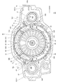
- FIG. 5 is an exploded perspective view of the router main body of the router shown in FIG. 1 as viewed diagonally from the front to the right. It is sectional drawing (4-4 line sectional drawing of FIG. 1) which looked at the router shown in FIG. 1 from the lower side of the router main body. It is sectional drawing (5-5 line sectional drawing of FIG. 4) seen from the front side which shows the inside of the router main body shown in FIG. It is sectional drawing (6-6 line sectional drawing of FIG. 4) which showed the inside of the router main body shown in FIG. 4 from the front side which shows the position of the illumination hole.
- FIG. 5 is a plan sectional view (cross-sectional view taken along line 7-7 of FIG. 5) of the motor housed in the motor housing portion shown in FIG. 5 as viewed from above at the position of the lower end portion of the motor.
- FIG. 5 is a plan sectional view (FIG. 8-8 sectional view of FIG. 5) of the holding ring shown in FIG. 5 in a state of being housed in the end bracket, as viewed from above at the position of the upper end portion of the holding ring.
- (A) is an enlarged perspective view showing the holding ring shown in FIG. 3, and
- (B) is a front view of the holding ring of (A) seen from the front side.
- FIG. 8 It is a top view which shows the state which the illuminating part was held by the holding ring shown in FIG. 8 in an enlarged manner.
- A is a cross-sectional view (cross-sectional view taken along the line 11A-11A of FIG. 10) showing the ring base of the holding ring shown in FIG. 10 at the position of the reinforcing rib
- B is the holding ring shown in FIG.
- It is a cross-sectional view (11B-11B line cross-sectional view of FIG. 10) which shows around the holding column.
- C) is a cross-sectional view (11C-11C line cross-sectional view of FIG. 11B) showing a vertical intermediate portion of the holding column shown in (B), and (D) is (B).
- FIG. 11B It is a cross-sectional view (11D-11D line cross-sectional view of FIG. 11B) seen from the upper side which shows the lower end part of the holding column shown by).
- (A) is a cross-sectional view seen from the front side showing a modified example of the holding ring when the fan shown in FIG. 6 is a centrifugal fan
- (B) is a right side showing the fan and the holding ring of (A).
- 11 is a cross-sectional view corresponding to FIG. 11B showing a modified example of the holding ring when the vertical position of the illumination unit shown in FIG. 11B is changed.
- the router 10 as a "working machine" according to the present embodiment will be described with reference to the drawings.
- the arrows UP, FR, and RH appropriately shown in the drawings indicate the upper side, the front side, and the right side of the router 10, respectively. Then, in the following description, when the description is made using the vertical, front-back, and left-right directions, unless otherwise specified, the vertical direction, the front-back direction, and the left-right direction of the router 10 are indicated.
- the router 10 is mounted on the upper side of the material to be cut and is configured as a tool for cutting the material to be cut. As shown in FIGS. 1 and 2, the router 10 includes a base 20, a router main body 30, a pair of lighting units 70L and 70R (see FIG. 8), a battery holder 80 as a “split housing”, and “ A battery 85 as a "battery” and a control unit 90 (see FIG. 5) are included.
- each configuration of the router 10 will be described.
- the base 20 constitutes a lower end portion of the router 10 and is formed in a substantially disk shape with the vertical direction as the plate thickness direction.
- An insertion portion 20A is formed through the substantially central portion of the base 20 in the vertical direction.
- a pair of columns 21 are provided at both ends of the base 20 in the left-right direction, and the columns 21 are formed in a substantially cylindrical shape with the vertical direction as the axial direction.
- the lower end of the column 21 is fixed to the base 20, and the column 21 extends upward from the base 20.
- the base 20 is provided with bolts 22 extending in the vertical direction on the rear side of the column 21 on the left side.
- the lower end of the bolt 22 is fixed to the base 20, and the bolt 22 extends upward from the base 20.
- a nut 23 (see FIG. 3) is screwed to the upper end of the bolt 22.
- the router main body 30 includes a housing 31 constituting the outer shell of the router main body 30, a motor 40 housed inside the housing 31, and a "holding member".
- the holding ring 60 and a pair of left and right handles 50 attached to the housing 31 are included.
- the housing 31 includes an end bracket 32 as a "second housing” forming the lower part of the housing 31 and a motor housing 33 as a "first housing” forming the upper part of the housing 31.
- the end bracket 32 is made of a metal material.
- the end bracket 32 is formed in a substantially rectangular parallelepiped box shape that is open upward and has a longitudinal direction in the left-right direction.
- the end bracket 32 has an integral structure and cannot be divided.
- a pair of connecting cylinders 32A are formed on both ends of the end bracket 32 in the left-right direction.
- the connecting cylinder portion 32A is formed in a substantially cylindrical shape with the vertical direction as the axial direction, and protrudes upward and downward from the bottom wall of the end bracket 32. Then, the column 21 described above is inserted into the connecting cylinder portion 32A so as to be relatively movable in the vertical direction.
- the fan accommodating portion 32B is formed in a substantially cylindrical shape and projects upward from the bottom wall of the end bracket 32.
- the end bracket 32 is formed with a substantially cylindrical support cylinder portion 32C inside the fan accommodating portion 32B in the radial direction.
- the support cylinder portion 32C is arranged coaxially with the fan accommodating portion 32B, and the inside of the support cylinder portion 32C penetrates in the vertical direction.
- a plurality of relief grooves 32D (see FIG.
- a plurality of exhaust holes 32E are formed between the fan accommodating portion 32B and the support cylinder portion 32C.
- the plurality of exhaust holes 32E are arranged side by side in the fan accommodating portion 32B along the circumferential direction.
- an illumination hole 32F is formed through in the vertical direction on the radial outer side of the fan accommodating portion 32B. There is.
- One illumination hole 32F is arranged diagonally to the right and rearward with respect to the axis AL of the support cylinder portion 32C, and the other illumination hole 32F is arranged obliquely rearward to the left with respect to the axis AL of the support cylinder portion 32C. There is.
- handle fixing portions 32G for fixing the handle 50 are formed at both ends of the end bracket 32 in the left-right direction.
- the handle fixing portion 32G is formed in a substantially columnar shape with the left-right direction as the axial direction, and projects outward from the end bracket 32 in the left-right direction.
- a cutout portion 32H (see cross section AA in FIG. 4) is formed on the outer peripheral portion of the handle fixing portion 32G on the right side, and the cutout portion 32H is open to the rear side and the upper side when viewed from the right side.
- a stopper portion 32J (see FIG. 4) projecting to the rear side is formed on the outer peripheral portion of the left end portion of the end bracket 32.
- the stopper portion 32J is formed in a substantially tubular shape in the vertical direction and the axial direction, and the bolt 22 described above inserts the inside of the stopper portion 32J. Then, the stopper portion 32J is in contact with the nut 23 provided at the upper end portion of the bolt 22 from below. As a result, the movement of the end bracket 32 (router main body 30) upward is restricted at the positions shown in FIGS. 1 and 2 (hereinafter, the position of the router main body 30 is referred to as an "initial position").
- the motor housing 33 is made of a resin material and is arranged adjacent to the upper side of the end bracket 32.
- the motor housing 33 is formed in a substantially rectangular box shape (cylindrical shape) that is open downward.
- the motor housing 33 is integrally formed, and cannot be divided in the front-rear direction or the left-right direction, for example. Further, the opening of the motor housing 33 is formed in a shape corresponding to the opening of the end bracket 32. Then, the motor housing 33 is fastened and fixed to the end bracket 32 so as to close the opening of the end bracket 32.
- a pair of left and right connecting shafts 35 are provided inside the motor housing 33 at positions corresponding to the columns 21 described above.
- the connecting shaft 35 is formed in a substantially columnar shape with the vertical direction as the axial direction, extends downward from the top wall of the motor housing 33, and is inserted into the column 21 so as to be relatively movable in the vertical direction.
- an urging spring 36 configured as a compression coil spring is extrapolated to the connecting shaft 35.
- the upper end of the urging spring 36 is locked to the top wall of the motor housing 33, and the lower end of the urging spring 36 is locked to the upper end of the column 21. (That is, the router body 30) is urged upward.
- the router main body 30 is held in the initial position.
- the router main body 30 is pushed downward against the urging force of the urging spring 36, so that the router main body 30 moves downward relative to the base 20.
- a motor accommodating portion 33A for accommodating the motor 40 is formed in the central portion in the left-right direction of the motor housing 33.
- the motor accommodating portion 33A is formed in a substantially bottomed cylindrical shape that is open downward, and is arranged coaxially with the fan accommodating portion 32B and the support cylinder portion 32C of the end bracket 32.
- Four guide ribs 33B extending in the vertical direction are formed on the side wall of the motor accommodating portion 33A.
- the guide ribs 33B project radially inward and outward from the side wall of the motor accommodating portion 33A, and the lower end portion of the guide rib 33B projects downward from the side wall of the motor accommodating portion 33A.
- one guide rib 33B is arranged diagonally to the left and rearward with respect to the axis AL of the motor accommodating portion 33A, and four guide ribs 33B are arranged every 90 degrees in the circumferential direction of the motor accommodating portion 33A. ing.
- a pair of front and rear right rotation restricting ribs 33C (see FIG. 7) extending in the vertical direction are formed at the right end of the inner peripheral surface of the motor accommodating portion 33A, and the pair of right front and rear rotation restricting ribs 33C are front and rear. They are arranged at predetermined intervals in the direction. Further, a pair of left side rotation restricting ribs 33D (see FIG. 7) extending in the vertical direction are formed at the left end portion of the inner peripheral surface of the motor accommodating portion 33A. Further, a pair of left and right axial regulation ribs 33E (see FIG. 5) are formed on the inner peripheral surface of the motor accommodating portion 33A.
- the axial regulation rib 33E extends from the top wall of the motor accommodating portion 33A to the vertical intermediate portion of the motor accommodating portion 33A.
- the right axial regulation rib 33E is arranged between the pair of right rotation regulation ribs 33C and connected to the pair of right rotation regulation ribs 33C.
- the left axial regulation rib 33E is arranged on the front side of the left rotation regulation rib 33D and is connected to the left rotation regulation rib 33D.
- the communication holes 33F are formed through the top wall of the motor accommodating portion 33A.
- the communication holes 33F are formed in a substantially fan shape in a plan view, and are arranged every 90 degrees in the circumferential direction of the motor accommodating portion 33A.
- a communication groove 33G open to the lower side is formed at the right end portion at the lower end portion of the motor housing 33, and the inside and the outside of the motor housing 33 are communicated by the communication groove 33G.
- the motor 40 is housed in the motor housing 33A of the motor housing 33.
- the motor 40 includes a rotating shaft 41 having an axial direction in the vertical direction, a substantially cylindrical rotor 42 fixed to the rotating shaft 41, and a substantially cylindrical stator 43 arranged radially outside the rotor 42. It is configured to include.
- the rotating shaft 41 is arranged coaxially with the motor accommodating portion 33A, and the lower end portion (one end portion on one side in the axial direction) of the rotating shaft 41 projects downward from the motor housing 33 to support the end bracket 32.
- the inside of the cylinder portion 32C is inserted. That is, the axis of the rotating shaft 41 coincides with the axis AL.
- the lower end of the rotating shaft 41 is rotatably supported by the bearing 34 of the end bracket 32, and the upper end of the rotating shaft 41 is rotatably supported by the bearing 37 fixed to the motor housing 33. .. Since the bearing 34 and the bearing 37 are held by the end bracket 32 and the motor housing 33, which have high rigidity because they are indivisible, the rotating shaft 41 can be supported with high accuracy.
- a tip tool 46 is attached to the lower end of the rotating shaft 41 via a collect chuck 45. As a result, the tip tool 46 is configured to insert the inside of the insertion portion 20A of the base 20 by pushing down the router main body 30 from the initial position.
- the stator 43 has a stator holder 44, and the stator holder 44 is formed in a substantially cylindrical shape.
- a stator coil (not shown) is wound around the stator holder 44, and the stator coil is connected to a motor substrate 40A provided at the upper end of the motor 40.
- a pair of left and right positioning ribs 44A are formed on the outer peripheral portion of the stator holder 44, and the positioning ribs 44A extend in the vertical direction.
- the guide ribs 33B of the motor housing 33 are arranged adjacent to the radial outer side of the stator holder 44 (see FIG. 7).
- the stator holder 44 (stator 43) is arranged coaxially with the rotating shaft 41.
- the right positioning rib 44A is inserted between the pair of right side rotation restricting ribs 33C in the motor housing 33, and the left side positioning rib 44A is arranged adjacent to the front side of the left side rotation restricting rib 33D of the motor housing 33. (See Fig. 7).
- the relative rotation of the stator 43 with respect to the motor housing 33 is regulated by the right side rotation restricting rib 33C, the left side rotation restricting rib 33D, and the positioning rib 44A.
- the positioning rib 44A is arranged adjacent to the lower side of the axial regulation rib 33E of the motor housing 33, and is arranged adjacent to the upper side of the holding ring 60 described later (see FIG. 5).
- the vertical movement of the stator 43 is restricted by the axial regulation rib 33E and the holding ring 60.
- a fan 47 is integrally rotatably provided at the lower end of the rotating shaft 41 under the rotor 42 and the stator 43. Specifically, the fan 47 is arranged on the upper side of the support cylinder portion 32C of the end bracket 32 and on the radial inner side of the upper portion of the fan accommodating portion 32B. Further, the upper portion of the fan 47 projects upward from the fan accommodating portion 32B.
- the fan 47 has a plurality of blades 47A. The blades 47A extend in the radial direction of the rotating shaft 41 and are arranged side by side in the rotating direction of the fan 47.
- the fan 47 is configured as a so-called axial flow fan, and when the fan 47 rotates, the air (cooling air) flowing in from the intake hole 80B described later cools the control unit 90, and then the control unit 90 is cooled.
- the motor 40 flows into the inside of the motor housing 33 from the upper opening of the motor housing 33, is rectified to the lower side of the fan 47, and flows out from the exhaust hole 32E to the lower side.
- the handle 50 is formed in a hollow substantially T-shape rotated by 90 degrees when viewed from the front.
- the handle 50 includes a substantially cylindrical mounting portion 50A whose axial direction is the left-right direction, and a grip portion 50B extending in the vertical direction from the lateral end portion in the left-right direction of the mounting portion 50A. It is configured.
- the handle 50 is divided into two in the left-right direction at the portion of the grip portion 50B, and is composed of two members.
- the handle 50 includes a handle body 51 that constitutes an inner portion in the left-right direction of the handle 50, and a handle cover 52 that forms an outer portion in the left-right direction of the handle 50.
- the handle fixing portion 32G of the end bracket 32 is inserted inside the mounting portion 50A, and the handle body 51 is fastened and fixed to the end bracket 32. Further, after the handle body 51 is fixed to the end bracket 32, the handle cover 52 is fastened and fixed to the handle body 51 with screws.
- the handle 50 on the right side is provided with a switch button 53 that can be pressed and operated at the upper part, and a trigger 54 that can be operated by pulling at the rear part. Further, inside the handle 50 on the right side, a switch circuit portion 55 that is operated by operating the switch button 53 and the trigger 54 is provided, and the switch circuit portion 55 is fixed to the handle main body 51.
- the switch circuit unit 55 has a switch (not shown) operated by a switch button 53 and a trigger 54. The switch is electrically connected to the control unit 90 described later, and is configured to output an output signal according to the operating state of the switch button 53 and the trigger 54 to the control unit 90 described later.
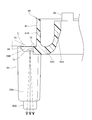
- the holding ring 60 is made of a transparent resin material having translucency.
- the holding ring 60 has a ring base 61 as a "base”.
- the ring base 61 is formed in a substantially ring shape (substantially cylindrical shape) with the vertical direction as the axial direction, and is formed in a substantially U shape open upward in a cross-sectional view seen from the circumferential direction. Has been done.
- the ring base 61 includes a substantially cylindrical inner cylinder 61A whose axial direction is the vertical direction, a cylindrical outer cylinder 61B arranged radially outside the inner cylinder 61A, and a lower end of the inner cylinder 61A. It is configured to include a bottom portion 61C that connects the portion and the lower end portion of the outer cylinder 61B. As a result, a guide groove 62 as a "groove portion" opened upward is formed inside the ring base 61.
- the ring base 61 is arranged inside the end bracket 32 on the outer side in the radial direction of the fan 47. Specifically, the bottom portion 61C of the ring base 61 is arranged adjacent to the upper side of the fan accommodating portion 32B of the end bracket 32, and the outer cylinder 61B of the ring base 61 is a part of the lower end portion of the motor housing 33. It is located adjacent to the lower side. As a result, the ring base 61 is sandwiched in the vertical direction by the end bracket 32 and the motor housing 33, and is fixed to both of them.
- the upper portion of the blade 47A of the fan 47 is arranged radially inside the lower portion of the inner cylinder 61A of the ring base 61.
- the air in the motor housing 33 is guided by the inner cylinder 61A of the holding ring 60 and flows to the fan 47 (blade 47A) side.
- a pair of left and right restricting portions 63 projecting upward are formed on the upper end surface of the inner cylinder 61A.
- the regulating portion 63 is arranged at a position corresponding to the positioning rib 44A of the stator 43, and the lower end of the positioning rib 44A is in contact with the upper end of the regulating portion 63 (see FIG. 5). As a result, the downward movement of the stator 43 is restricted by the holding ring 60.
- the guide recess 64 is formed in a concave shape that is open to the upper side, and is arranged at a position corresponding to the guide rib 33B of the motor housing 33. Then, the lower end portion of the guide rib 33B is inserted into the guide recess 64 (see FIGS. 5, 6, and 8). As a result, when the motor housing 33 is attached to the end bracket 32, the holding ring 60 is configured to guide the motor housing 33.
- the lower end portion of the guide rib 33B is configured to extend in the radial direction of the ring base 61 in the upper portion of the guide groove 62 of the holding ring 60. (See FIG. 8).
- the holding ring 60 has a holding pillar 65 as a pair of left and right "extending parts" for holding the lighting parts 70L and 70R described later.
- the holding column 65 is formed in a substantially rectangular columnar shape extending in the vertical direction. Further, the holding column 65 is arranged at a position corresponding to the illumination hole 32F of the end bracket 32 described above (see FIG. 8), and is arranged adjacent to the outer side in the radial direction of the ring base 61. Specifically, one holding column 65 is arranged diagonally to the right and rearward with respect to the axis AL of the rotating shaft 41 in a plan view, and the other holding column 65 is arranged diagonally rearward to the right with respect to the axis AL of the rotating shaft 41 in a plan view.
- the upper end of the holding column 65 is connected to the lower end of the outer cylinder 61B of the ring base 61, and the holding column 65 is integrally formed with the ring base 61. That is, the holding column 65 extends downward from the ring base 61. Specifically, the lower end of the holding column 65 is arranged below the fan 47. That is, the holding column 65 extends in the vertical direction on the radial outer side of the fan 47.
- the holding column 65 is tilted at approximately 45 degrees in a plan view, and the rear surface 65A of the holding column 65 is tilted to the rear side toward the right side in a plan view.
- the lighting accommodating portions 66 (FIGS. 11B and D) for accommodating the illumination portions 70L and 70R described later are accommodated. ) Is formed, and the illumination accommodating portion 66 is formed in a concave shape that is open to the rear side (specifically, in a direction orthogonal to the rear surface 65A). Further, a pair of wiring grooves 67 (see FIGS.
- the wiring grooves 67 extend in the vertical direction and are arranged side by side in the width direction of the holding columns 65.
- the upper end of the wiring groove 67 is open to the upper side, and the lower end of the wiring groove 67 communicates with the illumination accommodating portion 66.
- a lens portion 65B (in a broad sense, an element grasped as an "engaged portion") is formed at the lower end portion of the holding column 65.
- the lens portion 65B is formed in a substantially columnar shape with the vertical direction as the axial direction, and protrudes downward from the holding column 65. Then, the lens portion 65B is fitted in the illumination hole 32F of the end bracket 32. As a result, the lens portion 65B and the illumination hole 32F are engaged with each other around the axis AL, and the position of the holding ring 60 with respect to the end bracket 32 is determined.
- the ring base 61 is arranged coaxially with the rotating shaft 41.
- a pair of wiring slits 68L and 68R are formed in the outer cylinder 61B of the ring base 61 at positions corresponding to the pair of left and right holding columns 65.
- the pair of wiring slits 68L and 68R are formed through the outer cylinder 61B in the radial direction and are opened upward. As a result, the inside and the outside of the ring base 61 are communicated with each other by the wiring slits 68L and 68R.
- the reinforcing rib 69 is formed in a plate shape with the circumferential direction of the ring base 61 as the plate thickness direction, and is connected to the inner cylinder 61A, the bottom portion 61C, and the outer cylinder 61B.
- One reinforcing rib 69 is arranged at the rear end of the ring base 61, and four reinforcing ribs 69 are arranged at 90 degree intervals in the circumferential direction of the ring base 61.
- a wiring slit 69A is formed in the reinforcing rib 69.
- the wiring slit 69A is formed through the reinforcing rib 69 in the plate thickness direction and is open to the upper side.
- the lighting units 70L and 70R have a lighting substrate 71 and an LED 72 as a “light source”, respectively.
- the lighting substrate 71 is formed in a substantially rectangular plate shape with the vertical direction as the plate thickness direction, and is housed in the lighting accommodating portion 66 of the holding ring 60.
- the LED 72 is mounted on the lower surface of the lighting board 71 and is housed in the lighting housing portion 66 together with the lighting board 71.
- the LED 72 (illumination units 70L, 70R) is arranged below the fan 47.
- the LED 72 is configured to irradiate the emitted light downward. Specifically, the light emitted by the LED 72 passes through the lens portion 65B of the holding ring 60 and illuminates the lower side of the end bracket 32 from the illumination hole 32F of the end bracket 32. As a result, the light is used to illuminate the periphery of the tip tool 46. More specifically, the light emitted by the LED 72 is configured to illuminate the periphery of the tip tool 46 on the rear side of the tip tool 46 and on the outside in the left-right direction.
- two lead wires 73 as "wiring” extend from the lighting board 71, and the lead wire 73 is inside the wiring groove 67 of the holding column 65 on the left side in the holding ring 60. It is arranged in. Further, the lead wire 73 is inserted into the guide groove 62 of the ring base 61 from the left wiring slit 68L in the holding ring 60, is arranged in the rear portion of the guide groove 62, and is arranged from the right wiring slit 68R to the guide groove. It extends to the outside of 62.
- the lead wire 73 is inserted through the wiring slit 69A of the reinforcing rib 69 on the rear side, and extends from the wiring slit 68R on the right side to the outside of the guide groove 62. Further, in the arrangement state of the lead wire 73 into the guide groove 62, the lower end portion of the guide rib 33B of the motor housing 33 is arranged on the upper side of the lead wire 73, and the movement of the lead wire 73 to the upper side is restricted by the guide rib 33B. (See FIG. 8).
- one of the two lead wires 73 is arranged in the wiring groove 67 of one of the holding columns 65 on the right side, and is connected to the lighting board 71 of the lighting unit 70R on the right side.
- a lead wire 74 as "wiring” extends from the lighting board 71 of the lighting unit 70R on the right side, and the lead wire 74 is arranged in the other wiring groove 67 in the holding column 65 on the right side. ..
- the other lead wire 73 and the lead wire 74 are connected to the switch circuit portion 55 through the inside of the mounting portion 50A of the handle 50 on the right side.
- the lead wire 73 and the lead wire 74 are connected to the switch circuit portion 55 through the communication groove 33G of the motor housing 33 and the notch portion 32H of the handle fixing portion 32G in the end bracket 32.
- the battery holder 80 is provided on the upper side of the motor housing 33 and is formed in a substantially box shape open to the lower side.
- the battery holder 80 is divided into two in the front-rear direction. That is, the battery holder 80 includes a front holder 81 and a rear holder 82 that form a front portion of the battery holder 80, and the front holder 81 and the rear holder 82 are fastened to the motor housing 33. It is fixed.
- the battery holder 80 is formed with a battery mounting portion 80A for mounting the battery 85, which will be described later, and the battery mounting portion 80A is formed in a concave shape open to the upper side and the left side. Further, an intake hole 80B that functions as an inlet for an air flow generated by the rotation of the fan 47 is formed near the center of the battery holder 80 in the vertical direction. Specifically, an intake hole 80B is formed in the front side wall of the front holder 81 and the rear side wall of the rear holder 82. Further, the battery holder 80 is provided with a connector 83 (see FIG. 3), and the upper portion of the connector 83 is exposed inside the battery mounting portion 80A so as to be connectable to the battery 85 described later.
- Battery 85 is formed in a substantially rectangular parallelepiped. Then, the battery 85 is attached to the battery mounting portion 80A of the battery holder 80 from the left side.
- the battery 85 has a connector (not shown), and when the battery 85 is attached to the battery mounting portion 80A, the connector is connected to the connector 83 and power is supplied to the control unit 90 described later. ing. Further, the battery 85 has a pair of lock members 86, and the lock members 86 are provided on the front and rear side portions of the battery 85. When the battery 85 is mounted on the battery mounting portion 80A, the lock member 86 engages with the battery holder 80 to maintain the mounted state of the battery 85.
- control unit 90 As shown in FIG. 3, the control unit 90 is housed inside the battery holder 80 and fixed to the battery holder 80.
- the control unit 90 has a control board (not shown), and the motor 40 and the connector 83 described above are electrically connected to the control board.
- a lead wire (not shown) extending from the motor board 40A is connected to the control board through the communication hole 33F of the motor housing 33.
- a lead wire (not shown) extending from the control board is connected to the switch circuit unit 55, and the control unit 90 and the switch circuit unit 55 are electrically connected.
- the lead wire is arranged in the motor housing 33 on the radial outer side of the motor housing portion 33A, and in the communication groove 33G of the motor housing 33 and in the notch 32H of the handle fixing portion 32G in the end bracket 32. Is inserted and connected to the switch circuit unit 55. As a result, the control unit 90 and the lighting units 70L and 70R are electrically connected. Then, the control unit 90 is configured to turn on or off the LED 72 according to the on / off operation of the switch button 53. Further, the control unit 90 controls the operation of the motor 40 by operating the trigger 54 while the switch button 53 is on.
- the router 10 configured as described above includes lighting units 70L and 70R having an LED 72.
- the illumination units 70L and 70R are housed in the illumination accommodating unit 66 of the holding ring 60 and are held by the holding ring 60. Then, when the operator grips the grip portion 50B of the handle 50 and turns on the switch button 53, the power of the battery 85 is supplied to the LED 72 by the control unit 90, and the LED 72 emits light.
- the light emitted by the LED 72 passes through the lens portion 65B of the holding ring 60 and irradiates downward from the illumination hole 32F of the end bracket 32 to illuminate the periphery of the tip tool 46. Specifically, the lateral and rear portions of the tip tool 46 in the left-right direction are illuminated.
- the rotating shaft 41 of the motor 40 rotates together with the tip tool 46 under the control of the control unit 90.
- the router main body 30 moves downward relative to the base 20.
- the tip tool 46 comes into contact with the material to be cut, and the material to be cut is cut.
- the operator cuts the material to be cut while moving the router 10 to the rear side.
- the portion of the router 10 on the moving direction side of the tip tool 46 is illuminated by the LED 72.
- the visibility around the tip tool 46 can be improved during cutting. Therefore, the workability for the worker can be improved.
- a holding ring 60 for holding the illumination units 70L and 70R is provided below the stator 43 of the motor 40. Then, the regulating portion 63 of the holding ring 60 is arranged adjacent to the lower side of the positioning rib 44A of the stator 43 to restrict the movement of the stator 43 to the lower side. That is, the holding ring 60 has two functions, that is, a function of holding the illumination units 70L and 70R and a function of restricting the downward movement of the stator 43. In other words, the illumination units 70L and 70R can be held by utilizing the holding ring 60 that regulates the downward movement of the stator 43.
- the members for holding the illumination units 70L and 70R and the members for restricting the downward movement of the stator 43 can be used as a common member, and the illumination units 70L and 70R can be mounted on the router 10.
- the surroundings of the tip tool 46 can be illuminated by the illuminating units 70L and 70R while suppressing an increase in the number of parts.
- the upper portion of the fan 47 is arranged radially inside the lower portion of the ring base 61 in the holding ring 60.
- the air on the upper side of the fan 47 can be guided by the inner cylinder 61A of the ring base 61 and guided to the blade 47A side of the fan 47. Therefore, the air in the motor housing 33 can be efficiently guided to the fan 47 by utilizing the holding ring 60 that regulates the downward movement of the stator 43.
- the bottom portion 61C of the ring base 61 is arranged adjacent to the upper side of the fan accommodating portion 32B of the end bracket 32, and the outer cylinder 61B of the ring base 61 is located at the lower end portion of the motor housing 33. It is located adjacent to a part of the lower side.
- the ring base 61 is sandwiched in the vertical direction by the end bracket 32 and the motor housing 33, and is fixed to both of them. Therefore, additional parts for fixing are not required, and the holding ring 60 can be fixed to the end bracket 32 and the motor housing 33 with a simple configuration while maintaining the integrated structure of the end bracket 32 and the motor housing 33.
- a pair of lens portions 65B are formed in the holding ring 60, and the pair of lens portions 65B are fitted into the illumination holes 32F of the end bracket 32.
- the holding ring 60 and the end bracket 32 can be engaged with each other around the axis AL of the rotating shaft 41 to determine the position of the holding ring 60 with respect to the end bracket 32.
- the position of the holding ring 60 with respect to the end bracket 32 can be determined while restricting the rotation of the rotating shaft 41 around the axis AL of the holding ring 60.
- the holding ring 60 can be temporarily fixed to the end bracket 32, the motor housing 33 can be assembled to the end bracket 32, and the holding ring 60 can be fixed by the end bracket 32 and the motor housing 33. Therefore, the assembling property of the motor housing 33 to the end bracket 32 can be improved.
- the holding ring 60 includes a ring base 61 arranged between the motor 40 (rotor 42 and the stator 43) and the fan 47, and a holding pillar 65 extending downward from the ring base 61. It is configured.
- the lighting units 70L and 70R are housed in the lighting storage unit 66 formed at the lower end of the holding pillar 65. As a result, the LED 72 of the lighting units 70L and 70R can be held at a position close to the tip tool 46 by the holding pillar 65 while the ring base 61 restricts the movement of the stator 43 to the lower side. Therefore, the lighting effect of the lighting units 70L and 70R on the periphery of the tip tool 46 can be enhanced.
- a holding pillar 65 extending downward is formed and a holding ring 60 is formed.
- the illumination units 70L and 70R (illumination accommodating unit 66) are arranged below the fan 47, and the holding pillar 65 of the holding ring 60 is formed with a wiring groove 67 extending in the vertical direction. ing. Then, the lead wires 73 and 74 extending from the lighting units 70L and 70R are arranged in the wiring groove 67. That is, on the radial outer side of the fan 47, the holding column 65 extends in the vertical direction, and the lead wires 73 and 74 are held by the holding column 65. As a result, the lighting units 70L and 70R can be arranged at a position close to the tip tool 46 while suppressing the lead wires 73 and 74 extending from the lighting units 70L and 70R from moving toward the fan 47. ..
- the ring base 61 of the holding ring 60 is formed in a ring shape, and the ring base 61 has a guide groove 62 extending over the entire circumference in the circumferential direction.
- a lead wire 73 extending from the lighting unit 70L is arranged in the guide groove 62.
- the lead wire 73 for supplying electric power to the lighting unit 70L is suppressed by the ring base 61 (guide groove 62) from moving toward the fan 47, and the lead wire 73 is arranged around the fan 47. be able to.
- the holding ring 60 is provided with a pair of illumination units 70L and 70R, and the illumination units 70L and 70R are connected by a lead wire 73 arranged in the guide groove 62. Therefore, while suppressing the movement of the lead wire 73 toward the fan 47 by the ring base 61 (guide groove 62), the pair of illumination units 70L and 70R arranged around the fan 47 are connected by the lead wire 73. can do. In other words, it is possible to prevent the position of the lead wire 73 from deviating from a desired position during assembly or driving.
- the ring base 61 of the holding ring 60 is formed with reinforcing ribs 69 inside the guide groove 62, and the reinforcing ribs 69 are connected to the inner cylinder 61A, the outer cylinder 61B, and the bottom 61C of the ring base 61. ing.
- the reinforcing rib 69 is formed with a wiring slit 69A penetrating in the circumferential direction of the guide groove 62, and the lead wire 73 arranged in the guide groove 62 is inserted into the wiring slit 69A. Thereby, the lead wire 73 in the guide groove 62 can be held while the ring base 61 is reinforced by the reinforcing rib 69.
- a guide recess 64 is formed in the inner cylinder 61A of the holding ring 60.
- the guide rib 33B of the motor housing 33 is inserted into the guide recess 64 and is arranged above the guide groove 62 of the ring base 61. Therefore, the guide rib 33B of the motor housing 33 can limit the upward movement of the lead wire 73 arranged in the guide groove 62. As a result, it is possible to prevent the lead wire 73 from coming out of the opening of the guide groove 62 by utilizing the guide rib 33B for determining the position of the stator 43 with respect to the motor housing 33. Therefore, it is possible to maintain a better arrangement state of the lead wire 73 in the guide groove 62.
- the fan 47 is configured as a so-called axial fan, but the fan 47 may be configured as a so-called centrifugal fan. In this case, the air flow generated by the fan 47 may be configured to be rectified by the holding ring 60.
- the configuration when the fan 47 is a centrifugal fan will be described with reference to FIGS. 12A and 12B.
- the fan 47 when the fan 47 is configured as a centrifugal fan, the blades 47A of the fan 47 are arranged radially inside the lower end of the inner cylinder 61A in the holding ring 60. Further, a guide inclined portion 60A is formed at the lower end portion of the inner cylinder 61A, and the guide inclined portion 60A is viewed in cross section from the circumferential direction of the ring base 61 as it goes outward in the radial direction of the ring base 61. It is tilted downward.
- a guide piece 60B is formed on the bottom portion 61C of the ring base 61 on the radial outer side of the ring base 61 with respect to the guide inclined portion 60A, and the guide piece 60B extends downward from the bottom portion 61C. It is formed in a substantially cylindrical shape.
- the fan 47 Since the fan 47 is configured as a centrifugal fan, the fan 47 generates an air flow AC that flows from the center side of the fan 47 to the outside in the radial direction. At this time, since the opening on the upper side (downstream side of the air flow AC) of the holding ring 60 is opened with a diameter smaller than the outer diameter of the fan 47 (blade 47A), air can be efficiently collected on the rotation shaft 41 side. It is possible to smoothly guide the flow of the air flow AC flowing from the center side to the outside in the radial direction. Further, the air flow AC flowing outward in the radial direction of the fan 47 is rectified by the guide inclined portion 60A, and the direction of the air flow AC is changed to the lower side.
- the air flow AC changed to the downward flow by the guide inclined portion 60A is guided by the guide piece 60B and flows downward from the holding ring 60. Then, the air flow AC flowing downward from the holding ring 60 flows downward from the exhaust hole 32E of the end bracket 32.
- the air flow AC generated by the fan 47 can be rectified by the holding ring 60 and flowed out from the exhaust hole 32E of the end bracket 32. Therefore, the air flow AC generated by the fan 47 can be rectified by utilizing the holding ring 60 that holds the illumination units 70L and 70R and regulates the downward movement of the stator 43. Therefore, it is not necessary to separately provide a member for rectifying the air flow AC, so that an increase in the number of parts can be suppressed more effectively.
- the regulating portion 63 is omitted in the holding ring 60 and the air flow AC is moved to the lower side of the stator 43. Movement may be regulated by other members. For example, the downward movement of the stator 43 may be restricted by the end bracket 32.
- the lighting accommodating portion 66 is formed at the lower end portion of the holding pillar 65, but the vertical position of the illumination accommodating portion 66 can be arbitrarily changed. That is, the positions of the illumination units 70L and 70R in the vertical direction can be arbitrarily changed.
- the illumination unit 70R (illumination unit 70L) may be configured to be held at the upper end of the holding column 65.
- the illumination accommodating portion 66 is formed at the upper end portion of the holding column 65, and is formed in a concave shape that is open upward.
- the wiring groove 67 is omitted.
- the illumination unit 70R (illumination unit 70L) is accommodated in the illumination accommodating unit 66 from above and is held by the holding pillar 65. Further, in this case, the light emitted by the LED 72 of the illumination unit 70R (illumination unit 70L) (see the arrow indicated by the alternate long and short dash line in FIG.
- the holding column 65 including the lens portion 65B functions as a light guide portion that guides the light emitted by the LED 72 downward, and can guide the light to the lower side of the fan 47. Then, the light can be irradiated downward from the illumination hole 32F of the end bracket 32 to illuminate the periphery of the tip tool 46. Further, in this case, it is not necessary to arrange the lead wires 73 and 74 in the wiring groove 67 of the holding column 65. Therefore, it is possible to reduce the assembling man-hours when assembling the lighting units 70L and 70R to the holding ring 60.
- the lead wire 73 flutters, that is, the position. The same effect as that of the guide groove 62 that the deviation can be suppressed can be obtained.
- the pair of lighting units 70L and 70R are held by the holding ring 60, but the number of lighting members held by the holding ring 60 may be arbitrarily set. That is, the number of lighting members held by the holding ring 60 may be one or three or more.
- the router has been described as an embodiment of the present invention, the present invention can be applied to various other working machines. In particular, it can be applied to a work machine in which a fan is located between a tip tool and a motor, and can be applied to a work machine such as a disc grinder or a jigsaw, for example.
Landscapes
- Engineering & Computer Science (AREA)
- Mechanical Engineering (AREA)
- Life Sciences & Earth Sciences (AREA)
- General Engineering & Computer Science (AREA)
- Wood Science & Technology (AREA)
- Forests & Forestry (AREA)
- Details Of Spanners, Wrenches, And Screw Drivers And Accessories (AREA)
- Portable Power Tools In General (AREA)
Priority Applications (4)
| Application Number | Priority Date | Filing Date | Title |
|---|---|---|---|
| US17/796,259 US12410911B2 (en) | 2020-01-31 | 2020-12-25 | Work machine |
| DE112020006654.1T DE112020006654T5 (de) | 2020-01-31 | 2020-12-25 | Arbeitsmaschine |
| JP2021574557A JP7327527B2 (ja) | 2020-01-31 | 2020-12-25 | 作業機 |
| CN202080095070.3A CN115023326B (zh) | 2020-01-31 | 2020-12-25 | 作业机 |
Applications Claiming Priority (4)
| Application Number | Priority Date | Filing Date | Title |
|---|---|---|---|
| JP2020-014326 | 2020-01-31 | ||
| JP2020014326 | 2020-01-31 | ||
| JP2020-164779 | 2020-09-30 | ||
| JP2020164779 | 2020-09-30 |
Publications (1)
| Publication Number | Publication Date |
|---|---|
| WO2021153134A1 true WO2021153134A1 (ja) | 2021-08-05 |
Family
ID=77078987
Family Applications (1)
| Application Number | Title | Priority Date | Filing Date |
|---|---|---|---|
| PCT/JP2020/048842 Ceased WO2021153134A1 (ja) | 2020-01-31 | 2020-12-25 | 作業機 |
Country Status (5)
| Country | Link |
|---|---|
| US (1) | US12410911B2 (https=) |
| JP (1) | JP7327527B2 (https=) |
| CN (1) | CN115023326B (https=) |
| DE (1) | DE112020006654T5 (https=) |
| WO (1) | WO2021153134A1 (https=) |
Families Citing this family (3)
| Publication number | Priority date | Publication date | Assignee | Title |
|---|---|---|---|---|
| CN114641383A (zh) * | 2019-10-31 | 2022-06-17 | 工机控股株式会社 | 刳刨机 |
| EP4454824A1 (en) * | 2023-04-28 | 2024-10-30 | Festool GmbH | Lighting module for a handheld power tool, power module, lighting assembly, handheld power tool, and method for mounting a lighting module on a handheld power tool |
| DE102023203959A1 (de) * | 2023-04-28 | 2024-10-31 | Festool Gmbh | Beleuchtungssystem für eine motorisch angetriebene Hand-Werkzeugmaschine sowie Werkzeugmaschinenbaugruppe |
Citations (4)
| Publication number | Priority date | Publication date | Assignee | Title |
|---|---|---|---|---|
| US6443675B1 (en) * | 2000-02-17 | 2002-09-03 | Roto Zip Tool Corporation | Hand-held power tool |
| JP2006326933A (ja) * | 2005-05-24 | 2006-12-07 | Hitachi Koki Co Ltd | ルータ |
| JP2017526539A (ja) * | 2014-06-10 | 2017-09-14 | ローベルト ボッシュ ゲゼルシャフト ミット ベシュレンクテル ハフツング | 定義された設計サイズを有する電子整流式の電動モータと、少なくとも1つの電圧階級の再充電可能なバッテリとを少なくとも含むシステム |
| JP2019193971A (ja) * | 2018-04-27 | 2019-11-07 | 工機ホールディングス株式会社 | 電動工具 |
Family Cites Families (16)
| Publication number | Priority date | Publication date | Assignee | Title |
|---|---|---|---|---|
| US4051880A (en) * | 1976-10-29 | 1977-10-04 | The Singer Company | Dustless routers |
| US5525842A (en) * | 1994-12-02 | 1996-06-11 | Volt-Aire Corporation | Air tool with integrated generator and light ring assembly |
| US6558090B2 (en) * | 2001-06-15 | 2003-05-06 | Porter-Cable/Delta | Cordless router |
| US6726414B2 (en) * | 2002-09-17 | 2004-04-27 | One World Technologies, Limited | Depth adjustment for a fixed base router |
| DE102006061235B4 (de) * | 2006-12-22 | 2019-06-06 | Robert Bosch Gmbh | Oberfräse |
| US8136558B2 (en) * | 2009-02-13 | 2012-03-20 | Robert Bosch Gmbh | Plunge router bearing |
| DE102010002182A1 (de) * | 2010-02-22 | 2011-08-25 | Robert Bosch GmbH, 70469 | Werkzeugmaschine mit elektrischem Generator zur passiven Stromerzeugung |
| US9028088B2 (en) * | 2010-09-30 | 2015-05-12 | Black & Decker Inc. | Lighted power tool |
| DE102011075663A1 (de) | 2011-05-11 | 2012-11-15 | Robert Bosch Gmbh | Handwerkzeugmaschine mit einer Arbeitsfeldbeleuchtung |
| JP5757172B2 (ja) | 2011-06-16 | 2015-07-29 | 日立工機株式会社 | 電動工具 |
| JP5937479B2 (ja) * | 2012-10-02 | 2016-06-22 | 株式会社マキタ | 電動工具 |
| CN204470650U (zh) * | 2014-12-31 | 2015-07-15 | 西安发威电子科技有限公司 | 一种手电钻 |
| WO2016121463A1 (ja) * | 2015-01-30 | 2016-08-04 | 日立工機株式会社 | 作業機 |
| CN105162306B (zh) * | 2015-08-21 | 2017-09-22 | 郑振宇 | 一种安全特低电压产生装置及电动工具 |
| CN208468213U (zh) * | 2018-06-08 | 2019-02-05 | 广东新比克斯实业股份有限公司 | 一种冲击充电钻 |
| CN214213685U (zh) * | 2019-12-30 | 2021-09-17 | 朝程工业股份有限公司 | 电动工具 |
-
2020
- 2020-12-25 DE DE112020006654.1T patent/DE112020006654T5/de active Pending
- 2020-12-25 JP JP2021574557A patent/JP7327527B2/ja active Active
- 2020-12-25 WO PCT/JP2020/048842 patent/WO2021153134A1/ja not_active Ceased
- 2020-12-25 US US17/796,259 patent/US12410911B2/en active Active
- 2020-12-25 CN CN202080095070.3A patent/CN115023326B/zh active Active
Patent Citations (4)
| Publication number | Priority date | Publication date | Assignee | Title |
|---|---|---|---|---|
| US6443675B1 (en) * | 2000-02-17 | 2002-09-03 | Roto Zip Tool Corporation | Hand-held power tool |
| JP2006326933A (ja) * | 2005-05-24 | 2006-12-07 | Hitachi Koki Co Ltd | ルータ |
| JP2017526539A (ja) * | 2014-06-10 | 2017-09-14 | ローベルト ボッシュ ゲゼルシャフト ミット ベシュレンクテル ハフツング | 定義された設計サイズを有する電子整流式の電動モータと、少なくとも1つの電圧階級の再充電可能なバッテリとを少なくとも含むシステム |
| JP2019193971A (ja) * | 2018-04-27 | 2019-11-07 | 工機ホールディングス株式会社 | 電動工具 |
Also Published As
| Publication number | Publication date |
|---|---|
| JP7327527B2 (ja) | 2023-08-16 |
| DE112020006654T5 (de) | 2022-11-24 |
| US12410911B2 (en) | 2025-09-09 |
| CN115023326B (zh) | 2024-03-29 |
| JPWO2021153134A1 (https=) | 2021-08-05 |
| CN115023326A (zh) | 2022-09-06 |
| US20230076288A1 (en) | 2023-03-09 |
Similar Documents
| Publication | Publication Date | Title |
|---|---|---|
| WO2021153134A1 (ja) | 作業機 | |
| US7646118B2 (en) | Portable power working machine | |
| US6918331B2 (en) | Lighted cutting tools | |
| US11007632B2 (en) | Power tool | |
| US12162128B2 (en) | Power tool | |
| US10011035B2 (en) | Machining device and electric motor for the same | |
| CN103781598A (zh) | 电动工具 | |
| WO2022044771A1 (ja) | 作業機 | |
| JP2011131367A (ja) | 携帯用切断機 | |
| US20110179924A1 (en) | Bench Cutting Machine | |
| CN114643551B (zh) | 电动旋转工具 | |
| JP7540499B2 (ja) | 作業機 | |
| CN110014190B (zh) | 便携式切割机 | |
| CN119217304A (zh) | 螺丝紧固工具 | |
| JP4936225B2 (ja) | 携帯用切断機 | |
| JP7832546B2 (ja) | 作業機 | |
| JP2024095428A (ja) | 作業機 | |
| JPWO2020066903A1 (ja) | 作業機 | |
| CN101204746A (zh) | 上铣机 | |
| JP2024047269A (ja) | 電動作業機及びねじ締め工具 | |
| JP2024077647A (ja) | 動力作業機 | |
| JP2024110582A (ja) | 動力工具 | |
| JP2024110567A (ja) | モータユニット及び動力工具 | |
| WO2025033217A1 (ja) | 作業機 | |
| JP2024110575A (ja) | 動力工具 |
Legal Events
| Date | Code | Title | Description |
|---|---|---|---|
| 121 | Ep: the epo has been informed by wipo that ep was designated in this application |
Ref document number: 20916757 Country of ref document: EP Kind code of ref document: A1 |
|
| ENP | Entry into the national phase |
Ref document number: 2021574557 Country of ref document: JP Kind code of ref document: A |
|
| 122 | Ep: pct application non-entry in european phase |
Ref document number: 20916757 Country of ref document: EP Kind code of ref document: A1 |
|
| WWG | Wipo information: grant in national office |
Ref document number: 17796259 Country of ref document: US |