WO2021145161A1 - 管用ねじ継手 - Google Patents
管用ねじ継手 Download PDFInfo
- Publication number
- WO2021145161A1 WO2021145161A1 PCT/JP2020/047835 JP2020047835W WO2021145161A1 WO 2021145161 A1 WO2021145161 A1 WO 2021145161A1 JP 2020047835 W JP2020047835 W JP 2020047835W WO 2021145161 A1 WO2021145161 A1 WO 2021145161A1
- Authority
- WO
- WIPO (PCT)
- Prior art keywords
- pin
- box
- screw
- threaded
- intermediate shoulder
- Prior art date
- Legal status (The legal status is an assumption and is not a legal conclusion. Google has not performed a legal analysis and makes no representation as to the accuracy of the status listed.)
- Ceased
Links
Images


Classifications
-
- E—FIXED CONSTRUCTIONS
- E21—EARTH OR ROCK DRILLING; MINING
- E21B—EARTH OR ROCK DRILLING; OBTAINING OIL, GAS, WATER, SOLUBLE OR MELTABLE MATERIALS OR A SLURRY OF MINERALS FROM WELLS
- E21B17/00—Drilling rods or pipes; Flexible drill strings; Kellies; Drill collars; Sucker rods; Cables; Casings; Tubings
- E21B17/02—Couplings; joints
- E21B17/04—Couplings; joints between rod or the like and bit or between rod and rod or the like
- E21B17/042—Threaded
- E21B17/0423—Threaded with plural threaded sections, e.g. with two-step threads
-
- F—MECHANICAL ENGINEERING; LIGHTING; HEATING; WEAPONS; BLASTING
- F16—ENGINEERING ELEMENTS AND UNITS; GENERAL MEASURES FOR PRODUCING AND MAINTAINING EFFECTIVE FUNCTIONING OF MACHINES OR INSTALLATIONS; THERMAL INSULATION IN GENERAL
- F16L—PIPES; JOINTS OR FITTINGS FOR PIPES; SUPPORTS FOR PIPES, CABLES OR PROTECTIVE TUBING; MEANS FOR THERMAL INSULATION IN GENERAL
- F16L15/00—Screw-threaded joints; Forms of screw-threads for such joints
- F16L15/001—Screw-threaded joints; Forms of screw-threads for such joints with conical threads
- F16L15/002—Screw-threaded joints; Forms of screw-threads for such joints with conical threads with more than one threaded section
-
- F—MECHANICAL ENGINEERING; LIGHTING; HEATING; WEAPONS; BLASTING
- F16—ENGINEERING ELEMENTS AND UNITS; GENERAL MEASURES FOR PRODUCING AND MAINTAINING EFFECTIVE FUNCTIONING OF MACHINES OR INSTALLATIONS; THERMAL INSULATION IN GENERAL
- F16L—PIPES; JOINTS OR FITTINGS FOR PIPES; SUPPORTS FOR PIPES, CABLES OR PROTECTIVE TUBING; MEANS FOR THERMAL INSULATION IN GENERAL
- F16L15/00—Screw-threaded joints; Forms of screw-threads for such joints
- F16L15/04—Screw-threaded joints; Forms of screw-threads for such joints with additional sealings
Definitions
- This disclosure relates to threaded joints for pipes used for connecting steel pipes and the like.
- oil wells In oil wells, natural gas wells, etc. (hereinafter collectively referred to as "oil wells"), in order to mine underground resources, casings for constructing multiple well walls and oil and gas placed in the casings.
- the tubing that produces the is used.
- These casings and tubing are formed by sequentially connecting a large number of steel pipes, and a threaded pipe joint is used for the connection.
- Steel pipes used in oil wells are also called oil well pipes.
- Integral type threaded pipe joints are disclosed in, for example, Patent Documents 1 and 2 below, and coupling type threaded pipe joints are disclosed, for example, in Patent Document 3 below.
- the well pipes are directly connected to each other. Specifically, a female threaded portion is provided at one end of the well pipe, and a male threaded portion is provided at the other end. By screwing the male threaded portion of another oil well pipe into the female threaded portion of one well pipe, the oil well pipes are connected to each other. Be connected.
- the well pipes are connected to each other via a tubular coupling.
- female threaded portions are provided at both ends of the coupling
- male threaded portions are provided at both ends of the well pipe. Then, one male threaded portion of one oil well pipe is screwed into one female threaded portion of the coupling, and one male threaded portion of the other oil well pipe is screwed into the other female threaded portion of the coupling to form the coupling.
- the oil well pipes are connected to each other via. That is, in the coupling type, one of the pair of directly connected pipe materials is an oil well pipe, and the other is a coupling.
- the end of the well pipe on which the male thread portion is formed is called a pin because it contains an element to be inserted into the female thread portion formed on the oil well pipe or the coupling.
- the end of the well pipe or coupling on which the female thread is formed is referred to as a box because it contains an element that accepts the male thread formed at the end of the well.
- Threaded joints may be used.
- a threaded joint whose box outer diameter is approximately equal to the outer diameter of the pipe body of the oil country tubular goods pipe is also called a flush type threaded joint.
- a threaded joint having a box outer diameter of less than approximately 108% of the outer diameter of the pipe body of the oil country tubular goods pipe is also referred to as a semi-flash type threaded joint.
- these flush-type and semi-flash-type threaded joints required to have high strength and sealing performance, but also because the threaded structure and the sealing structure are arranged within a limited pipe wall thickness, each part is strict. Dimensional restrictions are imposed.
- Flush type and semi-flush type threaded joints with large dimensional restrictions have a joint design in which male and female threads are composed of two-step threads in which an intermediate shoulder surface is provided in the middle of the joint in the axial direction and threads are arranged before and after the intermediate shoulder surface. Often adopted.
- Patent Document 1 discloses a technique for stably ensuring sealing performance in a threaded joint having such a two-step screw structure. That is, in the technique of Patent Document 1, a repetitive load is applied by configuring the inner groove portion provided between the inner sealing surface of the box and the inner male thread portion to accommodate a part of the inner male thread portion of the pin. It is intended to ensure stable sealing performance even after the process.
- Patent Document 2 in a flush type and semi-flash type thread joint, an annular portion having a pipe axial length longer than the thread pitch of the female thread is provided between the outer sealing surface of the box and the female thread. Discloses a technique for reliably ensuring the sealing performance of the outer seal.
- the thread gap G between the male and female threaded insertion surfaces is 0.01.
- the insertion surfaces of the male and female threads are brought into contact with each other so as to bear a part of the axial compressive load when an axial compressive load is applied, thereby improving the compression resistance performance.
- Patent Document 3 is a document relating to a threaded joint of a type different from that of a threaded joint having a two-step threaded structure, and Patent Document 3 does not cause unfavorable deformation on the intermediate shoulder surface of the threaded joint having a two-step threaded structure.
- the size of the gap between the insertion surfaces is not disclosed.
- the purpose of the present disclosure is to further improve the compression resistance performance of a threaded joint for a pipe having a two-stage threaded structure.
- the inventor of the present application paid attention to how the intermediate shoulder surface is deformed when a compressive load is applied in a threaded joint for a pipe having a two-stage thread structure, and the amount of the deformation is mainly obtained by elasto-plastic analysis by computer simulation. Analysis was carried out. As a result, it was confirmed that the intermediate shoulder surface of the pin and the box has a characteristic that the shoulder rotation angle ⁇ increases as the applied axial compressive load increases. Further, when the axial compressive load is borne only by the intermediate shoulder surface, as shown in FIG. 1, when the axial compressive load becomes large to some extent, the angle of rotation of the shoulder of the intermediate shoulder surface per unit increment ⁇ L of the axial compressive load is increased. It was found that the unit increment ⁇ increased sharply.
- the shoulder rotation angle ⁇ passes through the outer end P1 of the intermediate shoulder surface of the pin and the inner end B1 of the intermediate shoulder surface of the box in the vertical cross section at the time of completion of fastening. It is an angle formed by the straight line L1 and the straight line L2 passing through the outer end P2 of the intermediate shoulder surface of the pin and the inner end B2 of the intermediate shoulder surface of the box in the vertical cross section when an axial compressive load is applied.
- the intermediate shoulder surface at the time of completion of fastening is shown by a virtual line
- the intermediate shoulder surface when an axial compressive load is applied is shown by a solid line.
- the outer end of the intermediate shoulder surface of the pin is the outer end of the contact surface in contact with the intermediate shoulder surface of the box, not the outer end of the chamfer portion provided on the outer peripheral edge of the intermediate shoulder surface of the pin. .. Further, the inner end of the intermediate shoulder surface of the box is the inner end of the contact surface in contact with the intermediate shoulder surface of the pin, not the inner end of the chamfer portion provided on the inner peripheral edge of the intermediate shoulder surface of the box. ..
- the "time of completion of fastening” means a time when neither the axial load nor the internal / external pressure is applied to the threaded joint after the pin is fastened to the box.
- the "fastened state” means a state in which the pin and the box are fastened regardless of whether the axial load and the internal and external pressure are applied, and the threaded joint is not broken or the pin and the box are sealed. Even after the axial load and the internal / external pressure are applied within the range where the contact surface pressure of the surface is not lost, more preferably within the elastic region, if the pin and the box are fastened, it is in the “fastened state”.
- the "axial load and internal / external pressure in the elastic region” may be the axial load and internal / external pressure in the yield ellipse that guarantees the strength of the target threaded joint.
- the shoulder rotation angle of the intermediate shoulder surface becomes too large, plastic strain tends to accumulate in the vicinity of the intermediate shoulder surface, which is not preferable. Furthermore, the large angle of rotation of the shoulder induces deformation such that the vicinity of the outer end of the intermediate shoulder surface of the pin and the vicinity of the inner end of the intermediate shoulder surface of the box are crushed, and the subsequent substantial shoulder contact area is reduced. There is also a risk.
- the size of the gap between the insertion surfaces at the time of completion of fastening is large so that the insertion surfaces of the male and female threads start to contact each other at the time point X (see FIG. 1) before the unit increment ⁇ of the shoulder rotation angle ⁇ suddenly increases.
- the compressive load acting on the intermediate shoulder surface can be reduced even when a relatively large compressive load is applied, and as shown by the alternate long and short dash line in FIG. 1, the shoulder after the insertion surfaces come into contact with each other. It is considered that the amount of increase in the angle of rotation ⁇ can be moderated.
- the inventor of the present application verified the angle at which the unit increment ⁇ of the shoulder rotation angle ⁇ suddenly increases for screw joints having a plurality of pipe diameter sizes, and found that the shoulder rotation angle ⁇ is about regardless of the pipe diameter size. It was found that the unit increment ⁇ of the shoulder rotation angle ⁇ increases sharply when it becomes larger than 1 °.
- the relative displacement amount between the insertion surfaces of the pin and the box is also affected by the axial displacement amount ⁇ of the pin and the box due to the rotational deformation of the intermediate shoulder.
- Dsh the distance between the radial outer end of the intermediate shoulder surface of the pin and the radial inner end of the intermediate shoulder surface of the box (that is, the radial width of the contact portion between the intermediate shoulder surfaces) in the vertical cross section at the completion of fastening. Then, as shown in FIG. 2, the deviation amount ⁇ is given by Dsh ⁇ tan ⁇ .
- the inventors of the present application have created an insertion surface gap G in which the insertion surfaces start contacting each other when the shoulder rotation angle ⁇ is 1 ° or less for two types of specimens having a shoulder contact width Dsh of 1.80 mm and 1.92 mm.
- a shoulder contact width Dsh 1.80 mm and 1.92 mm.
- the threaded pipe joint according to the present disclosure is composed of a tubular pin and a tubular box, and the pin is screwed into the box to fasten the pin and the box.
- the pin includes a male screw including an internal screw portion and an external screw portion that are separated in the axial direction, and an intermediate shoulder surface provided between the internal screw portion and the external screw portion of the male screw.
- the box includes a female thread including an internal threaded portion into which the internal threaded portion of the male thread is fitted and an external threaded portion into which the external threaded portion of the male thread is fitted, and the internal threaded portion and the outer threaded portion of the female thread. It is provided between the threaded portion and has an intermediate shoulder surface that contacts the intermediate shoulder surface of the pin in the fastened state.
- the male screw and the female screw are configured so that the load surfaces of the male screw and the female screw come into contact with each other and a gap is formed between the male screw and the insertion surface of the female screw when the fastening is completed.
- the gap formed between the insertion surfaces of the male screw and the female screw at the completion of fastening is smaller than the yield compression load of the pin and the box, and when a predetermined axial compression load is applied, the pin and the box are loaded.
- the size is such that the insertion surfaces of the male screw and the female screw start contacting each other so as to bear a part of the axial compressive load due to the deformation of.
- the threaded pipe joint according to the present disclosure satisfies the following formula (1).
- G is a size in the direction along the pipe axis direction of the gap formed between the insertion surfaces of the male screw and the female screw at the time of completion of fastening
- Dsh is the pin in the vertical cross section at the time of completion of fastening. It is the distance between the radial outer end of the intermediate shoulder surface of the box and the radial inner end of the intermediate shoulder surface of the box.
- a threaded joint having a two-stage thread structure when a large axial compressive load is gradually applied, the insertion surfaces of male and female threads come into contact with each other before the unit increment ⁇ of the intermediate shoulder surface becomes large. By causing these insertion surfaces to bear a part of the axial compressive load. Even when a relatively large axial compressive load is applied, the shoulder rotation angle ⁇ of the intermediate shoulder surface, that is, the amount of rotational deformation of the vertical cross-sectional shape of the intermediate shoulder surface can be made relatively small, and the damage accumulated on the intermediate shoulder surface can be reduced. Can be suppressed. As a result, the compression resistance performance of the threaded joint having a two-stage thread structure can be further improved.
- FIG. 1 is a graph showing the relationship between the axial compression load and the shoulder rotation angle when only the intermediate shoulder surface bears the axial compression load in the threaded joint for pipes having a two-stage thread structure.
- FIG. 2 is a simplified enlarged cross-sectional view showing a deformed state of the intermediate shoulder surface when an axial compressive load is applied to a threaded joint for a pipe having a two-stage thread structure.
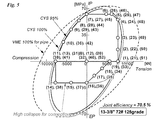
- FIG. 3 is a vertical cross-sectional view showing a fastening state of the threaded joint for oil country tubular goods according to the embodiment.
- FIG. 4 is a diagram showing the path of the combined load applied to the specimens # 1 to # 10.
- FIG. 5 is a diagram showing a path of a combined load applied to the specimens # 11 to # 20.
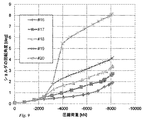
- FIG. 6 is a graph showing the relationship between the compression load and the shoulder rotation angle when a large simple compression load is gradually applied to the specimens # 1 to # 5.
- FIG. 7 is a graph showing the relationship between the compression load and the shoulder rotation angle when a large simple compression load is gradually applied to the specimens # 6 to # 10.
- FIG. 8 is a graph showing the relationship between the compression load and the shoulder rotation angle when a large simple compression load is gradually applied to the specimens # 11 to # 15.
- FIG. 9 is a graph showing the relationship between the compression load and the shoulder rotation angle when a large simple compression load is gradually applied to the specimens # 16 to # 20.
- FIG. 10 is a graph showing the angle of rotation of the shoulder in each load step of the two specimens # 1 and # 6 in which the axial length of the inner groove is changed.
- FIG. 11 is a graph showing the angle of rotation of the shoulder in each load step of the two specimens # 2 and # 7 in which the axial lengths of the inner grooves are changed.
- FIG. 12 is a graph showing the angle of rotation of the shoulder in each load step of the two specimens # 3 and # 8 in which the axial length of the inner groove is changed.
- FIG. 13 is a graph showing the angle of rotation of the shoulder in each load step of the two specimens # 4 and # 9 in which the axial length of the inner groove is changed.
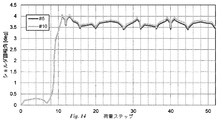
- FIG. 14 is a graph showing the angle of rotation of the shoulder in each load step of the two specimens # 5 and # 10 in which the axial lengths of the inner grooves are changed.
- FIG. 15 is a graph showing the angle of rotation of the shoulder in each load step of the two specimens # 11 and # 16 in which the axial length of the inner groove is changed.
- FIG. 16 is a graph showing the angle of rotation of the shoulder in each load step of the two specimens # 12 and # 17, in which the axial length of the inner groove is changed.
- FIG. 17 is a graph showing the angle of rotation of the shoulder at each load step of the two specimens # 13 and # 18 in which the axial length of the inner groove is changed.
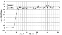
- FIG. 18 is a graph showing the angle of rotation of the shoulder at each load step of the two specimens # 14 and # 19 in which the axial lengths of the inner grooves are changed.
- FIG. 19 is a graph showing the angle of rotation of the shoulder at each load step of the two specimens # 15 and # 20 in which the axial lengths of the inner grooves are changed.
- the threaded joint according to the present embodiment is composed of a tubular pin and a tubular box.
- the pin and the box are fastened by screwing the pin into the box.
- the pin is provided at the end of the first tube and the box is provided at the end of the second tube.
- the first pipe may be a long pipe such as an oil well pipe.
- the second pipe may be a long pipe such as an oil well pipe, or may be a coupling for connecting the long pipes to each other.
- the well pipe and the coupling are typically made of steel, but may be made of a metal such as stainless steel or a nickel-based alloy.
- the pin can be provided with a male screw including an internal screw portion and an external screw portion separated in the axial direction, and an intermediate shoulder surface provided between the internal screw portion and the external screw portion of the male screw.
- the internal threaded portion and the external threaded portion are each composed of tapered threads.
- the internal thread portion can be arranged closer to the pipe end side than the external thread portion.
- the taper bus of the taper screw constituting the internal thread portion is located radially inward with the taper bus of the taper screw constituting the external thread portion.
- the intermediate shoulder surface can be formed by the side surface of the step portion formed on the outer circumference of the pin between the internal thread portion and the external thread portion. The intermediate shoulder surface is directed toward the tube end side of the pin.
- the internal threaded portion and the externally threaded portion may be trapezoidal threads, API round threads, API buttress threads, dovetail type threads, or the like, respectively.
- the box can be provided with a female screw including an internal screw portion and an external screw portion separated in the axial direction, and an intermediate shoulder surface provided between the internal screw portion and the external screw portion of the female screw.
- the internal and external threaded portions of the female thread consist of tapered threads that match the internal and external threaded portions of the male thread, respectively.
- the internal threaded portion of the female thread is fitted with the internal threaded portion of the male thread in the fastened state.
- the external threaded portion of the female thread is fitted with the external threaded portion of the male thread in the fastened state.
- the intermediate shoulder surface of the box can be formed by the side surface of the step portion formed on the inner circumference of the box between the internal thread portion and the external thread portion of the female thread.
- the intermediate shoulder surface of the box faces the tube end side of the box and faces the intermediate shoulder surface of the pin.
- the intermediate shoulder surface of the box contacts the intermediate shoulder surface of the pin in the fastened state, and these intermediate shoulder surfaces function as torque shoulders.
- the internal threaded portion and the external threaded portion of the female thread may be a trapezoidal thread, an API round thread, an API buttless thread, a dovetail type thread, or the like that is compatible with the internal threaded portion and the external threaded portion of the male thread, respectively.
- the intermediate shoulder surface of the pin and the box may be a surface orthogonal to the pipe axis, or may be a tapered surface inclined with respect to the orthogonal surface in the vertical cross section.
- an inner pin sealing surface is provided on the outer periphery of the pin on the tube end side of the first pipe with respect to the inner threaded portion of the pin, and inside the box on the tube center side of the second pipe with respect to the inner threaded portion of the box.
- a seal surface inside the box that interferes with the seal surface inside the pin in the fastened state can be provided on the periphery.
- the outer pin outer sealing surface is provided on the outer periphery of the pin on the tube center side of the first pipe with respect to the externally threaded portion of the pin, and the inside of the box is provided on the tube end side of the second pipe with respect to the externally threaded portion of the box.
- a box outer sealing surface that interferes with the pin outer sealing surface in the fastened state can be provided on the periphery.
- the inner seal surface of the pin and the inner seal surface of the box may be provided between the internal thread portion and the intermediate shoulder surface.
- the pin outer sealing surface and the box outer sealing surface may be provided between the external threaded portion and the intermediate shoulder surface.
- the load surfaces of the internal thread portion of the male screw and the internal thread portion of the female screw come into contact with each other, and the external thread portion of the male screw and the external thread portion of the female screw come into contact with each other.
- a gap is formed between the insertion surfaces of the internal thread portion of the male thread and the internal thread portion of the female thread, and a gap is formed between the external thread portion of the male thread and the insertion surface of the external thread portion of the female thread.
- the size of the gap formed between the insertion surfaces of the internal threaded portion of the male thread and the internal threaded portion of the female thread is uniform over the entire fitting range between the internal threaded portions, but is more uniform in some small regions. Large gaps may be formed.
- the size of the gap formed between the insertion surface of the external thread portion of the male thread and the external thread portion of the female thread is uniform over the entire fitting range between the external thread portions, but is more uniform in some small regions. Large gaps may be formed.
- the size of the gap formed between the insertion surface of the internal thread portion of the male thread and the internal thread portion of the female thread and the size of the gap formed between the insertion surface of the external thread portion of the male thread and the external thread portion of the female thread. are equal.
- the gap formed between the insertion surfaces of the internal threads of the male and female threads at the completion of fastening is smaller than the yield compressive load of the pin and box when a predetermined axial compressive load is applied.
- the insertion surfaces of the internal threads of the male and female threads are designed to be large enough to start contacting each other so as to bear a part of the axial compressive load.
- the contact state at the start of contact between the insertion surfaces of the internal threaded portion may vary, and the contact is started from a predetermined portion of the internal threaded portion in the pipe axial direction, and the insertion surface gradually increases as the axial compressive load increases.
- the contact area between the two may be widened, or the entire insertion surface of the internal thread portion may start contacting at the same time.
- the gap formed between the insertion surfaces of the external threads of the male and female threads at the completion of fastening is smaller than the yield compressive load of the pin and box when a predetermined axial compressive load is applied. Due to the deformation of the box, the insertion surfaces of the external threaded portions of the male and female threads start to come into contact with each other so as to bear a part of the axial compressive load.
- the contact state at the start of contact between the insertion surfaces of the externally threaded portions may vary, and the insertion surfaces gradually start contacting each other as the axial compressive load increases from a predetermined portion of the externally threaded portion in the pipe axial direction.
- the contact area may be widened, or the entire insertion surface of the internal thread portion may start contacting at the same time. Further, the axial compressive load at which the insertion surfaces of the externally threaded portions start contacting each other may be different from the axial compressive load at which the insertion surfaces of the internal threaded portions start contacting each other.
- the threaded pipe fitting according to the present disclosure satisfies the following formula (1).
- G is the size in the direction along the pipe axis direction of the gap formed between the insertion surfaces of the male and female threads at the time of completion of fastening
- Dsh is the intermediate shoulder surface of the pin in the vertical cross section at the completion of fastening.
- the size of the gap formed between the insertion surfaces means the size of the minimum gap portion formed between the insertion surfaces.
- the smaller of the two is the "male thread and female thread”. It is the size of the "gap formed between the insertion surfaces”. It is preferable that the outer peripheral edge of the intermediate shoulder surface of the pin and the inner peripheral edge of the intermediate shoulder surface of the box are all perfect circles, and the equation (1) can be satisfied in a state where the pin and the box are properly fastened without being loose. Just do it.
- the pipe axial distance TL1 between the portion where the insertion surfaces of the internal threads start to contact each other due to the load of the predetermined axial compressive load and the intermediate shoulder surface is the external thread due to the load of the predetermined axial compressive load.
- the pipe axial distance TL2 between the portion where the insertion surfaces of the portions start contacting and the intermediate shoulder surface is 0.8 to 1.2 times, more preferably 0.9 to 1.1 times. ..
- the relative displacement amount (that is, the amount of reduction in the size of the gap) between the insertion surfaces of the internal threaded portions due to the compressive strain and the contact starting portion between the insertion surfaces of the external threaded portions due to the compressive strain.
- the relative displacement amount can be made uniform. Therefore, it is possible to equalize the axial compression load at which the insertion surfaces of the internal threads start to contact each other and the axial compression load at which the insertion surfaces of the external threads start to contact each other.
- the size G of the gap formed between the insertion surfaces of the male and female threads in the direction along the tube axis direction at the time of completion of fastening may be, for example, 0.15 mm or less.
- the shoulder rotation angle of the intermediate shoulder exceeds 1 °.
- the size G of the gap formed between the insertion surfaces of the male and female threads at the completion of fastening is preferably 0.06 mm or more in the direction along the pipe axis direction.
- the pin has a sealing surface (in-pin sealing surface) provided on the tube end side of the male thread
- the box has a sealing surface (in-box sealing surface) that contacts the pin's sealing surface in the fastened state.
- An inner groove extending along the circumferential direction provided at a portion of the inner circumference of the box between the sealing surface of the box and the female screw is provided, and the inner groove accommodates a part of the male screw of the pin in the fastened state.
- the inner groove has a groove bottom having an axial width smaller than twice the screw pitch of the internal thread portion of the male thread.
- the intermediate shoulder surface of the pin and the box has a characteristic that the shoulder rotation angle ⁇ increases as the axial compression load applied increases.
- the shoulder rotation angle ⁇ at the time when the insertion surfaces of the male and female threads start to contact each other so as to bear a part of the axial compressive load is less than 1 °. According to this, the insertion surfaces of the male and female threads start to come into contact with each other before the increase in the angle of rotation of the shoulder increases, and the insertion surface also bears a part of the axial compression load, so that the angle of rotation ⁇ of the shoulder increases. You can prevent it from becoming too much.
- the oil country tubular goods threaded joint 1 is an integral type threaded joint, and is a tubular pin 2 and a tubular pin 2 to which the pin 2 is screwed and fastened to the pin 2. It includes a box 3.
- the pin 2 is provided at the end of one of the first and second well pipes T1 and T2 connected to each other, and the box 3 is provided at the end of the other well pipe T2.
- the pin 2 and the box have a structure in which the pin 2 formed at the end of the first oil well pipe T1 is fitted inside the box 3 formed at the end of the second oil well pipe T2.
- the pipe end of the oil well pipe T1 on which the pin 2 is formed is subjected to diameter reduction processing, and the pipe of the oil well pipe T2 on which the box 3 is formed is formed.
- the end portion is subjected to diameter expansion processing, and the pin 2 and the box 3 are formed by turning after these diameter reduction processing or diameter expansion processing.
- the pin outer sealing surface 21, the outer groove 22, and the taper screw are arranged in this order from the pipe center side (left side in FIG. 3) to the pipe end side (right side in FIG. 3) of the first oil well pipe T1.
- An internal threaded portion 27 made of a tapered screw having a diameter smaller than that of the external threaded portion 23 and an internal threaded portion 27, and a pin inner sealing surface 28 are provided.
- the external threaded portion 23 and the internal threaded portion 27 form a male screw having a two-step screw structure.
- Threaded portion 32, unthreaded portion 33 having an inner peripheral surface connected to the thread top surface of the external threaded portion 32, a stepped portion including an intermediate shoulder surface 34, a threadless portion 35 connected to the bottom surface of the thread valley of the internal threaded portion 36, and an external thread.
- An internal thread portion 36 composed of a tapered screw having a diameter smaller than that of the portion 32, an inner groove 37, and a box inner sealing surface 38 are provided.
- the external threaded portion 32 and the internal threaded portion 36 form a female thread having a two-step thread structure.
- the intermediate shoulder surface 25 of the pin 2 comes into contact with the intermediate shoulder surface 34 of the box 3.
- the fastening torque at this time is also called shouldering torque.
- the fastening torque rapidly increases due to the sliding contact between the intermediate shoulder surfaces 25 and 34.
- the intermediate shoulder surfaces 25 and 34 function as torque shoulders.
- the gap G is formed between the insertion surfaces of the external threaded portions 23 and 32 due to elastic deformation of the pin and the box, as well as the insertion surfaces of the external thread portions 23 and 32.
- the size is such that the insertion surfaces of the internal threaded portions 27 and 36 start to come into contact with each other so as to bear a part of the axial compressive load.
- the yield compressive load is the compressive load when the yield point is reached. When the yield point is exceeded, the plastic strain of each part of the pin 2 and the box 3 rapidly progresses, and it becomes impossible to bear a load exceeding the yield compression load, and the threaded joint 1 is destroyed.
- the pin outer sealing surface 21 and the box outer sealing surface 31 interfere with each other over the entire circumference, whereby the external pressure sealing performance is mainly obtained.
- the inner seal surface 28 of the pin and the inner seal surface 38 of the box interfere with each other over the entire circumference, whereby the internal pressure sealing performance is mainly obtained.
- the pin 2 tends to shrink inward in the radial direction, but the taper angle ⁇ p of the pin inner seal surface 28 forming the inner seal and the taper angle ⁇ b of the box inner seal surface 38
- the contact position between the sealing surfaces 28 and 38 is separated from the pipe end side of the pin, so that the influence of the above-mentioned reduced diameter deformation can be mitigated, and the sealing performance under a compressive load can be reduced. It is thought that it will lead to improvement.
- the outer groove 22 is provided in a portion of the outer circumference of the pin between the pin outer sealing surface 21 and the outer screw portion 23.
- the outer groove 22 extends along the circumferential direction, preferably extending over the entire circumference.
- the outer groove 22 accommodates a part of the outer thread portion 32 of the female thread of the box 3.
- the outer groove 22 has a groove bottom having an axial width smaller than twice the thread pitch of the external thread portion 32 of the box 3.
- the inner groove 37 is provided in a portion of the inner circumference of the box between the inner sealing surface 38 of the box and the inner threaded portion 36.
- the inner groove 37 extends along the circumferential direction, and preferably extends over the entire circumference.
- the inner groove 37 accommodates a part of the inner thread portion 27 of the male thread of the pin 2.
- the inner groove 37 has a groove bottom 37a having an axial width W smaller than twice the thread pitch of the internal threaded portion 27 of the pin 2.
- the threaded joint 1 has a pin danger cross section PCCS in the range where the outer groove 22 is provided, and has a box danger cross section BCCS in the range where the inner groove 37 is provided.
- the box 3 has a box intermediate danger cross section BICCS in the vicinity of the end portion on the intermediate shoulder surface 34 side of the meshing range of the external thread portion 23 of the male thread and the external thread portion 32 of the female thread.
- the pin 2 has a pin intermediate danger cross section PICCS in the vicinity of the end portion on the intermediate shoulder surface 25 side of the meshing range between the internal thread portion 27 of the male thread and the internal thread portion 36 of the female thread.
- the dangerous cross section is a vertical cross section of a joint portion having the smallest area that can withstand a tensile load in the fastened state.
- CCS The dangerous cross section
- the one with the smallest cross-sectional area is the dangerous cross section.
- the ratio of the area of the dangerous cross section to the cross-sectional area of the pipe body of the oil country tubular goods T1 is called the joint efficiency, and is widely used as an index of the tensile strength of the joint portion with respect to the tensile strength of the oil country tubular goods body.
- the threaded joint 1 having a two-step screw structure in addition to the box dangerous cross section BCCS and the pin dangerous cross section PCCS, there is a portion in the axial middle portion of the joint portion where the joint cross section that can withstand a tensile load becomes small. That is, in a threaded joint having a two-stage thread structure, there is a section without screw fitting in the middle in the axial direction. In this non-screwed section, the tensile load shared by the pins and the box propagates axially without increasing or decreasing.
- the cross section of the pin having the smallest cross section in the section without screw fitting is the pin intermediate dangerous cross section (PICCS)
- the cross section of the box having the smallest cross section in the section without screw fitting is the box intermediate dangerous cross section (PICCS).
- BICCS BICCS
- the unscrewed portion 24 of the pin 2 is inserted into the unscrewed portion 33 of the box 3, and the unscrewed portion 26 of the pin 2 is inserted into the unscrewed portion 35 of the box 3.
- a gap is formed between the screwless portion 24 and the screwless portion 33, and between the screwless portion 26 and the screwless portion 35.
- the intermediate shoulder surfaces 25 and 34 are each composed of flat surfaces orthogonal to the pipe axis in an unfastened state. Instead, the intermediate shoulder surfaces 25, 34 may be slightly inclined with respect to the plane orthogonal to the pipe axis in the unfastened state.
- the oil country tubular goods threaded joint 1 of the present embodiment includes intermediate shoulder surfaces 25 and 34 and internal threaded portions 27 and 36 of male and female threads so as to satisfy the following formula (1).
- G is the size of the gap formed between the insertion surfaces of the internal thread portions 27 and 36 of the male and female threads at the time of completion of fastening in the direction along the pipe axis direction
- Dsh is the longitudinal section at the time of completion of fastening. This is the distance between the radial outer end of the intermediate shoulder surface 25 of the pin 2 and the radial inner end of the intermediate shoulder surface 34 of the box 3 on the surface.
- the size of the gap formed between the insertion surfaces of the external thread portions 23 and 32 of the male and female threads at the completion of fastening in the direction along the pipe axis is the internal thread of the male and female threads at the completion of fastening.
- the size of the gap formed between the insertion surfaces of the portions 27 and 36 in the direction along the pipe axis direction is determined by the internal threaded portions 27 of the male and female threads when the fastening is completed.
- the size of the gap formed between the insertion surfaces of 36 in the direction along the pipe axis may be different, but even in this case, between the insertion surfaces of the external thread portions 23 and 32 of the male and female threads at the completion of fastening. It is preferable that the size of the gap formed in 1 in the direction along the pipe axis direction also satisfies the above formula (1).
- the outer diameter of the well pipe T1 connected by the threaded joint 1 is 180 mm or more and less than 380 mm, more preferably 240 mm or more and less than 360 mm, it is preferable to satisfy G ⁇ 0.15 mm. Further, in order to prevent seizure during fastening, it is preferable to satisfy G ⁇ 0.06 mm.
- each screw may be a trapezoidal screw, an API round screw, an API buttress screw, a dovetail type screw, or the like.
- present disclosure is not limited to the above-described embodiment, and various changes can be made without departing from the spirit of the present disclosure.
- Table 1 shows the main dimensions of the threaded joints used in the analysis.
- Dout is the outer diameter of the pipe body of the oil well pipe T1
- Din is the inner diameter of the pipe body of the oil well pipe T1
- JE is the joint efficiency
- TL1 is the part where the insertion surfaces of the internal threads 27 and 36 start to contact each other (
- TL2 is the insertion surface of the external thread portion 23 and 32.
- the pipe axial distance between the portion where the insertion surfaces start to contact each other (in the present embodiment, the end of the insertion surface of the external thread portion 23 of the male screw on the pin tube body side) and the intermediate shoulder surfaces 25 and 34, G is fastened.
- the gap between the insertion surfaces at the time of completion, W, is the width of the groove bottom of the inner groove 27 in the pipe axial direction.
- the screw taper angle of each screw portion 23, 27, 32, 36 is 1.591 ° (1/18), the thread height (load surface side) is 1.3 mm, and the screw pitch is 5. It was unified to 08 mm.
- FIG. 4 shows the path of the combined load applied to the specimens # 1 to # 10 having a tube size of 9-5 / 8 "47 # (tube body outer diameter 244.48 mm, tube body inner diameter 220.50 mm).
- Reference numeral 5 denotes a path of the combined load applied to the specimens # 11 to # 20 having a pipe size of 13-3 / 8 "72 # (tube body outer diameter 339.73 mm, pipe body inner diameter 313.61 mm).
- specimens # 5 and # 10 are about -2800kN
- specimens # 4 and # 9 are about -2000kN
- specimens # 3 is about -1500kN
- specimens # 2 and # 7 are about -1300kN
- specimens # 1 and # 6 are less than -1000kN
- the inclination of the shoulder rotation angle is caused by the start of contact between the insertion surfaces.
- the gap between the insertion surfaces is larger than 0.15 mm
- the insertion surfaces are in contact with each other after the slope of the shoulder rotation angle becomes large, causing great damage to the intermediate shoulder surface. Is considered to have occurred.
- the shoulder rotation angle increases to about 3.0 ° in the load step 11, and is large in the subsequent load steps. You can grasp the tendency of accumulated damage.
- the shoulder rotation angle exceeded 4.0 ° in the load step 11, and was around 3.5 ° in the subsequent load step. It is transitioning with.
- Pipe thread joint 2 Pin, 23: Male thread (external thread), 27: Male thread (internal thread), 25: Intermediate shoulder surface 3: Box, 32: Female thread (external thread), 36: Female thread (inner) Threaded part), 34: Intermediate shoulder surface
Landscapes
- Engineering & Computer Science (AREA)
- General Engineering & Computer Science (AREA)
- Mechanical Engineering (AREA)
- Geology (AREA)
- Life Sciences & Earth Sciences (AREA)
- Mining & Mineral Resources (AREA)
- Environmental & Geological Engineering (AREA)
- Fluid Mechanics (AREA)
- General Life Sciences & Earth Sciences (AREA)
- Geochemistry & Mineralogy (AREA)
- Physics & Mathematics (AREA)
- Non-Disconnectible Joints And Screw-Threaded Joints (AREA)
- Earth Drilling (AREA)
Priority Applications (10)
| Application Number | Priority Date | Filing Date | Title |
|---|---|---|---|
| US17/754,535 US12320206B2 (en) | 2020-01-17 | 2020-12-22 | Threaded connection for pipe |
| CN202080079293.0A CN114761722B (zh) | 2020-01-17 | 2020-12-22 | 管用螺纹接头 |
| JP2021571119A JP7455866B2 (ja) | 2020-01-17 | 2020-12-22 | 管用ねじ継手 |
| BR112022003470-9A BR112022003470B1 (pt) | 2020-01-17 | 2020-12-22 | Conexão roscada para tubo |
| MX2022006279A MX2022006279A (es) | 2020-01-17 | 2020-12-22 | Conexion roscada para tubo. |
| AU2020423747A AU2020423747B2 (en) | 2020-01-17 | 2020-12-22 | Threaded connection for pipe |
| EP20913326.3A EP4092302B1 (en) | 2020-01-17 | 2020-12-22 | Threaded connection for pipe |
| CA3150307A CA3150307C (en) | 2020-01-17 | 2020-12-22 | Threaded connection for pipe |
| UAA202201838A UA129064C2 (uk) | 2020-01-17 | 2020-12-22 | Нарізне з'єднання для труб |
| PL20913326.3T PL4092302T3 (pl) | 2020-01-17 | 2020-12-22 | Połączenie gwintowe rur |
Applications Claiming Priority (2)
| Application Number | Priority Date | Filing Date | Title |
|---|---|---|---|
| JP2020005810 | 2020-01-17 | ||
| JP2020-005810 | 2020-01-17 |
Publications (1)
| Publication Number | Publication Date |
|---|---|
| WO2021145161A1 true WO2021145161A1 (ja) | 2021-07-22 |
Family
ID=76863717
Family Applications (1)
| Application Number | Title | Priority Date | Filing Date |
|---|---|---|---|
| PCT/JP2020/047835 Ceased WO2021145161A1 (ja) | 2020-01-17 | 2020-12-22 | 管用ねじ継手 |
Country Status (10)
| Country | Link |
|---|---|
| US (1) | US12320206B2 (https=) |
| EP (1) | EP4092302B1 (https=) |
| JP (1) | JP7455866B2 (https=) |
| CN (1) | CN114761722B (https=) |
| AR (1) | AR121025A1 (https=) |
| AU (1) | AU2020423747B2 (https=) |
| MX (1) | MX2022006279A (https=) |
| PL (1) | PL4092302T3 (https=) |
| UA (1) | UA129064C2 (https=) |
| WO (1) | WO2021145161A1 (https=) |
Citations (10)
| Publication number | Priority date | Publication date | Assignee | Title |
|---|---|---|---|---|
| JPH09126366A (ja) * | 1995-10-03 | 1997-05-13 | Vallourec Oil & Gas | 管のねじ継手 |
| JPH10169855A (ja) * | 1996-12-05 | 1998-06-26 | Sumitomo Metal Ind Ltd | 大径油井管用ねじ継手 |
| JP2001124253A (ja) * | 1999-10-29 | 2001-05-11 | Kawasaki Steel Corp | 鋼管用ネジ継手 |
| US6530607B1 (en) * | 2000-11-06 | 2003-03-11 | Hydril Company | Two-step threaded connector having differential thread width |
| JP2006526747A (ja) * | 2003-06-06 | 2006-11-24 | 住友金属工業株式会社 | 鋼管用ねじ継手 |
| US20080296894A1 (en) * | 2007-05-29 | 2008-12-04 | Grant Prideco, L.P. | Oilfield threaded connections |
| JP2012149760A (ja) | 2010-06-30 | 2012-08-09 | Jfe Steel Corp | 管用ねじ継手 |
| WO2016056222A1 (ja) | 2014-10-06 | 2016-04-14 | 新日鐵住金株式会社 | 鋼管用ねじ継手 |
| WO2017104282A1 (ja) * | 2015-12-15 | 2017-06-22 | 新日鐵住金株式会社 | 鋼管用ねじ継手 |
| WO2018211873A1 (ja) | 2017-05-15 | 2018-11-22 | 新日鐵住金株式会社 | 鋼管用ねじ継手 |
Family Cites Families (20)
| Publication number | Priority date | Publication date | Assignee | Title |
|---|---|---|---|---|
| US5348350A (en) * | 1980-01-19 | 1994-09-20 | Ipsco Enterprises Inc. | Pipe coupling |
| US4688832A (en) * | 1984-08-13 | 1987-08-25 | Hydril Company | Well pipe joint |
| US4696498A (en) * | 1986-10-29 | 1987-09-29 | Quanex Corporation | Tubular connection |
| JPH0631661B2 (ja) * | 1987-02-23 | 1994-04-27 | 新日本製鐵株式会社 | 低応力・高気密油井管用ネジ継手 |
| US5415442A (en) * | 1992-03-09 | 1995-05-16 | Marubeni Tubulars, Inc. | Stabilized center-shoulder-sealed tubular connection |
| EP0703396B1 (en) * | 1994-09-23 | 2000-04-05 | Sumitomo Metal Industries, Ltd. | Threaded joint for oil well pipes |
| JPH09119564A (ja) * | 1994-11-22 | 1997-05-06 | Sumitomo Metal Ind Ltd | 油井管用ねじ継手 |
| US6485063B1 (en) | 1996-05-15 | 2002-11-26 | Huey P. Olivier | Connection |
| AU776056B2 (en) * | 1999-04-30 | 2004-08-26 | Vam Usa, Llc | Threaded connection with high compressive rating |
| US6682101B2 (en) | 2002-03-06 | 2004-01-27 | Beverly Watts Ramos | Wedgethread pipe connection |
| US7527304B2 (en) * | 2004-12-30 | 2009-05-05 | Hydril Llc | Floating wedge thread for tubular connection |
| MX2008012234A (es) * | 2006-03-31 | 2008-11-25 | Sumitomo Metal Ind | Junta roscada tubular. |
| US7780202B2 (en) * | 2007-09-05 | 2010-08-24 | Grant Prideco, Lp | Oilfield tubular connection with increased compression capacity |
| WO2010059145A1 (en) * | 2008-11-24 | 2010-05-27 | Vam Usa, Llc | Oilfield threaded connections |
| JP2014013052A (ja) * | 2012-07-04 | 2014-01-23 | Jfe Steel Corp | 管のねじ継手 |
| US10774958B2 (en) * | 2016-01-25 | 2020-09-15 | Nippon Steel Corporation | Threaded joint for steel pipe |
| CN108700230B (zh) * | 2016-02-23 | 2019-11-22 | 日本制铁株式会社 | 钢管用螺纹接头 |
| CN110476000B (zh) * | 2017-03-31 | 2021-08-24 | 日本制铁株式会社 | 钢管用螺纹接头 |
| CA3149749C (en) | 2020-01-17 | 2024-03-26 | Satoshi Maruta | Threaded connection for pipe |
| PL4092304T3 (pl) | 2020-01-17 | 2024-06-10 | Nippon Steel Corporation | Połączenie gwintowe do rur |
-
2020
- 2020-12-22 CN CN202080079293.0A patent/CN114761722B/zh active Active
- 2020-12-22 UA UAA202201838A patent/UA129064C2/uk unknown
- 2020-12-22 MX MX2022006279A patent/MX2022006279A/es unknown
- 2020-12-22 WO PCT/JP2020/047835 patent/WO2021145161A1/ja not_active Ceased
- 2020-12-22 JP JP2021571119A patent/JP7455866B2/ja active Active
- 2020-12-22 US US17/754,535 patent/US12320206B2/en active Active
- 2020-12-22 PL PL20913326.3T patent/PL4092302T3/pl unknown
- 2020-12-22 AU AU2020423747A patent/AU2020423747B2/en active Active
- 2020-12-22 EP EP20913326.3A patent/EP4092302B1/en active Active
-
2021
- 2021-01-12 AR ARP210100066A patent/AR121025A1/es active IP Right Grant
Patent Citations (10)
| Publication number | Priority date | Publication date | Assignee | Title |
|---|---|---|---|---|
| JPH09126366A (ja) * | 1995-10-03 | 1997-05-13 | Vallourec Oil & Gas | 管のねじ継手 |
| JPH10169855A (ja) * | 1996-12-05 | 1998-06-26 | Sumitomo Metal Ind Ltd | 大径油井管用ねじ継手 |
| JP2001124253A (ja) * | 1999-10-29 | 2001-05-11 | Kawasaki Steel Corp | 鋼管用ネジ継手 |
| US6530607B1 (en) * | 2000-11-06 | 2003-03-11 | Hydril Company | Two-step threaded connector having differential thread width |
| JP2006526747A (ja) * | 2003-06-06 | 2006-11-24 | 住友金属工業株式会社 | 鋼管用ねじ継手 |
| US20080296894A1 (en) * | 2007-05-29 | 2008-12-04 | Grant Prideco, L.P. | Oilfield threaded connections |
| JP2012149760A (ja) | 2010-06-30 | 2012-08-09 | Jfe Steel Corp | 管用ねじ継手 |
| WO2016056222A1 (ja) | 2014-10-06 | 2016-04-14 | 新日鐵住金株式会社 | 鋼管用ねじ継手 |
| WO2017104282A1 (ja) * | 2015-12-15 | 2017-06-22 | 新日鐵住金株式会社 | 鋼管用ねじ継手 |
| WO2018211873A1 (ja) | 2017-05-15 | 2018-11-22 | 新日鐵住金株式会社 | 鋼管用ねじ継手 |
Non-Patent Citations (1)
| Title |
|---|
| See also references of EP4092302A4 |
Also Published As
| Publication number | Publication date |
|---|---|
| AU2020423747B2 (en) | 2023-09-07 |
| EP4092302B1 (en) | 2023-12-13 |
| PL4092302T3 (pl) | 2024-04-22 |
| JPWO2021145161A1 (https=) | 2021-07-22 |
| AR121025A1 (es) | 2022-04-06 |
| BR112022003470A2 (pt) | 2022-05-24 |
| EP4092302A1 (en) | 2022-11-23 |
| MX2022006279A (es) | 2022-06-08 |
| EP4092302A4 (en) | 2023-01-18 |
| US20230313620A1 (en) | 2023-10-05 |
| UA129064C2 (uk) | 2025-01-01 |
| CN114761722B (zh) | 2024-01-02 |
| AU2020423747A1 (en) | 2022-02-24 |
| CN114761722A (zh) | 2022-07-15 |
| EP4092302C0 (en) | 2023-12-13 |
| JP7455866B2 (ja) | 2024-03-26 |
| CA3150307A1 (en) | 2021-07-22 |
| US12320206B2 (en) | 2025-06-03 |
Similar Documents
| Publication | Publication Date | Title |
|---|---|---|
| EP3043098B1 (en) | Threaded connection for steel pipe | |
| JP7290738B2 (ja) | ねじ継手 | |
| WO2016056222A1 (ja) | 鋼管用ねじ継手 | |
| JP7367069B2 (ja) | 管用ねじ継手 | |
| JP6683738B2 (ja) | 鋼管用ねじ継手 | |
| BR112016026808B1 (pt) | Junta rosqueada para canos de aço | |
| JP7352738B2 (ja) | 鋼管用ねじ継手 | |
| JP6037091B1 (ja) | 管ねじ継手 | |
| JPWO2017104282A1 (ja) | 鋼管用ねじ継手 | |
| WO2019093163A1 (ja) | 鋼管用ねじ継手 | |
| WO2018211873A1 (ja) | 鋼管用ねじ継手 | |
| JP7150878B2 (ja) | 鋼管用ねじ継手 | |
| WO2011040262A1 (ja) | 鋼管用ねじ継手 | |
| WO2021145161A1 (ja) | 管用ねじ継手 | |
| JP7431863B2 (ja) | 管用ねじ継手 | |
| JP2024114125A (ja) | 管用ねじ継手 | |
| WO2020039875A1 (ja) | 鋼管用ねじ継手 | |
| WO2024171885A1 (ja) | ねじ継手 | |
| CA3150307C (en) | Threaded connection for pipe | |
| WO2024106291A1 (ja) | 鋼管用ねじ継手 | |
| JP2024123398A (ja) | 管用ねじ継手 | |
| EA044724B1 (ru) | Резьбовое соединение для труб | |
| EA044575B1 (ru) | Резьбовое соединение для трубы |
Legal Events
| Date | Code | Title | Description |
|---|---|---|---|
| 121 | Ep: the epo has been informed by wipo that ep was designated in this application |
Ref document number: 20913326 Country of ref document: EP Kind code of ref document: A1 |
|
| ENP | Entry into the national phase |
Ref document number: 2021571119 Country of ref document: JP Kind code of ref document: A |
|
| ENP | Entry into the national phase |
Ref document number: 2020423747 Country of ref document: AU Date of ref document: 20201222 Kind code of ref document: A |
|
| ENP | Entry into the national phase |
Ref document number: 3150307 Country of ref document: CA |
|
| REG | Reference to national code |
Ref country code: BR Ref legal event code: B01A Ref document number: 112022003470 Country of ref document: BR |
|
| WWE | Wipo information: entry into national phase |
Ref document number: 140150140003001524 Country of ref document: IR |
|
| ENP | Entry into the national phase |
Ref document number: 112022003470 Country of ref document: BR Kind code of ref document: A2 Effective date: 20220223 |
|
| WWE | Wipo information: entry into national phase |
Ref document number: DZP2022000311 Country of ref document: DZ |
|
| NENP | Non-entry into the national phase |
Ref country code: DE |
|
| ENP | Entry into the national phase |
Ref document number: 2020913326 Country of ref document: EP Effective date: 20220817 |
|
| WWG | Wipo information: grant in national office |
Ref document number: 17754535 Country of ref document: US |
|
| WWG | Wipo information: grant in national office |
Ref document number: MX/A/2022/006279 Country of ref document: MX |