WO2021141031A1 - 刃物、道具 - Google Patents
刃物、道具 Download PDFInfo
- Publication number
- WO2021141031A1 WO2021141031A1 PCT/JP2021/000136 JP2021000136W WO2021141031A1 WO 2021141031 A1 WO2021141031 A1 WO 2021141031A1 JP 2021000136 W JP2021000136 W JP 2021000136W WO 2021141031 A1 WO2021141031 A1 WO 2021141031A1
- Authority
- WO
- WIPO (PCT)
- Prior art keywords
- protrusion
- handle
- blade
- tongue
- receiving portion
- Prior art date
- Legal status (The legal status is an assumption and is not a legal conclusion. Google has not performed a legal analysis and makes no representation as to the accuracy of the status listed.)
- Ceased
Links
Images


Classifications
-
- B—PERFORMING OPERATIONS; TRANSPORTING
- B26—HAND CUTTING TOOLS; CUTTING; SEVERING
- B26B—HAND-HELD CUTTING TOOLS NOT OTHERWISE PROVIDED FOR
- B26B5/00—Hand knives with one or more detachable blades
-
- B—PERFORMING OPERATIONS; TRANSPORTING
- B26—HAND CUTTING TOOLS; CUTTING; SEVERING
- B26B—HAND-HELD CUTTING TOOLS NOT OTHERWISE PROVIDED FOR
- B26B1/00—Hand knives with adjustable blade; Pocket knives
- B26B1/02—Hand knives with adjustable blade; Pocket knives with pivoted blade
-
- B—PERFORMING OPERATIONS; TRANSPORTING
- B26—HAND CUTTING TOOLS; CUTTING; SEVERING
- B26B—HAND-HELD CUTTING TOOLS NOT OTHERWISE PROVIDED FOR
- B26B3/00—Hand knives with fixed blades
Definitions
- the present invention relates to a blade mainly used outdoors, and relates to a structure of a portion for attaching a handle to the tongue of the blade.
- the blade disclosed in Patent Document 1 has a tongue expressed as a core of the blade inserted into a handle expressed as a grip and fixed with a set screw screwed into a screw hole provided in the handle. Therefore, a structure for connecting to both the tongue and the handle is required, and it is not easy for the person using the knife to change the handle suitable for his / her taste and purpose.
- the present invention has been made in view of the above background technology, and provides a blade that does not require a structure for connecting a tongue to a handle and that allows a person who uses the blade to easily change the handle according to his / her taste and purpose of use. With the goal.
- a blade (tool) in which a blade (tip member) and a tongue (mounting body) are integrated into a plate, or a blade (tip member) and a tongue (mounting body) are foldably connected.
- a protrusion that can bite into the handle is separated from the tongue (mounting body) and protrudes to the rear side of the tongue (mounting body) on the front side of the tongue (mounting body). It is characterized in that a receiving portion that is provided and receives a handle that bites into the protrusion is provided on the rear side of the tongue (mounting body portion), or a blade (tip member) and a tongue (mounting body portion) are provided.
- scabbard Is foldable and connected to the scabbard in the front and rear, and a protrusion that can bite into the handle is foldably connected to the scabbard (tip member).
- the tongue (mounting body portion) is developed from the sheath portion so as to receive the handle that bites into the protrusion portion.
- a protrusion capable of biting into a handle is separated from the tongue on the front side of the tongue.
- a structure for connecting the tongue to the handle is unnecessary because the tongue is provided so as to project to the rear side and a receiving portion for receiving the handle biting into the protrusion is provided on the rear side of the tongue. Therefore, it is easy for the person who uses the knife to change the handle according to his / her taste and purpose.
- a protrusion capable of biting into the handle is foldably connected to the sheath portion.
- Bottom view of the blade according to the fourth embodiment for carrying out the invention as viewed from the direction of arrow A in FIG. The side view which shows the blade which concerns on Embodiment 5 for carrying out an invention.
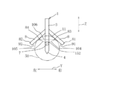
- the blade 1 exemplifies a spear knife that is used like a spear with a handle 50 attached, and the blade 2 and the tongue 3 are integrated into a plate shape.
- the blade 2 has a plate shape extending from one end to the other end, and has blades 4 and 5 as double-edged blades at the upper and lower portions in a direction intersecting the longitudinal direction X of the blade 2, and both upper and lower blades.
- a point 6 as a cutting edge is provided at a portion where the blades 4 and 5 of the above intersect with each other.
- the tongue 3 has a plate shape extending from one end of the blade 2 in the front-rear direction as the longitudinal direction X of the blade 2.
- the blade 5 may not be provided.
- the blade 4 and the protrusion 7 are provided on the center line 103. Since the blade 4 and the protrusion 7 are arranged in a straight line, even when a force in the direction of piercing the blade 1 is applied, the force does not shift in the left-right direction and the handle passes through the protrusion 7. Can tell 50.
- a protrusion 7 capable of biting into a handle 50 made of a wooden stick such as a tree branch is provided so as to separate from the tongue 3 and project to the rear side of the tongue 3. Be done.
- a first receiving portion 8 for receiving the handle 50 that bites into the protrusion 7 is provided.
- the first receiving portion 8 includes a first right receiving portion 81 and a first left receiving portion 82, the first right receiving portion 81 is provided with a first right protrusion 83, and the first left receiving portion 82 is provided with a first right receiving portion 83.
- 1 Left protrusion 84 is provided.
- the first receiving portion 8 is a set of two first right receiving portions 81 and two first left receiving portions 82.
- the first right protrusion 83 is provided at a position to the right of the blade 4 and the protrusion 7.
- the first left protrusion 84 is provided at a position to the left of the blade 4 and the protrusion 7.
- the first right protrusion 83 and the first left protrusion 84 are provided symmetrically with respect to the center line 103.
- the first receiving portion 8 projecting on both the left and right sides of the tongue 3 is opened downward and forms a downward recess 11 toward the projecting side from the side of the tongue 3, and the recess 11 is formed. Support the handle 50 so that it does not sway from side to side.
- the handle 50 is attached to the blade 1 as the end surface of one end of the handle 50 is pushed from the tip side of the protrusion 7 toward the front side of the tongue 3, the protrusion is formed. Since the handle 50 is attached to the blade 1 by receiving the other end side extending to the rear side of the tongue 3 of the handle 50 that bites into the portion 7 to the first receiving portion 8, the tongue is connected to the handle 50.
- the structure is not required, and it is easy for the person using the blade 1 to replace the handle 50 suitable for his / her taste and purpose of use.
- the handle 50 is a long rod, it can be used as a spear, and if the handle 50 is a short piece of wood or the like, a person can hold the tongue 3 and the handle 50 and use it like a knife.
- a rod with a non-smooth peripheral surface such as a tree branch can be used for the handle 50, and the thickness of the handle 50 does not require a precise dimensional thickness, and the thickness of the tree branch attached to the blade 1 is not required. There is a degree of freedom.
- the virtual line 104 connecting the protrusion 7 and the first right protrusion 83, the virtual line 105 connecting the protrusion 7 and the first left protrusion 84, and the first right protrusion 83 A bottom-view triangle 151 drawn with a virtual line 106 connecting the first left protrusion 84 is formed.
- the blade 1 and the handle 50 are stably fixed by forming the triangle 151 by fixing the protrusion 7, the first right protrusion 83, and the first left protrusion 84 at three places.
- the triangle 151 is preferably an isosceles triangle in which the virtual line 104 and the virtual line 105 have the same length, and the blade 1 and the handle 50 are evenly fixed in the left-right direction to ensure a stable connection.
- the virtual line 104 connecting the protrusion 7 and the first right protrusion 83, and the protrusion 7 and the third 1 If the rear view triangle 152 drawn by the virtual line 105 connecting the left protrusion 84 and the virtual line 106 connecting the first right protrusion 83 and the first left protrusion 84 is formed, the protrusion 7 And the first right protrusion 83 and the first left protrusion 84 are fixed at three places to form the triangle 152, so that the handle 50 and the blade 1 are more stably connected, which is preferable.
- the rear view triangle 152 is preferably an isosceles triangle.
- FIG. 3 the case where the protrusion 7 is provided above the first right protrusion 83 and the first left protrusion 84 is illustrated, but the protrusion 7 is provided on the first right protrusion 83 and the first left. Even if it is provided below the protrusion 84, stable connection is possible if the triangle 152 in the rear view is formed.
- the blade 1 and the handle 50 can be stably fixed, but if the bottom-viewing triangle 151 and the back-viewing triangle 152 are formed together, the blade 1 and the handle 50 are formed. Becomes a more stable fixed state.
- the first right-side receiving portion 81 and the first left-side receiving portion 82 of the first receiving portion 8 project from the tongue 3 on both the left and right sides, and are centerlines. It is symmetrical around 103. Further, a case where the first right protrusion 83 and the first left protrusion 84 are provided at symmetrical positions with respect to the center line 103 has been illustrated.
- the left and right sides of the first receiving portion 8 are lateral directions Y intersecting in the front-rear direction as the longitudinal direction X of the blade 2 in the tongue 3.
- the first right-side receiving portion 81 and the first left-side receiving portion 82 may protrude from positions shifted back and forth in the longitudinal direction X. Even in such a case, if the first right protrusion 83 and the first left protrusion 84 are provided at symmetrical positions with respect to the center line 103, the virtual line 104, the virtual line 105, and the virtual line 106 can be formed.
- the bottom-viewing triangle 151 drawn in is an isosceles triangle, which is more preferable.
- the surface 91 on the side of the first right receiving portion 81 in contact with the handle 50 and the handle 50 of the first left receiving portion 82 shown in FIG. 3 are not provided.
- the surface 92 on the side in contact with the surface may be flat.
- the flat surface of the first right side receiving portion 81 in contact with the handle 50 and the peripheral surface of the handle 50 are in contact with each other, and the flat surface of the first left side receiving portion 82 in contact with the handle 50 is in contact with the peripheral surface of the handle 50.
- the structure may be such that the first receiving portion 8 can receive the handle 50 evenly on the left and right sides.
- the first receiving portion 8 may use the same structure as a holder of a cylindrical body such as a round bar called a V block or a bevel stand. Even in such a case, the contact portion between the handle 50 and the surface 91 of the first right side receiving portion 81 on the side in contact with the handle 50 is on the right side of the blade 4 and the protrusion 7, and the handle 50 and the first left receiving portion 82 If the contact portion with the surface 92 on the side in contact with the handle 50 is on the left side of the blade 4 and the protrusion 7, the triangle 151 and / or the bottom view triangle 151 at three points of these two contact portions and the protrusion 7. Alternatively, a triangle 152 viewed from the rear is formed, and the blade 1 and the handle 50 can be connected to each other, so that stable connection is possible.
- both the tongue 3 and the handle 50 are held by a binding member 51 such as a string or a rope. If tied from the outside, the first right protrusion 83 and the first left protrusion 84 can be fixed in a state of being bitten into the peripheral surface of the handle 50, and the handle 50 can be stably attached to the tongue 3.
- both the handle 50 and the tongue 3 are tied with the binding member 51 in this way, since one end of the handle 50 bites into the protrusion 7 and is in a temporarily fixed state, both the handle 50 and the tongue 3 are tied. Easy to bind with member 51.
- the handle 50 and the tongue 3 can be connected by passing one end side of the binding member 51 through the through hole 52.
- the binding member 51 makes it easier to bind.
- the number of through holes 52 may be two, three, or a plurality of four or more.
- the non-slip portion (not shown) for the binding member 51 is convex or concave on the back portion 10 of the tongue 3. If provided, the tongue 3 and the handle 50 can be appropriately tied together without the binding member 51 coming off the tongue 3.
- first receiving portion 8 is provided on the tongue 3 in the embodiment for carrying out the present invention, but a plurality of first receiving portions 8 may be individually provided before and after the tongue 3.
- the protrusion 7 may be provided detachably from the front portion of the tongue 3. If the protrusion 7 loses its sharpness, it can be replaced, which is preferable.
- a structure is applied in which a connecting portion 36 having a male screw protruding forward of the protrusion 7 and a connected portion 37 having a female screw provided in a hole recessed forward from the front portion of the tongue 3 are provided. it can.
- a plate-shaped portion 38 projecting from the front to the rear of the tongue 3 is provided.
- the plate-shaped portion 38 and the tongue 3 are provided in an integral plate shape.
- a twisted portion 39 in which the plate-shaped portion 38 on the side of the blade 2 side of the connected portion 37 is twisted 90 degrees is provided.
- a bent portion 40 bent in the Z (vertical) direction is created between the twisted portion 39 and the connected portion 37 so that the connected portion 37 and the connecting portion 36 can be attached and detached in the front-rear direction of the longitudinal direction X.
- the structure may be provided.
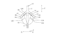
- the blade 1 according to the second embodiment shown in FIG. 4 is an example of a spear knife attached with a handle 50 and used like a spear, and the blade 2 and the tongue 3 are integrated into a plate shape.
- the second receiving portion 13 is provided on the protrusion 7 and the tongue 3, which is different from the first embodiment, and the other parts are the same.
- the blade 4 and the protrusion 7 are provided on the center line 103. Since the blade 4 and the protrusion 7 are arranged in a straight line, even when a force in the direction of piercing the blade 1 is applied, the force does not shift in the left-right direction and the handle passes through the protrusion 7. Can tell 50.
- a second receiving portion 13 that receives the handle 50 jointly with the protrusion 7 is provided on the side of the tongue 3 that faces the protrusion 7 above.
- a first receiving portion 8 for receiving the handle 50 that bites into the protrusion 7 is provided on the rear side of the tongue 3.
- the second receiving portion 13 includes a second right receiving portion 85 and a second left receiving portion 86.
- the second right side receiving portion 85 is provided with the second right protrusion portion 87
- the second left side receiving portion 86 is provided with the second left protrusion portion 88.
- the second receiving portion 13 is a set consisting of a second right receiving portion 85 and a second left receiving portion 86.
- the second right protrusion 87 is provided at a position to the right of the blade 4 and the protrusion 7.
- the second left protrusion 88 is provided at a position to the left of the blade 4 and the protrusion 7.
- the second right protrusion 87 and the second left protrusion 88 are provided symmetrically with respect to the
- the second receiving portion 13 projecting on both the left and right sides of the tongue 3 is opened downward and forms a downward recess 14 toward the projecting side from the side of the tongue 3, and the recess 14 is formed.
- the handle 50 can be supported so as not to sway from side to side.
- the other end side of the handle 50 that has bitten into the protrusion 7 is received by the first receiving portion 8, so that the second right protrusion 87, the second left protrusion 88, and the second one are on the peripheral surface of the handle 50. 1
- the right protrusion 83 and the first left protrusion 84 are in a state of being bitten into each other. In this state, since the handle 50 is attached to the tongue 3, a structure for connecting the tongue 3 and the protrusion 7 to the handle 50 is unnecessary, and the person who uses the blade 1 can use the handle 50 suitable for his / her taste and purpose. Easy to replace.
- a rod with a non-smooth peripheral surface such as a tree branch can be used for the handle 50, and the thickness of the handle 50 does not require a precise dimensional thickness, and the thickness of the tree branch attached to the blade 1 is not required. There is a degree of freedom.
- a bottom-view triangle 161 drawn by a virtual line 126 connecting 87 and the second left protrusion 88 is formed.
- the blade 1 and the handle 50 are stably fixed by forming the triangle 161 by being fixed at three positions of the protrusion 7, the second right protrusion 87, and the second left protrusion 88.
- the triangle 161 is preferably an isosceles triangle in which the virtual line 124 and the virtual line 125 have the same length.
- the blade 1 and the handle 50 are evenly fixed in the left-right direction to ensure a stable connection.
- the rear view triangle 162 is preferably an isosceles triangle.
- the triangle 151 for bottom view and / or the triangle 152 for rear view are formed as described in paragraphs 0013 to 0019 of the first embodiment for carrying out the invention. ..
- the second right-side receiving portion 85 and the second left-side receiving portion 86 of the second receiving portion 13 project from the tongue 3 on both the left and right sides, and are symmetrical with respect to the center line 123. There is. Further, a case where the second right protrusion 87 and the second left protrusion 88 are provided at symmetrical positions with respect to the center line 123 has been illustrated.
- the second right-side receiving portion 85 and the second left-side receiving portion 86 may protrude from positions shifted back and forth in the longitudinal direction X. Even in such a case, if the second right protrusion 87 and the second left protrusion 88 are provided at symmetrical positions with respect to the center line 103, the virtual line 124, the virtual line 125, and the virtual line 126 can be formed.
- the bottom-view triangle 161 drawn in is an isosceles triangle, which is more preferable.
- the surface 93 of the second right receiving portion 85 in contact with the handle 50 and the handle 50 of the second left receiving portion 86 shown in FIG. 6 are not provided.
- the surface 94 on the side in contact with the surface may be flat.
- the flat surface of the second right side receiving portion 85 in contact with the handle 50 and the peripheral surface of the handle 50 are in contact with each other, and the flat surface of the second left side receiving portion 86 in contact with the handle 50 is in contact with the peripheral surface of the handle 50.
- the structure may be such that the second receiving unit 13 can receive the handle 50 evenly on the left and right sides.
- the second receiving unit 13 may use the same structure as the holder of a cylindrical body such as a round bar called a V block or a bevel stand. Even in such a case, the contact portion between the handle 50 and the surface 93 of the second right side receiving portion 85 on the side in contact with the handle 50 is on the right side of the blade 4 and the protrusion 7, and the handle 50 and the second left side receiving portion 86 If the contact portion with the surface 94 on the side in contact with the handle 50 is on the left side of the blade 4 and the protrusion 7, the triangle 161 and the back surface viewed from the bottom at three points of these two contact portions and the protrusion 7. A visual triangle 162 is formed, and the blade 1 and the handle 50 can be connected to each other, so that stable connection is possible.
- a visual triangle 162 is formed, and the blade 1 and the handle 50 can be connected to each other, so that stable connection is possible.
- the protrusion 7 only needs to bite into the end face of the tip of the wooden rod to be the handle 50, and it is not necessary to provide the handle 50 with any special processing or structure for attaching the blade 1. It should be noted that the application is applicable even when the second right-side receiving portion 85 and the second left-side receiving portion 86 of the second receiving portion 13 project from positions shifted back and forth in the longitudinal direction X.
- one end of the handle 50 is provided in the space between the protrusion 7 and the second receiving portion 13.
- the tooth portion 12 bites into the outer surface of one end portion of the handle 50. Since it is non-slip, the handle 50 is hard to come off from the protrusion 7, and the push movement toward the tongue 3 on the other end side of the handle 50 is improved.
- the tongue 3 is attached to the tongue 3 by a binding member 51 such as a string or a rope. If both of the handle 50 and the handle 50 are tied together from the outside, the second right protrusion 87, the second left protrusion 88, the first right protrusion 83, and the first left protrusion 84 bite into each other. Can be fixed with, and the attachment of the handle 50 to the tongue 3 is stable.
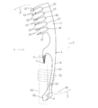
- the blade 1 according to the third embodiment shown in FIG. 7 exemplifies a hunting tool that swings sideways to capture prey that is an aquatic organism or a terrestrial organism, and is viewed from the blade 2 and one end of the blade 2.
- the tongue 3 extending in the longitudinal direction X of the blade 2 and the plurality of harpoon tips 15 projecting laterally from one side of the blade 2 form an integral plate.
- the structure is the same as that of the tongue 3 of the first embodiment for carrying out the invention, and the blade 1 is fixed to the handle 50 by the structure of the protrusion 7 and the first receiving portion 8.
- the number of harpoon tips 15 is not limited to six, but six are exemplified, the first interval portion 16 and the second interval portion 17 are exemplified as the interval portions, and the first interval portion 16 and the second interval portion 16 and the second interval portion are illustrated. An embodiment in which the portion 17 and the portion 17 are alternately adjacent to each other in the longitudinal direction X of the blade 2 is illustrated.
- the first interval portion 16 may have a shape in which the return 18 is not provided. Even in this case, it is possible to pierce the prey with a plurality of harpoon tips 15 by utilizing the centrifugal force when swinging down the blade 1. Further, the return 18 may be provided in a shape protruding from at least one of the harpoon tips 15 in the first interval portion 16 toward the side of the first interval portion 16, but the return 18 is a pair in the first interval portion 16. Since the embodiment provided in a shape protruding from the harpoon tip 15 to the side of the first interval portion 16 is illustrated, the return 18 is provided rather than being provided on at least one of the harpoon tips 15 in the first interval portion 16. When the 18 is provided on the pair of harpoon tips 15 in the first interval portion 16, the prey is less likely to escape and the prey is easier to catch.
- the second interval portion 17 is not provided with a barb.
- a protrusion 7 capable of biting into a handle 50 made of a wooden stick such as a tree branch is separated from the tongue 3 and protrudes to the rear side of the tongue 3. It is provided in.
- the protrusion 7 and the plurality of harpoon tips 15 are provided on the center line. Since the plurality of harpoon tips 15 and the protrusions 7 are arranged in a straight line, the force does not shift in the left-right direction even when a force is applied to the blade 1.
- the structure of the tongue 3 of the second form for carrying out the invention can be applied. That is, the structure may be such that the tooth portion 12 is provided on the outer surface of the protrusion 7 provided in front of the tongue 3 and the second receiving portion 13 is provided so as to face the tooth portion 12.
- the blade 1 according to the fourth embodiment shown in FIG. 8 exemplifies a spear knife that is used like a spear with a handle 50, and the blade 2 and the tongue 3 are foldably connected to each other.
- the blade 2 has a plate shape extending from one end to the other end, and has a blade 4 as a blade at the lower portion in a direction intersecting the longitudinal direction X of the blade 2, and one end of the blade 2 in the longitudinal direction X. It has a point 6 as a cutting edge.
- a protrusion 7 capable of biting into a handle 50 made of a wooden stick such as a tree branch is provided so as to separate from the tongue 3 and project to the rear side of the tongue 3. Be done.
- a first receiving portion 8 for receiving the handle 50 that bites into the protrusion 7 is provided on the rear side of the tongue 3. Therefore, the end surface of one end of the handle 50 is bitten as it is pushed from the tip side of the protrusion 7 toward the front side of the tongue 3, and the other end side of the handle 50 that bites into the protrusion 7 is the first receiver.
- the handle 50 is attached to the blade 1 by being received by the portion 8, a structure for connecting the tongue 3 and the protrusion 7 to the handle 50 is unnecessary, and the person who uses the blade 1 is suitable for his / her taste and purpose. It is easy to replace the handle 50.
- FIG. 8 shows that the other end of the blade 2 and the front end of the tongue 3 are connected by a shaft 21, the shaft 21 is the center of rotation, and the blade 4 of the blade 2 linearly projects forward from the tongue 3.
- the blade 2 and the tongue 3 have the shaft 21 in the unfolded state shown and the folded state shown in FIG. 9 in which the blade 4 of the blade 2 is overlapped on the side of the tongue 3 via the protrusion 7 of the tongue 3. It is centered on rotation and can be folded together.
- the blade 4 of the blade 2 is overlapped on the side of the tongue 3 via the protrusion 7 of the tongue 3 from the state where the handle 50 is removed from the tongue 3, and is shown in FIG. Since the blade 1 is in the folded state, the length of the blade 1 according to the fourth aspect for carrying out the invention shown in FIG. 8 in the front-rear direction as the longitudinal direction X can be shortened.
- the protrusions 7 are paired with each other with a gap in the left-right direction of the arrow Y, and the blade 2 passes through the gap between the pair of protrusions 7 facing each other.
- the central portion of one tapered male screw 9 is removed, the blade 2 passes through the removed portion, and the blade 4 faces the tongue 3. That is, a pair of protrusions 7 facing each other in the left-right direction play the role of one tapered male screw 9 in a set.
- the blade 4 and the protrusion 7 are provided in a straight line on the center line 133, even if a force in the direction of piercing the blade 1 is applied, the force does not deviate in the left-right direction, and the pair faces each other.
- the force can be transmitted to the handle 50 via the protrusion 7 of the above.
- a protrusion 7 is provided on either the left or right side of the pair of protrusions facing each other, a male screw 9 is provided on one of the provided protrusions 7, and the handle 50 is screwed onto the male screw 9 of the one protrusion 7. You may try to do it.
- the first receiving portion 8 of the tongue 3 according to the first embodiment for carrying out the invention may be provided as shown in FIG. Good. That is, the same structure as that of the first receiving unit 8 described in paragraphs 0013 to 0018 can be applied.
- the structure of the tongue 3 of the second embodiment for carrying out the invention may be applied to the blade 1 according to the fourth embodiment shown in FIG. That is, the male screw 9 of the paragraph 0049 is applied in place of the tooth portion 12, and as shown in FIG. 4, the second receiving portion 13 of the tongue 3 according to the second embodiment may be provided. That is, as shown in FIGS. 4 and 5, the second receiving portion 13 may be projected on both the left and right sides of the tongue 3, so that the second receiving portion 13 can receive the handle 50 evenly on the left and right sides. Further, as shown in FIG. 6, the second receiving portions 13 projecting on both the left and right sides of the tongue 3 are opened downward, and a downward recess 14 is formed as it goes from the side of the tongue 3 to the projecting side. The recess 14 may support the handle 50 so as not to sway from side to side.
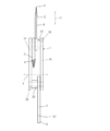
- the blade 1 according to the fifth embodiment shown in FIG. 11 exemplifies a Totoku knife, in which the blade 2, the tongue 3, and the protrusion 7 are separate from each other, and the sheath portion 30 is moved back and forth. It is separated and foldably connected.
- the blade 2 has a single plate shape extending from one end to the other end, and has a blade 4 as a blade at the lower portion in a direction intersecting the longitudinal direction X of the blade 2, and the blade 2 has a longitudinal direction X.
- a point 6 as a cutting edge is provided at one end of the.
- the tongue 3 has a single plate shape extending from one end to the other end.
- the protrusion 7 is in the shape of a single plate that is bent as if one straight line was bent at one point.
- the other end of the blade 2 and the other end of the protrusion 7 are coaxially connected to one end of the sheath 30 by a shaft 31. Then, with the shaft 31 as the center of rotation, the blade 4 of the blade 2 protrudes linearly from the sheath 30 to the front side in the unfolded state shown in FIG. 11, and the blade 4 of the blade 2 in the unfolded state is in the direction indicated by the arrow H. It is rotated so as to be in a folded state housed inside the sheath portion 30 from the front side of the sheath portion 30 via the lower side.
- the blade 2 in the deployed state is provided between the blade 2 and the sheath 30 so as not to rotate in the direction opposite to the direction indicated by the arrow H from a position linearly protruding forward from the sheath 30. It is designed to be held so as to be stopped by a stopper (not shown).
- the unfolded state shown in FIG. 11 in which one end of the protrusion 7 is bent downward from the sheath 30 and protrudes from one end to the other end of the sheath 30, and one end of the unfolded protrusion 7 is indicated by an arrow. It rotates in the direction indicated by I and is in a folded state housed inside the sheath 30 from below the sheath 30.
- the protruding portion 7 in the expanded state may be prevented from rotating or may be rotated in the direction opposite to the direction indicated by the arrow I from the position where the protruding portion 7 is bent downward from the sheath portion 30 and protrudes.
- FIG. 11 shows that one end of the tongue 3 is connected to the other end of the sheath 30 by a shaft 32, the shaft 32 is the center of rotation, and the other end of the tongue 3 linearly protrudes rearward from the sheath 30.
- the unfolded state and the other end of the unfolded tongue 3 rotate in the direction indicated by the arrow J and enter a folded state housed inside the sheath 30 from the rear side of the sheath 30 via the lower side. It has become like.
- the tongue 3 in the unfolded state may not rotate or may rotate in the direction opposite to the direction indicated by the arrow J from the position linearly protruding rearward from the sheath portion 30.
- the tongue 3 and the handle are supported by a binding member 51 such as a string or a rope.
- a binding member 51 such as a string or a rope.
- the protrusion 7 is bent downward from the sheath 30 so as not to rotate in the direction opposite to the direction indicated by the arrow I from the protruding position.
- the tongue 3 in the deployed state is stopped by a stopper (not shown) provided between the sheath portion 30 and the sheath portion 30, and the arrow J is provided from a position where the tongue 3 in the deployed state linearly protrudes to the rear side of the sheath portion 30. It is better to stop at a stopper (not shown) provided between the tongue 3 and the sheath 30 so as not to rotate in the direction opposite to the direction shown by (1) to the blade 1 of the handle 50. Installation is stable.
- the tongue 3 is accommodated inside the sheath portion 30.
- the handle 50 is attached to the blade 1
- the portion where the peripheral surface of the handle 50 and the tongue 3 come into contact with each other becomes the first receiving portion 8.
- the structure of the tongue 3 of the first embodiment of the invention may be applied, and the tongue 3 may be provided with the first receiving portion 8 projecting in the left-right lateral direction shown in FIG. 1, in which case the tongue 3 is a sheath.
- a part of the first receiving portion 8 may protrude outside the sheath portion 30 when it is housed inside the portion 30.
- One tongue 41 (not shown) and the other tongue 42 (not shown) are arranged in the gap of the two plate-shaped sheaths 30 in the lateral direction to form one tongue 3, and one tongue 41 and the other tongue are formed.
- the protrusion 7 may be arranged between the protrusion 7 and the portion 42. In such a case, when the handle 50 is attached to the blade 1, the portion where the protrusion 7 and the handle 50 contact, the portion where the pair of tongues 41 and the handle 50 contact, and the other tongue 42 and the handle 50 come into contact with each other. Since the triangle 151 in the bottom view and the triangle 152 in the back view are formed at the three contacting portions, stable coupling is possible.
- One tongue 41 and the other tongue 42 are provided in a plate shape and can be accommodated inside the sheath portion 30.
- two plate-shaped sheath portions 30 are paired with each other with a gap in the lateral direction Y.
- the blade 2, the protrusion 7, and the first spacer 34 are arranged adjacent to each other in the lateral direction Y on the side of one end of the sheath 30.
- a shaft 31 is foldably connected to two plate-shaped sheaths 30.
- the first spacer 34 is a member that secures a storage space for the tongue 3 between the blade 2 and one sheath portion 30 on the side closer to the blade 2.
- the tongue 3 and the second spacer 35 are arranged adjacent to each other in the lateral direction Y on the other end side of the sheath portion 30.
- a shaft 32 is foldably connected to two plate-shaped sheaths 30.
- the second spacer 35 is a member that secures a storage space between the blade 2 and the protrusion 7 between the tongue 3 and one sheath portion 30 on the side closer to the protrusion 7.
- the arrangement of the blade 2, the protrusion 7, and the first spacer 34 in the lateral direction Y and the arrangement of the tongue 3 and the second spacer 35 in the lateral direction Y are limited to the modes shown in FIG. is not it.
- the tooth portion 12 shown in FIG. 4 may be applied to the protrusion portion 7.
- the second receiving portion 13 may be provided on the sheath portion 30 so as to face the tooth portion 12.
- the tongue 3 of paragraphs 0032 to 0037 can be replaced with the sheath portion 30 and applied.
- FIG. 12 an example is used in which one protrusion 7 is formed into a single plate that is bent as if one straight line is bent at one place, but one straight line is at one place.
- the blade 4 and the tongue 3 may be sandwiched by using two plate-shaped protrusions 7 that are bent so as to be bent.
- the protrusions 7 are in a paired state facing each other with a gap in the lateral direction Y, and the blade 4 and the tongue 3 pass through the gap of the protrusion 7.
- FIG. 14 it is shown in the fourth embodiment for carrying out the invention by using two plate-shaped protrusions 7 which are bent so that one straight line is bent at one place.
- the structure may be similar to that of the pair of protrusions 7 facing each other in the lateral direction Y.
- the blade 1 according to the sixth embodiment shown in FIG. 13 exemplifies the Totoku machete
- the blade 2 according to the sixth embodiment shown in FIG. 13 is the blade shown in the third embodiment for carrying out the invention. It has the same structure as the structure of 2.
- the blade 1 according to the sixth embodiment shown in FIG. 13 the blade 2, the tongue 3, and the protrusion 7 are separate from each other, and the other end of the blade 2 and the protrusion 7 are separated from each other.
- the other end of the blade 2 is coaxially connected to one end of the sheath 30 by a shaft 31, the shaft 31 is the center of rotation, and the tip 15 of the blade 2 is linearly connected to the sheath 30 in the lateral direction Y on the front side.
- One end is connected to the other end of the sheath 30 by a shaft 32, the shaft 32 is the center of rotation, and the other end of the tongue 3 protrudes linearly from the sheath 30 to the rear side. Then, the other end of the tongue 3 in the unfolded state rotates in the direction indicated by the arrow J, and is in a folded state housed inside the sheath portion 30 from the rear side of the sheath portion 30 via the lower side.
- the point is the same as that of the fifth embodiment for carrying out the invention.
- the protrusion 7 may be detachable, and the description in paragraph 0024 can be applied.
- the first right protrusion 83, the first left protrusion 84, the second right protrusion 87 and the second left protrusion 88 taper toward the protruding side. It may be.
- the present invention in the first to sixth embodiments for carrying out the invention, the case of the blade 1 to which the handle is attached to the blade 2 and the tongue 3 is illustrated, but the invention is not limited to the blade 1.
- the present invention can be applied to various tools to which a handle is attached, such as tableware such as forks and spoons, fishing gear such as nets and harpoons used for fishing, and farming gear such as scoops and sickles. That is, the present invention is a handle mounting structure.
- the blade 2 corresponds to the tip member
- the tongue 3 corresponds to the mounting body
- the blade 1 corresponds to the tool.
- the attachment main body is provided on the tip member of tableware such as a fork and a spoon to serve as a tool. Further, the attachment main body is provided on the tip member of the fishing gear such as a net or a harpoon used for fishing, so that it becomes a tool. Further, the attachment main body is provided on the tip member of the agricultural tool such as a shovel or a sickle, so that it becomes a tool.
Landscapes
- Life Sciences & Earth Sciences (AREA)
- Forests & Forestry (AREA)
- Engineering & Computer Science (AREA)
- Mechanical Engineering (AREA)
- Knives (AREA)
Priority Applications (2)
| Application Number | Priority Date | Filing Date | Title |
|---|---|---|---|
| JP2021570059A JP7570700B2 (ja) | 2020-01-11 | 2021-01-05 | 刃物、道具 |
| US17/619,544 US20220379502A1 (en) | 2020-01-11 | 2021-01-05 | Knife and tool |
Applications Claiming Priority (2)
| Application Number | Priority Date | Filing Date | Title |
|---|---|---|---|
| JP2020-003289 | 2020-01-11 | ||
| JP2020003289 | 2020-01-11 |
Publications (1)
| Publication Number | Publication Date |
|---|---|
| WO2021141031A1 true WO2021141031A1 (ja) | 2021-07-15 |
Family
ID=76787968
Family Applications (1)
| Application Number | Title | Priority Date | Filing Date |
|---|---|---|---|
| PCT/JP2021/000136 Ceased WO2021141031A1 (ja) | 2020-01-11 | 2021-01-05 | 刃物、道具 |
Country Status (4)
| Country | Link |
|---|---|
| US (1) | US20220379502A1 (https=) |
| JP (1) | JP7570700B2 (https=) |
| TW (1) | TW202140229A (https=) |
| WO (1) | WO2021141031A1 (https=) |
Citations (5)
| Publication number | Priority date | Publication date | Assignee | Title |
|---|---|---|---|---|
| JPS5297858A (en) * | 1976-02-03 | 1977-08-17 | Kawashima Ind | Structure for mounting lever to core |
| JPS5419159U (https=) * | 1978-06-22 | 1979-02-07 | ||
| JPS5615677U (https=) * | 1979-07-11 | 1981-02-10 | ||
| JPS5617058U (https=) * | 1979-07-19 | 1981-02-14 | ||
| JPS62236687A (ja) * | 1986-04-03 | 1987-10-16 | 株式会社 コスモ工業 | ナイフ等の柄及びその製造方法 |
Family Cites Families (7)
| Publication number | Priority date | Publication date | Assignee | Title |
|---|---|---|---|---|
| US4716653A (en) * | 1986-09-25 | 1988-01-05 | Skyba Helmut K | Tree saw with extension attachment |
| US8905696B2 (en) * | 2012-11-26 | 2014-12-09 | Denis Lapointe | Extension fastener for portable tool |
| US9610701B1 (en) * | 2014-04-07 | 2017-04-04 | Chad Yost | Pocket hand saw with limb extender |
| US9288947B1 (en) * | 2014-07-29 | 2016-03-22 | Ronald Burnette | Folding handsaw pack-pole systems |
| US9550303B2 (en) * | 2014-10-07 | 2017-01-24 | Ruairidh Robertson | Shaving device |
| US20160194145A1 (en) * | 2015-01-02 | 2016-07-07 | Outdoor Edge Cutlery Corporation | Knife holder |
| US10213928B1 (en) * | 2016-11-10 | 2019-02-26 | Greg Smith | Combination double-sided knife and gig assembly |
-
2021
- 2021-01-05 WO PCT/JP2021/000136 patent/WO2021141031A1/ja not_active Ceased
- 2021-01-05 JP JP2021570059A patent/JP7570700B2/ja active Active
- 2021-01-05 US US17/619,544 patent/US20220379502A1/en not_active Abandoned
- 2021-01-07 TW TW110100574A patent/TW202140229A/zh unknown
Patent Citations (5)
| Publication number | Priority date | Publication date | Assignee | Title |
|---|---|---|---|---|
| JPS5297858A (en) * | 1976-02-03 | 1977-08-17 | Kawashima Ind | Structure for mounting lever to core |
| JPS5419159U (https=) * | 1978-06-22 | 1979-02-07 | ||
| JPS5615677U (https=) * | 1979-07-11 | 1981-02-10 | ||
| JPS5617058U (https=) * | 1979-07-19 | 1981-02-14 | ||
| JPS62236687A (ja) * | 1986-04-03 | 1987-10-16 | 株式会社 コスモ工業 | ナイフ等の柄及びその製造方法 |
Also Published As
| Publication number | Publication date |
|---|---|
| TW202140229A (zh) | 2021-11-01 |
| US20220379502A1 (en) | 2022-12-01 |
| JP7570700B2 (ja) | 2024-10-22 |
| JPWO2021141031A1 (https=) | 2021-07-15 |
Similar Documents
| Publication | Publication Date | Title |
|---|---|---|
| US4317284A (en) | Flatware eating utensils | |
| US5060343A (en) | Tool handle | |
| US2795923A (en) | Gardening tool | |
| US20140150329A1 (en) | Fishing Lure | |
| US5570530A (en) | Bowfishing arrowhead | |
| JP6393394B1 (ja) | ジグヘッド付ルアー及びジグヘッド | |
| US4844525A (en) | Combination barbeque fork and spatula tool | |
| WO2021141031A1 (ja) | 刃物、道具 | |
| JP6569928B1 (ja) | 包丁及び台所用品 | |
| US4768819A (en) | Combination barbeque fork and spatula tool | |
| JP7222558B2 (ja) | 釣竿のグリップ及びそれを備える釣竿 | |
| US20090100740A1 (en) | Triangular shaped cedar plug fishing lure and method | |
| US2569792A (en) | Fish lure | |
| US6935941B1 (en) | Fish pin bone remover | |
| JP3212698U (ja) | 釣り具 | |
| US20190291262A1 (en) | Tool handle | |
| US20050242597A1 (en) | Adjustable mulching tool | |
| US2194716A (en) | Hand implement | |
| JP2014217289A (ja) | ルアー仕掛け | |
| KR200426255Y1 (ko) | 칼치 털을 뽑는 포크 | |
| JP3214870U (ja) | 魚型ルアー | |
| US20060064916A1 (en) | Multi-purpose tool | |
| US11832604B2 (en) | Hunting and fishing harpoon machete | |
| JPH0722211Y2 (ja) | 切断用刃物 | |
| KR100318361B1 (ko) | 찌발사장치와 발사대 및 화살찌, 채비, 건조떡밥 등으로 구성되는 장거리찌낚시장치와 낚시방법. |
Legal Events
| Date | Code | Title | Description |
|---|---|---|---|
| 121 | Ep: the epo has been informed by wipo that ep was designated in this application |
Ref document number: 21738628 Country of ref document: EP Kind code of ref document: A1 |
|
| ENP | Entry into the national phase |
Ref document number: 2021570059 Country of ref document: JP Kind code of ref document: A |
|
| NENP | Non-entry into the national phase |
Ref country code: DE |
|
| 122 | Ep: pct application non-entry in european phase |
Ref document number: 21738628 Country of ref document: EP Kind code of ref document: A1 |