WO2021140607A1 - 情報処理装置、制御方法及び記憶媒体 - Google Patents
情報処理装置、制御方法及び記憶媒体 Download PDFInfo
- Publication number
- WO2021140607A1 WO2021140607A1 PCT/JP2020/000440 JP2020000440W WO2021140607A1 WO 2021140607 A1 WO2021140607 A1 WO 2021140607A1 JP 2020000440 W JP2020000440 W JP 2020000440W WO 2021140607 A1 WO2021140607 A1 WO 2021140607A1
- Authority
- WO
- WIPO (PCT)
- Prior art keywords
- maintenance
- information
- target device
- past
- control unit
- Prior art date
- Legal status (The legal status is an assumption and is not a legal conclusion. Google has not performed a legal analysis and makes no representation as to the accuracy of the status listed.)
- Ceased
Links
Images


Classifications
-
- G—PHYSICS
- G06—COMPUTING OR CALCULATING; COUNTING
- G06Q—INFORMATION AND COMMUNICATION TECHNOLOGY [ICT] SPECIALLY ADAPTED FOR ADMINISTRATIVE, COMMERCIAL, FINANCIAL, MANAGERIAL OR SUPERVISORY PURPOSES; SYSTEMS OR METHODS SPECIALLY ADAPTED FOR ADMINISTRATIVE, COMMERCIAL, FINANCIAL, MANAGERIAL OR SUPERVISORY PURPOSES, NOT OTHERWISE PROVIDED FOR
- G06Q10/00—Administration; Management
- G06Q10/20—Administration of product repair or maintenance
-
- G—PHYSICS
- G05—CONTROLLING; REGULATING
- G05B—CONTROL OR REGULATING SYSTEMS IN GENERAL; FUNCTIONAL ELEMENTS OF SUCH SYSTEMS; MONITORING OR TESTING ARRANGEMENTS FOR SUCH SYSTEMS OR ELEMENTS
- G05B23/00—Testing or monitoring of control systems or parts thereof
- G05B23/02—Electric testing or monitoring
- G05B23/0205—Electric testing or monitoring by means of a monitoring system capable of detecting and responding to faults
- G05B23/0208—Electric testing or monitoring by means of a monitoring system capable of detecting and responding to faults characterized by the configuration of the monitoring system
- G05B23/0213—Modular or universal configuration of the monitoring system, e.g. monitoring system having modules that may be combined to build monitoring program; monitoring system that can be applied to legacy systems; adaptable monitoring system; using different communication protocols
-
- G—PHYSICS
- G05—CONTROLLING; REGULATING
- G05B—CONTROL OR REGULATING SYSTEMS IN GENERAL; FUNCTIONAL ELEMENTS OF SUCH SYSTEMS; MONITORING OR TESTING ARRANGEMENTS FOR SUCH SYSTEMS OR ELEMENTS
- G05B23/00—Testing or monitoring of control systems or parts thereof
- G05B23/02—Electric testing or monitoring
- G05B23/0205—Electric testing or monitoring by means of a monitoring system capable of detecting and responding to faults
- G05B23/0208—Electric testing or monitoring by means of a monitoring system capable of detecting and responding to faults characterized by the configuration of the monitoring system
- G05B23/0216—Human interface functionality, e.g. monitoring system providing help to the user in the selection of tests or in its configuration
-
- G—PHYSICS
- G06—COMPUTING OR CALCULATING; COUNTING
- G06F—ELECTRIC DIGITAL DATA PROCESSING
- G06F11/00—Error detection; Error correction; Monitoring
- G06F11/30—Monitoring
-
- G—PHYSICS
- G05—CONTROLLING; REGULATING
- G05B—CONTROL OR REGULATING SYSTEMS IN GENERAL; FUNCTIONAL ELEMENTS OF SUCH SYSTEMS; MONITORING OR TESTING ARRANGEMENTS FOR SUCH SYSTEMS OR ELEMENTS
- G05B2223/00—Indexing scheme associated with group G05B23/00
- G05B2223/02—Indirect monitoring, e.g. monitoring production to detect faults of a system
Definitions
- the present invention relates to a technical field of an information processing device, a control method, and a storage medium for controlling a display related to preventive maintenance of a device.
- Patent Document 1 discloses a preventive maintenance device that calculates the difference between the predicted value of the detected value modeled in the normal state and the current detected value as the degree of abnormality.
- Patent Document 2 discloses a preventive maintenance support system that calculates the time until a device fails by predicting a transition of a sensor value.
- the preventive maintenance device described in Patent Document 1 deep domain knowledge is required to measure the maintenance timing after calculating the difference between the predicted value of the detected value modeled in the normal state and the current detected value as an abnormal value. .. Further, the devices targeted by the preventive maintenance support system described in Patent Document 2 are limited to some devices that can predict the transition of the sensor value, and should be applied to the devices that cannot predict the transition of the sensor value. There is a problem that it cannot be done.
- An object of the present invention is to provide an information processing device, a control method, and a storage medium capable of preferably presenting information on maintenance of a device to be maintained in view of the above-mentioned problems.
- One aspect of the information processing device is the information processing device, in which the first detection data indicating the past state of the maintenance target device is associated with the first maintenance information relating to the maintenance of the maintenance target device in the past state.
- a collation unit that collates the database with the second detection data indicating the current state of the maintenance target device, and a second maintenance related to maintenance according to the current state of the maintenance target device based on the collation result. It has a display control unit for displaying information on the display unit.
- One aspect of the control method is a control method executed by the information processing apparatus, in which the first detection data indicating the past state of the maintenance target device and the first maintenance information regarding the maintenance of the maintenance target device in the past state are performed.
- the database associated with the above and the second detection data indicating the current state of the maintenance target device are collated, and based on the collation result, the second maintenance related to the maintenance target device according to the current state is performed. Display maintenance information on the display.
- One aspect of the storage medium is a database in which the first detection data indicating the past state of the maintenance target device and the first maintenance information related to the maintenance of the maintenance target device in the past state are associated with each other, and the maintenance target device.
- a collation unit that collates with the second detection data indicating the current state, and a display that displays the second maintenance information related to maintenance according to the current state of the maintenance target device on the display unit based on the collation result.
- It is a storage medium that stores a program that makes a computer function as a control unit.
- the configuration of the preventive maintenance support system according to the first embodiment is shown.
- A An example of the block configuration of the information processing device is shown.
- B An example of the block configuration of the display device is shown. This is an example of a functional block of a processor of an information processing device.
- the schematic configuration of the past data generator is shown.
- A This is a first specific example of the data structure of the past data DB (DataBase).
- B This is a second specific example of the data structure of the past data DB.
- A) This is a third specific example of the data structure of the past data DB.
- B This is a fourth specific example of the data structure of the past data DB. It is a list showing the collation result.
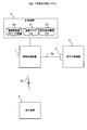
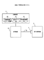
- FIG. 1 shows the configuration of the preventive maintenance support system 100 according to the first embodiment.
- the preventive maintenance support system 100 is a system that supports preventive maintenance of the maintenance target device 3, which is a device that requires maintenance such as replacement and repair of parts on a regular or irregular basis, and is a system that supports preventive maintenance of the information processing device 1 and the storage device 2. It also has a maintenance target device 3, a display device 4, and a state detection sensor 5.
- the information processing device 1 refers to the information stored in the storage device 2 and analyzes the detection signal “Sa” indicating the current state of the maintenance target device 3 supplied from the state detection sensor 5, thereby displaying a display signal. Generate "Sb”. Then, the information processing device 1 displays a screen (also referred to as a “preventive maintenance support screen”) showing information on preventive maintenance of the maintenance target device 3 on the display device 4 by transmitting the display signal Sb to the display device 4. Let me.
- the storage device 2 stores various information necessary for the information processing device 1 to generate the display signal Sb.
- the storage device 2 stores the feature converter parameter information 20, the past data DB 21, and the maintenance estimation history DB 22.
- the feature converter parameter information 20 stores parameters necessary for configuring a feature converter that generates feature data indicating a feature amount from a detection signal Sa which is time series data.
- the feature converter is a learning model trained to output feature data indicating a feature amount of the time-series data when a detection signal Sa, which is time-series data, is input.
- the learning model used for learning the feature converter may be a learning model based on a neural network, another type of learning model such as a support vector machine, or a combination thereof.
- the feature converter parameter information 20 contains the layer structure, the neuron structure of each layer, the number of filters and the filter size in each layer, and the weight of each element of each filter. Store various parameters such as. Details of the feature converter will be described later.
- the past data DB 21 is a database of past data showing the past states of the maintenance target device 3 at a plurality of time points.
- the past data includes feature data indicating the feature amount of the detection signal Sa indicating the past state of the maintenance target device 3 (also referred to as “first feature data Df1") and maintenance of the maintenance target device 3 in the past state. It is a combination with the information regarding (also referred to as "first maintenance information Im1").
- the first maintenance information Im1 includes information on the deterioration status of the maintenance target device 3 in the past state and information indicating the timing of the next maintenance of the maintenance target device 3 in the past state. Specific examples of past data will be described later.
- the maintenance estimation history DB 22 is a database that stores a history of estimation results related to maintenance estimated when the information processing device 1 generates the display signal Sb.
- the storage device 2 may be an external storage device such as a hard disk connected to or built in the information processing device 1, or may be a storage medium such as a flash memory that can be attached to and detached from the information processing device 1. .. Further, the storage device 2 may be composed of one or a plurality of server devices that perform data communication with the information processing device 1. Further, the database or the like stored in the storage device 2 may be distributed and stored by a plurality of devices or storage media.
- the display device 4 is a terminal used by a user who manages preventive maintenance of the maintenance target device 3. For example, the display device 4 transmits a display request specifying the device ID of the maintenance target device 3 to the information processing device 1, receives the display signal Sb which is the response result from the information processing device 1, and displays the display signal. Display information based on Sb. As will be described later, the display device 4 displays the preventive maintenance support screen based on the display signal Sb.
- the state detection sensor 5 is one or a plurality of sensors that detect the state of the maintenance target device 3, and transmits a detection signal Sa indicating the state of the maintenance target device 3 to the information processing device 1.
- the detection signal Sa is time-series data of one or a plurality of physical quantities (for example, voltage, current, speed, force, torque, vibration amount, etc.) necessary for detecting an abnormality in the equipment 3 to be maintained.
- the physical quantity to be detected and the type of the state detection sensor 5 used are different for each type of the maintenance target device 3.
- the state detection sensor 5 transmits the detection signal Sa to the information processing device 1 by wire communication or wireless communication.
- the information processing device 1 may be composed of a plurality of devices.
- the plurality of devices constituting the information processing device 1 exchange information necessary for executing the pre-assigned process between the plurality of devices.
- FIG. 2 (A) shows an example of the block configuration of the information processing apparatus 1.
- the information processing device 1 includes a processor 11, a memory 12, and an interface 13 as hardware.
- the processor 11, the memory 12, and the communication unit 13 are connected via the data bus 19.
- the processor 11 executes a predetermined process by executing the program stored in the memory 12.
- the processor 11 is a processor such as a CPU (Central Processing Unit) and a GPU (Graphics Processing Unit). The process executed by the processor 11 will be specifically described with reference to the functional block diagram of FIG.
- the memory 12 is composed of various memories such as a RAM (Random Access Memory), a ROM (Read Only Memory), and a non-volatile memory. Further, the memory 12 stores a program for the information processing apparatus 1 to execute a predetermined process. Further, the memory 12 is used as a working memory and temporarily stores information and the like acquired from the storage device 2. The memory 12 may function as the storage device 2. Similarly, the storage device 2 may function as the memory 12 of the information processing device 1. The program executed by the information processing device 1 may be stored in a storage medium other than the memory 12.
- the interface 13 is a communication interface for transmitting / receiving data to / from an external device such as the maintenance target device 3 and the display device 4 by wire or wirelessly based on the control of the processor 11, and corresponds to a network adapter or the like. In addition, it may be connected to an external device by a cable or the like. In this case, the interface 13 may be a communication interface for data communication with the storage device 2, or an interface compliant with USB, SATA (Serial AT Attainment), or the like for exchanging data with the storage device 2.
- USB Serial AT Attainment
- the configuration of the information processing device 1 is not limited to the configuration shown in FIG. 2 (A).
- the information processing device 1 may be connected to at least one of an input unit that receives input by a user, a display unit such as a display, or a sound output device such as a speaker, or may incorporate at least one of these.
- the information processing device 1 may be a tablet-type terminal or the like in which an input function and an output function are integrated with the main body.
- FIG. 2B shows an example of the block configuration of the display device 4.
- the display device 4 includes a processor 41, a memory 42, and an interface 43 as hardware. Each element of these display devices 4 is connected via a data bus 49.
- the processor 41 executes a predetermined process by executing the program stored in the memory 42.
- the processor 41 is a processor such as a CPU and a GPU.
- the memory 42 is composed of various types of memory such as RAM, ROM, and non-volatile memory. Further, the memory 42 stores a program for the display device 4 to execute a predetermined process. Further, the memory 42 is used as a working memory.
- the interface 43 is a communication interface for transmitting / receiving data to / from an external device such as the information processing device 1 by wire or wirelessly based on the control of the processor 41, and corresponds to a network adapter or the like. In addition, it may be connected to an external device by a cable or the like. Further, the interface 43 performs the interface operation of the input unit 44 and the display unit 45.
- the input unit 44 is, for example, a button, a switch, a touch panel, or a voice input device.
- the display unit 45 is, for example, a display or a projector.
- the input unit 44 and the display unit 45 may be external devices that are electrically connected to the display device 4 via the interface 43. Further, the interface 43 may perform an interface operation of any device other than the input unit 44 and the display unit 45.
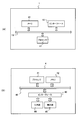
- FIG. 3 is an example of a functional block of the processor 11 of the information processing device 1.
- the processor 11 of the information processing device 1 functionally includes a feature extraction unit 31, a collation unit 32, and a display control unit 33.
- the feature extraction unit 31 acquires a detection signal Sa indicating the current state of the maintenance target device 3 from the state detection sensor 5 via the interface 13. Then, the feature extraction unit 31 extracts the feature amount from the acquired detection signal Sa by configuring the feature converter with reference to the feature converter parameter information 20, and data indicating the extracted feature amount (“second”. Feature data Df2 ”) is supplied to the collating unit 32. In this case, the feature extraction unit 31 generates the second feature data Df2 by, for example, dividing the detection signal Sa into segments having a predetermined length and inputting the divided segments into the feature converter.
- the state detection sensor 5 is composed of a plurality of sensors, the time series data of the plurality of physical quantities detected by the state detection sensor 5 in the same time zone is obtained.
- the second feature data Df2 is required to have a data amount sufficiently smaller than the segment to be feature-extracted, and is, for example, a binary string of several hundred bits.
- the second feature data Df2 is generated for the segment of the detection signal Sa detected at predetermined time intervals.
- the time interval described above may be daily or may be shorter than the segment length. In the latter case, each segment is extracted by applying a moving window (division with duplication) that allows duplication to the detection signal Sa.
- the maintenance target device 3 is a device that operates as needed (for example, a switch)
- the second feature data Df2 is obtained with respect to the segment of the detection signal Sa detected when the maintenance target device 3 is operating. Is generated.
- the second device is related to the segment of the detection signal Sa detected in the predetermined operating state.
- Feature data Df2 is generated. Since the physical quantity to be referred to in the abnormality detection (that is, the determination of the necessity of maintenance) and the extraction timing of the detection signal Sa are different for each type of the maintenance target device 3, detailed description thereof will be omitted here.
- the collation unit 32 collates the past data DB 21 with the second feature data Df2 supplied from the feature extraction unit 31, and supplies the collation result “Rc” to the display control unit 33.
- the past data DB 21 is a database of past data in which the first feature data Df1 and the first maintenance information Im1 corresponding to the states of the maintenance target devices 3 at different time points in the past are associated with each other. Therefore, the collation unit 32 calculates the degree of similarity between the second feature data Df2 and each of the first feature data Df1 registered in the past data DB 21, and sets the first feature data Df1 for a predetermined number of high-order features having a high degree of similarity.
- the collation result Rc indicating the corresponding first maintenance information Im1 and the above-mentioned similarity is output.
- the collation result Rc becomes information regarding past data indicating the past state of the maintenance target device 3 similar to the current state of the maintenance target device 3.
- the collation unit 32 calculates the distance in the feature space between the feature amount indicated by the first feature data Df1 and the feature amount indicated by the second feature data Df2 as an index of the above-mentioned similarity.
- the display control unit 33 generates information (also referred to as “second maintenance information Im2”) regarding maintenance according to the current state of the maintenance target device 3 based on the collation result Rc supplied from the collation unit 32. Then, the display control unit 33 transmits the display signal Sb based on the generated second maintenance information Im2 to the display device 4 via the interface 13.
- the second maintenance information Im2 includes information on the deterioration status based on the immediately preceding maintenance of the maintenance target device 3 in the current state, and preferably information indicating the timing of the next maintenance of the maintenance target device 3. Including further. A specific example of the second maintenance information Im2 generated by the display control unit 33 will be described later. Further, the display control unit 33 associates the generated second maintenance information Im2 with the current date (or date and time) and stores it in the maintenance estimation history DB 22.
- each component of the feature extraction unit 31, the collation unit 32, and the display control unit 33 described with reference to FIG. 4 can be realized, for example, by the processor 11 executing the program. More specifically, each component can be realized by the processor 11 executing the program stored in the memory 12. Further, each component may be realized by recording a necessary program in an arbitrary non-volatile storage medium and installing it as needed. It should be noted that each of these components is not limited to being realized by software by a program, and may be realized by a combination of hardware, firmware, software, or the like. Further, each of these components may be realized by using a user-programmable integrated circuit such as an FPGA (field-programmable gate array) or a microcomputer. In this case, this integrated circuit may be used to realize a program composed of each of the above components. As described above, each component may be realized by hardware other than the processor 11. The above is the same in other embodiments described later.
- FIG. 4 shows a schematic configuration of the past data generation device 6 that generates the past data DB 21.
- the past data generation device 6 may be an information processing device 1 or any device other than the information processing device 1 (for example, a personal computer or the like).
- the past data generation device 6 performs a past data DB 21 generation process by referring to the past detection signal DB 24 and the maintenance history DB 25 in the stage before the service is provided by the preventive maintenance support system 100.
- the past detection signal DB 24 is a database of detection signals Sa detected by the state detection sensor 5 from the maintenance target device 3 in the past.
- the past detection signal DB 24 is composed of the detection signal Sa generated at the time of maintenance or inspection of the past maintenance target device 3. It is preferable that the detection signal Sa stored in the past detection signal DB 24 is used as learning data of the feature converter in which the learned parameters are stored in the feature converter parameter information 20.
- the maintenance history DB 25 is a database that records the first maintenance information Im1 corresponding to the detection signal Sa recorded in the past detection signal DB 24.
- the past data generation device 6 functionally has a feature extraction unit 61 and an information addition unit 62.
- the feature extraction unit 61 configures a feature converter based on the feature converter parameter information 20, and inputs the detection signal Sa of the past detection signal DB 24 to the feature converter to generate the first feature data Df1.
- the information addition unit 62 registers the data in which the corresponding first maintenance information Im1 is associated with the first feature data Df1 generated by the feature extraction unit 61 as past data in the past data DB 21.
- FIG. 5A is a first specific example of the data structure of the past data DB 21.
- the maintenance target device 3 which is the target in the first specific example is a device whose standard of necessity of maintenance is the number of working days.
- the past data DB 21 according to the first specific example has each item (column) of "days", “feature amount”, “pre-maintenance elapsed days", and “next maintenance remaining days”.
- the data recorded in the item of "feature amount” corresponds to the first feature data Df1
- each of the other items in FIG. 5A, "days", “pre-maintenance elapsed days", and "next maintenance”.
- the data recorded in "remaining days” corresponds to the first maintenance information Im1.
- the "feature amount” is a feature amount indicated by the first feature data Df1 generated by the feature extraction unit 61, and is represented here by binary data as an example. “Day” indicates the detection date of the detection signal Sa used to generate the corresponding feature amount.
- the past data DB 21 may include an item of "date and time” indicating the detection date and time of the target detection signal Sa instead of "day”.
- Pre-maintenance elapsed days indicates the number of elapsed days from the maintenance date immediately before the maintenance target device 3 to the detection date of the target detection signal Sa.
- the maintenance in this case refers to maintenance such as repair and parts replacement for recovering the state of the equipment 3 to be maintained, and does not include only inspections that do not involve such maintenance.
- the “next maintenance remaining days” indicates the number of days from the detection date of the target detection signal Sa to the day when the next maintenance of the maintenance target device 3 is performed.
- the "pre-maintenance elapsed days” and “next maintenance remaining days” are examples of information on the deterioration status of the maintenance target device 3.
- the "next maintenance remaining days” is not an indispensable item. For example, when past maintenance is performed regularly, the "next maintenance remaining days” cannot be provided because the “next maintenance remaining days” can be uniquely derived from the maintenance interval and the "pre-maintenance elapsed days”. It is also good.
- the past data DB 21 is based on the first feature data Df1 based on the detection signal Sa generated every day and the maintenance performed before and after. It is composed of a record associated with the first maintenance information Im1 indicating the number of days and the like.
- FIG. 5B is a second specific example of the data structure of the past data DB 21.
- the maintenance target device 3 which is the target in the second specific example is a device (for example, a switch) that performs a predetermined operation as needed, and the standard of necessity of maintenance is a device whose number of operations is the number of operations. Then, every time the maintenance target device 3 operates a predetermined number of times (here, once), past data that becomes a record of the past data DB 21 is generated.
- the past data DB 21 according to the second specific example has each item of "date and time”, “feature amount”, "pre-maintenance operation count”, and "next maintenance remaining count”.
- the "pre-maintenance operation count” indicates the number of times the maintenance target device 3 has been operated from the immediately preceding maintenance to the time when the target detection signal Sa is detected.
- the “next maintenance remaining number” indicates the number of times the maintenance target device 3 is operated from the time when the target detection signal Sa is detected to the next maintenance of the maintenance target device 3.
- the “pre-maintenance operation count” and “next maintenance remaining count” are examples of information on the deterioration status of the maintenance target device 3.
- the past data DB 21 includes the first feature data Df1 based on the detection signal Sa detected each time the maintenance target device 3 operates, and the maintenance target device 3 based on the maintenance before and after. It is composed of a record associated with the first maintenance information Im1 indicating the number of times of operation of.
- FIG. 6A is a third specific example of the data structure of the past data DB 21.
- the maintenance target device 3 which is the target in the third specific example is a device which repeats on and off, and the standard of necessity of maintenance is the device whose actual operating time is set. Then, every time the actual operating time of the maintenance target device 3 increases by a predetermined time (here, 1 hour), past data that becomes a record of the past data DB 21 is generated.
- the past data DB 21 according to the third specific example has each item of "date and time", “feature amount”, "pre-maintenance elapsed time", and "next maintenance remaining time”.
- the "pre-maintenance elapsed time” indicates the actual operating time of the maintenance target device 3 from the time of the immediately preceding maintenance to the time of detection of the target detection signal Sa.
- the “next maintenance remaining time” indicates the actual operating time of the maintenance target device 3 from the time when the target detection signal Sa is generated to the time when the maintenance target device 3 is next maintained.
- the “pre-maintenance elapsed time” and “next maintenance remaining time” are examples of information on the deterioration status of the maintenance target device 3.
- the past data DB 21 contains the first feature data Df1 and the first maintenance information Im1 indicating the actual operation time of the maintenance target device 3 based on the maintenance performed before and after. Consists of associated records.
- FIG. 6B is a fourth specific example of the data structure of the past data DB 21.
- the maintenance target device 3 targeted in the fourth specific example may be any kind of device.
- the past data DB 21 according to the fourth specific example includes at least each item of "day”, “feature amount”, and "deterioration degree”.
- the "deterioration degree” is an index indicating the degree of deterioration of the equipment 3 to be maintained by 0% to 100%, 0% is a value indicating immediately after maintenance, and 100% requires immediate maintenance. It is a value indicating that.
- the degree of deterioration registered in each field of "degree of deterioration” may be a value input by an inspector or the like of the equipment 3 to be maintained, or may be a value calculated from other maintenance-related information. In the latter case, for example, the degree of deterioration may be calculated based on the elapsed time (number of times or actual operation time) based on the maintenance performed before and after. For example, in the case of the record of January 15, 2018 of the first specific example shown in FIG. 5 (A), since the "pre-maintenance elapsed days" is 12 and the “next maintenance remaining days” is 2, it deteriorates. The degree is "85%" ( ⁇ 12 / (12 + 2) * 100%).
- the degree of deterioration D may be calculated by the above equation with N1 as the “pre-maintenance operation count” and N2 as the “next maintenance remaining count”.
- the degree of deterioration D may be calculated by the above equation with the above-mentioned N1 as the “pre-maintenance elapsed time” and N2 as the “next maintenance remaining time”. ..
- the degree of deterioration of the maintenance target device 3 at the maintenance execution timing is recorded in the maintenance history DB 25 (for example, when the maintenance executor records the degree of deterioration of the maintenance target device 3 immediately before maintenance), information is added.
- the maintenance executor may register in the maintenance history DB 25 information having a deterioration degree of 100% corresponding to the past data immediately before or after the failure of the maintenance target device 3.
- the “deterioration degree” is an example of information regarding the deterioration status of the maintenance target device 3.
- the past data DB 21 according to the fourth specific example shown in FIG. 6B has an item of "deterioration degree" which is an index indicating the deterioration status regardless of the type of the maintenance target device 3.
- the past data DB 21 includes an item ("pre-maintenance elapsed days", etc.) indicating information on the deterioration status of the maintenance target device 3 according to the above-mentioned first to third specific examples. May be.
- FIG. 7 is a list showing the collation result Rc.
- the collating unit 32 calculates the distance in the feature space as an index of the degree of similarity between the first feature data Df1 and the second feature data Df2. Then, the collation unit 32 searches the past data DB 21 for the past data corresponding to the top five first feature data Df1 having a high degree of similarity (that is, a short distance) with the first feature data Df1, and searches the past data DB 21 for the search result. It is output as the collation result Rc.
- the list of past data shown in FIG. 7 has each item of "rank”, “day”, “distance”, “pre-maintenance elapsed days”, “next maintenance remaining days” and “deterioration degree”.
- the collating unit 32 has a “rank” for past data including information corresponding to each item of "days”, “pre-maintenance elapsed days”, “next maintenance remaining days”, and “deterioration degree”. And the information corresponding to each item of "distance” is added.
- the “rank” indicates the rank of the degree of similarity of the target past data in the past data DB 21.
- “Distance” indicates the distance between the first feature data Df1 and the second feature data Df2 of the target past data in the feature space.
- the collation unit 32 may calculate the deterioration degree based on other information included in the past data. Good.
- the collation unit 32 has the same items as the information addition unit 62 in the explanation of the data structure of the past data DB 21 according to the fourth specific example described above, that is, the "pre-maintenance elapsed days" and the "next maintenance remaining days".
- the degree of deterioration may be calculated using information or the like.
- the collation unit 32 By supplying the collation result Rc as illustrated in FIG. 7 to the display control unit 33, the collation unit 32 relates to the maintenance of the maintenance target device 3 in the past state similar to the current state of the maintenance target device 3. Information is preferably provided to the display control unit 33.
- the item “pre-maintenance elapsed days” in FIG. 7 is used.
- the “next maintenance remaining days” are the “pre-maintenance operation count” and the “next maintenance remaining number”, respectively.
- pre-maintenance elapsed days and “pre-maintenance elapsed days” and “ The “next maintenance remaining days” are the “pre-maintenance elapsed time” and the “next maintenance remaining time”, respectively.
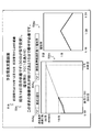
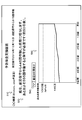
- FIG. 8 is a first display example of the preventive maintenance support screen displayed by the display device 4.
- the display control unit 33 By transmitting the display signal Sb generated via the interface 13 to the display device 4, the display control unit 33 displays the preventive maintenance support screen including the basic information 51, the maintenance-related comment 52, and the maintenance-related graph 53. Display on the display device 4.
- Basic information 51 indicates basic information of the maintenance target device 3 that is the target of preventive maintenance support.
- the display control unit 33 generates the device ID and manufacturing year of the maintenance target device 3, the date and time of the previous maintenance, and the elapsed date and time from the previous maintenance as basic information 51.
- Information about the basic information 51 (including the date of the previous maintenance) is stored in advance in, for example, a storage device 2.
- the maintenance-related comment 52 is a comment indicating the deterioration status of the maintenance target device 3 and the timing when maintenance is required when the past data of the maintenance target device 3 recorded in the past data DB 21 is used as a reference.
- the display control unit 33 uses the past data as the reference and the number of days elapsed since the previous maintenance (also referred to as “past reference elapsed days") corresponding to the current state of the maintenance target device 3 when the past data is used as a reference.
- the number of days remaining until the next maintenance of the equipment 3 to be maintained also referred to as "past standard remaining days" is included in the maintenance-related comment 52.
- the display control unit 33 aggregates the collation result Rc (specifically, the value of "pre-maintenance elapsed days") generated by the collation unit 32, so that the past standard elapsed days are 18 days (that is, the maintenance target device 3).
- the current state of is determined to be the state on the 18th day from the previous maintenance). Therefore, in this case, the display control unit 33 generates a maintenance-related comment 52 including a text sentence "Currently, it corresponds to the state of the 18th day from the previous maintenance.”
- the display control unit 33 regularly performs maintenance every 30 days in the past data of the maintenance target device 3 recorded in the past data DB 21, when the past standard elapsed days reach 30 days, Determined as the timing of maintenance.
- the display control unit 33 indicates the next maintenance remaining days indicated by the past data included in the collation result Rc.
- the average value, the weighted average value, or other representative value of the above may be determined as the number of days remaining as the past reference.
- the display control unit 33 provides information indicating the deterioration status of the maintenance target device 3 estimated based on the collation result Rc (here, the past standard elapsed days) and the timing when maintenance is required (here, the past standard remaining days). 2 It is stored in the maintenance estimation history DB 22 as maintenance information Im2. At this time, the display control unit 33 stores the second maintenance information Im2 associated with the information indicating the current date and time (or date) in the maintenance estimation history DB 22.
- the maintenance-related graph 53 is a graph showing the transition of the estimated deterioration status of the maintenance target device 3.
- the display control unit 33 extracts the second maintenance information Im2 indicating the estimation result of the deterioration status of the maintenance target device 3 for the past five days including the current date from the maintenance estimation history DB 22, and the second maintenance information Im2 is extracted from the maintenance estimation history DB 22. 2
- the maintenance-related graph 53 is displayed based on the maintenance information Im2.
- the display control unit 33 displays a line graph showing the transition of the past reference elapsed days for the past 5 days extracted from the maintenance estimation history DB 22 as the maintenance-related graph 53.
- the display control unit 33 can preferably make the user of the display device 4 grasp the transition of the past reference elapsed days.
- the display control unit 33 displays a pull-down menu type period selection field 54 for selecting a target period in the maintenance-related graph 53 in the vicinity of the maintenance-related graph 53. Then, the display control unit 33 immediately updates the display of the maintenance-related graph 53 in response to a change in the selection menu in the period selection field 54. For example, the display control unit 33 may provide "last 5 days display”, “last 10 days display”, “total period from pre-maintenance", and the like as menus that can be selected in the period selection field 54.
- the display control unit 33 averages the "pre-maintenance elapsed days" included in the past data of the upper predetermined number of high-similarity indicated by the collation result Rc.
- the value is set as the number of days that the past standard has elapsed.
- the display control unit 33 weights the "pre-maintenance elapsed days" included in the past data of the upper predetermined number having high similarity indicated by the collation result Rc.
- the average value is set as the number of days that have passed the past standard.
- the display control unit 33 sets a weight based on the degree of similarity (distance in FIG. 7) as a weight for the “pre-maintenance elapsed days”. In this case, for example, when the reciprocal of the distance is weighted with respect to the "pre-maintenance elapsed days", the past reference elapsed days calculated based on the collation result Rc shown in FIG.
- the display control unit 33 can calculate the past reference elapsed days by increasing the weight as the past data has a higher degree of similarity.
- the display control unit 33 sets a weight for the "pre-maintenance elapsed days" based on the rank (rank) of the degree of similarity. In this case, the display control unit 33 increases the weight on the corresponding "pre-maintenance elapsed days" as the rank of similarity increases. For example, the weight when the rank of similarity is 1st is "5", the weight when the rank of similarity is 2nd is “4", the weight when the rank of similarity is 3rd is "3", The weight when the rank of similarity is 4th is "2", and the weight when the rank of similarity is 5th is "1".
- the display control unit 33 also applies the averaging process based on the above-mentioned first example or the second example in the case of calculating the past standard remaining days from the "next maintenance remaining days" indicated by the collation result Rc. By doing so, the past standard remaining days can be calculated. Further, the display control unit 33 may set a representative value (for example, the median value) other than the average value (including the weighted average value) as the past reference elapsed days or the past reference remaining days.
- a representative value for example, the median value
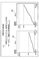
- FIG. 9 is a second display example of the preventive maintenance support screen displayed by the display device 4.
- the display control unit 33 calculates and displays the past standard remaining days in consideration of the rate of increase in the past standard elapsed days.
- the display control unit 33 displays the preventive maintenance support screen including the basic information 51A, the maintenance-related comment 52A, and the maintenance-related graph 53A. Display on the display device 4.
- the basic information 51A is the same as the basic information 51 of the first display example.
- the display control unit 33 provides preventive maintenance of maintenance-related comments 52A indicating the number of days of increase in the number of days of past standard elapsed per day (also simply referred to as “increase rate”) in addition to the number of days of past standard elapsed and the number of remaining days of past standard. Display on the support screen.
- the number of days of increase in the number of past standard elapsed days per day here, 0.64 of the actual number of days elapsed since the previous maintenance (here, 28 days) is calculated as the above-mentioned increase rate.
- the display control unit 33 refers to the maintenance estimation history DB 22, extracts the past reference elapsed days for the past predetermined days including the current date, and calculates the number of days of increase in the extracted past reference elapsed days per day. It may be calculated as the rate of increase of.
- the display control unit 33 calculates the past standard remaining days in consideration of the above-mentioned increase rate. Specifically, since the display control unit 33 has a past standard elapsed day of 18 days and the above-mentioned increase rate of 0.64, it is about 30 days for the past standard elapsed day to be a guideline for maintenance. It is determined that 19 days ( ⁇ ⁇ 30-18 ⁇ /0.64) will be required. As a result, the display control unit 33 can determine the past standard remaining days by accurately considering the actual degree of deterioration of the maintenance target device 3.
- the display control unit 33 extracts the second maintenance information Im2 indicating the estimation result of the deterioration status of the maintenance target device 3 in the entire period from the previous maintenance from the maintenance estimation history DB 22, and the second maintenance information Im2 is extracted.
- 2 Maintenance-related graph 53A is generated based on maintenance information Im2.
- the display control unit 33 shows, as the maintenance-related graph 53A, a linear graph that recursively shows the transition of the past reference elapsed days when the above-mentioned increase rate is taken into consideration, and from the time of the previous maintenance to the present time.
- the solid line shows the transition of the calculated past standard elapsed days.
- the display control unit 33 has a pull-down menu format period selection field 54Ax for selecting a target period for calculating the increase rate, and an index on the vertical axis of the graph displayed as the maintenance-related graph 53A (here, the number of days elapsed based on the past standard). ) Is provided as a graph selection field 54Ay.
- the period selection field 54Ax has the same function as the period selection field 54 of the first display example.
- the display control unit 33 calculates the number of days of increase per day of the past standard elapsed days calculated in the period specified in the period selection field 54A as the above-mentioned increase rate.
- the graph selection field 54Ay has various selectable menus such as "past reference elapsed days", “past reference elapsed days + increase rate", and "deterioration degree" in addition to "past reference elapsed days”.
- FIG. 10 shows preventive maintenance support when "last 3 times" is selected in the period selection field 54Ax and "past standard elapsed days + increase rate" is selected in the graph selection field 54Ay in the second display example of FIG. This is a screen display example.
- the display control unit 33 has a first maintenance-related graph 53Ax whose vertical axis is the past reference elapsed days and a second maintenance-related graph 53Ay whose vertical axis is the rate of increase, based on the selection result in the graph selection field 54Ay. Is provided on the preventive maintenance support screen. Further, the display control unit 33 extracts the second maintenance information Im2 for the last three times including the calculation result of this time from the maintenance estimation history DB 22 based on the selection result in the period selection field 54Ax, and extracts the second maintenance information Im2. The first maintenance-related graph 53Ax and the second maintenance-related graph 53Ay are displayed based on the above.
- the display control unit 33 has the rate of increase calculated from the transition of the past standard elapsed days of the second maintenance information Im2 for the last three times (0.70 in this case) and the past standard elapsed days calculated this time (18 days in this case). ), And the past standard remaining days (15 days in this case) is calculated. Then, the display control unit 33 updates the maintenance-related comment 52A based on the above-mentioned increase rate, the past standard elapsed days, and the past standard remaining days.
- the display control unit 33 can preferably present the past reference remaining days in consideration of the increase rate and the increase rate to the user of the display device 4.
- FIG. 11 is a third display example of the preventive maintenance support screen displayed by the display device 4.
- the display control unit 33 displays information on maintenance for each type of maintenance for the maintenance target device 3.
- the type of maintenance may be different for each part to be maintained, for example.
- the display control unit 33 selects the basic information 51B, the first maintenance-related graph 53Bx, the second maintenance-related graph 53By, and the display information.
- the preventive maintenance support screen including the column 54B is displayed on the display device 4.
- the display control unit 33 since the display control unit 33 has selected "maintenance information display for each type" in the display information selection field 54B, the display control unit 33 has selected each type of maintenance of the maintenance target device 3 (here, each of maintenance A and maintenance B). About) Display a graph related to maintenance. Specifically, the display control unit 33 provides a first maintenance-related graph 53Bx for maintenance A and a second maintenance-related graph 53By for maintenance B on the preventive maintenance support screen.
- the past data DB 21 records the past data for each type of maintenance
- the collating unit 32 has the second feature data Df2 generated based on the detection signal Sa required for each type of maintenance and the above-mentioned.
- the display control unit 33 sets the first maintenance-related graph 53Bx and the second maintenance based on the collation result Rc for each maintenance type and the second maintenance information Im2 of the maintenance estimation history DB 22 recorded in the past for each maintenance type. Generate a related graph 53By.
- the display control unit 33 may display the maintenance information of the entire maintenance target device 3 on the preventive maintenance support screen according to the selection result in the display information selection field 54B, together with the overall maintenance information of the maintenance target device 3.
- the maintenance information for each type of the maintenance target device 3 may be displayed on the preventive maintenance support screen.
- the past data DB 21 the past data for the entire maintenance of the maintenance target device 3 is recorded separately from the past data for each type of maintenance.
- the collating unit 32 collates the second feature data Df2 generated based on the detection signal Sa required for the overall inspection of the maintenance target device 3 with the above-mentioned past data, thereby performing the entire maintenance target device 3.
- the collation result Rc is generated.
- the display control unit 33 determines the total number of past reference days of the maintenance target device 3 and the like based on the overall collation result Rc of the maintenance target device 3 and the second maintenance information Im2 of the maintenance estimation history DB 22 recorded in the past.
- the maintenance-related graph shown is displayed on the preventive maintenance support screen.
- the display control unit 33 can preferably present information on maintenance for each type of the maintenance target device 3 to the user of the display device 4.
- FIG. 12 is a fourth display example of the preventive maintenance support screen displayed by the display device 4.
- the display control unit 33 displays information on maintenance of the maintenance target device 3 based on the number of operations of the maintenance target device 3 instead of the number of days.
- the display control unit 33 displays the preventive maintenance support screen including the basic information 51C, the maintenance-related comment 52C, and the maintenance-related graph 53C by transmitting the display signal Sb generated via the interface 13 to the display device 4. Displayed on the device 4.
- the display control unit 33 sets the number of operations since the previous maintenance (also referred to as “past reference number of operations”) corresponding to the current state of the maintenance target device 3 based on the past data, and the past data. The remaining number of operations (also referred to as “past standard remaining number”) until the next maintenance of the maintenance target device 3 when used as a reference is calculated. Then, the display control unit 33 generates a maintenance-related comment 52C indicating the calculated past reference operation number and the past reference remaining number. In this case, the display control unit 33 aggregates the collation result Rc (specifically, the value of the "pre-maintenance operation count") generated by the collation unit 32, so that the past reference operation count is 445 times (the actual operation count is 515). Time). Therefore, in this case, the display control unit 33 generates the maintenance-related comment 52 including the text sentence "Currently, it corresponds to the state in which the operation has been performed 445 times since the previous maintenance.”
- the collation result Rc specifically, the value of the "pre-maintenance operation
- the method of calculating the past reference operation count from the collation result Rc is the same as the method of calculating the past reference elapsed days from the collation result Rc.
- the display control unit 33 is an average value, a weighted average value, or other representative of the “pre-maintenance operation count” (see FIG. 5 (B)) included in the past data for the upper predetermined number of high-similarity. The value is calculated as the past reference number of operations.
- the display control unit 33 since the display control unit 33 periodically performs maintenance every 1000 times in the past data of the maintenance target device 3 recorded in the past data DB 21, when the past reference operation number reaches 1000 times. , Determined as the timing of maintenance. Therefore, in this case, the display control unit 33 obtains the past reference remaining number of times by subtracting the past reference operation number of 445 times from 1000 times, and displays a text sentence saying "Maintenance is required when the past reference operation number is operated 555 more times". Generate maintenance-related comments 52C including. When the collation result Rc includes information on the "next maintenance remaining number", the display control unit 33 sets the average value, the weighted average value, and other representative values of the next maintenance remaining number as the past reference remaining. It may be determined as the number of times.
- the display control unit 33 calculates the number of remaining days requiring maintenance based on the actual number of days elapsed from the previous maintenance date, the number of past reference operations calculated this time, and the number of remaining past reference, and "about 50 days later. Is included in the maintenance-related comment 52C.
- the display control unit 33 may calculate the increase rate in the same manner as in the second display example, and calculate the past reference remaining number of times in consideration of the increase rate.
- the rate of increase in this case is the number of past reference operation times per actual operation of the maintenance target device 3.
- the display control unit 33 generates the maintenance-related graph 53C based on the second maintenance information Im2 for the latest predetermined number of times stored in the maintenance estimation history DB 22.
- the display control unit 33 stores the second maintenance information Im2 including the past reference operation count and the past reference remaining count generated based on the collation result Rc in the maintenance estimation history DB 22 every day.
- the maintenance-related graph 53C is generated based on the second maintenance information Im2 for each day.
- the display control unit 33 recognizes the period targeted by the maintenance-related graph 53C (the latest 5 days in FIG. 8) based on the selection result of the period selection field 54C, and displays the maintenance-related graph 53C targeting the period. Generate.
- the display control unit 33 when the maintenance reference of the maintenance target device 3 is the number of operations, the display control unit 33 relates to the maintenance of the maintenance target device 3 based on the number of operations of the maintenance target device 3. Information can be preferably displayed.
- the display control unit 33 provides the fourth information regarding the maintenance of the maintenance target device 3 based on the actual operating time of the maintenance target device 3. It is preferable to display in the same manner as the display example.
- FIG. 13 is a fifth display example of the preventive maintenance support screen displayed by the display device 4.
- the display control unit 33 displays information on maintenance of the maintenance target device 3 based on the degree of deterioration of the maintenance target device 3 instead of the number of days.
- the display control unit 33 displays the preventive maintenance support screen including the basic information 51D, the maintenance-related comment 52D, and the maintenance-related graph 53D by transmitting the display signal Sb generated via the interface 13 to the display device 4. Displayed on the device 4.
- the display control unit 33 as maintenance-related comment 52D, has a degree of deterioration (60% here) corresponding to the current state of the equipment 3 to be maintained and the number of days remaining until maintenance (12 here) estimated from the degree of deterioration. Day) and is calculated.
- the collation result Rc includes information on the degree of deterioration of the past data for a predetermined number of high-order items having a high degree of similarity, and the display control unit 33 determines the average value, the weighted average value, or the like of the degree of deterioration. Is determined as the degree of deterioration to be displayed as the maintenance-related comment 52D.
- the display control unit 33 can, for example, refer to a table or the like showing the correspondence relationship between the degree of deterioration and the above-mentioned remaining days to determine the number of remaining days from the determined deterioration degree to the above-mentioned maintenance (past standard remaining days). decide.
- the above-mentioned table or the like is stored in the storage device 2 or the memory 12 in advance, for example.
- the display control unit 33 determines the average value of the days, the weighted average value, and other representative values as the above-mentioned remaining days. You may.
- the display control unit 33 generates the maintenance-related graph 53D based on the second maintenance information Im2 for the latest predetermined number (here, for 5 days) stored in the maintenance estimation history DB 22.
- the display control unit 33 stores the second maintenance information Im2 including the degree of deterioration determined based on the collation result Rc in the maintenance estimation history DB 22 every day, and the latest 5 days stored in the maintenance estimation history DB 22.
- a maintenance-related graph 53D is generated based on the second maintenance information Im2 of the minute.
- the display control unit 33 determines the period targeted by the maintenance-related graph 53D (the latest 5 days in FIG. 13) based on the selection result of the period selection field 54D, and displays the maintenance-related graph 53D targeting the period. Generate.
- the display control unit 33 accurately displays the necessity of maintenance based on the current state of the maintenance target device 3 by using the degree of deterioration as the maintenance standard of the maintenance target device 3. It can be recognized by the user of the device 4.
- FIG. 14 is a sixth display example of the preventive maintenance support screen displayed by the display device 4.
- the display control unit 33 displays a list of past data having a high degree of similarity indicated by the collation result Rc as information related to maintenance of the maintenance target device 3.
- the display control unit 33 displays a preventive maintenance support screen including basic information 51E, maintenance-related comment 52E, and maintenance-related list information 55E. Display on the display device 4.
- the display control unit 33 sets the past reference elapsed days corresponding to the current state of the maintenance target device 3 and the past reference remaining days, which is the number of remaining days until maintenance estimated from the past data, in the same manner as in the first display example. Calculate to. Then, the display control unit 33 displays the calculated information as a maintenance-related comment 52E on the preventive maintenance support screen.
- the display control unit 33 since the "past similarity ranking list" is selected in the display content selection field 54E, the display control unit 33 maintains a list of the top five past data having a high degree of similarity based on the collation result Rc. Related list information 55E is displayed. Here, the display control unit 33 has the same "rank”, “day”, “distance”, “pre-maintenance elapsed days”, “next maintenance remaining days”, and "deterioration degree” as in the collation result Rc shown in FIG. The maintenance-related list information 55E including each item of is displayed on the preventive maintenance support screen. Based on the selection result of the display content selection field 54E, the display control unit 33 may display a maintenance-related graph based on at least one of the first to fifth display examples on the preventive maintenance support screen.
- the display control unit 33 can present information on the maintenance of past data similar to the current state of the maintenance target device 3, and can suitably support the determination of the maintenance plan of the maintenance target device 3.
- the display control unit 33 when the display control unit 33 has past data having a high degree of similarity to be displayed in the maintenance-related list information 55E and the deterioration status is higher than a predetermined degree, the past data is the past data.
- a warning may be displayed on the preventive maintenance support screen to inform the user of the existence of.
- FIG. 15 shows a preventive maintenance support screen according to the sixth display example when there is past data in which the number of days remaining until the next maintenance is shorter than the threshold value.
- the display control unit 33 needs maintenance because the degree of deterioration of the past data corresponding to the second record of the maintenance-related list information 55E is equal to or higher than a predetermined threshold value (90%).
- Warning information 56E is displayed on the preventive maintenance support screen. Specifically, the display control unit 33 displays a text sentence as warning information 56E, "It is similar to the past data in a state of high deterioration. Please check.” On the preventive maintenance support screen. Further, the display control unit 33 highlights the second record of the maintenance-related list information 55E by the edging effect.
- the display control unit 33 preferably causes the user of the display device 4 to recognize the existence of the past data whose deterioration status is higher than a predetermined degree among the past data having a high degree of similarity. it can. Instead of determining whether or not the warning information 56E needs to be displayed based on the degree of deterioration, the display control unit 33 determines whether or not the warning information 56E needs to be displayed based on whether or not the "next maintenance remaining days" is equal to or less than a predetermined number of days. May be determined. In another example, when the number of operations is used as the criterion for the necessity of maintenance of the maintenance target device 3, the display control unit 33 sets the "next maintenance remaining number" (see FIG.
- the necessity of displaying the warning information 56E may be determined based on whether or not the warning information 56E has been displayed.
- the "next maintenance remaining time" is a predetermined time. Whether or not the warning information 56E needs to be displayed may be determined based on whether or not the following occurs. Even when the maintenance-related list information 55E is not displayed, the display control unit 33 determines whether or not the warning information 56E needs to be displayed, and displays the warning information 56E when it determines that the warning information 56E needs to be displayed. May be good.
- FIG. 16 is an example of a flowchart showing a processing procedure executed by the processor 11 of the information processing apparatus 1.
- the processor 11 repeatedly executes the process of the flowchart shown in FIG.
- the feature extraction unit 31 of the processor 11 acquires the detection signal Sa, which is time-series data of one or a plurality of physical quantities detected from the current maintenance target device 3, from the state detection sensor 5 via the interface 13 (Ste S11). Then, the feature extraction unit 31 converts the detection signal Sa acquired in step S11 into the second feature data Df2 (step S12). In this case, the feature extraction unit 31 configures the feature converter with reference to the feature converter parameter information 20, and inputs the detection signal Sa to the feature converter to acquire the second feature data Df2.
- the collation unit 32 collates the second feature data Df2 generated in step S12 with the past data which is each record of the past data DB 21 (step S13). As a result, the collation unit 32 calculates the similarity between the first feature data Df1 and the second feature data Df2 included in the past data which is each record of the past data DB 21, and the past data for a predetermined number of high similarity data. The collation result Rc corresponding to is generated.
- the display control unit 33 generates the second maintenance information Im2 based on the collation result Rc indicating a predetermined number of past data having a high degree of similarity, and associates the second maintenance information with the date and time information indicating the current date or the date and time.
- the information Im2 is stored in the maintenance estimation history DB 22 (step S14).
- the display control unit 33 displays the preventive maintenance support screen on the display device 4 based on the second maintenance information Im2 generated in step S14 (step S15).
- the display control unit 33 generates a display signal Sb based on the process described in the section of "(6) Preventive maintenance support screen ", and transmits the generated display signal Sb to the display device 4. Display the preventive maintenance support screen in 4.
- FIG. 17 shows a schematic configuration of the preventive maintenance support system 100A according to the second embodiment.
- the preventive maintenance support system 100A includes a storage device 2, a maintenance target device 3, a display device 4A, and a state detection sensor 5.
- the display device 4A has the functions of both the information processing device 1 and the display device 4 of the first embodiment.
- the hardware configuration of the display device 4A is the same as the hardware configuration of the display device 4 shown in FIG. 2 (B).
- the display device 4A refers to the feature converter parameter information 20, the past data DB 21, and the maintenance estimation history DB 22 stored in the storage device 2, and indicates the current state of the maintenance target device 3 output by the state detection sensor 5.
- the process of the flowchart shown in FIG. 16 is executed for the detection signal Sa.
- the processor 41 of the display device 4A functions as the feature extraction unit 31, the collation unit 32, and the display control unit 33 shown in FIG.
- the display device 4A displays a preventive maintenance support screen based on at least one of the first display example to the sixth display example described in the first embodiment.
- the preventive maintenance support system 100A according to the second embodiment can suitably support the preventive maintenance of the maintenance target device 3.
- FIG. 18 is a schematic configuration diagram of the information processing device 1A according to the third embodiment.
- the information processing apparatus 1A mainly includes a collating unit 32A and a display control unit 33A.
- the collation unit 32A has a database 21A that associates the first detection data indicating the past state of the maintenance target device 3 with the first maintenance information related to the maintenance of the maintenance target device in the past state, and the current state of the maintenance target device 3. Is collated with the second detection data indicating the state of.
- the database 21A is, for example, the past data DB 21 of the first embodiment, and has a data structure based on at least one of FIGS. 5 (A) to 6 (B).
- the first detection data is the first feature data Df1 indicating the feature amount of the detection signal Sa previously detected from the maintenance target device 3 in the first embodiment, and the second detection data is the present.
- This is the second feature data Df2 indicating the feature amount of the detection signal Sa detected from the maintenance target device 3 of the above.
- the collating unit 32A calculates, for example, the distance between the first feature data Df1 and the second feature data Df2 in the feature space as the degree of similarity, as in the collating unit 32 of the first embodiment. I do.
- the first detection data is the detection signal Sa of the first embodiment detected from the maintenance target device 3 in the past, and the second detection data is detected from the current maintenance target device 3. Detection signal Sa.
- the collation unit 32A uses an arbitrary method (for example, a cross-correlation function) used for confirming the similarity between the signals to determine the degree of similarity between the first detection data and the second detection data, which are time-series data. By calculating, the above-mentioned collation is performed.
- a cross-correlation function for example, a cross-correlation function
- the display control unit 33A causes the display unit 45A to display the second maintenance information regarding the maintenance according to the current state of the maintenance target device 3 based on the collation result by the collation unit 32A.
- the display control unit 33A is, for example, the display control unit 33 in the first embodiment.
- the display control unit 33A transmits a display signal including the second maintenance information Im2 to the display unit 45A to display a preventive maintenance support screen based on at least one of the first display example to the sixth display example. Display on 45A.
- the information processing device 1A can suitably display information for supporting preventive maintenance of the maintenance target device 3.
- Non-temporary computer-readable media include various types of tangible storage media.
- Examples of non-temporary computer-readable media include magnetic storage media (eg, flexible disks, magnetic tapes, hard disk drives), magneto-optical storage media (eg, magneto-optical disks), CD-ROMs (Read Only Memory), CD-Rs, It includes a CD-R / W and a semiconductor memory (for example, a mask ROM, a PROM (Programmable ROM), an EPROM (Erasable PROM), a flash ROM, and a RAM (RandomAccessMemory)).
- the program may also be supplied to the computer by various types of temporary computer readable medium.
- temporary computer-readable media include electrical, optical, and electromagnetic waves.
- the temporary computer-readable medium can supply the program to the computer via a wired communication path such as an electric wire and an optical fiber, or a wireless communication path.
- a database that associates the first detection data indicating the past state of the maintenance target device with the first maintenance information related to the maintenance of the maintenance target device in the past state, and the second detection indicating the current state of the maintenance target device.
- a collation unit that collates data with Based on the result of the collation, the display control unit that displays the second maintenance information related to the maintenance according to the current state of the maintenance target device on the display unit, and the display control unit.
- Information processing device with.
- the first maintenance information includes information on the deterioration status of the maintenance target device in the past state.
- the information processing device displays the second maintenance information including information on the deterioration status of the maintenance target device in the current state on the display unit.
- Information on the deterioration status includes the number of days elapsed from the previous maintenance, the actual operating time of the maintenance target device from the previous maintenance, the number of operations of the maintenance target device from the previous maintenance, or the degree of deterioration of the maintenance target device.
- the information processing apparatus according to Appendix 2 which is information indicating at least one of the above.
- the collation unit outputs the first maintenance information corresponding to the first detection data corresponding to the upper predetermined number of data having a high degree of similarity to the second detection data as the result of the collation.
- the information processing device according to any one of Supplementary note 1 to 3, wherein the display control unit generates the second maintenance information based on the first maintenance information output as a result of the collation.
- Appendix 5 The information processing device according to Appendix 4, wherein the display control unit generates the second maintenance information by weighting the first maintenance information based on the similarity or the order based on the similarity.
- Appendix 7 As information indicating the timing, the display control unit uses any one of the number of days until the next maintenance, the actual operating time of the maintenance target device until the next maintenance, and the number of operations of the maintenance target device until the next maintenance.
- the information processing apparatus according to Appendix 6, wherein the information indicating the above is displayed on the display unit.
- Appendix 8 The information processing device according to Appendix 6 or 7, wherein the display control unit determines the timing based on the second maintenance information generated in the past for a predetermined number of times.
- the display control unit sends the second maintenance information including the list information of the first maintenance information corresponding to the first detection data corresponding to the upper predetermined number having a high degree of similarity to the second detection data to the display unit.
- the information processing apparatus according to any one of Supplementary note 1 to 9 to be displayed.
- the display control unit has a degree of deterioration of the maintenance target device indicated by the corresponding first maintenance information among the upper predetermined number of the first detection data having a high degree of similarity to the second detection data.
- the information processing apparatus according to any one of Supplementary note 1 to 10, wherein the warning information regarding the necessity of maintenance is displayed on the display unit when the high first detection data is present.
- the first detection data is the first feature data indicating the feature amount of one or a plurality of physical quantities of time-series data indicating the past state of the maintenance target device in segment units.
- the second detection data is any one of Appendix 1 to 11, which is the second feature data indicating the feature amount of one or a plurality of physical quantities of time-series data indicating the current state of the equipment to be maintained in segment units.
- Appendix 13 Based on the feature converter used to generate the first feature data, it further has a feature extraction unit that generates the second feature data from time series data of one or a plurality of physical quantities indicating the current state of the equipment to be maintained. , The information processing apparatus according to Appendix 12.
- Appendix 14 It is a control method executed by an information processing device.
- a database that associates the first detection data indicating the past state of the maintenance target device with the first maintenance information related to the maintenance of the maintenance target device in the past state, and the second detection indicating the current state of the maintenance target device. Collate with the data, A control method for displaying on the display unit second maintenance information regarding maintenance according to the current state of the maintenance target device based on the result of the collation.
- a database that associates the first detection data indicating the past state of the maintenance target device with the first maintenance information related to the maintenance of the maintenance target device in the past state, and the second detection indicating the current state of the maintenance target device.
- a collation unit that collates data with A storage medium that stores a program that causes a computer to function as a display control unit that displays second maintenance information related to maintenance according to the current state of the maintenance target device on the display unit based on the result of the collation.
Landscapes
- Engineering & Computer Science (AREA)
- Business, Economics & Management (AREA)
- General Physics & Mathematics (AREA)
- Physics & Mathematics (AREA)
- Human Resources & Organizations (AREA)
- Theoretical Computer Science (AREA)
- Quality & Reliability (AREA)
- Economics (AREA)
- Automation & Control Theory (AREA)
- Entrepreneurship & Innovation (AREA)
- Marketing (AREA)
- Operations Research (AREA)
- Strategic Management (AREA)
- Tourism & Hospitality (AREA)
- General Business, Economics & Management (AREA)
- General Engineering & Computer Science (AREA)
- Human Computer Interaction (AREA)
- Debugging And Monitoring (AREA)
- Testing And Monitoring For Control Systems (AREA)
- Management, Administration, Business Operations System, And Electronic Commerce (AREA)
Priority Applications (3)
| Application Number | Priority Date | Filing Date | Title |
|---|---|---|---|
| US17/790,550 US20230038902A1 (en) | 2020-01-09 | 2020-01-09 | Information processing device, control method, and storage medium |
| JP2021569659A JP7582677B2 (ja) | 2020-01-09 | 2020-01-09 | 情報処理装置、制御方法及びプログラム |
| PCT/JP2020/000440 WO2021140607A1 (ja) | 2020-01-09 | 2020-01-09 | 情報処理装置、制御方法及び記憶媒体 |
Applications Claiming Priority (1)
| Application Number | Priority Date | Filing Date | Title |
|---|---|---|---|
| PCT/JP2020/000440 WO2021140607A1 (ja) | 2020-01-09 | 2020-01-09 | 情報処理装置、制御方法及び記憶媒体 |
Publications (1)
| Publication Number | Publication Date |
|---|---|
| WO2021140607A1 true WO2021140607A1 (ja) | 2021-07-15 |
Family
ID=76787767
Family Applications (1)
| Application Number | Title | Priority Date | Filing Date |
|---|---|---|---|
| PCT/JP2020/000440 Ceased WO2021140607A1 (ja) | 2020-01-09 | 2020-01-09 | 情報処理装置、制御方法及び記憶媒体 |
Country Status (3)
| Country | Link |
|---|---|
| US (1) | US20230038902A1 (https=) |
| JP (1) | JP7582677B2 (https=) |
| WO (1) | WO2021140607A1 (https=) |
Cited By (1)
| Publication number | Priority date | Publication date | Assignee | Title |
|---|---|---|---|---|
| WO2025052543A1 (ja) * | 2023-09-05 | 2025-03-13 | ファナック株式会社 | 異常検知装置、及びコンピュータ読み取り可能な記録媒体 |
Citations (7)
| Publication number | Priority date | Publication date | Assignee | Title |
|---|---|---|---|---|
| JP2011088448A (ja) * | 2011-01-13 | 2011-05-06 | Sharp Corp | 画像形成装置及び画像形成システム |
| JP2011238046A (ja) * | 2010-05-11 | 2011-11-24 | Fuji Xerox Co Ltd | 監視システム、監視装置及び監視プログラム |
| JP2013085355A (ja) * | 2011-10-07 | 2013-05-09 | Kawasaki Heavy Ind Ltd | 保守点検情報の管理方法および管理システム |
| JP2015006433A (ja) * | 2014-09-09 | 2015-01-15 | 富士フイルム株式会社 | 放射線撮影管理システム及び放射線撮影管理方法 |
| WO2016136323A1 (ja) * | 2015-02-27 | 2016-09-01 | 株式会社E.I.エンジニアリング | エネルギー予測システム、エネルギー予測方法、これを実行させるためのコンピュータプログラム及びこのプログラムを記録した記録媒体並びに運転支援システム |
| JP2018028845A (ja) * | 2016-08-19 | 2018-02-22 | 株式会社明電舎 | 異常予兆検出システムおよび異常予兆検出方法 |
| WO2018179307A1 (ja) * | 2017-03-31 | 2018-10-04 | 本田技研工業株式会社 | メンテナンス通知システムおよびその制御方法、並びにプログラム |
Family Cites Families (25)
| Publication number | Priority date | Publication date | Assignee | Title |
|---|---|---|---|---|
| JP2003076660A (ja) * | 2001-09-04 | 2003-03-14 | Fujitsu Ltd | サーバ及びクライアント・サーバシステム |
| JP2003114294A (ja) | 2001-10-04 | 2003-04-18 | Toshiba Corp | 発電プラントの監視・診断・検査・保全システム |
| JP2007102388A (ja) * | 2005-10-03 | 2007-04-19 | Hitachi Ltd | 保守支援装置,保守支援方法,保守支援システム,制御装置および制御方法 |
| US8390286B2 (en) * | 2007-05-18 | 2013-03-05 | Los Alamos National Security, Llc | Ultra-low field nuclear magnetic resonance and magnetic resonance imaging to discriminate and identify materials |
| JP4934854B2 (ja) * | 2007-08-16 | 2012-05-23 | Necフィールディング株式会社 | 部品管理システム |
| US20090063412A1 (en) * | 2007-08-30 | 2009-03-05 | Jonathan Harris | Organizing and displaying stories by themes |
| JP2009110066A (ja) * | 2007-10-26 | 2009-05-21 | Toshiba Corp | 保守カルテ表示装置および保守カルテ表示方法 |
| US8127236B2 (en) * | 2008-09-12 | 2012-02-28 | International Business Machines Corporation | Virtual universe subject matter expert assistance |
| JP5324285B2 (ja) * | 2009-03-27 | 2013-10-23 | Necパーソナルコンピュータ株式会社 | 修理部品指示システム、修理部品指示装置、方法及びプログラム |
| US9928345B2 (en) * | 2012-06-08 | 2018-03-27 | Liposciences, Inc. | Multiple-marker risk parameters predictive of conversion to diabetes |
| US9317840B2 (en) * | 2012-07-09 | 2016-04-19 | AutoVitals, Inc. | Remote service evaluation and recommendation |
| KR20140071605A (ko) * | 2012-12-04 | 2014-06-12 | 삼성전자주식회사 | 데이터 처리 방법, 센서 장치 및 사용자 단말 |
| US20140229391A1 (en) * | 2013-02-08 | 2014-08-14 | XTime, Inc. | Predictive service timeline |
| US11055450B2 (en) * | 2013-06-10 | 2021-07-06 | Abb Power Grids Switzerland Ag | Industrial asset health model update |
| US20160104124A1 (en) * | 2014-10-10 | 2016-04-14 | Caterpillar Inc. | Systems and Methods for Fleet Maintenance Management |
| JP6708203B2 (ja) * | 2015-03-17 | 2020-06-10 | 日本電気株式会社 | 情報処理装置、情報処理方法、及び、プログラム |
| US9767381B2 (en) * | 2015-09-22 | 2017-09-19 | Xerox Corporation | Similarity-based detection of prominent objects using deep CNN pooling layers as features |
| EP3596449A4 (en) * | 2017-03-14 | 2021-01-06 | University of Manitoba | DETECTION OF STRUCTURAL DEFECTS USING MACHINE LEARNING ALGORITHMS |
| US10976903B2 (en) * | 2017-09-17 | 2021-04-13 | Ge Inspection Technologies, Lp | Industrial asset intelligence |
| US10944767B2 (en) * | 2018-02-01 | 2021-03-09 | International Business Machines Corporation | Identifying artificial artifacts in input data to detect adversarial attacks |
| US20190304568A1 (en) * | 2018-03-30 | 2019-10-03 | Board Of Trustees Of Michigan State University | System and methods for machine learning for drug design and discovery |
| EP3620983B1 (en) * | 2018-09-05 | 2023-10-25 | Sartorius Stedim Data Analytics AB | Computer-implemented method, computer program product and system for data analysis |
| US20200372396A1 (en) * | 2019-05-20 | 2020-11-26 | International Business Machines Corporation | Optimal content identification for learning paths |
| US11599402B2 (en) * | 2019-08-01 | 2023-03-07 | EMC IP Holding Company LLC | Method and system for reliably forecasting storage disk failure |
| US11860903B1 (en) * | 2019-12-03 | 2024-01-02 | Ciitizen, Llc | Clustering data base on visual model |
-
2020
- 2020-01-09 JP JP2021569659A patent/JP7582677B2/ja active Active
- 2020-01-09 WO PCT/JP2020/000440 patent/WO2021140607A1/ja not_active Ceased
- 2020-01-09 US US17/790,550 patent/US20230038902A1/en not_active Abandoned
Patent Citations (7)
| Publication number | Priority date | Publication date | Assignee | Title |
|---|---|---|---|---|
| JP2011238046A (ja) * | 2010-05-11 | 2011-11-24 | Fuji Xerox Co Ltd | 監視システム、監視装置及び監視プログラム |
| JP2011088448A (ja) * | 2011-01-13 | 2011-05-06 | Sharp Corp | 画像形成装置及び画像形成システム |
| JP2013085355A (ja) * | 2011-10-07 | 2013-05-09 | Kawasaki Heavy Ind Ltd | 保守点検情報の管理方法および管理システム |
| JP2015006433A (ja) * | 2014-09-09 | 2015-01-15 | 富士フイルム株式会社 | 放射線撮影管理システム及び放射線撮影管理方法 |
| WO2016136323A1 (ja) * | 2015-02-27 | 2016-09-01 | 株式会社E.I.エンジニアリング | エネルギー予測システム、エネルギー予測方法、これを実行させるためのコンピュータプログラム及びこのプログラムを記録した記録媒体並びに運転支援システム |
| JP2018028845A (ja) * | 2016-08-19 | 2018-02-22 | 株式会社明電舎 | 異常予兆検出システムおよび異常予兆検出方法 |
| WO2018179307A1 (ja) * | 2017-03-31 | 2018-10-04 | 本田技研工業株式会社 | メンテナンス通知システムおよびその制御方法、並びにプログラム |
Cited By (1)
| Publication number | Priority date | Publication date | Assignee | Title |
|---|---|---|---|---|
| WO2025052543A1 (ja) * | 2023-09-05 | 2025-03-13 | ファナック株式会社 | 異常検知装置、及びコンピュータ読み取り可能な記録媒体 |
Also Published As
| Publication number | Publication date |
|---|---|
| US20230038902A1 (en) | 2023-02-09 |
| JPWO2021140607A1 (https=) | 2021-07-15 |
| JP7582677B2 (ja) | 2024-11-13 |
Similar Documents
| Publication | Publication Date | Title |
|---|---|---|
| US11619923B2 (en) | Digital twin management system and method | |
| JP7106847B2 (ja) | 診断装置、診断方法、プログラム、および記録媒体 | |
| JP6810097B2 (ja) | 異常検出器 | |
| WO2019012653A1 (ja) | 学習システム、分析システム、学習方法及び記憶媒体 | |
| JP6708203B2 (ja) | 情報処理装置、情報処理方法、及び、プログラム | |
| JP2019185422A (ja) | 故障予知方法、故障予知装置および故障予知プログラム | |
| WO2020066052A1 (ja) | 監視システム及び監視方法 | |
| JP7493930B2 (ja) | 情報処理方法、情報処理装置、生産システム、プログラム、記録媒体 | |
| JP2018205994A (ja) | 時系列データ分析装置、時系列データ分析方法およびコンピュータプログラム | |
| CN109146114A (zh) | 部件更换预测装置、部件更换预测系统以及部件更换预测方法 | |
| JP6922983B2 (ja) | 分析システム、分析方法及びプログラム | |
| JPWO2018073960A1 (ja) | 表示方法、表示装置、および、プログラム | |
| JP2021096639A (ja) | 制御方法、制御装置、機械設備、制御プログラム、記録媒体 | |
| CN112016689A (zh) | 信息处理装置、预测判别系统以及预测判别方法 | |
| JP2021092971A (ja) | 制御方法、制御装置、機械設備、制御プログラム、記録媒体 | |
| EP4237923B1 (en) | Assistance apparatus and method for automatically identifying failure types of a technical system | |
| WO2021140607A1 (ja) | 情報処理装置、制御方法及び記憶媒体 | |
| JP2022191680A (ja) | データ選択支援装置及びデータ選択支援方法 | |
| JP6247777B2 (ja) | 異常診断装置および異常診断方法 | |
| JP6973445B2 (ja) | 表示方法、表示装置、および、プログラム | |
| US20220147039A1 (en) | Event analytics in modular industrial plants | |
| JP2016532221A (ja) | モデル適合のための装置および方法 | |
| CN117829327A (zh) | 部件管理系统以及部件管理方法 | |
| JP6803053B1 (ja) | 情報処理装置、方法、およびプログラム | |
| JP2007164346A (ja) | 決定木変更方法、異常性判定方法およびプログラム |
Legal Events
| Date | Code | Title | Description |
|---|---|---|---|
| 121 | Ep: the epo has been informed by wipo that ep was designated in this application |
Ref document number: 20911376 Country of ref document: EP Kind code of ref document: A1 |
|
| ENP | Entry into the national phase |
Ref document number: 2021569659 Country of ref document: JP Kind code of ref document: A |
|
| NENP | Non-entry into the national phase |
Ref country code: DE |
|
| 122 | Ep: pct application non-entry in european phase |
Ref document number: 20911376 Country of ref document: EP Kind code of ref document: A1 |