WO2021131555A1 - 発酵生成物の製造方法、及びそれに使用されるセンサー装置 - Google Patents
発酵生成物の製造方法、及びそれに使用されるセンサー装置 Download PDFInfo
- Publication number
- WO2021131555A1 WO2021131555A1 PCT/JP2020/044859 JP2020044859W WO2021131555A1 WO 2021131555 A1 WO2021131555 A1 WO 2021131555A1 JP 2020044859 W JP2020044859 W JP 2020044859W WO 2021131555 A1 WO2021131555 A1 WO 2021131555A1
- Authority
- WO
- WIPO (PCT)
- Prior art keywords
- sensor
- liquid
- transmission portion
- fermenter
- cover
- Prior art date
- Legal status (The legal status is an assumption and is not a legal conclusion. Google has not performed a legal analysis and makes no representation as to the accuracy of the status listed.)
- Ceased
Links
Images


Classifications
-
- C—CHEMISTRY; METALLURGY
- C12—BIOCHEMISTRY; BEER; SPIRITS; WINE; VINEGAR; MICROBIOLOGY; ENZYMOLOGY; MUTATION OR GENETIC ENGINEERING
- C12M—APPARATUS FOR ENZYMOLOGY OR MICROBIOLOGY; APPARATUS FOR CULTURING MICROORGANISMS FOR PRODUCING BIOMASS, FOR GROWING CELLS OR FOR OBTAINING FERMENTATION OR METABOLIC PRODUCTS, i.e. BIOREACTORS OR FERMENTERS
- C12M41/00—Means for regulation, monitoring, measurement or control, e.g. flow regulation
- C12M41/30—Means for regulation, monitoring, measurement or control, e.g. flow regulation of concentration
- C12M41/32—Means for regulation, monitoring, measurement or control, e.g. flow regulation of concentration of substances in solution
-
- C—CHEMISTRY; METALLURGY
- C12—BIOCHEMISTRY; BEER; SPIRITS; WINE; VINEGAR; MICROBIOLOGY; ENZYMOLOGY; MUTATION OR GENETIC ENGINEERING
- C12M—APPARATUS FOR ENZYMOLOGY OR MICROBIOLOGY; APPARATUS FOR CULTURING MICROORGANISMS FOR PRODUCING BIOMASS, FOR GROWING CELLS OR FOR OBTAINING FERMENTATION OR METABOLIC PRODUCTS, i.e. BIOREACTORS OR FERMENTERS
- C12M27/00—Means for mixing, agitating or circulating fluids in the vessel
- C12M27/02—Stirrer or mobile mixing elements
- C12M27/04—Stirrer or mobile mixing elements with introduction of gas through the stirrer or mixing element
-
- C—CHEMISTRY; METALLURGY
- C12—BIOCHEMISTRY; BEER; SPIRITS; WINE; VINEGAR; MICROBIOLOGY; ENZYMOLOGY; MUTATION OR GENETIC ENGINEERING
- C12M—APPARATUS FOR ENZYMOLOGY OR MICROBIOLOGY; APPARATUS FOR CULTURING MICROORGANISMS FOR PRODUCING BIOMASS, FOR GROWING CELLS OR FOR OBTAINING FERMENTATION OR METABOLIC PRODUCTS, i.e. BIOREACTORS OR FERMENTERS
- C12M29/00—Means for introduction, extraction or recirculation of materials, e.g. pumps
- C12M29/04—Filters; Permeable or porous membranes or plates, e.g. dialysis
-
- C—CHEMISTRY; METALLURGY
- C12—BIOCHEMISTRY; BEER; SPIRITS; WINE; VINEGAR; MICROBIOLOGY; ENZYMOLOGY; MUTATION OR GENETIC ENGINEERING
- C12M—APPARATUS FOR ENZYMOLOGY OR MICROBIOLOGY; APPARATUS FOR CULTURING MICROORGANISMS FOR PRODUCING BIOMASS, FOR GROWING CELLS OR FOR OBTAINING FERMENTATION OR METABOLIC PRODUCTS, i.e. BIOREACTORS OR FERMENTERS
- C12M29/00—Means for introduction, extraction or recirculation of materials, e.g. pumps
- C12M29/06—Nozzles; Sprayers; Spargers; Diffusers
- C12M29/08—Air lift
-
- C—CHEMISTRY; METALLURGY
- C12—BIOCHEMISTRY; BEER; SPIRITS; WINE; VINEGAR; MICROBIOLOGY; ENZYMOLOGY; MUTATION OR GENETIC ENGINEERING
- C12M—APPARATUS FOR ENZYMOLOGY OR MICROBIOLOGY; APPARATUS FOR CULTURING MICROORGANISMS FOR PRODUCING BIOMASS, FOR GROWING CELLS OR FOR OBTAINING FERMENTATION OR METABOLIC PRODUCTS, i.e. BIOREACTORS OR FERMENTERS
- C12M41/00—Means for regulation, monitoring, measurement or control, e.g. flow regulation
- C12M41/30—Means for regulation, monitoring, measurement or control, e.g. flow regulation of concentration
-
- C—CHEMISTRY; METALLURGY
- C12—BIOCHEMISTRY; BEER; SPIRITS; WINE; VINEGAR; MICROBIOLOGY; ENZYMOLOGY; MUTATION OR GENETIC ENGINEERING
- C12P—FERMENTATION OR ENZYME-USING PROCESSES TO SYNTHESISE A DESIRED CHEMICAL COMPOUND OR COMPOSITION OR TO SEPARATE OPTICAL ISOMERS FROM A RACEMIC MIXTURE
- C12P13/00—Preparation of nitrogen-containing organic compounds
- C12P13/04—Alpha- or beta- amino acids
- C12P13/12—Methionine; Cysteine; Cystine
-
- G—PHYSICS
- G01—MEASURING; TESTING
- G01N—INVESTIGATING OR ANALYSING MATERIALS BY DETERMINING THEIR CHEMICAL OR PHYSICAL PROPERTIES
- G01N21/00—Investigating or analysing materials by the use of optical means, i.e. using sub-millimetre waves, infrared, visible or ultraviolet light
- G01N21/17—Systems in which incident light is modified in accordance with the properties of the material investigated
- G01N21/25—Colour; Spectral properties, i.e. comparison of effect of material on the light at two or more different wavelengths or wavelength bands
- G01N21/31—Investigating relative effect of material at wavelengths characteristic of specific elements or molecules, e.g. atomic absorption spectrometry
- G01N21/35—Investigating relative effect of material at wavelengths characteristic of specific elements or molecules, e.g. atomic absorption spectrometry using infrared light
- G01N21/3577—Investigating relative effect of material at wavelengths characteristic of specific elements or molecules, e.g. atomic absorption spectrometry using infrared light for analysing liquids, e.g. polluted water
-
- G—PHYSICS
- G01—MEASURING; TESTING
- G01N—INVESTIGATING OR ANALYSING MATERIALS BY DETERMINING THEIR CHEMICAL OR PHYSICAL PROPERTIES
- G01N21/00—Investigating or analysing materials by the use of optical means, i.e. using sub-millimetre waves, infrared, visible or ultraviolet light
- G01N21/17—Systems in which incident light is modified in accordance with the properties of the material investigated
- G01N21/25—Colour; Spectral properties, i.e. comparison of effect of material on the light at two or more different wavelengths or wavelength bands
- G01N21/31—Investigating relative effect of material at wavelengths characteristic of specific elements or molecules, e.g. atomic absorption spectrometry
- G01N21/35—Investigating relative effect of material at wavelengths characteristic of specific elements or molecules, e.g. atomic absorption spectrometry using infrared light
- G01N21/359—Investigating relative effect of material at wavelengths characteristic of specific elements or molecules, e.g. atomic absorption spectrometry using infrared light using near infrared light
-
- G—PHYSICS
- G01—MEASURING; TESTING
- G01N—INVESTIGATING OR ANALYSING MATERIALS BY DETERMINING THEIR CHEMICAL OR PHYSICAL PROPERTIES
- G01N21/00—Investigating or analysing materials by the use of optical means, i.e. using sub-millimetre waves, infrared, visible or ultraviolet light
- G01N21/84—Systems specially adapted for particular applications
- G01N21/85—Investigating moving fluids or granular solids
- G01N21/8507—Probe photometers, i.e. with optical measuring part dipped into fluid sample
-
- C—CHEMISTRY; METALLURGY
- C12—BIOCHEMISTRY; BEER; SPIRITS; WINE; VINEGAR; MICROBIOLOGY; ENZYMOLOGY; MUTATION OR GENETIC ENGINEERING
- C12R—INDEXING SCHEME ASSOCIATED WITH SUBCLASSES C12C - C12Q, RELATING TO MICROORGANISMS
- C12R2001/00—Microorganisms ; Processes using microorganisms
- C12R2001/01—Bacteria or Actinomycetales ; using bacteria or Actinomycetales
Definitions
- the present invention relates to a method for producing a fermentation product, and in particular, produces a fermentation product by fermenting a fermenter in which bubbles are mixed and crystals having an average particle size of 5 ⁇ m or more are produced in the liquid. , A method for producing a fermentation product, and a sensor device used therein.
- Patent Document 1 describes a method for producing L-lysine.
- the carbon source is added so as to keep the concentration of the carbon source in the culture solution at 5 g / L or less. That is, in this method, the carbon source concentration is measured by directly analyzing the carbon source concentration by sampling the culture medium in a timely manner, measuring the pH and the dissolved oxygen concentration, and detecting the carbon source deficiency state from the change. And control the feed of the medium.
- a turbidity sensor is described in Japanese Patent No. 4420168 (Patent Document 2).
- This turbidity sensor has a hollow semi-cylindrical member made of stainless steel, and a test liquid intake port and a swing valve that automatically opens and closes are provided at the lower part thereof, and a hole for removing bubbles is provided at the upper part. ing. Further, a liquid contact light measuring unit of a laser turbidity meter is arranged at the tip position inside the hollow semi-cylinder. At the time of measurement by this turbidity sensor, first, the swing valve is opened to replace the test solution inside the hollow semi-cylinder.
- the turbidity sensor described in Patent Document 2 it is necessary to wait for the detected value to stabilize after closing the swing valve, and it is difficult to perform detection in real time. Further, when the turbidity sensor is applied to a liquid in which crystals are formed in the liquid, crystals may be deposited on a moving part such as a swing valve, which may cause a failure. Further, the turbidity sensor described in Patent Document 2 requires a swing valve or the like that can be opened and closed by remote control, which complicates the structure and requires time and effort for maintenance for stable operation over a long period of time. There's a problem.
- the concentration of the fermentation product in the liquid phase exceeds the solubility, the precipitated solid
- the amount of is also required to be analyzed at the same time as the liquid phase.
- a sensor cover is provided on the sensor in order to suppress the influence of air bubbles, crystals will be deposited in the vicinity of the sensor or in the sensor cover, and it will be difficult to accurately measure the concentration of the product. For this reason, it is necessary to make the crystal concentration in the fermenter equal to the crystal concentration around the sensor and prevent the crystals from being deposited, for example, by appropriately discharging the crystals precipitated in the sensor cover.
- the present invention has a simple structure, suppresses the influence of air bubbles mixed in the liquid on the measurement result of the sensor, and prevents crystals generated in the liquid from accumulating in the vicinity of the sensor or in the sensor cover. It is an object of the present invention to provide a method for producing a fermentation product capable of measuring the characteristics of a liquid and a solid in a fermenter and performing a fermentation operation based on the characteristics, and a sensor device used therein.
- the present invention produces a fermentation product by fermenting a fermenter in which bubbles are mixed and crystals having an average particle diameter of 5 ⁇ m or more are produced in the liquid.
- a method for producing a fermentation product which is a stage of preparing a fermenter and a sensor device for measuring the characteristics of a liquid in the fermenter, a stage of charging a liquid to be fermented into the fermenter, and a fermenter.
- the sensor device measures the characteristics of the liquid in the fermenter, and the sensor device measures the characteristics of the liquid in the fermenter and adjusts the conditions of the fermentation operation based on the measurement results.
- It has a sensor and a cover body for the sensor arranged to surround the sensor, and at least a part of the lower surface of the cover body is underneath to pass at least a part of the liquid and crystals in the liquid.
- a side permeation portion is provided, and at least a part of the upper surface of the cover body is provided with an upper permeation portion through which at least a part of the liquid and crystals in the liquid passes, and the lower permeation portion and the upper permeation portion are provided with
- a large number of micropores for passing a liquid are formed, respectively, and the micropores provided in the upper transmission portion are characterized in having a size larger than the micropores provided in the lower transmission portion.
- the sensor device for measuring the characteristics of the liquid in the fermenter has a cover body arranged so as to surround the sensor. Since the cover body is provided with a lower permeation portion and an upper permeation portion through which at least a part of the liquid and crystals in the liquid pass, the liquid to be measured can constantly flow in and out of the cover body. As a result, the liquid in the cover body is constantly replaced, and the sensor arranged in the cover body can continuously measure the characteristics of the liquid in real time. Further, since the lower permeation part and the upper permeation part of the cover body pass at least a part of the crystals in the liquid, the crystals generated in the liquid are less likely to accumulate on the cover body, and maintenance such as cleaning of the cover body is performed.
- the fermentation operation can be continued for a long time without performing the fermentation operation.
- the micropores provided in the upper transmission portion have a size larger than the micropores provided in the lower transmission portion, the bubbles floating from the lower part of the cover main body can form the micropores in the lower transmission portion. It is difficult to pass through, and the invasion of air bubbles into the cover body can be effectively suppressed.
- the micropores in the upper transmission portion are formed to be larger than the micropores in the lower transmission portion, air bubbles that have entered the cover body float up in the cover body and are easily discharged through the upper transmission portion. .. As a result, it is possible to prevent air bubbles that have entered the cover body from staying in the cover body and adversely affecting the measured value of the sensor.
- the average diameter of bubbles mixed in the liquid of the fermenter is preferably 50 ⁇ m or more.
- the cover body is a crystal having an average particle diameter of 5 ⁇ m or more generated in the liquid. It is possible to suppress the invasion of air bubbles while allowing the air bubbles to permeate. As a result, a stable measured value can be obtained by the sensor.
- the average diameter of bubbles is the average value (mean volume) of the weighted code length (square length) obtained by measuring by the convergent beam reflection measurement method (FBRM). It corresponds to the so-called volume-based average value.
- the fermenter has a ventilation pipe for feeding gas into the fermenter, and the pore diameter of the outlet of the ventilation pipe is 1 ⁇ m or more.
- the pore diameter of the outlet of the ventilation pipe for feeding the gas into the fermenter is 1 ⁇ m or more, the average diameter of the bubbles mixed in the liquid of the fermenter becomes large. Therefore, the cover body can suppress the invasion of air bubbles while allowing the crystals having an average particle size of 5 ⁇ m or more generated in the liquid to permeate. As a result, a stable measured value can be obtained by the sensor.
- the fermenter has a ventilation pipe for feeding gas into the fermenter, and the volume of gas sent into the fermenter per hour through this ventilation pipe is the fermenter. It is less than twice the volume of the medium at the start of fermentation. According to the present invention configured in this way, the volume of gas sent into the fermenter per hour through the ventilation pipe is less than twice the volume of the medium at the start of fermentation, and thus the gas is placed in the fermenter.
- the gas can be dissolved in the liquid without excessively subdividing the bubbles of the gas to be sent. As a result, the invasion of air bubbles into the cover body can be easily suppressed.
- the cover body is formed in a substantially cylindrical shape, and the sensor extends in the axial direction inside the cover body.
- the cover main body is formed in a substantially cylindrical shape
- air bubbles floating from the lower side of the cover main body easily flow upward along the lower surface of the cover main body. It is possible to further suppress the invasion of air bubbles into the cover body.
- the cover body is formed in a substantially cylindrical shape, air bubbles that have entered the cover body and floated up are collected at the highest portion in the cover body, making it difficult to contact the sensor. As a result, even if air bubbles enter the cover body, the adverse effect on the measurement can be minimized.
- the lower transmissive portion is provided on the entire lower semicircular portion of the cover body having a substantially cylindrical shape
- the upper transmissive portion is provided on the entire upper semicircular portion of the cover main body.
- the cover body is formed of a thin metal plate, and the micropores provided in the lower transmission portion and the upper transmission portion are substantially circular holes provided in the thin metal plate.
- the lower transmission portion is formed by knitting a wire. Compared with the case where the side transmission portion and the upper transmission portion are formed, crystals are less likely to adhere to and deposit on the lower transmission portion and the upper transmission portion, and the maintainability of the sensor cover can be improved. Further, by forming the fine holes in the lower transmission portion and the upper transmission portion by the holes provided in the thin metal plate, it is possible to form a cover body which is less likely to be damaged than a net-like material and has high durability.
- the diameter of the micropores provided in the upper transmission portion is preferably 1 to 5 times the diameter of the micropores provided in the lower transmission portion.
- the diameter of the micropores in the upper transmission portion is set to 1 to 5 times the diameter of the micropores in the lower transmission portion.
- the diameter of the micropores provided in the lower transmission portion is preferably 540 ⁇ m to 750 ⁇ m.
- the sensor allows the inflow of liquids and crystals into the cover body. It is possible to effectively suppress the invasion of bubbles having a size that tends to adversely affect the measured value of.
- the fermentation product produced by fermenting the fermenter is cysteine, and cystine is accumulated in the fermenter by oxidizing at least a part of the cysteine.
- cysteine is produced as a fermentation product in the fermenter, and cystine is produced by oxidizing at least a part of the cysteine. Therefore, when the diameter of the micropores provided in the lower transmission portion is formed to be 540 ⁇ m to 750 ⁇ m, the crystals of cysteine and cystine in the liquid are effectively suppressed from entering the cover body. It can flow in and out, and the sensor can accurately detect the concentration of cystine.
- the cover main body is provided so as to project diagonally downward from the side wall surface of the fermenter containing the liquid, and the measurement unit of the sensor is arranged near the tip end portion of the cover main body.
- the cover main body protrudes diagonally downward from the side wall surface of the fermenter containing the liquid, air bubbles floating from below and reaching the cover main body are under the cover main body. It easily flows upward along the side surface, and intrusion into the cover body can be effectively suppressed.
- the air bubbles that have entered the cover body collect at the base end of the cover body located above, they should be moved away from the measurement part of the sensor located near the tip of the cover body to reduce the adverse effect on the measurement. Can be done.
- the present invention is a sensor device for measuring the characteristics of a liquid in a fermenter in which bubbles are mixed and crystals having an average particle diameter of 5 ⁇ m or more are generated in the liquid, and the characteristics of the liquid are measured. It has a sensor and a cover body for the sensor arranged to surround the sensor, and at least a part of the lower surface of the cover body is under the liquid and at least a part of crystals in the liquid. A side permeation portion is provided, and at least a part of the upper surface of the cover body is provided with an upper permeation part through which at least a part of the liquid and crystals in the liquid is passed, and the lower permeation part and the upper permeation part are provided. A large number of micropores for passing a liquid are formed, respectively, and the micropores provided in the upper transmission portion are characterized in having a size larger than the micropores provided in the lower transmission portion.
- a simple structure suppresses the influence of bubbles mixed in the liquid on the measurement result of the sensor and is produced in the liquid. It is possible to prevent the crystals from accumulating in the vicinity of the sensor or in the sensor cover, measure the characteristics of the liquid and the solid in the fermenter, and perform the fermentation operation based on the characteristics.
- FIG. 5 is a cross-sectional view showing an example in which a sensor device used for carrying out a method for producing a fermentation product according to an embodiment of the present invention is applied to a fermenter. It is a perspective view which shows the appearance of the cover body for a sensor provided in the sensor device by embodiment of this invention. It is a cross-sectional view which shows the state which attached the sensor device by embodiment of this invention to the side wall surface of a fermenter in an enlarged manner. It is an enlarged view which shows an example of the micropores provided on the surface of a cover body in the sensor device according to the embodiment of this invention. It is a figure which shows typically the operation of the cover for a sensor in the sensor device by embodiment of this invention.
- FIG. 1 is a cross-sectional view showing an example in which a sensor device used for carrying out a method for producing a fermentation product according to an embodiment of the present invention is applied to a fermentation tub.
- FIG. 2 is a perspective view showing the appearance of a cover body for a sensor provided in the sensor device according to the embodiment of the present invention.
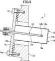
- FIG. 3 is an enlarged cross-sectional view showing a state in which the sensor device according to the embodiment of the present invention is attached to the side wall surface of the fermenter.
- the sensor device 1 is provided on the side wall surface 2a of the fermenter 2 which is a container containing a liquid, and is a culture which is a liquid contained in the fermenter 2. It is configured to measure the concentration of amino acids in the liquid L in-line. Further, a sensor is arranged inside the sensor device 1, and a signal acquired by the sensor is transmitted to the measuring instrument main body 4. Further, in the present embodiment, the fermenter 2 has a substantially cylindrical shape, and a stirrer 6 for stirring the culture solution along the central axis thereof is provided. The stirrer 6 is provided with a plurality of blades 6a for stirring the culture solution L, and by rotating these blades 6a, the culture solution L in the fermenter 2 is stirred so as to be homogeneous.
- a spurger 8 which is a ventilation tube is provided at the bottom of the fermenter 2, and the spurger 8 is provided from the supply device 8a via the spurger 8. Oxygen or air is introduced into 2. Therefore, fine bubbles of supplied oxygen and air and fine bubbles of carbon dioxide gas generated by the culturing microorganism are mixed in the culture solution L.
- the pore diameter of the outlet of the spurger 8 for discharging the gas is about 6 mm, so that bubbles having an average diameter of about 250 ⁇ m are mixed in the culture solution in the fermenter 2.
- the pore diameter for discharging the gas provided in the spurger 8 or the like is set to about 5 ⁇ m to about 36 ⁇ m, and bubbles having an average diameter of about 150 ⁇ m to about 350 ⁇ m are mixed in the culture solution in the fermenter 2.
- FAD Feine Air Diffuser
- the FAD is provided with a large number of pores having a pore diameter of about 1 ⁇ m to about 20 ⁇ m, whereby bubbles having an average diameter of about 50 ⁇ m to about 250 ⁇ m can be mixed into the culture solution.
- the sensor device 1 has a sensor cover 10 according to an embodiment of the present invention, and a sensor 12 arranged inside the sensor cover 10.
- the sensor cover 10 has a substantially cylindrical cover main body 14 and a flange portion 16 provided at the base end of the cover main body 14 and fixed to the side wall surface 2a of the fermenter 2.
- the cover main body 14 is formed of a thin stainless steel plate and has a substantially cylindrical shape with a closed tip, and is arranged so as to surround the sensor 12. Further, as will be described later, the cover body 14 is provided with a large number of micropores on the entire surface thereof, and the liquid and at least a part of the crystals in the fermenter 2 pass through these micropores in the cover body 14. Can flow into.
- the cover body can be formed in any shape other than a cylindrical shape, such as a rectangular parallelepiped. Further, the cover body can be formed of a metal other than stainless steel or a resin such as polytetrafluoroethylene, and it is preferable to form the cover body with a material that is not easily damaged by the flow of liquid due to stirring.
- the flange portion 16 is a stainless steel disk, and the cover main body 14 is fixed and integrated by welding in the center thereof. Further, the cover main body 14 is attached perpendicularly to the plate surface of the flange portion 16.
- the flange portion 16 is provided with a bolt hole 16a, and the flange portion 16 is fixed to the outside of the side wall surface 2a by the fixing bolt 18a. Further, a packing 18b is arranged between the flange portion 16 and the side wall surface 2a to ensure watertightness between the flange portion 16 and the side wall surface 2a. Further, as shown in FIG. 3, the portion on the outer side of the side wall surface 2a for fixing the flange portion 16 is formed so as to be inclined with respect to the vertical direction.
- the mounting angle of the cover main body 14 can be set to an angle that can suppress the inflow of air bubbles into the cover main body 14 and prevent the growth of various germs due to the formation of liquid pools in the vicinity of the cover main body 14.
- the angle can be set to be close to horizontal.
- the central axis of the cover body 14 is inclined by about 16 degrees with respect to the horizontal axis.
- a transmission reflection type near-infrared spectroscopic sensor (NIR sensor) is adopted as the sensor 12, and the concentration of amino acids in the culture solution L is measured by near-infrared analysis.
- NIR sensor transmission reflection type near-infrared spectroscopic sensor
- the sensor cover 10 in the present embodiment uses a NIR sensor, a spectroscopic sensor using ultraviolet rays or visible light, other optical sensors, and a convergent beam reflection measurement method (FBRM) for measuring the crystal particle size. It can be applied to various sensors such as the sensor used, an electromagnetic sensor for measuring the dielectric constant and the conductivity, and a sensor device can be configured in combination with these sensors.
- FBRM convergent beam reflection measurement method
- the sensor 12 is provided with a rod-shaped sensor probe 12a having a circular cross section, and a measuring unit 12b is provided at the tip thereof.
- the sensor probe 12a extends in the axial direction inside the cover main body 14 through an opening provided in the center of the flange portion 16 of the sensor cover 10. Further, the sensor probe 12a extends along the central axis of the cover body 14, and the measuring unit 12b provided at the tip thereof is located near the tip of the cover body 14.
- the outer diameter of the sensor probe 12a is about 20 mm
- the cover main body 14 having an outer diameter of about 60 mm surrounds the sensor probe 12a.
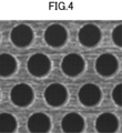
- FIG. 4 is an enlarged view showing an example of micropores provided on the surface of the cover main body 14.
- FIG. 5 is a diagram schematically showing the operation of the sensor cover.
- the cover body 14 of the sensor device 1 has a large number of micropores formed on the entire surface thereof, and at least a part of the surrounding liquid and crystals is inside the cover body 14. It is possible to flow in.
- the size of each microhole provided on the upper surface of the cover main body 14 is set to be equal to or larger than the size of each microhole provided on the lower surface. Is good. That is, the lower surface of the cover body 14 is provided with the lower transmission portion 14a through which the liquid is passed, and the upper surface is provided with the upper transmission portion 14b through which the liquid is passed, and the upper transmission portion 14b is provided.
- the micropores are formed to be the same as or larger than the micropores provided in the lower transmission portion 14a.
- the lower transmissive portion 14a is formed on the entire lower semicircle corresponding to the lower semicircle of the cover main body 14 having a circular cross section
- the upper transmissive portion 14b is formed on the entire surface of the cover main body 14. It is formed on the entire surface of the upper semicircle corresponding to the upper semicircle.
- the front end surface 14c of the cover main body 14 is also formed with a large number of micropores that are the same as the lower transmission portion 14a on the entire surface.
- the "lower surface” of the cover main body 14 means the surface on which the light hits the sensor cover 10 installed in the used state when the light is projected from vertically below, and the "upper surface”.
- “Surface” means a surface that is exposed to light when light is projected from vertically above.
- a large number of micropores are formed on the entire "lower surface” and “upper surface” of the cover main body 14, but the micropores do not necessarily have to be formed on the entire surface. It suffices if it is formed in a part.
- the tip surface 14c of the cover main body 14 is also provided with micropores, but the tip surface 14c does not have to be provided with micropores.
- substantially circular micropores are arranged in a staggered pattern in the lower transmission portion 14a and the upper transmission portion 14b. That is, each micropore is arranged so that the line connecting the centers of the three adjacent micropores forms an equilateral triangle.
- the lower transmission portion 14a and the upper transmission portion 14b are formed by etching a thin stainless steel plate to form a large number of micropores.
- Mesh Corresponds to a net formed by arranging 20 strands vertically and horizontally between 1 inch.
- the "size of micropores" of the lower transmission portion 14a and the upper transmission portion 14b means the diameter of a circular hole.
- the aperture ratio is about 44.5%, which corresponds to a net of approximately 30 #.
- the aperture ratio is about 28%, which corresponds to a net of approximately 40 #.
- the aperture ratio is about 43.6%, which corresponds to a net of approximately 60 #.
- the aperture ratio is about 28.7%, which corresponds to a net of approximately 80 #.
- the aperture ratio is about 20.5%, which corresponds to a net of approximately 150 #.
- the lower transmission portion 14a and the upper transmission portion 14b are formed by forming a large number of micropores in the thin plate, but they are formed by combining thin strands by weaving, knitting, or the like.
- the lower transmission portion 14a and the upper transmission portion 14b can also be formed of a net-like material.
- the "micropores" are formed as a space between the strands constituting the network, and the "size of the micropores” means the distance between the adjacent strands.
- the diameter of the micropores provided in the lower transmission portion 14a is set to about 180 ⁇ m to about 750 ⁇ m.
- the diameter of the micropores provided in the lower transmission portion 14a is set to about 250 ⁇ m to about 750 ⁇ m. More preferably, the diameter of the micropores provided in the lower transmission portion 14a is set to about 350 ⁇ m to about 750 ⁇ m. More preferably, the diameter of the micropores provided in the lower transmission portion 14a is set to about 540 ⁇ m to about 750 ⁇ m. That is, it is preferable that the diameter of the micropores provided in the lower permeation portion 14a is set to a size that suppresses the invasion of air bubbles in the culture solution L and allows at least a part of the crystals of the culture solution L to pass through. Further, in the lower transmission portion 14a and the upper transmission portion 14b in which a large number of micropores are formed in the thin plate, crystals are less likely to adhere and accumulate, and the maintainability of the sensor cover can be improved.
- the micropores provided in the upper transmission portion 14b are formed to have a size larger than the size of the micropores in the lower transmission portion.
- the diameter of the micropores in the upper permeation portion 14b should be set to a diameter that can sufficiently suppress the inflow of bubbles through the upper permeation portion 14b due to the downward flow of the liquid.
- the diameter of the micropores provided in the upper transmission portion 14b is set to be about 1 to about 5 times the diameter of the micropores provided in the lower transmission portion 14a.
- the operation of the sensor cover will be schematically described with reference to FIG.
- the cover main body 14 lower permeation portion 14a, upper permeation portion 14b
- the cover main body 14 is used to prevent the invasion of air bubbles. If the size of the micropores is set too fine, neither the bubble B nor the crystal C can enter the inside of the strainer. In such a case, the crystal component cannot be measured by the sensor, and accurate measurement cannot be performed.
- the size of the micropores in the cover body 14 covering the sensor is set to an appropriate size, the invasion of bubbles B can be suppressed, while the crystal C can be suppressed. At least a part of the above can penetrate the inside of the cover body 14, and the component of the crystal can be measured by the sensor.
- the lower transmission portion 14a of the cover main body 14 is formed with micropores having a small diameter, and the upper transmission portion 14b is formed with micropores larger than the lower transmission portion 14a.
- the cover body 14 is provided so as to project diagonally downward from the side wall surface 2a of the fermenter 2, so that the air bubbles blocked by the cover main body 14 can be prevented from entering. , It is easy to move diagonally upward along the lower surface of the cover body 14, and many bubbles B move upward while easily bypassing the sensor cover 10.
- the proportion of the bubbles approaching the sensor cover 10 from the lower side is high. In many cases, these intrusions are significantly suppressed by the lower permeation portion 14a. Further, also by the upper permeation portion 14b, the intrusion of some air bubbles approaching the sensor cover 10 from above or from the side due to the flow of the liquid by stirring in the fermenter completely opens the upper part of the cover. It is blocked more effectively than in the case. Further, by forming the fine pores of the upper transmission portion 14b large, the crystal C can more easily penetrate into the inside of the sensor cover 10, and the crystal component can be detected more accurately.
- cover main body 14 so as to project diagonally downward, air bubbles that have entered the cover main body 14 move upward toward the base end portion of the cover main body 14.
- the measurement unit 12b of the sensor probe 12a arranged in the cover body 14 is arranged near the tip of the cover body 14, air bubbles in the cover body 14 should be kept away from the measurement unit 12b of the sensor 12. Moved to. Therefore, the influence on the measurement of the air bubbles that have entered the cover main body 14 can be further reduced. Due to these actions, according to the sensor cover 10 of the present embodiment, the influence of air bubbles on the measurement is effectively reduced.
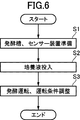
- FIG. 6 is a flowchart showing a procedure of a method for producing a fermentation product according to an embodiment of the present invention.
- FIG. 7 is a diagram showing an example in the case where the measurement is performed without using the sensor cover 10.
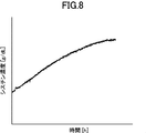
- FIG. 8 is a diagram showing an example of measurement by the sensor device 1 using an appropriate sensor cover 10.
- FIG. 9 is a diagram showing an example of a case where measurement is performed using the sensor cover 10 in which the fine holes are too fine.
- FIG. 10 is a diagram showing a state after use of various sensor covers 10.
- a fermenter 2 and a sensor device 1 for measuring the characteristics of the liquid in the fermenter 2 are prepared. Further, in the present embodiment, a spurger 8 is provided in the fermenter 2, and an air supply device 8a is connected to the spurger 8.
- the sensor cover 10 used in the sensor device 1 to be applied is selected to have micropores of an appropriate size according to the average particle size of the crystals generated in the fermenter 2. To do. Further, a plurality of sensor devices 1 may be provided for one fermenter 2 according to necessary measurement items.
- step S2 the liquid to be fermented in the fermenter 2 is put into the fermenter 2.
- cysteine is produced as a fermentation product by fermenting the culture broth L put into the fermenter 2, and at least a part of this cysteine is oxidized in the culture broth to produce the final fermentation.
- Cystine (Cys2) is produced as a substance.
- the culture solution L contains a carbon source, a nitrogen source, a sulfur source, and inorganic ions.
- the carbon source sugars such as glucose, fructose, sucrose, molasses and starch hydrolysate, and organic acids such as fumaric acid, citric acid and succinic acid can be used.
- the nitrogen source inorganic ammonium salts such as ammonium sulfate, ammonium chloride and ammonium phosphate, organic nitrogen such as soybean hydrolyzate, ammonia gas, aqueous ammonia and the like can be used.
- the sulfur source include inorganic sulfur compounds such as sulfates, sulfites, sulfides, hyposulfites, and thiosulfates.
- organic micronutrient source it is desirable to contain an appropriate amount of a required substance such as vitamin B1 or yeast extract.
- a required substance such as vitamin B1 or yeast extract.
- potassium phosphate, magnesium sulfate, iron ion, manganese ion and the like may be added in a small amount, if necessary.
- step S3 the fermentation tank 2 into which the culture solution L is charged is fermented, and the characteristics of the liquid in the fermentation tank 2 are measured by the sensor device 1.
- the culture solution L in the fermenter 2 is agitated by operating the stirrer 6, and bubbles are mixed into the culture solution L via the spurger 8 by operating the supply device 8a. Will be done.
- the average diameter of the bubbles mixed in the culture solution L by the spurger 8 is about 250 ⁇ m.
- the volume of air introduced per hour corresponds to about 0.1 to 1.2 times the volume of the medium at the start of fermentation in the fermentation tank 2.
- the volume of air sent into the fermenter 2 per hour is set to 1 to 1.2 times or less the volume of the medium at the start of fermentation in the fermenter 2, so that the bubbles are not excessively subdivided. , Air can be dissolved in the liquid.
- cystine is produced by the fermentation operation, and when the amount of cystine dissolved in the culture solution L increases, this is precipitated and cystine crystals are produced.
- the characteristics of the culture solution L during the fermentation operation are measured at any time by the sensor device 1.
- the characteristics of the culture solution L measured by the sensor device 1 include the cystine concentration [g / L], the sugar concentration [g / L] (RS), and the ammonia nitrogen concentration (RS). AN), each concentration of S 2 O 3 [g / L], turbidity (OD) of the culture solution L, and the like.
- the conditions of the fermentation operation are adjusted based on the characteristics of the culture solution L measured by the sensor device 1.
- the conditions for the fermentation operation to be adjusted include the temperature of the culture solution L, the pH of the culture solution L, the aeration amount sent through the sparger 8, the amount of the sugar solution to be added, the medium components such as phosphorus to be added, and the like. Can be mentioned.
- the adjustment of the fermentation operation conditions based on the characteristics of the measured culture solution L is carried out at any time during the fermentation operation.
- the sensor device 1 is provided with the sensor 12 (FIG. 3).
- the sensor 12 is an NIR sensor, and the light received by the sensor probe 12a is guided to the measuring instrument main body 4 (FIG. 1) via an optical fiber.
- the NIR spectrum of the guided light is acquired.
- the concentration of cystine or the like contained in the culture solution L can be estimated.
- 7 to 9 are graphs showing the temporal change of the cystine concentration estimated in this way.
- FIG. 7 is an example of measuring (estimating) the cystine concentration in the culture solution L in the fermenter 2 using the sensor 12 without attaching the sensor cover 10.
- the estimated value is large for each measurement. It is fluctuating. It is considered that this is because the bubbles mixed in the culture solution L affect the light received by the sensor probe 12a and the estimated values vary.
- FIG. 8 shows an example of an estimated value when the concentration of cystine in the culture solution L measured in the example shown in FIG. 7 was measured using the sensor device 1 provided with the sensor cover 10.
- a sensor cover 10 in which fine holes corresponding to 20 # are formed in the lower transmission portion 14a and the upper transmission portion 14b, respectively, is used.
- the estimated cystine concentration shows the same tendency as when the sensor cover 10 is not used. ..
- the fluctuation of the estimated value of the cystine concentration is smaller than that in the example shown in FIG. 7, and it can be seen that the cystine concentration is stably measured. It is considered that this is because the sensor cover 10 is provided so as to surround the sensor 12, the influence of air bubbles mixed in the culture solution L is suppressed, and the measured value is stable.
- cystine has low solubility in the culture solution L, and most of the cystine produced in the fermenter 2 precipitates and crystallizes.
- the average particle size of this crystallized cystine is 5 ⁇ m or more, but it can be seen that crystallized cystine is detected even when the sensor cover 10 is attached to the sensor 12. That is, it can be seen that the lower permeation portion 14a and the upper permeation portion 14b of the sensor cover 10 pass through at least a part of the culture solution L and the crystals in the culture solution L.
- FIG. 9 is an example in which the concentration of cystine in the culture solution L measured in the example shown in FIG. 8 was measured using the sensor cover 10 having smaller micropores than in the case of FIG.
- a sensor cover 10 in which micropores corresponding to 60 # are formed in the lower transmission portion 14a and the upper transmission portion 14b, respectively, is used.
- a stable estimated value of cystine concentration was obtained as in the example shown in FIG. 8, but the variation of the estimated value increased with the passage of time. Then, as time passes, an abnormal value appears in the estimated value, and finally the cystine concentration cannot be estimated. This is because during the fermentation operation, scaling of cystine crystals occurs on the outside of the sensor cover 10, and crystals accumulate on the inside of the sensor cover 10.
- the sensor cover 10 having micropores equivalent to 60 # has too fine micropores, and crystals precipitated from the liquid phase are produced. It is probable that the crystals could not be discharged from the cover and crystals were deposited and retained.
- the accumulation of crystals on the sensor cover 10 did not substantially occur even after the fermentation operation for a long time, and the fermentation operation for producing cystine was performed. , It can be said that the sensor cover 10 having fine holes corresponding to 20 # is suitable.
- the lower transmissive portion 14a and the upper transmissive portion 14b of the sensor cover 10 are provided with micropores of the same size, but the micropores of the upper transmissive portion 14b are provided. Can be formed to be larger than the size of the micropores in the lower transmission portion 14a.
- the micropores in the upper transmission portion 14b of the sensor cover 10 used for the measurement shown in FIG. 8 may be changed to correspond to 10 # to 15 # larger than the micropores in the lower transmission portion 14a.
- FIG. 10 is a table summarizing the results of experiments on the state of crystal deposition and the stability of the obtained measurement data when various sensor covers 10 are used.
- the conditions (2) to (5) are equivalent to 20 #, 30 #, 40 #, and 60 #.
- the case where the sensor covers 10 of the above were used respectively.
- condition (6) an experiment was also conducted in the case where the lower transmission portion 14a of the sensor cover 10 was equivalent to 80 # and the upper transmission portion 14b was equivalent to 40 #.
- the state of crystal deposition on the sensor 12 and the sensor cover 10 was observed after the fermentation operation was performed for a predetermined time under each condition.
- the adhesion of crystals to the outer surface of the sensor 12 and the sensor cover 10 is also a sensor. No retention of crystals (crystal accumulation) in the cover 10 was observed. Furthermore, there was no significant change in the estimated cystine concentration, and stable data could be measured. That is, when the sensor cover 10 is equivalent to 20 # or 30 #, the size of the micropores is sufficiently larger than the average particle size of the cystine crystals, and the cystine crystals are contained in the sensor cover 10. Can fully invade.
- the cystine crystals that have penetrated into the sensor cover 10 are detected by the sensor 12 to obtain a highly reliable estimate of the cystine concentration, and the crystals that have penetrated into the sensor cover 10 can be easily detected by the sensor cover. It flows out of 10. On the other hand, most of the bubbles mixed in the culture solution L are prevented from entering the sensor cover 10, and the adverse effect of the bubbles on the sensor 12 is suppressed.
- the fine holes of the lower transmission portion 14a are set to be equivalent to 80 #, which is finer than the condition (5).
- the fine pores of the upper transmission portion 14b are larger than those under the condition (5), so that the retention of crystals in the sensor cover 10 is less likely to occur. Therefore, by finely adjusting the size of the fine pores of the sensor cover 10 in the condition (6), the lower transmission portion 14a of the fine fine pores is used to further reduce the adverse effect of air bubbles for a long time. There is a possibility that the sensor cover 10 capable of measuring stable data over the entire range can be configured.
- the sensor cover 10 has micropores equivalent to 20 # and 30 #. Was found to be appropriate.
- FIG. 10 shows the results when cystine is produced as a fermentation product in the fermenter 2, but when another fermentation product in which crystals are produced is produced, the average particle size of the crystals produced is shown in FIG. , And the sensor cover 10 having micropores of an appropriate size may be designed according to the average diameter of the bubbles mixed in the culture solution L.
- the sensor device 1 for measuring the characteristics of the culture solution L which is a liquid in the fermenter 2
- the cover body 14 Since the cover body 14 is provided with a lower permeation portion 14a and an upper permeation portion 14b through which at least a part of the culture solution L and the crystals in the culture solution L is passed, the culture solution L to be measured is the cover body 14 It can constantly flow in and out.
- the culture solution L in the cover body 14 is constantly replaced, and the sensor 12 arranged in the cover body 14 can continuously measure the characteristics of the culture solution L containing crystals in real time.
- the lower permeation portion 14a and the upper permeation portion 14b of the cover body 14 pass at least a part of the crystals in the culture solution L, the crystals generated in the culture solution L are less likely to be deposited on the cover body 14.
- the fermentation operation can be continued for a long time without performing maintenance such as cleaning the cover body 14.
- the micropores provided in the upper transmission portion 14b have a size larger than the micropores provided in the lower transmission portion 14a, air bubbles floating from below the cover main body 14 can be removed from the lower transmission portion 14a. It is difficult to pass through the fine holes of the cover body 14, and the invasion of air bubbles into the cover body 14 can be effectively suppressed.
- the micropores of the upper transmission portion 14b are formed to be larger than the micropores of the lower transmission portion 14a, air bubbles that have entered the cover main body 14 float up in the cover main body 14 and cause the upper transmission portion 14b to rise. Easy to be discharged through. As a result, it is possible to prevent air bubbles that have entered the cover main body 14 from staying in the cover main body 14 and adversely affecting the measured value of the sensor 12.
- the average diameter of the bubbles mixed in the culture solution L of the fermentation tank 2 is 250 ⁇ m, so that the cover body 14 is produced in the solution on average. It is possible to suppress the invasion of air bubbles while allowing crystals having a particle size of 5 ⁇ m or more to permeate. As a result, a stable measured value can be obtained by the sensor 12.
- the pore diameter of the outlet of the ventilation pipe for feeding gas into the fermentation tank 2 is 6 mm, so that the average of the bubbles mixed in the culture solution L of the fermentation tank 2 is average.
- the diameter increases. Therefore, the cover body 14 can suppress the invasion of air bubbles while allowing the crystals having an average particle size of 5 ⁇ m or more generated in the culture solution L to permeate. As a result, a stable measured value can be obtained by the sensor 12.
- the volume of air which is a gas sent into the fermentation tank 2 per hour via the spudger 8 which is a ventilation tube, is the medium at the start of fermentation. Since the volume is 0.1 to 1.2 times the volume, the air can be dissolved in the culture medium L without excessively subdividing the air bubbles sent into the fermenter 2. As a result, the invasion of air bubbles into the cover body 14 can be easily suppressed.
- the cover main body 14 is formed in a substantially cylindrical shape (FIG. 2), air bubbles floating from the lower side of the cover main body 14 are formed on the cover main body 14. It easily flows upward along the lower surface, and the invasion of air bubbles into the cover body 14 can be further suppressed. Further, since the cover main body 14 is formed in a substantially cylindrical shape, air bubbles that have entered the cover main body 14 and floated up are collected at the highest portion in the cover main body 14, making it difficult to contact the sensor 12. As a result, even if air bubbles enter the cover body 14, the adverse effect on the measurement can be minimized.
- the lower permeation portion 14a and the upper permeation portion 14b are provided on the entire surfaces of the lower semicircle portion and the upper semicircle portion, respectively, so that the cover main body is provided.
- the portion through which the culture solution L and the crystals of 14 permeate can be made extremely large. As a result, the crystals that have entered the cover main body 14 are easily discharged to the outside, and the retention of the crystals in the cover main body 14 can be suppressed.
- the holes provided in the thin metal plate form fine holes in the lower permeation portion 14a and the upper permeation portion 14b (FIG. 4).
- the crystals are less likely to adhere to and accumulate on the lower transmission portion 14a and the upper transmission portion 14b, and the sensor cover 10 Maintainability can be improved.
- the fine holes of the lower transmission portion 14a and the upper transmission portion 14b by the holes provided in the thin metal plate, it is possible to form the cover body 14 which is less likely to be damaged than the net-like material and has high durability. it can.
- the diameter of the micropores in the upper permeation portion 14b is set to be larger than the diameter of the micropores in the lower permeation portion 14a, air bubbles in the cover main body 14 are set. It is possible to promote the discharge of crystals and air bubbles in the cover body while effectively suppressing the invasion, and it is possible to effectively suppress the influence of the accumulated crystals and air bubbles on the sensor 12.
- the diameter of the micropores provided in the lower transmission portion 14a is formed to be 180 ⁇ m to 750 ⁇ m, so that the liquid and crystals in the cover main body 14 are formed. It is possible to effectively suppress the invasion of air bubbles having a size that tends to adversely affect the measured value of the sensor 12 while allowing the inflow of the air bubbles.
- the cover main body 14 projects diagonally downward from the side wall surface 2a of the fermentation tank 2 containing the culture solution L (FIG. 3), so that the cover body 14 projects from below.
- the air bubbles that have floated up and reached the cover main body 14 easily flow upward along the lower side surface of the cover main body 14, and can effectively suppress the invasion into the cover main body 14. Further, since the air bubbles that have entered the cover main body 14 gather at the base end portion of the cover main body 14 located above, they move away from the measurement unit 12b of the sensor 12 arranged near the tip end portion of the cover main body 14 and give the measurement. The adverse effect can be reduced.
- cystine was produced as a fermentation product in the culture solution L in which air bubbles were mixed, but in the present invention, air bubbles are mixed and in the liquid. It can be applied to the production of any other fermentation product in which crystals are produced.
- the present invention can be applied to a fermenter in which a nucleic acid or peptide is produced.
- examples of the fermentation product include amino acids
- examples of the fermentation carbon source include, for example, sugar, monosaccharide, disaccharide and polysaccharide
- examples of the nitrogen source include ammonia and ammonium sulfate.
- Phosphorus source examples include phosphate ions
- examples of the sulfur source include thiosulfate ions.
- amino acids, nucleic acids, and peptides whose crystals are relatively easy to precipitate during fermentation include glutamic acid (Glu), tryptophan (Trp), phenylalanine (Phe), threonine (Thr), tyrosine (Tyr), and cysteine (Cys).
- cystine Cys2
- glutamic acid Gln
- aspartic acid Asp
- leu L
- isoleucine Ile
- valine Val
- inosin guanosine, and adenin.
- the concentration of the component precipitated in the liquid was measured, but the characteristics of the liquid itself such as the dielectric constant and the conductivity of the liquid are measured, and the bacterial cells in the liquid are measured. You can also do it.
- one sensor device 1 is provided in the fermenter 2, and various characteristics of the liquid are measured, but a plurality of sensor devices 1 are provided in one fermenter 2. You can also do it.
- different sensor covers can be applied to each sensor device according to the characteristics to be measured by each sensor device. For example, one sensor device 1 can measure the characteristics of the crystals precipitated, and another sensor device 1 can measure the characteristics of the components dissolved in the liquid phase.
Landscapes
- Chemical & Material Sciences (AREA)
- Life Sciences & Earth Sciences (AREA)
- Organic Chemistry (AREA)
- Health & Medical Sciences (AREA)
- Engineering & Computer Science (AREA)
- Wood Science & Technology (AREA)
- Zoology (AREA)
- Bioinformatics & Cheminformatics (AREA)
- Biochemistry (AREA)
- General Health & Medical Sciences (AREA)
- Physics & Mathematics (AREA)
- Microbiology (AREA)
- Genetics & Genomics (AREA)
- General Engineering & Computer Science (AREA)
- Biotechnology (AREA)
- Sustainable Development (AREA)
- Biomedical Technology (AREA)
- Analytical Chemistry (AREA)
- Spectroscopy & Molecular Physics (AREA)
- General Physics & Mathematics (AREA)
- Immunology (AREA)
- Pathology (AREA)
- General Chemical & Material Sciences (AREA)
- Chemical Kinetics & Catalysis (AREA)
- Apparatus Associated With Microorganisms And Enzymes (AREA)
- Investigating Or Analysing Materials By Optical Means (AREA)
- Preparation Of Compounds By Using Micro-Organisms (AREA)
Priority Applications (3)
| Application Number | Priority Date | Filing Date | Title |
|---|---|---|---|
| JP2021567124A JP7685146B2 (ja) | 2019-12-25 | 2020-12-02 | 発酵生成物の製造方法、及びそれに使用されるセンサー装置 |
| US17/807,998 US20220315966A1 (en) | 2019-12-25 | 2022-06-21 | Method for manufacturing fermentation products, and sensor device used for same |
| JP2025012634A JP2025069267A (ja) | 2019-12-25 | 2025-01-29 | 発酵生成物の製造方法、及びそれに使用されるセンサー装置 |
Applications Claiming Priority (2)
| Application Number | Priority Date | Filing Date | Title |
|---|---|---|---|
| JP2019233846 | 2019-12-25 | ||
| JP2019-233846 | 2019-12-25 |
Related Child Applications (1)
| Application Number | Title | Priority Date | Filing Date |
|---|---|---|---|
| US17/807,998 Continuation US20220315966A1 (en) | 2019-12-25 | 2022-06-21 | Method for manufacturing fermentation products, and sensor device used for same |
Publications (1)
| Publication Number | Publication Date |
|---|---|
| WO2021131555A1 true WO2021131555A1 (ja) | 2021-07-01 |
Family
ID=76575255
Family Applications (1)
| Application Number | Title | Priority Date | Filing Date |
|---|---|---|---|
| PCT/JP2020/044859 Ceased WO2021131555A1 (ja) | 2019-12-25 | 2020-12-02 | 発酵生成物の製造方法、及びそれに使用されるセンサー装置 |
Country Status (3)
| Country | Link |
|---|---|
| US (1) | US20220315966A1 (https=) |
| JP (2) | JP7685146B2 (https=) |
| WO (1) | WO2021131555A1 (https=) |
Families Citing this family (1)
| Publication number | Priority date | Publication date | Assignee | Title |
|---|---|---|---|---|
| US20190055513A1 (en) * | 2016-02-22 | 2019-02-21 | Agency For Science, Technology And Research | Cell culture medium |
Citations (5)
| Publication number | Priority date | Publication date | Assignee | Title |
|---|---|---|---|---|
| JP2006507823A (ja) * | 2002-11-28 | 2006-03-09 | ユニヴェルシタート アウトノーマ デ バルセロナ | バイオテクノロジーのハイスループットスクリーニング(hts)のための複数の自動小型バイオリアクターを備えるモジュールシステム |
| JP2009509559A (ja) * | 2005-10-04 | 2009-03-12 | アルテリス | 細胞培養方法およびそれを実施するための装置 |
| WO2012127650A1 (ja) * | 2011-03-23 | 2012-09-27 | エイブル株式会社 | 濁度測定装置 |
| JP2012200258A (ja) * | 2011-03-25 | 2012-10-22 | Finesse Solutions Inc | ポリマーバイオプロセス容器とともに用いる複合センサアセンブリ、ポリマーバイオプロセス容器とともに用いる複合アセンブリ、およびセンサまたは複合アセンブリの製造プロセス |
| JP2019180404A (ja) * | 2018-04-09 | 2019-10-24 | ショット アクチエンゲゼルシャフトSchott AG | バイオリアクタ用のセンサ保持体ならびにセンサ保持体を備えたバイオリアクタおよび生物学的材料を繁殖させるまたは培養する方法 |
Family Cites Families (5)
| Publication number | Priority date | Publication date | Assignee | Title |
|---|---|---|---|---|
| JPH053971Y2 (https=) * | 1986-05-27 | 1993-01-29 | ||
| JP5072777B2 (ja) * | 2008-09-02 | 2012-11-14 | 株式会社堀場製作所 | 試料測定装置 |
| DE102010007559B4 (de) * | 2010-02-10 | 2014-01-09 | Sartorius Stedim Biotech Gmbh | Bioreaktorbehälter mit einem optischen Schaumsensor |
| JP6989958B2 (ja) * | 2016-10-28 | 2022-02-03 | 国立大学法人京都大学 | 嫌気性細菌などの細菌と上皮細胞との共培養システム |
| CN209584232U (zh) * | 2019-02-01 | 2019-11-05 | 内蒙古柯宏生物科技有限公司 | 微生物发酵罐 |
-
2020
- 2020-12-02 JP JP2021567124A patent/JP7685146B2/ja active Active
- 2020-12-02 WO PCT/JP2020/044859 patent/WO2021131555A1/ja not_active Ceased
-
2022
- 2022-06-21 US US17/807,998 patent/US20220315966A1/en active Pending
-
2025
- 2025-01-29 JP JP2025012634A patent/JP2025069267A/ja active Pending
Patent Citations (5)
| Publication number | Priority date | Publication date | Assignee | Title |
|---|---|---|---|---|
| JP2006507823A (ja) * | 2002-11-28 | 2006-03-09 | ユニヴェルシタート アウトノーマ デ バルセロナ | バイオテクノロジーのハイスループットスクリーニング(hts)のための複数の自動小型バイオリアクターを備えるモジュールシステム |
| JP2009509559A (ja) * | 2005-10-04 | 2009-03-12 | アルテリス | 細胞培養方法およびそれを実施するための装置 |
| WO2012127650A1 (ja) * | 2011-03-23 | 2012-09-27 | エイブル株式会社 | 濁度測定装置 |
| JP2012200258A (ja) * | 2011-03-25 | 2012-10-22 | Finesse Solutions Inc | ポリマーバイオプロセス容器とともに用いる複合センサアセンブリ、ポリマーバイオプロセス容器とともに用いる複合アセンブリ、およびセンサまたは複合アセンブリの製造プロセス |
| JP2019180404A (ja) * | 2018-04-09 | 2019-10-24 | ショット アクチエンゲゼルシャフトSchott AG | バイオリアクタ用のセンサ保持体ならびにセンサ保持体を備えたバイオリアクタおよび生物学的材料を繁殖させるまたは培養する方法 |
Also Published As
| Publication number | Publication date |
|---|---|
| US20220315966A1 (en) | 2022-10-06 |
| JP7685146B2 (ja) | 2025-05-29 |
| JPWO2021131555A1 (https=) | 2021-07-01 |
| JP2025069267A (ja) | 2025-04-30 |
Similar Documents
| Publication | Publication Date | Title |
|---|---|---|
| JP2023184548A (ja) | センサー用カバー及びそれを備えたセンサー装置、及び液体の特性の測定方法、通気培養における代謝生産物の製造方法 | |
| CN111252914B (zh) | 一种无磷缓蚀阻垢剂及制备装置及制备方法 | |
| Rhiel et al. | Real‐time in situ monitoring of freely suspended and immobilized cell cultures based on mid‐infrared spectroscopic measurements | |
| US10748278B2 (en) | Organism evaluation system and method of use | |
| van Dijk et al. | Impacts of pH and [CO32−] on the incorporation of Zn in foraminiferal calcite | |
| US20090104594A1 (en) | Bioreactor Process Control System and Method | |
| JP2025069267A (ja) | 発酵生成物の製造方法、及びそれに使用されるセンサー装置 | |
| US11137354B2 (en) | Methods and apparatus for reducing measurement artifacts of sensor measurements | |
| CN109743944A (zh) | 一种日光温室水肥一体智能调控系统及其方法 | |
| Deshpande et al. | Microplates with integrated oxygen sensing for medium optimization in animal cell culture | |
| NO883935L (no) | Fremgangsmaate for fremstilling av en mikroorganismecellemasse, samt maaleutstyr for anvendelse ved fremgangsmaaten. | |
| CN109239141A (zh) | 一种基于醇类气体浓度在线检测的发酵过程反馈补料控制装置及方法 | |
| US7800757B2 (en) | System and method for the spectroscopic determination of the components and concentrations of pumpable organic compounds | |
| US11391630B2 (en) | Spectrum measuring device and spectrum measuring method | |
| EP1697723B1 (en) | A measuring cell | |
| CN212834133U (zh) | 一种电镀生产中镀液浓度调节的自动补加装置 | |
| KR102083327B1 (ko) | 측정 정밀도를 높이기 위한 검사용 유로 구조 | |
| CN106434291A (zh) | 一种不间断培养生产赖氨酸的装置和方法 | |
| EP4712764A1 (en) | A method and apparatus for crop health monitoring and nutrient supply analysis for crop cultivation | |
| KR101897373B1 (ko) | pH 자동 조정 장치 | |
| EP4119936A1 (en) | Calibration liquid for water quality measurement device, calibration-liquid-filled container for water quality measurement device, and calibration method using calibration liquid for water quality measurement device | |
| CN108445160B (zh) | 一种用于海洋生物生理生态学研究的实验装置 | |
| US20170050226A1 (en) | Self-cleaning monitoring system for biomass processing | |
| CN208297227U (zh) | 一种无障碍搅拌设备 | |
| US10132749B1 (en) | System and method for simultaneous measurement of turbidity and chlorine content of a sample of a liquid |
Legal Events
| Date | Code | Title | Description |
|---|---|---|---|
| 121 | Ep: the epo has been informed by wipo that ep was designated in this application |
Ref document number: 20905680 Country of ref document: EP Kind code of ref document: A1 |
|
| ENP | Entry into the national phase |
Ref document number: 2021567124 Country of ref document: JP Kind code of ref document: A |
|
| NENP | Non-entry into the national phase |
Ref country code: DE |
|
| 122 | Ep: pct application non-entry in european phase |
Ref document number: 20905680 Country of ref document: EP Kind code of ref document: A1 |