WO2021129099A1 - Half-nut assembly - Google Patents
Half-nut assembly Download PDFInfo
- Publication number
- WO2021129099A1 WO2021129099A1 PCT/CN2020/123040 CN2020123040W WO2021129099A1 WO 2021129099 A1 WO2021129099 A1 WO 2021129099A1 CN 2020123040 W CN2020123040 W CN 2020123040W WO 2021129099 A1 WO2021129099 A1 WO 2021129099A1
- Authority
- WO
- WIPO (PCT)
- Prior art keywords
- nut
- notches
- roller
- rollers
- group
- Prior art date
- Legal status (The legal status is an assumption and is not a legal conclusion. Google has not performed a legal analysis and makes no representation as to the accuracy of the status listed.)
- Ceased
Links
Images




Classifications
-
- F—MECHANICAL ENGINEERING; LIGHTING; HEATING; WEAPONS; BLASTING
- F16—ENGINEERING ELEMENTS AND UNITS; GENERAL MEASURES FOR PRODUCING AND MAINTAINING EFFECTIVE FUNCTIONING OF MACHINES OR INSTALLATIONS; THERMAL INSULATION IN GENERAL
- F16H—GEARING
- F16H25/00—Gearings comprising primarily only cams, cam-followers and screw-and-nut mechanisms
- F16H25/18—Gearings comprising primarily only cams, cam-followers and screw-and-nut mechanisms for conveying or interconverting oscillating or reciprocating motions
- F16H25/20—Screw mechanisms
- F16H25/24—Elements essential to such mechanisms, e.g. screws, nuts
Definitions
- the invention relates to the technical field of mechanical design, in particular to a half-nut assembly.
- electrical equipment In order to realize the accurate handling and transmission of objects, electrical equipment generally uses screw and nut components.
- the rotation of the screw is controlled by a motor, and the rotation of the motor is converted into the linear movement of the nut.
- By connecting the stage to the nut accurate control of the motor is realized. Linear displacement such as translation and lifting of the stage.
- the screw and nut in the current factory cannot be separated freely, and the nut needs to be cut into two halves from the axial direction for half-nut transmission.
- the screw and the copper nut in the clutch type screw mechanism are in direct contact and friction, which is large in wear and short in life. The nut needs to be replaced regularly, which seriously affects the production efficiency.
- the purpose of the present invention is to provide a half-nut assembly that can effectively prevent wear, thereby improving production efficiency.
- a half nut assembly including a half nut, a roller, and a fixing unit.
- the roller is mounted on the half nut through the fixing unit; the inner part of the half nut
- the surface is provided with a rolling groove, and the roller rotates along the rolling groove.
- the numbers of the rollers and the rolling grooves are the same;
- the rolling grooves include a first set of notches and a second set of notches, and the first set of notches and the second set of notches are respectively located at the first set of notches and the second set of notches.
- the roller includes a first set of rollers and a second set of rollers, the first set of rollers rotate along the first set of slots, the second set of rollers along the second set of slots Mouth rotation.
- both the first set of notches and the second set of notches include at least two roller grooves; the number of roller grooves of the first set of notches is greater than the number of roller grooves of the second set of notches.
- the roller grooves of the second set of notches are located between the roller grooves of the adjacent first set of notches.
- the fixing unit includes a fixing shaft and a bearing sleeved on the fixing shaft, and the fixing shaft penetrates the upper and lower surfaces of the half nut longitudinally and passes through the center of the roller.
- the number of the fixed shafts is two, and each of the fixed shafts respectively passes through the center of the first set of rollers and the second set of rollers.
- a screw hole is provided on the half nut for fixing the transmission mechanism.
- the screw hole is located above the half nut.
- the edge of the roller is provided with a protruding arc.
- the half nut is C-shaped.
- the beneficial effect of the present invention is that the half nut assembly of the present invention includes a half nut, a roller, and a fixing unit.
- the roller is mounted on the half nut through the fixing unit, and the inner surface of the half nut is provided with a roller.
- the groove and the roller rotate along the groove; through the mutual cooperation of the groove and the roller provided on the inner surface of the half nut, sliding friction is changed into rolling friction, which reduces the loss of the nut, reduces the frequency of replacement, and improves production efficiency.
- Figure 1 is a front view of a half-nut assembly according to an embodiment of the present invention.
- Figure 2 is a top view of a half-nut assembly according to an embodiment of the present invention.
- Figure 3 is an exploded view of the half-nut assembly of the embodiment of the present invention.
- Figure 4 is a front view of the half nut of the embodiment of the present invention.
- Figure 5 is a side view of the half nut of the embodiment of the present invention.
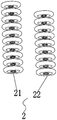
- Fig. 6 is a schematic diagram of the structure of a roller according to an embodiment of the present invention.
- Fig. 7 is an enlarged view of the roller groove of the circled part in Fig. 3 of the embodiment of the present invention.
- FIG. 8 is a schematic diagram of the structure of the first set of rollers and the second set of rollers according to the embodiment of the present invention.
- Fig. 9 is a schematic structural diagram of a fixed shaft according to an embodiment of the present invention.
- Fig. 10 is a structural diagram of a roller and a fixing unit according to an embodiment of the present invention.
- a half nut assembly includes a half nut 1, a roller 2, and a fixing unit.
- the roller 2 is mounted on the half nut 1 through the fixing unit.
- the inner surface of the half nut 1 is provided with a rolling groove 3, and the roller 2 rotates along the rolling groove 3.
- the half nut 1 is C-shaped, and a screw hole 6 is provided on the upper part of the half nut 1 and located at the central axis for fixing the transmission mechanism.
- the design is novel and the structure is simple.
- the edge of the roller 2 is provided with a protruding arc, and the arc design can better reduce the loss between the nut and the screw.
- the number of rollers 2 and rolling grooves 3 are the same.
- the rolling grooves 3 include a first set of notches 31 and a second set of notches 32, and a first set of notches 31 and a second set of grooves.
- the ports 32 are respectively located at both ends of the C-shaped half nut 1.
- the roller 2 includes a first group of rollers 21 and a second group of rollers 22, the first group of rollers 21 rotate along the first group of slots 31, and the second group of rollers 22 rotate along the second group of slots 32.
- both the first group of notches 31 and the second group of notches 32 include at least two roller grooves 4, and the number of roller grooves 4 of the first group of notches 31 is greater than the number of roller grooves 4 of the second group of notches 32.
- the roller grooves 4 of the second group of notches 32 are located between the roller grooves 4 of the adjacent first group of notches 31.
- the first set of notches 31 and the second set of notches 32 are designed to be mutually staggered, which can accelerate the rolling between the screw and the nut in all directions, and improve the production efficiency.
- the fixed unit includes a fixed shaft 5 and a bearing sleeved on the fixed shaft 5.
- the fixed shaft 5 penetrates the upper and lower surfaces of the half nut 1 longitudinally and passes through the center of the roller 2.
- the number of fixed shafts 5 is two, which are respectively located at both ends of the C-shaped half nut 1, and each fixed shaft 5 passes through the center of the first set of rollers 21 and the second set of rollers 22, See Figure 10.
- the roller 2 is fixed on the half nut 1 by a fixed shaft 5, and the fixed shaft 5 is fixed by a bearing, which increases the stability of the half nut 1 assembly.
Landscapes
- Engineering & Computer Science (AREA)
- General Engineering & Computer Science (AREA)
- Mechanical Engineering (AREA)
- Transmission Devices (AREA)
Abstract
Description
本发明涉及机械设计技术领域,特别是涉及一种半螺母组件。The invention relates to the technical field of mechanical design, in particular to a half-nut assembly.
为了实现物体的准确搬运、传输,电气设备普遍利用螺杆螺母组件,通过电机控制螺杆的转动,将电机的旋转动作转换为螺母的直线运动,通过将载物台连接至螺母,从而实现电机准确控制载物台的平移、升降等直线位移。In order to realize the accurate handling and transmission of objects, electrical equipment generally uses screw and nut components. The rotation of the screw is controlled by a motor, and the rotation of the motor is converted into the linear movement of the nut. By connecting the stage to the nut, accurate control of the motor is realized. Linear displacement such as translation and lifting of the stage.
但是,目前工厂中的螺杆和螺母无法自由分离,需要将螺母从轴向切分为两半,进行半螺母传动。而且,离合式螺杆机构中的螺杆与铜制螺母为直接接触摩擦,磨损大、寿命短,需要定期更换螺母,严重影响生产效率。However, the screw and nut in the current factory cannot be separated freely, and the nut needs to be cut into two halves from the axial direction for half-nut transmission. Moreover, the screw and the copper nut in the clutch type screw mechanism are in direct contact and friction, which is large in wear and short in life. The nut needs to be replaced regularly, which seriously affects the production efficiency.
因此,设计一种可以提高生产效率的半螺母组件是具有重要意义的。Therefore, it is of great significance to design a half-nut assembly that can improve production efficiency.
发明内容Summary of the invention
针对现有技术中存在的技术问题,本发明的目的是:提供一种可有效防磨损的半螺母组件,继而能够提高生产效率。In view of the technical problems existing in the prior art, the purpose of the present invention is to provide a half-nut assembly that can effectively prevent wear, thereby improving production efficiency.
为了实现上述目的,本发明提供的技术方案如下:一种半螺母组件,包括半螺母、滚轮、固定单元,所述滚轮通过所述固定单元安装至所述半螺母上;所述半螺母的内表面设有滚槽,所述滚轮沿所述滚槽转动。In order to achieve the above objective, the technical solution provided by the present invention is as follows: a half nut assembly, including a half nut, a roller, and a fixing unit. The roller is mounted on the half nut through the fixing unit; the inner part of the half nut The surface is provided with a rolling groove, and the roller rotates along the rolling groove.
优选地,所述滚轮和所述滚槽的数量一致;所述滚槽包括第一组槽口和第二组槽口,所述第一组槽口和所述第二组槽口分别位于所述半螺母的两端;所述滚轮包括第一组滚轮和第二组滚轮,所述第一组滚轮沿 所述第一组槽口转动,所述第二组滚轮沿所述第二组槽口转动。Preferably, the numbers of the rollers and the rolling grooves are the same; the rolling grooves include a first set of notches and a second set of notches, and the first set of notches and the second set of notches are respectively located at the first set of notches and the second set of notches. The two ends of the half nut; the roller includes a first set of rollers and a second set of rollers, the first set of rollers rotate along the first set of slots, the second set of rollers along the second set of slots Mouth rotation.
优选地,所述第一组槽口和所述第二组槽口均包括至少两个滚轮槽;所述第一组槽口的滚轮槽数量大于所述第二组槽口的滚轮槽数量。Preferably, both the first set of notches and the second set of notches include at least two roller grooves; the number of roller grooves of the first set of notches is greater than the number of roller grooves of the second set of notches.
优选地,在同一水平线上,所述第二组槽口的滚轮槽位于相邻所述第一组槽口的滚轮槽之间。Preferably, on the same horizontal line, the roller grooves of the second set of notches are located between the roller grooves of the adjacent first set of notches.
优选地,所述固定单元包括固定轴和套设于所述固定轴上的轴承,所述固定轴纵向穿射所述半螺母的上下表面,且穿过所述滚轮的中心处。Preferably, the fixing unit includes a fixing shaft and a bearing sleeved on the fixing shaft, and the fixing shaft penetrates the upper and lower surfaces of the half nut longitudinally and passes through the center of the roller.
优选地,所述固定轴的数量为两个,且每个所述固定轴分别穿过所述第一组滚轮和所述第二组滚轮的中心处。Preferably, the number of the fixed shafts is two, and each of the fixed shafts respectively passes through the center of the first set of rollers and the second set of rollers.
优选地,所述半螺母上设有螺孔,用于固定传动机构。Preferably, a screw hole is provided on the half nut for fixing the transmission mechanism.
优选地,所述螺孔位于所述半螺母的上方。Preferably, the screw hole is located above the half nut.
优选地,所述滚轮的边缘设有突出圆弧。Preferably, the edge of the roller is provided with a protruding arc.
优选地,所述半螺母呈C型。Preferably, the half nut is C-shaped.
与现有技术相比,本发明的有益效果在于:本发明所述的半螺母组件,包括半螺母、滚轮、固定单元,滚轮通过固定单元安装至半螺母上,半螺母的内表面设有滚槽,滚轮沿滚槽转动;通过设置在半螺母内表面的滚槽与滚轮的相互配合,实现将滑动摩擦变为滚动摩擦,降低螺母的损耗,降低更换频率,提高生产效率。Compared with the prior art, the beneficial effect of the present invention is that the half nut assembly of the present invention includes a half nut, a roller, and a fixing unit. The roller is mounted on the half nut through the fixing unit, and the inner surface of the half nut is provided with a roller. The groove and the roller rotate along the groove; through the mutual cooperation of the groove and the roller provided on the inner surface of the half nut, sliding friction is changed into rolling friction, which reduces the loss of the nut, reduces the frequency of replacement, and improves production efficiency.
图1是本发明实施例半螺母组件的主视图;Figure 1 is a front view of a half-nut assembly according to an embodiment of the present invention;
图2是本发明实施例半螺母组件的俯视图;Figure 2 is a top view of a half-nut assembly according to an embodiment of the present invention;
图3是本发明实施例半螺母组件的爆炸图;Figure 3 is an exploded view of the half-nut assembly of the embodiment of the present invention;
图4是本发明实施例半螺母的主视图;Figure 4 is a front view of the half nut of the embodiment of the present invention;
图5是本发明实施例半螺母的侧视图;Figure 5 is a side view of the half nut of the embodiment of the present invention;
图6是本发明实施例滚轮的结构示意图;Fig. 6 is a schematic diagram of the structure of a roller according to an embodiment of the present invention;
图7是本发明实施例图3中圈出部位滚轮槽的放大图;Fig. 7 is an enlarged view of the roller groove of the circled part in Fig. 3 of the embodiment of the present invention;
图8是本发明实施例第一组滚轮和第二组滚轮的结构示意图;8 is a schematic diagram of the structure of the first set of rollers and the second set of rollers according to the embodiment of the present invention;
图9是本发明实施例固定轴的结构示意图;Fig. 9 is a schematic structural diagram of a fixed shaft according to an embodiment of the present invention;
图10是本发明实施例滚轮和固定单元的结构示意图。Fig. 10 is a structural diagram of a roller and a fixing unit according to an embodiment of the present invention.
为了使本领域的技术人员更好地理解本发明中的技术方案,下面将结合本发明实施例中的附图,对本发明实施例中的技术方案进行清楚、完整地描述,显然,所描述的实施例仅仅是本发明一部分实施例,而不是全部的实施例。基于本发明中的实施例,本领域普通技术人员在没有做出创造性劳动前提下所获得的所有其他实施例,都应当属于本发明保护的范围。In order to enable those skilled in the art to better understand the technical solutions of the present invention, the following will clearly and completely describe the technical solutions in the embodiments of the present invention with reference to the accompanying drawings in the embodiments of the present invention. Obviously, the described The embodiments are only a part of the embodiments of the present invention, rather than all the embodiments. Based on the embodiments of the present invention, all other embodiments obtained by those of ordinary skill in the art without creative work shall fall within the protection scope of the present invention.
如图1至图3所示,本发明优选实施例的一种半螺母组件,包括半螺母1、滚轮2、固定单元,滚轮2通过固定单元安装至半螺母1上。半螺母1的内表面设有滚槽3,滚轮2沿滚槽3转动。通过设置在半螺母1内表面的滚槽3与滚轮2的相互配合,实现将滑动摩擦变为滚动摩擦,降低螺母的损耗,提高生产效率。As shown in Figs. 1 to 3, a half nut assembly according to a preferred embodiment of the present invention includes a
如图4和图5所示,半螺母1呈C型,半螺母1的上方且位于中心轴处设有螺孔6,用于固定传动机构,设计新颖、结构简单。As shown in Figures 4 and 5, the
如图6至图8所示,滚轮2的边缘设有突出圆弧,采用圆弧设计可以更好的降低螺母与螺杆之间的损耗。在本发明所述的半螺母组件中,滚轮2和滚槽3的数量一致,滚槽3包括第一组槽口31和第二组槽口32,第一组槽口31和第二组槽口32分别位于C型半螺母1的两端。滚轮2包括第一组滚轮21和第二组滚轮22,第一组滚轮21沿第一组槽口31转动,第二组滚轮22沿第二组槽口32转动。As shown in Figures 6 to 8, the edge of the
具体的,第一组槽口31和第二组槽口32均包括至少两个滚轮槽4,而第一组槽口31的滚轮槽4数量大于第二组槽口32的滚轮槽4数量。 当第一组槽口31和第二组槽口32在同一水平线上,第二组槽口32的滚轮槽4位于相邻第一组槽口31的滚轮槽4之间。将第一组槽口31和第二组槽口32设计为相互错开的状态,能够全方位加速螺杆与螺母之间的滚动,提高生产效率。Specifically, both the first group of
如图9所示,固定单元包括固定轴5和套设于固定轴5上的轴承,固定轴5纵向穿射半螺母1的上下表面,且穿过滚轮2的中心处。在本实施例中,固定轴5的数量为两个,分别位于C型半螺母1的两端,且每个固定轴5分别穿过第一组滚轮21和第二组滚轮22的中心处,参见图10。滚轮2通过固定轴5固定在半螺母1上,固定轴5通过轴承进行固定,增加半螺母1组件的稳定性。As shown in FIG. 9, the fixed unit includes a
采用本发明所述的半螺母组件,即使手动升降设备,螺杆与螺母之间的摩擦由滑动摩擦改为滚动摩擦,使得螺杆与螺母的磨损变小,延长其寿命,无需频繁更换螺母,大幅度提高了生产效率。With the half-nut assembly of the present invention, even with manual lifting equipment, the friction between the screw and the nut is changed from sliding friction to rolling friction, so that the wear of the screw and the nut is reduced, and its life is prolonged. There is no need to replace the nut frequently. Improve production efficiency.
应当理解,虽然本说明书按照实施例加以描述,但并非每个实施例仅包含一个独立的技术方案,说明书的这种叙述方式仅仅是为清楚起见,本领域技术人员应当将说明书作为一个整体,各实施例中的技术方案也可以经适当组合,形成本领域技术人员可以理解的其他实施例。It should be understood that although this specification is described in accordance with the embodiments, not each embodiment only contains an independent technical solution. This narration in the specification is only for clarity, and those skilled in the art should regard the specification as a whole. The technical solutions in the embodiments can also be appropriately combined to form other embodiments that can be understood by those skilled in the art.
上文所列出的一系列的详细说明仅仅是针对本发明的可行性实施例的具体说明,并非用以限制本发明的保护范围,凡未脱离本发明技艺精神所作的等效实施例或变更均应包含在本发明的保护范围之内。The series of detailed descriptions listed above are only specific descriptions of feasible embodiments of the present invention, and are not intended to limit the scope of protection of the present invention. Any equivalent embodiments or changes made without departing from the technical spirit of the present invention All should be included in the protection scope of the present invention.
Claims (10)
Applications Claiming Priority (2)
| Application Number | Priority Date | Filing Date | Title |
|---|---|---|---|
| CN201911346250.X | 2019-12-24 | ||
| CN201911346250.XA CN111120608B (en) | 2019-12-24 | 2019-12-24 | Half nut assembly |
Publications (1)
| Publication Number | Publication Date |
|---|---|
| WO2021129099A1 true WO2021129099A1 (en) | 2021-07-01 |
Family
ID=70501952
Family Applications (1)
| Application Number | Title | Priority Date | Filing Date |
|---|---|---|---|
| PCT/CN2020/123040 Ceased WO2021129099A1 (en) | 2019-12-24 | 2020-10-23 | Half-nut assembly |
Country Status (2)
| Country | Link |
|---|---|
| CN (1) | CN111120608B (en) |
| WO (1) | WO2021129099A1 (en) |
Families Citing this family (1)
| Publication number | Priority date | Publication date | Assignee | Title |
|---|---|---|---|---|
| CN111120608B (en) * | 2019-12-24 | 2022-04-22 | 颀中科技(苏州)有限公司 | Half nut assembly |
Citations (11)
| Publication number | Priority date | Publication date | Assignee | Title |
|---|---|---|---|---|
| CN2130962Y (en) * | 1992-06-12 | 1993-04-28 | 浙江省衢州汽车运输总公司 | Roller screw pair |
| JPH07251230A (en) * | 1994-03-16 | 1995-10-03 | Honda Motor Co Ltd | Ball screw shaft manufacturing method and manufacturing apparatus |
| CN200985997Y (en) * | 2006-12-25 | 2007-12-05 | 中国船舶重工集团公司第七一三研究所 | Semi-nut chain transmission mechanism capable of self locking |
| CN102562986A (en) * | 2012-03-22 | 2012-07-11 | 上海久能机电制造有限公司 | Planetary roller screw |
| DE202012010203U1 (en) * | 2012-07-17 | 2012-12-14 | Hermann Riedmann | Screw drive with integrated bearing units in the nut |
| CN103629319A (en) * | 2013-12-11 | 2014-03-12 | 洪荣华 | Pin roller bearing nut and screw rod pair |
| CN204267628U (en) * | 2014-11-26 | 2015-04-15 | 西安热工研究院有限公司 | A kind of two screw thread half-nut rail telescopic mechanism |
| CN106321762A (en) * | 2016-11-08 | 2017-01-11 | 山东华准机械有限公司 | High-speed roller screw pair |
| CN108561522A (en) * | 2018-04-23 | 2018-09-21 | 徐茹茹 | Radial roller lead screw |
| CN208057861U (en) * | 2018-03-23 | 2018-11-06 | 扬州众孚传动科技有限公司 | A kind of dead axle planetary screw lead |
| CN111120608A (en) * | 2019-12-24 | 2020-05-08 | 颀中科技(苏州)有限公司 | A half nut assembly |
Family Cites Families (5)
| Publication number | Priority date | Publication date | Assignee | Title |
|---|---|---|---|---|
| CH621392A5 (en) * | 1978-02-23 | 1981-01-30 | Fernand Moser | |
| SU1446394A1 (en) * | 1987-07-01 | 1988-12-23 | Институт Технической Кибернетики Ан Бсср | Screw mechanism |
| DE19542453C2 (en) * | 1995-11-14 | 1998-05-20 | Karl Hehl | Device for converting a rotary movement into an axial movement |
| CN201042546Y (en) * | 2007-02-08 | 2008-04-02 | 林美娟 | Propulsion mechanism of microinjection pump |
| CN105546068A (en) * | 2014-10-28 | 2016-05-04 | 盐城工业职业技术学院 | Compensating mechanism for screw transmission clearances |
-
2019
- 2019-12-24 CN CN201911346250.XA patent/CN111120608B/en active Active
-
2020
- 2020-10-23 WO PCT/CN2020/123040 patent/WO2021129099A1/en not_active Ceased
Patent Citations (11)
| Publication number | Priority date | Publication date | Assignee | Title |
|---|---|---|---|---|
| CN2130962Y (en) * | 1992-06-12 | 1993-04-28 | 浙江省衢州汽车运输总公司 | Roller screw pair |
| JPH07251230A (en) * | 1994-03-16 | 1995-10-03 | Honda Motor Co Ltd | Ball screw shaft manufacturing method and manufacturing apparatus |
| CN200985997Y (en) * | 2006-12-25 | 2007-12-05 | 中国船舶重工集团公司第七一三研究所 | Semi-nut chain transmission mechanism capable of self locking |
| CN102562986A (en) * | 2012-03-22 | 2012-07-11 | 上海久能机电制造有限公司 | Planetary roller screw |
| DE202012010203U1 (en) * | 2012-07-17 | 2012-12-14 | Hermann Riedmann | Screw drive with integrated bearing units in the nut |
| CN103629319A (en) * | 2013-12-11 | 2014-03-12 | 洪荣华 | Pin roller bearing nut and screw rod pair |
| CN204267628U (en) * | 2014-11-26 | 2015-04-15 | 西安热工研究院有限公司 | A kind of two screw thread half-nut rail telescopic mechanism |
| CN106321762A (en) * | 2016-11-08 | 2017-01-11 | 山东华准机械有限公司 | High-speed roller screw pair |
| CN208057861U (en) * | 2018-03-23 | 2018-11-06 | 扬州众孚传动科技有限公司 | A kind of dead axle planetary screw lead |
| CN108561522A (en) * | 2018-04-23 | 2018-09-21 | 徐茹茹 | Radial roller lead screw |
| CN111120608A (en) * | 2019-12-24 | 2020-05-08 | 颀中科技(苏州)有限公司 | A half nut assembly |
Also Published As
| Publication number | Publication date |
|---|---|
| CN111120608B (en) | 2022-04-22 |
| CN111120608A (en) | 2020-05-08 |
Similar Documents
| Publication | Publication Date | Title |
|---|---|---|
| US2525326A (en) | Antifriction transmission | |
| WO2012120670A1 (en) | Linear actuator | |
| CN104373541A (en) | Idler wheel type guide structure for ball screw pair | |
| WO2020062647A1 (en) | Oldham ring, an oldham coupling, and a harmonic reducer | |
| US7611128B2 (en) | Lifter | |
| CN111120608B (en) | Half nut assembly | |
| CN204572990U (en) | A kind of ball screw precision auger transmission device | |
| US20150139759A1 (en) | Rotation mechanism | |
| CN206592512U (en) | A kind of driven disk cam mechanism of plane motion roller | |
| CN103697130B (en) | Nut Rotary Linear Actuation Elements | |
| CN202833638U (en) | Novel subdivision aligning roller bearing | |
| WO2017024646A1 (en) | Bearing structure of main drive gearbox | |
| CN203158975U (en) | Rope sheave for elevator | |
| CN218509962U (en) | Double-row cylindrical roller bearing capable of bearing composite load | |
| CN217570189U (en) | Bearing seat convenient to maintain for rolling mill | |
| CN206738532U (en) | A kind of gear assembly applied to reductor | |
| CN208782708U (en) | A non-contact multistage magnetic coupling | |
| CN210623393U (en) | ATC ball groove linear rolling mechanism | |
| CN209648127U (en) | A kind of left-right rotary screw rod slide unit | |
| CN205029540U (en) | Super separation and reunion permanent magnetism speed regulator | |
| CN221940800U (en) | A new color-changing guide rail for embroidery machines | |
| CN107504145B (en) | A reducer with eccentric compensation follow-up mechanism | |
| CN114165527A (en) | Sliding key mechanism with ultralow friction force | |
| CN115383798A (en) | Electric scissors with non-slip teeth | |
| CN112065943A (en) | Linear motion speed synthesis mechanism |
Legal Events
| Date | Code | Title | Description |
|---|---|---|---|
| 121 | Ep: the epo has been informed by wipo that ep was designated in this application |
Ref document number: 20907129 Country of ref document: EP Kind code of ref document: A1 |
|
| NENP | Non-entry into the national phase |
Ref country code: DE |
|
| 122 | Ep: pct application non-entry in european phase |
Ref document number: 20907129 Country of ref document: EP Kind code of ref document: A1 |