WO2021127248A1 - Transportable rack for pressure safety/relief valves - Google Patents
Transportable rack for pressure safety/relief valves Download PDFInfo
- Publication number
- WO2021127248A1 WO2021127248A1 PCT/US2020/065715 US2020065715W WO2021127248A1 WO 2021127248 A1 WO2021127248 A1 WO 2021127248A1 US 2020065715 W US2020065715 W US 2020065715W WO 2021127248 A1 WO2021127248 A1 WO 2021127248A1
- Authority
- WO
- WIPO (PCT)
- Prior art keywords
- holes
- top plate
- particular size
- pressure rating
- circle
- Prior art date
- Legal status (The legal status is an assumption and is not a legal conclusion. Google has not performed a legal analysis and makes no representation as to the accuracy of the status listed.)
- Ceased
Links
Classifications
-
- F—MECHANICAL ENGINEERING; LIGHTING; HEATING; WEAPONS; BLASTING
- F16—ENGINEERING ELEMENTS AND UNITS; GENERAL MEASURES FOR PRODUCING AND MAINTAINING EFFECTIVE FUNCTIONING OF MACHINES OR INSTALLATIONS; THERMAL INSULATION IN GENERAL
- F16M—FRAMES, CASINGS OR BEDS OF ENGINES, MACHINES OR APPARATUS, NOT SPECIFIC TO ENGINES, MACHINES OR APPARATUS PROVIDED FOR ELSEWHERE; STANDS; SUPPORTS
- F16M11/00—Stands or trestles as supports for apparatus or articles placed thereon ; Stands for scientific apparatus such as gravitational force meters
- F16M11/20—Undercarriages with or without wheels
- F16M11/2007—Undercarriages with or without wheels comprising means allowing pivoting adjustment
-
- B—PERFORMING OPERATIONS; TRANSPORTING
- B65—CONVEYING; PACKING; STORING; HANDLING THIN OR FILAMENTARY MATERIAL
- B65D—CONTAINERS FOR STORAGE OR TRANSPORT OF ARTICLES OR MATERIALS, e.g. BAGS, BARRELS, BOTTLES, BOXES, CANS, CARTONS, CRATES, DRUMS, JARS, TANKS, HOPPERS, FORWARDING CONTAINERS; ACCESSORIES, CLOSURES, OR FITTINGS THEREFOR; PACKAGING ELEMENTS; PACKAGES
- B65D19/00—Pallets or like platforms, with or without side walls, for supporting loads to be lifted or lowered
-
- B—PERFORMING OPERATIONS; TRANSPORTING
- B65—CONVEYING; PACKING; STORING; HANDLING THIN OR FILAMENTARY MATERIAL
- B65D—CONTAINERS FOR STORAGE OR TRANSPORT OF ARTICLES OR MATERIALS, e.g. BAGS, BARRELS, BOTTLES, BOXES, CANS, CARTONS, CRATES, DRUMS, JARS, TANKS, HOPPERS, FORWARDING CONTAINERS; ACCESSORIES, CLOSURES, OR FITTINGS THEREFOR; PACKAGING ELEMENTS; PACKAGES
- B65D19/00—Pallets or like platforms, with or without side walls, for supporting loads to be lifted or lowered
- B65D19/38—Details or accessories
- B65D19/44—Elements or devices for locating articles on platforms
-
- B—PERFORMING OPERATIONS; TRANSPORTING
- B65—CONVEYING; PACKING; STORING; HANDLING THIN OR FILAMENTARY MATERIAL
- B65D—CONTAINERS FOR STORAGE OR TRANSPORT OF ARTICLES OR MATERIALS, e.g. BAGS, BARRELS, BOTTLES, BOXES, CANS, CARTONS, CRATES, DRUMS, JARS, TANKS, HOPPERS, FORWARDING CONTAINERS; ACCESSORIES, CLOSURES, OR FITTINGS THEREFOR; PACKAGING ELEMENTS; PACKAGES
- B65D85/00—Containers, packaging elements or packages, specially adapted for particular articles or materials
- B65D85/68—Containers, packaging elements or packages, specially adapted for particular articles or materials for machines, engines or vehicles in assembled or dismantled form
-
- F—MECHANICAL ENGINEERING; LIGHTING; HEATING; WEAPONS; BLASTING
- F16—ENGINEERING ELEMENTS AND UNITS; GENERAL MEASURES FOR PRODUCING AND MAINTAINING EFFECTIVE FUNCTIONING OF MACHINES OR INSTALLATIONS; THERMAL INSULATION IN GENERAL
- F16B—DEVICES FOR FASTENING OR SECURING CONSTRUCTIONAL ELEMENTS OR MACHINE PARTS TOGETHER, e.g. NAILS, BOLTS, CIRCLIPS, CLAMPS, CLIPS OR WEDGES; JOINTS OR JOINTING
- F16B5/00—Joining sheets or plates, e.g. panels, to one another or to strips or bars parallel to them
- F16B5/02—Joining sheets or plates, e.g. panels, to one another or to strips or bars parallel to them by means of fastening members using screw-thread
- F16B5/0283—Joining sheets or plates, e.g. panels, to one another or to strips or bars parallel to them by means of fastening members using screw-thread with an externally threaded sleeve around the neck or the head of the screw-threaded element for adjustably fastening a plate or frame or the like to a fixed element
-
- F—MECHANICAL ENGINEERING; LIGHTING; HEATING; WEAPONS; BLASTING
- F16—ENGINEERING ELEMENTS AND UNITS; GENERAL MEASURES FOR PRODUCING AND MAINTAINING EFFECTIVE FUNCTIONING OF MACHINES OR INSTALLATIONS; THERMAL INSULATION IN GENERAL
- F16K—VALVES; TAPS; COCKS; ACTUATING-FLOATS; DEVICES FOR VENTING OR AERATING
- F16K11/00—Multiple-way valves, e.g. mixing valves; Pipe fittings incorporating such valves
- F16K11/02—Multiple-way valves, e.g. mixing valves; Pipe fittings incorporating such valves with all movable sealing faces moving as one unit
- F16K11/06—Multiple-way valves, e.g. mixing valves; Pipe fittings incorporating such valves with all movable sealing faces moving as one unit comprising only sliding valves, i.e. sliding closure elements
- F16K11/065—Multiple-way valves, e.g. mixing valves; Pipe fittings incorporating such valves with all movable sealing faces moving as one unit comprising only sliding valves, i.e. sliding closure elements with linearly sliding closure members
-
- F—MECHANICAL ENGINEERING; LIGHTING; HEATING; WEAPONS; BLASTING
- F16—ENGINEERING ELEMENTS AND UNITS; GENERAL MEASURES FOR PRODUCING AND MAINTAINING EFFECTIVE FUNCTIONING OF MACHINES OR INSTALLATIONS; THERMAL INSULATION IN GENERAL
- F16K—VALVES; TAPS; COCKS; ACTUATING-FLOATS; DEVICES FOR VENTING OR AERATING
- F16K17/00—Safety valves; Equalising valves, e.g. pressure relief valves
-
- B—PERFORMING OPERATIONS; TRANSPORTING
- B65—CONVEYING; PACKING; STORING; HANDLING THIN OR FILAMENTARY MATERIAL
- B65D—CONTAINERS FOR STORAGE OR TRANSPORT OF ARTICLES OR MATERIALS, e.g. BAGS, BARRELS, BOTTLES, BOXES, CANS, CARTONS, CRATES, DRUMS, JARS, TANKS, HOPPERS, FORWARDING CONTAINERS; ACCESSORIES, CLOSURES, OR FITTINGS THEREFOR; PACKAGING ELEMENTS; PACKAGES
- B65D2519/00—Pallets or like platforms, with or without side walls, for supporting loads to be lifted or lowered
- B65D2519/00004—Details relating to pallets
- B65D2519/00009—Materials
- B65D2519/00014—Materials for the load supporting surface
- B65D2519/00024—Metal
-
- B—PERFORMING OPERATIONS; TRANSPORTING
- B65—CONVEYING; PACKING; STORING; HANDLING THIN OR FILAMENTARY MATERIAL
- B65D—CONTAINERS FOR STORAGE OR TRANSPORT OF ARTICLES OR MATERIALS, e.g. BAGS, BARRELS, BOTTLES, BOXES, CANS, CARTONS, CRATES, DRUMS, JARS, TANKS, HOPPERS, FORWARDING CONTAINERS; ACCESSORIES, CLOSURES, OR FITTINGS THEREFOR; PACKAGING ELEMENTS; PACKAGES
- B65D2519/00—Pallets or like platforms, with or without side walls, for supporting loads to be lifted or lowered
- B65D2519/00004—Details relating to pallets
- B65D2519/00009—Materials
- B65D2519/00049—Materials for the base surface
- B65D2519/00059—Metal
-
- B—PERFORMING OPERATIONS; TRANSPORTING
- B65—CONVEYING; PACKING; STORING; HANDLING THIN OR FILAMENTARY MATERIAL
- B65D—CONTAINERS FOR STORAGE OR TRANSPORT OF ARTICLES OR MATERIALS, e.g. BAGS, BARRELS, BOTTLES, BOXES, CANS, CARTONS, CRATES, DRUMS, JARS, TANKS, HOPPERS, FORWARDING CONTAINERS; ACCESSORIES, CLOSURES, OR FITTINGS THEREFOR; PACKAGING ELEMENTS; PACKAGES
- B65D2519/00—Pallets or like platforms, with or without side walls, for supporting loads to be lifted or lowered
- B65D2519/00004—Details relating to pallets
- B65D2519/00009—Materials
- B65D2519/00119—Materials for the construction of the reinforcements
- B65D2519/00129—Metal
-
- B—PERFORMING OPERATIONS; TRANSPORTING
- B65—CONVEYING; PACKING; STORING; HANDLING THIN OR FILAMENTARY MATERIAL
- B65D—CONTAINERS FOR STORAGE OR TRANSPORT OF ARTICLES OR MATERIALS, e.g. BAGS, BARRELS, BOTTLES, BOXES, CANS, CARTONS, CRATES, DRUMS, JARS, TANKS, HOPPERS, FORWARDING CONTAINERS; ACCESSORIES, CLOSURES, OR FITTINGS THEREFOR; PACKAGING ELEMENTS; PACKAGES
- B65D2519/00—Pallets or like platforms, with or without side walls, for supporting loads to be lifted or lowered
- B65D2519/00004—Details relating to pallets
- B65D2519/00258—Overall construction
- B65D2519/00263—Overall construction of the pallet
- B65D2519/00273—Overall construction of the pallet made of more than one piece
-
- B—PERFORMING OPERATIONS; TRANSPORTING
- B65—CONVEYING; PACKING; STORING; HANDLING THIN OR FILAMENTARY MATERIAL
- B65D—CONTAINERS FOR STORAGE OR TRANSPORT OF ARTICLES OR MATERIALS, e.g. BAGS, BARRELS, BOTTLES, BOXES, CANS, CARTONS, CRATES, DRUMS, JARS, TANKS, HOPPERS, FORWARDING CONTAINERS; ACCESSORIES, CLOSURES, OR FITTINGS THEREFOR; PACKAGING ELEMENTS; PACKAGES
- B65D2519/00—Pallets or like platforms, with or without side walls, for supporting loads to be lifted or lowered
- B65D2519/00004—Details relating to pallets
- B65D2519/00258—Overall construction
- B65D2519/00283—Overall construction of the load supporting surface
- B65D2519/00288—Overall construction of the load supporting surface made of one piece
-
- B—PERFORMING OPERATIONS; TRANSPORTING
- B65—CONVEYING; PACKING; STORING; HANDLING THIN OR FILAMENTARY MATERIAL
- B65D—CONTAINERS FOR STORAGE OR TRANSPORT OF ARTICLES OR MATERIALS, e.g. BAGS, BARRELS, BOTTLES, BOXES, CANS, CARTONS, CRATES, DRUMS, JARS, TANKS, HOPPERS, FORWARDING CONTAINERS; ACCESSORIES, CLOSURES, OR FITTINGS THEREFOR; PACKAGING ELEMENTS; PACKAGES
- B65D2519/00—Pallets or like platforms, with or without side walls, for supporting loads to be lifted or lowered
- B65D2519/00004—Details relating to pallets
- B65D2519/00258—Overall construction
- B65D2519/00283—Overall construction of the load supporting surface
- B65D2519/00308—Overall construction of the load supporting surface grid type, e.g. perforated plate
-
- B—PERFORMING OPERATIONS; TRANSPORTING
- B65—CONVEYING; PACKING; STORING; HANDLING THIN OR FILAMENTARY MATERIAL
- B65D—CONTAINERS FOR STORAGE OR TRANSPORT OF ARTICLES OR MATERIALS, e.g. BAGS, BARRELS, BOTTLES, BOXES, CANS, CARTONS, CRATES, DRUMS, JARS, TANKS, HOPPERS, FORWARDING CONTAINERS; ACCESSORIES, CLOSURES, OR FITTINGS THEREFOR; PACKAGING ELEMENTS; PACKAGES
- B65D2519/00—Pallets or like platforms, with or without side walls, for supporting loads to be lifted or lowered
- B65D2519/00004—Details relating to pallets
- B65D2519/00258—Overall construction
- B65D2519/00313—Overall construction of the base surface
- B65D2519/00323—Overall construction of the base surface made of more than one piece
-
- B—PERFORMING OPERATIONS; TRANSPORTING
- B65—CONVEYING; PACKING; STORING; HANDLING THIN OR FILAMENTARY MATERIAL
- B65D—CONTAINERS FOR STORAGE OR TRANSPORT OF ARTICLES OR MATERIALS, e.g. BAGS, BARRELS, BOTTLES, BOXES, CANS, CARTONS, CRATES, DRUMS, JARS, TANKS, HOPPERS, FORWARDING CONTAINERS; ACCESSORIES, CLOSURES, OR FITTINGS THEREFOR; PACKAGING ELEMENTS; PACKAGES
- B65D2519/00—Pallets or like platforms, with or without side walls, for supporting loads to be lifted or lowered
- B65D2519/00004—Details relating to pallets
- B65D2519/00258—Overall construction
- B65D2519/00313—Overall construction of the base surface
- B65D2519/00328—Overall construction of the base surface shape of the contact surface of the base
- B65D2519/00333—Overall construction of the base surface shape of the contact surface of the base contact surface having a stringer-like shape
-
- B—PERFORMING OPERATIONS; TRANSPORTING
- B65—CONVEYING; PACKING; STORING; HANDLING THIN OR FILAMENTARY MATERIAL
- B65D—CONTAINERS FOR STORAGE OR TRANSPORT OF ARTICLES OR MATERIALS, e.g. BAGS, BARRELS, BOTTLES, BOXES, CANS, CARTONS, CRATES, DRUMS, JARS, TANKS, HOPPERS, FORWARDING CONTAINERS; ACCESSORIES, CLOSURES, OR FITTINGS THEREFOR; PACKAGING ELEMENTS; PACKAGES
- B65D2519/00—Pallets or like platforms, with or without side walls, for supporting loads to be lifted or lowered
- B65D2519/00004—Details relating to pallets
- B65D2519/00258—Overall construction
- B65D2519/00398—Overall construction reinforcements
- B65D2519/00432—Non-integral, e.g. inserts
- B65D2519/00437—Non-integral, e.g. inserts on the load supporting surface
-
- B—PERFORMING OPERATIONS; TRANSPORTING
- B65—CONVEYING; PACKING; STORING; HANDLING THIN OR FILAMENTARY MATERIAL
- B65D—CONTAINERS FOR STORAGE OR TRANSPORT OF ARTICLES OR MATERIALS, e.g. BAGS, BARRELS, BOTTLES, BOXES, CANS, CARTONS, CRATES, DRUMS, JARS, TANKS, HOPPERS, FORWARDING CONTAINERS; ACCESSORIES, CLOSURES, OR FITTINGS THEREFOR; PACKAGING ELEMENTS; PACKAGES
- B65D2519/00—Pallets or like platforms, with or without side walls, for supporting loads to be lifted or lowered
- B65D2519/00004—Details relating to pallets
- B65D2519/00547—Connections
- B65D2519/00552—Structures connecting the constitutive elements of the pallet to each other, i.e. load supporting surface, base surface and/or separate spacer
- B65D2519/00557—Structures connecting the constitutive elements of the pallet to each other, i.e. load supporting surface, base surface and/or separate spacer without separate auxiliary elements
- B65D2519/00562—Structures connecting the constitutive elements of the pallet to each other, i.e. load supporting surface, base surface and/or separate spacer without separate auxiliary elements chemical connection, e.g. glued, welded, sealed
-
- B—PERFORMING OPERATIONS; TRANSPORTING
- B65—CONVEYING; PACKING; STORING; HANDLING THIN OR FILAMENTARY MATERIAL
- B65D—CONTAINERS FOR STORAGE OR TRANSPORT OF ARTICLES OR MATERIALS, e.g. BAGS, BARRELS, BOTTLES, BOXES, CANS, CARTONS, CRATES, DRUMS, JARS, TANKS, HOPPERS, FORWARDING CONTAINERS; ACCESSORIES, CLOSURES, OR FITTINGS THEREFOR; PACKAGING ELEMENTS; PACKAGES
- B65D2519/00—Pallets or like platforms, with or without side walls, for supporting loads to be lifted or lowered
- B65D2519/00004—Details relating to pallets
- B65D2519/00547—Connections
- B65D2519/00552—Structures connecting the constitutive elements of the pallet to each other, i.e. load supporting surface, base surface and/or separate spacer
- B65D2519/00572—Structures connecting the constitutive elements of the pallet to each other, i.e. load supporting surface, base surface and/or separate spacer with separate auxiliary element, e.g. screws, nails, bayonets
-
- B—PERFORMING OPERATIONS; TRANSPORTING
- B65—CONVEYING; PACKING; STORING; HANDLING THIN OR FILAMENTARY MATERIAL
- B65D—CONTAINERS FOR STORAGE OR TRANSPORT OF ARTICLES OR MATERIALS, e.g. BAGS, BARRELS, BOTTLES, BOXES, CANS, CARTONS, CRATES, DRUMS, JARS, TANKS, HOPPERS, FORWARDING CONTAINERS; ACCESSORIES, CLOSURES, OR FITTINGS THEREFOR; PACKAGING ELEMENTS; PACKAGES
- B65D2519/00—Pallets or like platforms, with or without side walls, for supporting loads to be lifted or lowered
- B65D2519/00004—Details relating to pallets
- B65D2519/00736—Details
- B65D2519/0081—Elements or devices for locating articles
- B65D2519/00815—Elements or devices for locating articles on the pallet
-
- B—PERFORMING OPERATIONS; TRANSPORTING
- B65—CONVEYING; PACKING; STORING; HANDLING THIN OR FILAMENTARY MATERIAL
- B65D—CONTAINERS FOR STORAGE OR TRANSPORT OF ARTICLES OR MATERIALS, e.g. BAGS, BARRELS, BOTTLES, BOXES, CANS, CARTONS, CRATES, DRUMS, JARS, TANKS, HOPPERS, FORWARDING CONTAINERS; ACCESSORIES, CLOSURES, OR FITTINGS THEREFOR; PACKAGING ELEMENTS; PACKAGES
- B65D2585/00—Containers, packaging elements or packages specially adapted for particular articles or materials
- B65D2585/68—Containers, packaging elements or packages specially adapted for particular articles or materials for machines, engines, or vehicles in assembled or dismantled form
- B65D2585/6802—Containers, packaging elements or packages specially adapted for particular articles or materials for machines, engines, or vehicles in assembled or dismantled form specific machines, engines or vehicles
- B65D2585/6875—Containers, packaging elements or packages specially adapted for particular articles or materials for machines, engines, or vehicles in assembled or dismantled form specific machines, engines or vehicles engines, motors, machines and vehicle parts
-
- F—MECHANICAL ENGINEERING; LIGHTING; HEATING; WEAPONS; BLASTING
- F16—ENGINEERING ELEMENTS AND UNITS; GENERAL MEASURES FOR PRODUCING AND MAINTAINING EFFECTIVE FUNCTIONING OF MACHINES OR INSTALLATIONS; THERMAL INSULATION IN GENERAL
- F16B—DEVICES FOR FASTENING OR SECURING CONSTRUCTIONAL ELEMENTS OR MACHINE PARTS TOGETHER, e.g. NAILS, BOLTS, CIRCLIPS, CLAMPS, CLIPS OR WEDGES; JOINTS OR JOINTING
- F16B2200/00—Constructional details of connections not covered for in other groups of this subclass
- F16B2200/50—Flanged connections
- F16B2200/503—Flanged connections the flange being separate from the elements to be connected
Definitions
- the present invention relates generally to the transportation and storage of flanged valves, and more particularly to the transportation and storage of flanged pressure relief valves and pressure safety valves.
- PS valves Pressure safety valves
- PR valves pressure relief valves
- PS valves pressure relief valves
- PR valves pressure relief valves
- PS/PR valves pressure relief valves
- PS/PR valves appear to be very rugged components, yet these devices are delicate and have to be handled with extra caution, including during storage and transportation, to ensure their functionality is maintained and their accuracy is not compromised.
- PS/PR valve manufacturers recommend keeping the valves upright when stored or transported. The PS/PR valves should not be transported laying on their sides as they are more likely to sustain damage in this position.
- Valves such as PS/PR valves
- PS/PR valves are typically one of the first things removed from a unit during maintenance, outages or shutdowns. Valve removal and transportation delays can result in significant additional costs to any project, especially if the valve functionality is impacted due to rough handling during removal or if the valve end flanges are damaged due to improper transportation.
- valves particularly PS/PR valves. It is further desirable that the PS/PR valves be secured to the rack in an upright position. It is also desirable that the rack is versatile and able to accommodate a plurality of PS/PR valves, including a plurality of sizes of valves, a plurality of same size valves of different pressure ratings, and a combination of PS/PR valves of different sizes and ratings.
- a preferred embodiment of the invention is a transportable valve rack that allows a standard and quick transportation for a plurality of valves, including pressure safety valves and/or pressure relief valves (PS/PR valves), while in an upright position.
- the valve rack is also capable of accommodating valves, including PS/PR valves, of different sizes and pressure ratings. Additionally, the valves are secured to the rack to provide further protection against damage.
- the valve rack is also versatile to accommodate, store and transfer multiple PS/PR valves of the same size and pressure rating, the same size and different pressure ratings, different sizes, and different sizes and different pressure ratings.
- FIG. 1 is a perspective view of a transportable valve rack according to a preferred embodiment of the invention showing some valves mounted on the rack in an upright position;
- FIG. 2 is atop view of an illustrative embodiment of the transportable valve rack.
- a transportable valve rack is shown in perspective in Fig. 1 supporting a plurality of pressure safety and pressure relief valves (PS/PR valves), generally referred to as V, in an upright position on a valve flange F.
- the transportable valve rack 20 preferably includes a top plate 22 mounted on a base assembly 24.
- the top plate 22 preferably has a smooth, planer upper surface 26.
- the top plate 22 may be rectangular and may have a size of approximately four feet by four feet. It is to be understood that other shapes and sizes may also be used.
- the top plate 22 is securely and fixedly attached to the base assembly 24, as for example, by welds or bolts.
- the base assembly 24 preferably includes at least a pair of support members 28 which maintain the top plate 22 off the floor and provide a space between the floor and top plate 22.
- each support member 28 is a beam, preferably including a vertical web 30 connected to upper and lower horizontal flanges 32.
- the support members 28 are parallel to one another and extend along two opposing sides of the rectangular top plate 22.
- At least a pair of support braces 34 span between the vertical webs 30 of the support members 28.
- the support braces 34 are at an upper portion of the vertical webs 30 and adjacent the upper flanges and preferably abutting a lower surface 38 of the top plate 22.
- the support braces 34 are preferably attached to the vertical webs 30, upper flanges 32 and the top plate 22 by welding.
- the support braces 34 provide the top plate 22 with structural strength to prevent flexure of the top plate 22 between the support members 28 when loaded with the PS/PR valves V.
- the base assembly 24 provides support for the top plate 22 while also allowing for the transportable valve rack 20 to be easily moved, raised and/or transported using a forklift or similar device.
- the top plate 22 includes a plurality of holes 36, preferably circular, extending through the top plate 22 from the upper surface 26 to the lower surface 38.
- the plurality of holes 36 are sized, positioned and arranged to correspond with various pre selected flange bolt circle diameters, numbers of bolts, and diameters of bolts. This will be explained in greater detail below.
- the PS/PR valves V shown in Fig. 1 are secured to the transportable valve rack 20 by aligning all or at least some of the flange bolt holes 40 with top plate holes 36 corresponding to the flange size and pressure rating.
- flange bolt holes 40 aligned with corresponding top plate holes 36
- threaded bolts 42 and nuts 44 may be used to secure the PS/PR valves V to the transportable valve rack 20 in their upright (vertical) position.
- the bolts 42 typically stud bolts, extend above and through the flange bolt hole 40, and through and below the top plate hole 36 and upper and lower nuts 44 are threaded onto the stud bolt 42. Once bolted to the transportable valve rack 20, the valve(s) V is ready to be transported.
- each valve V is held in place by at least four bolts (depending on the size) spaced around the circumference of the valve flange F.
- Placement of the face of the flange F on the smooth, planer upper surface 26 of the top plate 22 and securing the valve V to the valve rack 20 ensures protection of the valve flanges F, including the exposed valve flange as everything on the valve rack 20 is secured against movements such as shifting and rolling.
- the transportable valve rack 20 is made of steel, preferably carbon steel material, and coated to prevent corrosion.
- Flange dimensions are determined by pipe size and pressure class required for the application. Most of these dimensions have been standardized and published as ASME, API or other standardization organization specifications. ASME/ANSI B16.5 provides dimensions and tolerances for flanges in pipe sizes from 1 ⁇ 2” through 24” and in classes ranging 150 through 2500 (i.e., pressure ratings of 150 psi through 2500 psi).
- FIG. 2 An example of such a valve rack 20 is shown in Fig. 2.
- the top plate 22 is shown having twelve areas or groups of concentric circles.
- the concentric circles in each group have a common centerpoint.
- the groups are numbered 1 through 12 on Fig. 2.
- the pair of concentric circles in groups 1-4 are identical
- the pair of concentric circles in groups 5-8 are identical
- the seven concentric circles in groups 9-12 are identical.
- Each group of concentric circles is a location for securing a valve V to the valve rack 20.
- space permitting the valve rack 20 shown in Fig. 2 has twelve locations for securing valves V to the rack 20.
- each group includes seven concentric circles identified as A, B, C, D, E, F and G.
- Each of the seven concentric circles corresponds with at least one specific valve flange size and rating.
- each comer group of concentric circles is capable of having one valve V secured thereto selected from at least seven different valve flange sizes and ratings.
- Each of the four vertically-aligned groups 1, 2, 3 and 4 includes two concentric circles identified as H and I. Each of the two concentric circles corresponds with at least one specific valve flange size and rating. Thus, each of the four vertical groups of concentric circles is capable of having one valve V secured thereto selected from at least two different valve flange sizes and ratings.
- Each of the four horizontally-aligned groups 5, 6, 7 and 8, includes two concentric circles identified as J and K. Each of the two concentric circles corresponds with at least one specific valve flange size and rating. Thus, each of the four horizontal groups of concentric circles is capable of having one valve V secured thereto selected from at least two different valve flange sizes and ratings.
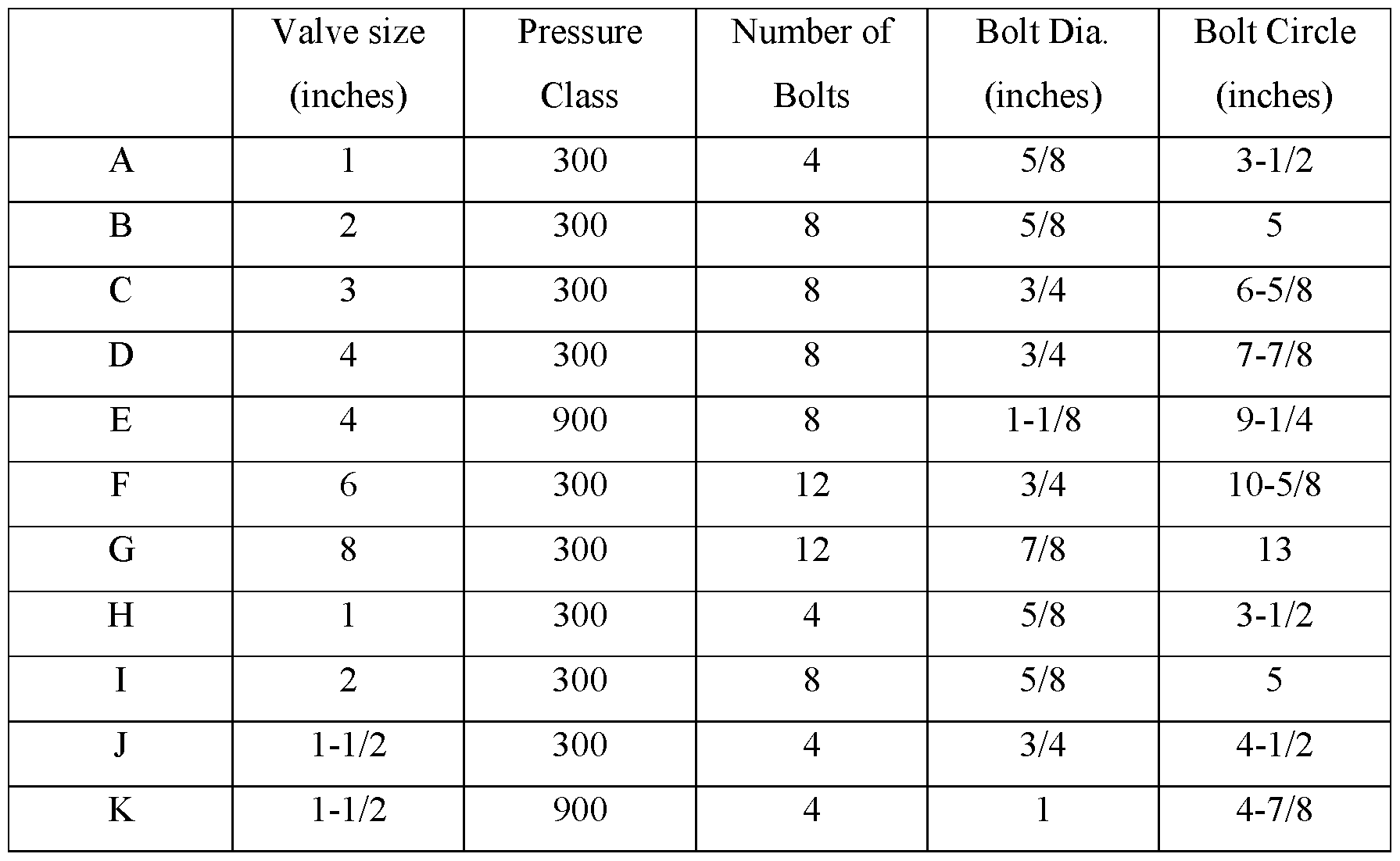
- valve size and pressure class, number of bolts, diameter of bolts and bolt circle diameter for A through K are listed below:
- the concentric circles A-K represent bolt circles.
- the four holes 36 are uniformly spaced and each hole 36 has a centerpoint on the circumference of a circle having a diameter of 4-1/2”.
- the holes 36 in the top plate 22 are approximately l/8 th inch larger in diameter than the bolt diameter.
- the holes 36 on concentric circle J would be 7/8” in diameter.
- Concentric circle J accommodates a 1-1/2” valve, class 300 having four flange bolts.
- the four holes 36 are uniformly spaced and have their centerpoints on a circle having a diameter of 4-7/8” and the holes 36 on concentric circle K are 1-1/8” in diameter.
- Concentric circle K accommodates a 1-1/2” valve, class 900 having four flange bolts.
- the holes 36 on concentric circle K are radially offset from the holes 36 on concentric circle J for purposes of spacing requirements and preventing the holes of the two concentric circles J and K from being too close to each other.
- concentric circles A-K represent bolt circles; however, not every concentric circle necessarily includes the number of holes corresponding to the specific valve flange F.
- concentric circle I has only four holes 36 even though it accommodates a 2” valve, class 300 having 8 flange bolts.
- the four holes 36 are preferably uniformly spaced and radially offset from the four holes on inner concentric circle H.
- the valve rack 20 includes at least four spaced holes for each flange size and rating it can accommodate.
- the top plate 22 has four holes spaced on the bolt circle diameter and spacing as shown on concentric circle G.
- the support braces 34 provide a lower surface 46 that provides an area suitable for a pair of forks of a fork lift or similar device to be positioned under for the purpose of lifting and transporting the valve rack 20. Additionally, it may be preferable that the distance between the lower surface 46 and the bottom of the support member 28 provides adequate space for a worker’s arm to extend through to install and tighten bolts 42 and nuts 44 when the valve rack 20 is resting on the floor.
- the spacing between the lower surface 46 of the support brace 34 and the lower surface 38 of the top plate 22 is greater than the required distance needed for the nut 44 and bolt 42 below the lower surface 38 of the top plate 22 so that the forks of the forklift will not come into contact with the bolts 42 and nuts 44.
- valve rack 20 can be designed specifically for the required PS/PR valves V that are present in the facility, including the quantities of each valve V in the facility.
- the rack illustration above can accommodate up to eight 1” valves, class 300 at one time, if needed, including space for valves V in groups 5, 6, 7 and 8.
- valve rack 20 shown in Fig. 2 can accommodate and store up to twelve valves V in an upright position. This number can be modified by adjusting the number of areas or groups.
- the transportable valve rack 20 includes one or more of the following features:
- valve V is secured to the rack 20 (valve V is mounted vertically on top of the top plate 22 and held in place by four bolts or so (depending on the size))
Landscapes
- Engineering & Computer Science (AREA)
- General Engineering & Computer Science (AREA)
- Mechanical Engineering (AREA)
- Valve Housings (AREA)
- Safety Valves (AREA)
Abstract
Description
Claims
Priority Applications (1)
| Application Number | Priority Date | Filing Date | Title |
|---|---|---|---|
| SA522432799A SA522432799B1 (en) | 2019-12-17 | 2022-05-30 | Transportable rack for pressure safety/relief valves |
Applications Claiming Priority (2)
| Application Number | Priority Date | Filing Date | Title |
|---|---|---|---|
| US16/717,899 US11619340B2 (en) | 2019-12-17 | 2019-12-17 | Transportable rack for pressure safety/relief valves |
| US16/717,899 | 2019-12-17 |
Publications (1)
| Publication Number | Publication Date |
|---|---|
| WO2021127248A1 true WO2021127248A1 (en) | 2021-06-24 |
Family
ID=74195108
Family Applications (1)
| Application Number | Title | Priority Date | Filing Date |
|---|---|---|---|
| PCT/US2020/065715 Ceased WO2021127248A1 (en) | 2019-12-17 | 2020-12-17 | Transportable rack for pressure safety/relief valves |
Country Status (3)
| Country | Link |
|---|---|
| US (1) | US11619340B2 (en) |
| SA (1) | SA522432799B1 (en) |
| WO (1) | WO2021127248A1 (en) |
Families Citing this family (5)
| Publication number | Priority date | Publication date | Assignee | Title |
|---|---|---|---|---|
| US11634259B2 (en) * | 2019-08-24 | 2023-04-25 | Logistics Advanced Research Center LLC | Reusable shipping platform for transporting multiple electrical circuit breakers |
| EP3919405B1 (en) * | 2020-06-04 | 2024-03-20 | ALWA GmbH & Co. KG Konstruktion & Formenbau | Device for holding objects |
| KR20220115249A (en) * | 2021-02-10 | 2022-08-17 | 현대자동차주식회사 | Pallet for transporting parts |
| US11878838B2 (en) * | 2021-03-16 | 2024-01-23 | Xcel Global Packaging Inc. | Pallet apparatus |
| CN113830395A (en) * | 2021-10-20 | 2021-12-24 | 安徽信息工程学院 | A parts transport device |
Citations (4)
| Publication number | Priority date | Publication date | Assignee | Title |
|---|---|---|---|---|
| DE102011111142A1 (en) * | 2011-08-20 | 2013-02-21 | Mikdat Akbas Oat | Electric motor mounting plate used during transportation of electric motors for use in vehicle, is ideally located for transport of electric motors irrespective of different flange diameter and spacing between mounting holes |
| KR20140014910A (en) * | 2012-07-27 | 2014-02-06 | 주식회사 참스 | Packing box for hub-bearing |
| US20180265249A1 (en) * | 2017-03-16 | 2018-09-20 | Caterpillar Inc. | Adjustable Pallet |
| DE202017004490U1 (en) * | 2017-08-29 | 2018-11-30 | Viebahn Systemtechnik Gmbh | Charge carrier for receiving cargo |
Family Cites Families (31)
| Publication number | Priority date | Publication date | Assignee | Title |
|---|---|---|---|---|
| US3636888A (en) * | 1970-05-04 | 1972-01-25 | Pack Rite Packaging & Crating | Pallet |
| US1864305A (en) | 1930-11-06 | 1932-06-21 | Int Harvester Co | Valve facing machine |
| US2312434A (en) | 1940-05-18 | 1943-03-02 | Herbert J Nathan | Carrier for poppet type engine valves |
| US2444326A (en) * | 1946-07-31 | 1948-06-29 | Autolift Accessory And Enginee | Material handling platform |
| US2548289A (en) | 1947-01-06 | 1951-04-10 | Thomas P Carraher | Valve rack |
| US2507588A (en) * | 1947-01-29 | 1950-05-16 | Pallet Devices Inc | Load supporting pallet |
| US3670878A (en) * | 1970-05-11 | 1972-06-20 | Martin W Seiler | Apparatus for shipment and storage of magnetic memory discs and the like |
| US3799333A (en) * | 1971-05-07 | 1974-03-26 | G May | Assembling of a predetermined number of containers for conveyance as a unit |
| US3765539A (en) * | 1971-06-28 | 1973-10-16 | E Boyle | Support platform and package incorporating same |
| US3993168A (en) * | 1974-03-07 | 1976-11-23 | Pallet Development Inc. | Pallet |
| GB1512450A (en) * | 1975-05-06 | 1978-06-01 | Mitsubishi Chem Ind | Plastics pallet |
| US4263855A (en) * | 1977-01-03 | 1981-04-28 | Pdq Plastics, Inc. | Pallet |
| US4966288A (en) | 1988-08-22 | 1990-10-30 | Kirkham Paul W | Valve train organizer |
| US5329862A (en) * | 1993-03-29 | 1994-07-19 | Penda Corporation | Hoisting pallet |
| FR2742126B1 (en) * | 1995-12-08 | 1998-01-02 | Bull Sa | DEPALETTIZATION PROCESS AND RESULTING PALETTE |
| US5758771A (en) * | 1996-09-05 | 1998-06-02 | Formall Inc | Pallet system |
| DE19744624A1 (en) * | 1997-10-09 | 1999-04-15 | Joerg R Bauer | Work-station for work-holding frame-guided drive bar |
| US6530476B1 (en) * | 1998-10-26 | 2003-03-11 | Rehrig Pacific Company | Pallet stacking device |
| JP3561875B2 (en) * | 1999-11-05 | 2004-09-02 | アイロップ式会社 | Packing elements for tire wheels |
| US6276285B1 (en) * | 1999-12-03 | 2001-08-21 | Wayne P. Ruch | Barrel carrying device |
| US6622640B2 (en) * | 2000-07-14 | 2003-09-23 | Aar Corp. | Airlift pallet for container roll-in/out platform (CROP) |
| US7690315B2 (en) * | 2007-06-15 | 2010-04-06 | Rehrig Pacific Company | Nestable pallet |
| US20100301245A1 (en) | 2009-06-02 | 2010-12-02 | Abbott Laboratories | Assembly For Mounting Of Tube Pinch Type Solenoid Valve |
| EP2333312B1 (en) * | 2009-12-08 | 2016-05-04 | Siemens Aktiengesellschaft | Wind turbine hub transportation device |
| DE102010050361A1 (en) * | 2010-05-31 | 2011-12-01 | Dietmar Kupferschläger | Modular transport device |
| DK2481631T3 (en) * | 2011-02-01 | 2019-05-27 | Siemens Gamesa Renewable Energy As | Transport structure and methods for transporting and / or lifting a large generator |
| AU2013215316B2 (en) * | 2012-01-30 | 2016-08-04 | Polymer Solutions International, Inc. | Pallet system for display, storage and transportation of bottles |
| WO2014042762A1 (en) * | 2012-09-13 | 2014-03-20 | Workshops for Warriors | Securing loads to pallets |
| CA2947988A1 (en) * | 2015-11-09 | 2017-05-09 | Rehrig Pacific Company | Pallet assembly |
| US11192691B2 (en) * | 2016-10-28 | 2021-12-07 | Teijin Limited | Package and method for manufacturing same |
| DE102017115722A1 (en) * | 2017-07-13 | 2019-01-17 | Schoeller Allibert Gmbh | Plastic pallet for receiving essentially cylindrical kegs |
-
2019
- 2019-12-17 US US16/717,899 patent/US11619340B2/en active Active
-
2020
- 2020-12-17 WO PCT/US2020/065715 patent/WO2021127248A1/en not_active Ceased
-
2022
- 2022-05-30 SA SA522432799A patent/SA522432799B1/en unknown
Patent Citations (4)
| Publication number | Priority date | Publication date | Assignee | Title |
|---|---|---|---|---|
| DE102011111142A1 (en) * | 2011-08-20 | 2013-02-21 | Mikdat Akbas Oat | Electric motor mounting plate used during transportation of electric motors for use in vehicle, is ideally located for transport of electric motors irrespective of different flange diameter and spacing between mounting holes |
| KR20140014910A (en) * | 2012-07-27 | 2014-02-06 | 주식회사 참스 | Packing box for hub-bearing |
| US20180265249A1 (en) * | 2017-03-16 | 2018-09-20 | Caterpillar Inc. | Adjustable Pallet |
| DE202017004490U1 (en) * | 2017-08-29 | 2018-11-30 | Viebahn Systemtechnik Gmbh | Charge carrier for receiving cargo |
Also Published As
| Publication number | Publication date |
|---|---|
| US11619340B2 (en) | 2023-04-04 |
| US20210180745A1 (en) | 2021-06-17 |
| SA522432799B1 (en) | 2024-05-28 |
Similar Documents
| Publication | Publication Date | Title |
|---|---|---|
| US11619340B2 (en) | Transportable rack for pressure safety/relief valves | |
| US8960748B2 (en) | Apparatus and methods for flange support and alignment | |
| WO2019028546A1 (en) | Interchangeable base steel structure storage assembly | |
| US8622449B1 (en) | Material handling system | |
| US20240100494A1 (en) | Addition system for adding material to industrial processes | |
| CN104785998B (en) | Cylinder locating rack and the welding tooling using the cylinder locating rack | |
| JP2018127260A (en) | Underground installation structure of tank | |
| CA2764703A1 (en) | Mobile jack for a storage tank floating roof | |
| CN210180471U (en) | Connecting piece for checking instrument | |
| US20240174493A1 (en) | Support and transportation platform for industrial valves | |
| US8596612B1 (en) | Bobbyjack | |
| KR20230101084A (en) | Flange arrangement jig for pipe connection | |
| EP3181974A1 (en) | Device for testing and/or training a flange fitter | |
| CN109531508B (en) | Assembly centering debugging process for high-voltage diesel generator set | |
| JP6991918B2 (en) | Horizontal support device for radioactive material containment vessel and horizontal support method for radioactive material containment vessel | |
| EP3051269A1 (en) | Overpressure protection test | |
| US4035006A (en) | Flange connector | |
| KR20220087155A (en) | Shockproof apparatus for transportation of safety valve | |
| KR101785025B1 (en) | Reinforcing apparatus of lng storage tank | |
| CN209903024U (en) | Flexible clamping device for testing friction coefficient of cross beam tray | |
| JP7740855B2 (en) | Equipment transportation method | |
| KR102431722B1 (en) | Fixed pedestal of high-pressure gas storage tank | |
| CN217843403U (en) | Spirit level supporting device for mounting tower internals | |
| KR20250059083A (en) | An apparatus for verificating sensor | |
| JP2026513482A (en) | Support interface for modularized rotating equipment for land use |
Legal Events
| Date | Code | Title | Description |
|---|---|---|---|
| 121 | Ep: the epo has been informed by wipo that ep was designated in this application |
Ref document number: 20845258 Country of ref document: EP Kind code of ref document: A1 |
|
| NENP | Non-entry into the national phase |
Ref country code: DE |
|
| 32PN | Ep: public notification in the ep bulletin as address of the adressee cannot be established |
Free format text: NOTING OF LOSS OF RIGHTS PURSUANT TO RULE 112(1) EPC (EPO FORM 1205A DATED 16/09/2022) |
|
| 122 | Ep: pct application non-entry in european phase |
Ref document number: 20845258 Country of ref document: EP Kind code of ref document: A1 |
|
| WWE | Wipo information: entry into national phase |
Ref document number: 522432799 Country of ref document: SA |
|
| WWG | Wipo information: grant in national office |
Ref document number: 522432799 Country of ref document: SA |