WO2021125317A1 - 画像処理装置及び画像処理方法 - Google Patents
画像処理装置及び画像処理方法 Download PDFInfo
- Publication number
- WO2021125317A1 WO2021125317A1 PCT/JP2020/047393 JP2020047393W WO2021125317A1 WO 2021125317 A1 WO2021125317 A1 WO 2021125317A1 JP 2020047393 W JP2020047393 W JP 2020047393W WO 2021125317 A1 WO2021125317 A1 WO 2021125317A1
- Authority
- WO
- WIPO (PCT)
- Prior art keywords
- prediction
- adopted
- unit
- fixed
- image
- Prior art date
Links
Images


Classifications
-
- H—ELECTRICITY
- H04—ELECTRIC COMMUNICATION TECHNIQUE
- H04N—PICTORIAL COMMUNICATION, e.g. TELEVISION
- H04N19/00—Methods or arrangements for coding, decoding, compressing or decompressing digital video signals
- H04N19/70—Methods or arrangements for coding, decoding, compressing or decompressing digital video signals characterised by syntax aspects related to video coding, e.g. related to compression standards
-
- H—ELECTRICITY
- H04—ELECTRIC COMMUNICATION TECHNIQUE
- H04N—PICTORIAL COMMUNICATION, e.g. TELEVISION
- H04N19/00—Methods or arrangements for coding, decoding, compressing or decompressing digital video signals
- H04N19/50—Methods or arrangements for coding, decoding, compressing or decompressing digital video signals using predictive coding
- H04N19/593—Methods or arrangements for coding, decoding, compressing or decompressing digital video signals using predictive coding involving spatial prediction techniques
-
- H—ELECTRICITY
- H04—ELECTRIC COMMUNICATION TECHNIQUE
- H04N—PICTORIAL COMMUNICATION, e.g. TELEVISION
- H04N19/00—Methods or arrangements for coding, decoding, compressing or decompressing digital video signals
- H04N19/10—Methods or arrangements for coding, decoding, compressing or decompressing digital video signals using adaptive coding
- H04N19/102—Methods or arrangements for coding, decoding, compressing or decompressing digital video signals using adaptive coding characterised by the element, parameter or selection affected or controlled by the adaptive coding
- H04N19/103—Selection of coding mode or of prediction mode
- H04N19/11—Selection of coding mode or of prediction mode among a plurality of spatial predictive coding modes
-
- H—ELECTRICITY
- H04—ELECTRIC COMMUNICATION TECHNIQUE
- H04N—PICTORIAL COMMUNICATION, e.g. TELEVISION
- H04N19/00—Methods or arrangements for coding, decoding, compressing or decompressing digital video signals
- H04N19/10—Methods or arrangements for coding, decoding, compressing or decompressing digital video signals using adaptive coding
- H04N19/134—Methods or arrangements for coding, decoding, compressing or decompressing digital video signals using adaptive coding characterised by the element, parameter or criterion affecting or controlling the adaptive coding
- H04N19/136—Incoming video signal characteristics or properties
- H04N19/14—Coding unit complexity, e.g. amount of activity or edge presence estimation
-
- H—ELECTRICITY
- H04—ELECTRIC COMMUNICATION TECHNIQUE
- H04N—PICTORIAL COMMUNICATION, e.g. TELEVISION
- H04N19/00—Methods or arrangements for coding, decoding, compressing or decompressing digital video signals
- H04N19/10—Methods or arrangements for coding, decoding, compressing or decompressing digital video signals using adaptive coding
- H04N19/169—Methods or arrangements for coding, decoding, compressing or decompressing digital video signals using adaptive coding characterised by the coding unit, i.e. the structural portion or semantic portion of the video signal being the object or the subject of the adaptive coding
- H04N19/17—Methods or arrangements for coding, decoding, compressing or decompressing digital video signals using adaptive coding characterised by the coding unit, i.e. the structural portion or semantic portion of the video signal being the object or the subject of the adaptive coding the unit being an image region, e.g. an object
- H04N19/176—Methods or arrangements for coding, decoding, compressing or decompressing digital video signals using adaptive coding characterised by the coding unit, i.e. the structural portion or semantic portion of the video signal being the object or the subject of the adaptive coding the unit being an image region, e.g. an object the region being a block, e.g. a macroblock
Definitions
- the present technology relates to an image processing device and an image processing method, and more particularly to, for example, an image processing device and an image processing method that enable processing to be simplified.
- JVET Joint Video Experts Team
- ISO / IEC ISO/ IEC
- MIP matrix intra prediction
- the parameters of the matrix (weight matrix) obtained by parameter learning are specified, and operations are performed using the matrix (parameters).
- MIP calculation (calculation performed by MIP) is performed using the offset factor fO.
- the offset factor fO is changed according to the MipSizeId representing the matrix size of the matrix and the modeId representing the mode number of the MIP in order to improve the bit precision.
- the offset factor fO is changed according to the MipSizeId and the modeId. Therefore, the offset factor fO must be set for each combination of the MipSizeId and the modeId, which complicates the process. ..
- This technology was made in view of such a situation, and makes it possible to simplify the process.
- the first image processing apparatus of the present technology changes the pixel value set to a fixed value when performing matrix intra-prediction, which is intra-prediction using matrix calculation, for the current prediction block to be encoded.
- the current prediction is performed using the intra prediction unit that performs the matrix intra prediction using the coefficient related to the sum of the quantities and generates a prediction image of the current prediction block, and the prediction image generated by the intra prediction unit.
- It is an image processing apparatus including a coding unit that encodes a block.
- the first image processing method of the present technology is to change the pixel value set to a fixed value when performing matrix intra-prediction, which is intra-prediction using matrix calculation, for the current prediction block to be encoded.
- the current prediction is performed using the intra-prediction step of performing the matrix intra-prediction using the coefficient related to the sum of the quantities and generating the prediction image of the current prediction block, and the prediction image generated in the intra-prediction step.
- It is an image processing method including a coding step of coding a block.
- a fixed value is set when performing matrix intra-prediction, which is intra-prediction using matrix calculation, for the current prediction block to be encoded.
- the matrix intra-prediction is performed using the coefficient related to the sum of the changes in the pixel values, and the predicted image of the current prediction block is generated. Then, the current prediction block is encoded using the prediction image.
- the second image processing apparatus of the present technology sets the amount of change in the pixel value to a fixed value when performing matrix intra-prediction, which is intra-matrix prediction using matrix calculation, for the current prediction block to be decoded.
- the matrix intra-prediction is performed using the coefficient related to the sum of the above, and the intra-prediction unit that generates the prediction image of the current prediction block and the prediction image generated by the intra-prediction unit are used to generate the current prediction block.
- the second image processing method of the present technology is the amount of change in the pixel value set to a fixed value when performing matrix intra-prediction, which is an intra-prediction using matrix calculation for the current prediction block to be decoded.
- the matrix intra-prediction is performed using the coefficient related to the sum of the above, and the intra-prediction step of generating the prediction image of the current prediction block and the prediction image generated in the intra-prediction step are used to generate the current prediction block.
- This is an image processing method including a decoding step of decoding the image.
- a fixed value is set when performing matrix intra-prediction, which is intra-prediction using matrix calculation, for the current prediction block to be decoded.
- the matrix intra-prediction is performed using the coefficient related to the sum of the changes in the pixel values, and the predicted image of the current prediction block is generated. Then, the current prediction block is decoded using the prediction image.
- the image processing device may be an independent device or an internal block constituting one device.
- the image processing device can be realized by causing a computer to execute a program.
- the program can be provided by recording on a recording medium or by transmitting via a transmission medium.
- Quad-Tree Block Structure QTBT (Quad Tree Plus Binary Tree) Block Structure
- MTT Multi-type Tree Block Structure
- REF1 Recommendation ITU-T H.264 (04/2017) “Advanced video coding for generic audiovisual services”, April 2017
- REF2 Recommendation ITU-T H.265 (02/2018) “High efficiency video coding”, February 2018
- REF3 Benjamin Bross, Jianle Chen, Shan Liu, Versatile Video Coding (Draft 7), JVET-P2001-v14 (version 14 --date 2019-11-14)
- REF4 Jianle Chen, Yan Ye, Seung Hwan Kim, Algorithm description for Versatile Video Coding and Test Model 7 (VTM 7), JVET-P2002-v1 (version 1 --date 2019-11-10)
- REF5 JVET-N0217-v3: CE3: Affine linear weighted intra prediction (CE3-4.1, CE3-4.2) (version 7 --date 2019-01-17)
- REF6 JVET-M0043-v2: CE3: Affine linear weighted intra prediction (test 1.2.1, test 1.
- JVET-P0136-v2 version 3 --date 2019-10-04
- REF11 Thibaud Biatek, Adarsh K. Ramasubramonian, Geert Van der Auwera, Marta Karczewicz
- Non-CE3 simplified MIP with power-of-two offset.
- JVET-P0625-v2 version 2-date 2019-10-02
- the term "adjacent" includes not only the case where one pixel (one line) is adjacent to the current pixel of interest, but also the case where a plurality of pixels (multiple lines) are adjacent. Therefore, the adjacent pixel includes a pixel at a position of one pixel directly adjacent to the current pixel and a pixel at a position of a plurality of pixels continuously adjacent to the current pixel. Further, the adjacent block includes a block in the range of one block directly adjacent to the current block of interest, and a block in the range of a plurality of blocks continuously adjacent to the current block. Further, the adjacent block can also include a block located in the vicinity of the current block, if necessary.
- the prediction block means a block (PU (Prediction Unit)) that is a processing unit when performing intra-prediction or inter-prediction, and includes sub-blocks in the prediction block.
- PU Prediction Unit
- TU Transform Unit
- CU Coding Unit
- the orthogonal transformation block is a block that is a processing unit when performing orthogonal transformation
- the coding block is a block that is a processing unit when performing coding.
- the intra prediction mode is referred to when deriving the intra prediction mode such as the mode number when performing intra prediction, the index of the mode number, the block size of the prediction block, and the size of the subblock which is the processing unit in the prediction block. It means comprehensively the variables (parameters) to be used.
- the matrix intra prediction mode is the mode number of MIP, the index of the mode number, the type of matrix used when performing MIP calculation, the type of matrix size of the matrix used when performing MIP calculation, etc. It means comprehensively the variables (parameters) referred to when deriving the matrix intra-prediction mode.
- a parameter is a general term for data required for encoding or decoding, and is typically a bitstream syntax, parameter set, or the like. Further, the parameters include variables and the like used in the derivation process. For MIP, various data used when performing MIP calculation correspond to the parameters. For example, the offset factor fO, the shift amount sW, and the weight matrix (component) mWeight [i] [j] described in REF3 correspond to the parameters.
- Changing means changing the determined content, for example, changing the content described in the publicly known document based on the date before the filing date of the present application. Therefore, for example, a difference from the content (value, arithmetic expression, variable, etc.) described in Reference REF3 corresponds to a change.
- identification data that identifies a plurality of patterns can be set as a bitstream syntax obtained by encoding an image.
- the bitstream can contain identification data that identifies various patterns.
- the decoder that decodes the bitstream can perform processing more efficiently by parsing and referencing the identification data.
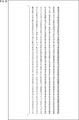
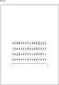
- FIG. 1 is a diagram illustrating the first MIP method.
- the first MIP method is a method for generating a predicted image of MIP proposed in Reference REF3 (JVET-P2001-v14).
- predMip [x] [y] ((( ⁇ mWeight [i] [y * predSize + x] * p [i]) + oW) >> sW) + pTemp [0] ⁇ ⁇ ⁇ (258)
- equation (258) the variable oW is calculated according to the following equation described as equation (257) in reference REF3.
- a ⁇ B and A >> B represent that A is shifted left and right by the B bit, respectively.
- PredMip [x] [y] represents the pixel (pixel value) where the horizontal position of the predicted image is x and the vertical position is y.
- the pixels of the predicted image are also called predicted pixels.
- the weight matrix mWeight [i] [j] set according to the MipSizeId and the modeId, the shift amount sW, and the offset factor fO are used. Then, MIP is performed and the pixels predMip [x] [y] of the predicted image are generated.
- p [i] represents the amount of change in the pixel (pixel value) pTemp [i] in the current prediction block.
- p [i] is the amount of change in the pixel pTemp [i] based on the pixel pTemp [0] on the upper left of the current prediction block.
- the offset factor fO is a coefficient related to the sum ⁇ p [i] of the amount of change p [i] of the pixel value.
- the shift amount sW is set according to MipSizeId and modeId according to Table 23 described in Reference REF3.
- the offset factor fO is set according to MipSizeId and modeId according to Table 24 described in Reference REF3.
- variable sW is derived using mipSizeId and modeId as specified in Table 8-5.” Is described, but “Table 8-5" is an error of "Table 23”. Further, in reference REF3, "The variable fO is derived using mipSizeId and modeId as specified in Table 8-6.” Is described, but “Table 8-6” is an error of "Table 24".
- reference REF11 JVET-P0625-v2
- fO offset factor
- the offset factor fO can be multiplied by a shift operation.
- the processing of MIP can be simplified.
- the offset factor fO is reset according to the MipSizeId and modeId as in the case of using the current Table 24. It is necessary and the processing becomes complicated.
- the first MIP method when the first MIP method is implemented by hardware, a selector for switching the offset factor fO is required, which increases the circuit scale.
- a selector for switching the offset factor fO when implementing the first MIP method by software, it is necessary to prepare a table in which the offset factor fO expressed by the power of 2 is defined and refer to that table, which reduces the processing speed. To do.
- MIP is performed using the offset factor fO set to a fixed value. That is, for example, the operations of equations (258) and (257) are changed according to the offset factor fO set to a fixed value, and the predicted image of MIP is generated according to the changed operations.
- the offset factor fO set to a fixed value as appropriate is also referred to as a fixed offset coefficient.
- the fixed offset coefficient is an offset factor fO set to a fixed value, it is a coefficient related to the sum ⁇ p [i] of the amount of change p [i] of the pixel value, like the offset factor fO.
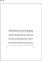
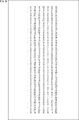
- FIG. 2 is a diagram illustrating the second MIP method.
- the offset factor fO of the equation (257) for generating the predicted image of MIP proposed in Reference REF3 is set to the fixed offset coefficient which is a fixed value.
- the fixed value to be the fixed offset coefficient for example, a value in which the range of the weight matrix mWeight [i] [j] is set to a predetermined range can be adopted.
- the weight matrix mWeight [i] [j] changes from the value described in reference REF3.
- a value can be adopted so that the range of the weight matrix mWeight [i] [j] after the change falls within a predetermined range.
- a value represented by a power of 2 or a value represented by the sum of powers of 2 can be adopted.
- the calculation accuracy is improved when the value represented by the sum of the powers of 2 is adopted rather than the value represented by the power of 2, that is, the MIP.
- the prediction error of the prediction image can be reduced.
- the shift amount sW of Eqs. (258) and Eq. (257) for generating the predicted image of MIP proposed in Reference REF3 is further set to a fixed shift amount which is a fixed value. Can be done.
- the fixed shift amount for example, one of three (types) shift amounts sW of 5, 6 and 7 specified in Table 23 of Reference REF3 can be adopted.
- the weight matrix mWeight depends on the fixed offset coefficient and the three shift amounts sW defined in Table 23 of Reference REF3, or according to the fixed offset coefficient and the fixed shift amount. [i] [j] are changed from the values described in reference REF3.
- the predicted pixel predMip [x] [y] obtained when the offset factor fO and the shift amount sW are adopted that is, the predicted pixel predMip [x] [y] obtained according to the reference REF3 (of the predicted image of MIP). It is also called the standard predicted pixel predMip [x] [y].
- the predicted pixels obtained when the fixed offset coefficient and the fixed shift amount are adopted (hereinafter, also referred to as fixed predicted pixels), that is, the offset factors fO of the equations (258) and (257).
- the predicted pixel predMip [x] [y] obtained according to the equation in which the shift amount sW is replaced with the fixed offset coefficient and the fixed shift amount, respectively becomes a value close to the standard predicted pixel predMip [x] [y].
- the weight matrix mWeight [i] [j] described in Reference REF3 is changed according to the fixed offset coefficient and the fixed shift amount.
- the changed weight matrix mWeight [i] [j] can be contained in a range that can be represented by 7 bits of 0 to 127.
- a predicted image of MIP is generated according to an operation including the changed weight matrix mWeight [i] [j].
- the offset factor fO of Eqs. (258) and Eq. (257) and the shift amount sW are fixed regardless of the combination of MipSizeId and modeId, which simplifies MIP processing. can do.
- the selector for switching the offset factor fO and the shift amount sW becomes unnecessary, and the increase in the circuit scale can be suppressed.
- the second MIP method is implemented by software, it is not necessary to refer to Table 24 or Table 23, and the decrease in processing speed is suppressed as compared with the case of referring to Table 24 or Table 23. be able to.
- the fixed offset coefficient a value represented by a power of 2 other than 32 or a value represented by the sum of powers of 2 other than 48 and 96 can be adopted. Further, as the fixed shift amount, values other than 5, 6, and 7 can be adopted.
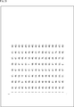
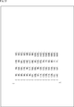
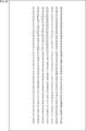
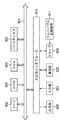
- FIG. 3 is a diagram for explaining the MIP when 48 is adopted as the fixed offset coefficient and 5 is adopted as the fixed shift amount.
- the sum sum ⁇ p [i] of the amount of change in the pixel value p [i] is calculated.
- the multiplication 48 * ( ⁇ p [i]) of the sum ⁇ p [i] of the amount of change p [i] of the pixel value and the fixed offset coefficient 48 is the shift operation (sum ⁇ 5) and (sum ⁇ 5) of the sum sum. It is performed by sum ⁇ 4) and the addition of the results of its shift operations (sum ⁇ 5) and (sum ⁇ 4).
- the variable oW in Eq. (257) is calculated.
- M represents MipSizeId
- m represents modeId
- the weight matrix mWeight [i] [j] when the fixed offset coefficient and the fixed shift amount are adopted is also referred to as a fixed weight matrix mWeight [i] [j].
- the i + 1th value from the left and the j + 1th value from the top represent the fixed weight matrix mWeight [i] [j]. The same applies to the following figures.
- the calculation is performed using the fixed offset coefficient and the fixed shift amount, and within the range where the technical effect is appropriately achieved. If there is, it can be changed as appropriate.
- the predicted image can be appropriately changed within a range in which technical effects such as ensuring a predetermined prediction accuracy or higher can be obtained.
- the approximation level means the degree to which the fixed prediction pixel predMip [x] [y] is approximated to the true value of the fixed prediction pixel predMip [x] [y] or the standard prediction pixel predMip [x] [y]. ..
- the fixed predicted pixel predMip [x] [y] means the predicted pixel (pixel value) obtained by MIP using the fixed offset coefficient and the fixed shift amount.
- the standard prediction pixel predMip [x] [y] means a prediction pixel obtained by MIP using the offset factor fO and the shift amount sW described in Reference REF3.
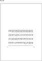
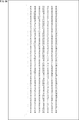
- FIG. 34 is a diagram for explaining the MIP when 96 is adopted as the fixed offset coefficient and 6 is adopted as the fixed shift amount.
- the sum sum ⁇ p [i] of the amount of change in the pixel value p [i] is calculated.
- the multiplication 96 * ( ⁇ p [i]) of the sum ⁇ p [i] of the amount of change p [i] of the pixel value and 96 which is the fixed offset coefficient is the sum shift operation (sum ⁇ 6) and ( It is performed by sum ⁇ 5) and the addition of the results of its shift operations (sum ⁇ 6) and (sum ⁇ 5).
- the variable oW in Eq. (257) is calculated.
- FIG. 65 is a block diagram showing a configuration example of an embodiment of an image processing system to which the present technology is applied.
- the image processing system 10 has an image processing device as an encoder 11 and an image processing device as a decoder 51.
- the encoder 11 encodes the original image to be coded supplied to the encoder 11 and outputs a coded bit stream obtained by the coding.
- the coded bit stream is supplied to the decoder 51 via a recording medium or a transmission medium (not shown).
- the decoder 51 decodes the coded bit stream supplied to the decoder 51 and outputs the decoded image obtained by the decoding.
- FIG. 66 is a block diagram showing a configuration example of the encoder 11 of FIG. 65.
- the encoder 11 has an A / D conversion unit 21, a sorting buffer 22, a calculation unit 23, an orthogonal conversion unit 24, a quantization unit 25, a lossless coding unit 26, and a storage buffer 27. Further, the encoder 11 includes an inverse quantization unit 28, an inverse orthogonal transform unit 29, a calculation unit 30, a frame memory 32, a selection unit 33, an intra prediction unit 34, a motion prediction compensation unit 35, a prediction image selection unit 36, and a rate. It has a control unit 37. Further, the encoder 11 has a deblock filter 31a, an adaptive offset filter 41, and an ALF (adaptive loop filter) 42.
- ALF adaptive loop filter
- the encoder 11 can be configured without providing the A / D conversion unit 21.
- the sorting buffer 22 sorts the frames of the original image in the order of coding (decoding) from the display order according to the GOP (Group Of Picture), and the calculation unit 23, the intra prediction unit 34, and the motion prediction compensation unit 35. Supply to.
- GOP Group Of Picture
- the calculation unit 23 subtracts the predicted image supplied from the intra prediction unit 34 or the motion prediction compensation unit 35 via the prediction image selection unit 36 from the original image from the sorting buffer 22, and the residual obtained by the subtraction. (Predicted residual) is supplied to the orthogonal conversion unit 24.
- the orthogonal transform unit 24 performs orthogonal transform such as discrete cosine transform and Karhunen-Loève transform on the residual supplied from the arithmetic unit 23, and supplies the orthogonal transform coefficient obtained by the orthogonal transform to the quantization unit 25. To do.
- the quantization unit 25 quantizes the orthogonal transformation coefficient supplied from the orthogonal transform unit 24.
- the quantization unit 25 sets the quantization parameter based on the target value (code amount target value) of the code amount supplied from the rate control unit 37, and performs the quantization of the orthogonal transformation coefficient.
- the quantization unit 25 supplies the coded data, which is the quantized orthogonal conversion coefficient, to the lossless coding unit 26.
- the lossless coding unit 26 encodes the quantized orthogonal transformation coefficient as the coded data from the quantization unit 25 by a predetermined lossless coding method.
- the lossless coding unit 26 acquires the coding information necessary for decoding by the decoding device 170 from each block among the coding information related to the predictive coding in the encoder 11.
- the coding information for example, the prediction mode of intra-prediction or inter-prediction, motion information such as motion vector, code amount target value, quantization parameter, picture type (I, P, B), deblock filter 31a. And the filter parameters of the adaptive offset filter 41 and the like.
- the prediction mode can be acquired from the intra prediction unit 34 and the motion prediction compensation unit 35.
- the motion information can be acquired from the motion prediction compensation unit 35.
- the filter parameters of the deblock filter 31a and the adaptive offset filter 41 can be obtained from the deblock filter 31a and the adaptive offset filter 41, respectively.
- the lossless coding unit 26 uses variable length coding such as CAVLC (Context-Adaptive Variable Length Coding) or CABAC (Context-Adaptive Binary Arithmetic Coding), arithmetic coding, or other lossless coding method for the coding information.
- variable length coding such as CAVLC (Context-Adaptive Variable Length Coding) or CABAC (Context-Adaptive Binary Arithmetic Coding), arithmetic coding, or other lossless coding method for the coding information.
- a coded bit stream containing the coded and coded coded information and the coded data from the quantization unit 25 is generated and supplied to the storage buffer 27.
- the above-mentioned calculation unit 23 or lossless coding unit 26 constitutes a coding unit that encodes an image, and the processing (process) performed by the coding unit is the coding process.
- the storage buffer 27 temporarily stores the coded bit stream supplied from the lossless coding unit 26.
- the coded bit stream stored in the storage buffer 27 is read out and transmitted at a predetermined timing.
- the coded data which is the orthogonal transformation coefficient quantized in the quantization unit 25, is supplied to the lossless coding unit 26 as well as to the inverse quantization unit 28.
- the inverse quantization unit 28 dequantizes the quantized orthogonal transformation coefficient by a method corresponding to the quantization by the quantization unit 25, and the orthogonal transformation coefficient obtained by the inverse quantization is transmitted to the inverse orthogonal transform unit 29. Supply.
- the inverse orthogonal transform unit 29 converts the orthogonal transform coefficient supplied from the inverse orthogonal transform unit 28 into an orthogonal transform by a method corresponding to the orthogonal transform process by the orthogonal transform unit 24, and obtains the residual obtained as a result of the inverse orthogonal transform. , Supply to the arithmetic unit 30.
- the calculation unit 30 adds the predicted image supplied from the intra prediction unit 34 or the motion prediction compensation unit 35 via the prediction image selection unit 36 to the residual supplied from the inverse orthogonal transform unit 29, whereby the original image is added. Obtain (a part of) the decoded image obtained by decoding the image and output it.
- the decoded image output by the calculation unit 30 is supplied to the deblock filter 31a or the frame memory 32.
- the frame memory 32 temporarily stores the decoded image supplied from the calculation unit 30, the deblocking filter 31a supplied from the ALF 42, the adaptive offset filter 41, and the decoded image (filter image) to which the ALF 42 is applied. ..
- the decoded image stored in the frame memory 32 is supplied to the selection unit 33 as a reference image used for generating the predicted image at a necessary timing.
- the selection unit 33 selects the supply destination of the reference image supplied from the frame memory 32.
- the selection unit 33 supplies the reference image supplied from the frame memory 32 to the intra prediction unit 34.
- the motion prediction compensation unit 35 performs inter-prediction, the selection unit 33 supplies the reference image supplied from the frame memory 32 to the motion prediction compensation unit 35.
- the intra prediction unit 34 performs intra prediction (in-screen prediction) using the original image supplied from the sorting buffer 22 and the reference image supplied from the frame memory 32 via the selection unit 33.
- the intra prediction unit 34 selects the optimum intra prediction prediction mode based on a predetermined cost function, and transmits the prediction image generated from the reference image in the optimum intra prediction prediction mode to the prediction image selection unit 36. Supply. Further, the intra prediction unit 34 appropriately supplies the prediction mode of the intra prediction selected based on the cost function to the lossless coding unit 26 and the like.
- the motion prediction compensation unit 35 performs motion prediction using the original image supplied from the sorting buffer 22 and the reference image supplied from the frame memory 32 via the selection unit 33. Further, the motion prediction compensation unit 35 performs motion compensation according to the motion vector detected by the motion prediction, and generates a prediction image.
- the motion prediction compensation unit 35 performs inter-prediction in a plurality of inter-prediction prediction modes prepared in advance, and generates a prediction image from the reference image.
- the motion prediction compensation unit 35 selects the optimum inter-prediction prediction mode from a plurality of inter-prediction prediction modes based on a predetermined cost function. Further, the motion prediction compensation unit 35 supplies the prediction image generated in the prediction mode of the optimum inter-prediction to the prediction image selection unit 36.
- the motion prediction compensation unit 35 includes an optimum inter-prediction prediction mode selected based on the cost function, a motion vector required for decoding the coded data encoded in the inter-prediction prediction mode, and the like.
- the motion information and the like of the above are supplied to the reversible coding unit 26.
- the prediction image selection unit 36 selects the supply source of the prediction image to be supplied to the calculation unit 23 and the calculation unit 30 from the intra prediction unit 34 and the motion prediction compensation unit 35, and is supplied from the selected supply source.
- the predicted image is supplied to the calculation unit 23 and the calculation unit 30.
- the rate control unit 37 controls the rate of the quantization operation of the quantization unit 25 based on the code amount of the coded bit stream stored in the storage buffer 27 so that overflow or underflow does not occur. That is, the rate control unit 37 sets a target code amount of the coded bit stream and supplies it to the quantization unit 25 so that overflow and underflow of the storage buffer 27 do not occur.
- the deblock filter 31a applies the deblock filter to the decoded image from the calculation unit 30 as necessary, and the deblock filter is applied to the decoded image (filter image), or the deblock filter is not applied.
- the decoded image is supplied to the adaptive offset filter 41.
- the adaptive offset filter 41 applies the adaptive offset filter to the decoded image from the deblock filter 31a as necessary, and the decoded image (filter image) to which the adaptive offset filter is applied, or the adaptive offset filter is applied. No decoded image is supplied to ALF42.
- the ALF 42 applies the ALF to the decoded image from the adaptive offset filter 41 as necessary, and supplies the decoded image to which the ALF is applied or the decoded image to which the ALF is not applied to the frame memory 32.
- FIG. 67 is a flowchart illustrating an example of coding processing of the encoder 11 of FIG. 66.
- each step of the coding process shown in FIG. 67 is an order for convenience of explanation, and each step of the actual coding process is performed in a necessary order in parallel as appropriate. The same applies to the processing described later.
- step S11 the A / D conversion unit 21 A / D-converts the original image and supplies it to the sorting buffer 22, and the process proceeds to step S12.
- step S12 the sorting buffer 22 stores the original images from the A / D conversion unit 21, sorts them in the coding order, and outputs them, and the process proceeds to step S13.
- step S13 the intra prediction unit 34 makes an intra prediction (intra prediction step), and the process proceeds to step S14.
- step S14 the motion prediction compensation unit 35 performs inter-prediction for motion prediction and motion compensation, and the process proceeds to step S15.
- step S15 the prediction image selection unit 36 determines the optimum prediction mode based on each cost function obtained by the intra prediction unit 34 and the motion prediction compensation unit 35. Then, the prediction image selection unit 36 selects and outputs a prediction image of the optimum prediction mode from the prediction image generated by the intra prediction unit 34 and the prediction image generated by the motion prediction compensation unit 35, and outputs the prediction image. The process proceeds from step S15 to step S16.
- step S16 the calculation unit 23 calculates the residual between the target image to be encoded, which is the original image output by the sorting buffer 22, and the prediction image output by the prediction image selection unit 36, and the orthogonal transformation unit 24 calculates the residual.
- the process proceeds to step S17.
- step S17 the orthogonal transform unit 24 orthogonally transforms the residual from the arithmetic unit 23, supplies the orthogonal transform coefficient obtained as a result to the quantization unit 25, and the process proceeds to step S18.
- step S18 the quantization unit 25 quantizes the orthogonal conversion coefficient from the orthogonal conversion unit 24, and supplies the quantization coefficient obtained by the quantization to the reversible coding unit 26 and the inverse quantization unit 28.
- the process proceeds to step S19.
- step S19 the inverse quantization unit 28 inversely quantizes the quantization coefficient from the quantization unit 25, supplies the orthogonal conversion coefficient obtained as a result to the inverse orthogonal conversion unit 29, and the process proceeds to step S20. move on.
- step S20 the inverse orthogonal transform unit 29 reverse-orthogonally transforms the orthogonal transform coefficient from the inverse quantization unit 28, supplies the residual obtained as a result to the arithmetic unit 30, and the process proceeds to step S21. ..
- step S21 the calculation unit 30 adds the residual from the inverse orthogonal transform unit 29 and the prediction image output by the prediction image selection unit 36, and the calculation unit 23 is the target of the residual calculation. Generate a decoded image corresponding to the image.
- the calculation unit 30 supplies the decoded image to the deblock filter 31a, and the process proceeds from step S21 to step S22.
- step S22 the deblock filter 31a applies the deblock filter to the decoded image from the calculation unit 30, supplies the filter image obtained as a result to the adaptive offset filter 41, and the process proceeds to step S23. ..
- step S23 the adaptive offset filter 41 applies the adaptive offset filter to the filter image from the deblock filter 31a, supplies the filter image obtained as a result to the ALF 42, and the process proceeds to step S24.
- step S24 ALF 42 applies ALF to the filter image from the adaptive offset filter 41, supplies the filter image obtained as a result to the frame memory 32, and the process proceeds to step S25.
- step S25 the frame memory 32 stores the filter image supplied from the ALF 42, and the process proceeds to step S26.
- the filter image stored in the frame memory 32 is used as a reference image from which the predicted image is generated in steps S13 and S14.
- the lossless coding unit 26 encodes the coded data which is the quantization coefficient from the quantization unit 25, and generates a coded bit stream including the coded data. Further, the lossless coding unit 26 includes the quantization parameters used for the quantization in the quantization unit 25, the prediction mode obtained by the intra prediction in the intra prediction unit 34, and the inter prediction in the motion prediction compensation unit 35. If necessary, the coding information such as the prediction mode and motion information obtained in 1 and the filter parameters of the lossless filter 31a and the adaptive offset filter 41 is encoded and included in the encoded bit stream.
- the lossless coding unit 26 supplies the coded bit stream to the storage buffer 27, and the process proceeds from step S26 to step S27.
- step S27 the storage buffer 27 stores the coded bit stream from the lossless coding unit 26, and the process proceeds to step S28.
- the coded bit stream stored in the storage buffer 27 is appropriately read and transmitted.
- step S28 the rate control unit 37 determines the quantum of the quantization unit 25 so that overflow or underflow does not occur based on the code amount (generated code amount) of the coded bit stream stored in the storage buffer 27.
- the rate of the conversion operation is controlled, and the coding process ends.
- FIG. 68 is a block diagram showing a detailed configuration example of the decoder 51 of FIG. 65.
- the decoder 51 includes a storage buffer 61, a reversible decoding unit 62, an inverse quantization unit 63, an inverse orthogonal conversion unit 64, a calculation unit 65, a sorting buffer 67, and a D / A conversion unit 68. Further, the decoder 51 includes a frame memory 69, a selection unit 70, an intra prediction unit 71, a motion prediction compensation unit 72, and a selection unit 73. The decoder 51 also includes a deblock filter 31b, an adaptive offset filter 81, and an ALF 82.
- the storage buffer 61 temporarily stores the coded bit stream transmitted from the encoder 11 and supplies the coded bit stream to the reversible decoding unit 62 at a predetermined timing.
- the lossless decoding unit 62 receives the coded bit stream from the storage buffer 61 and decodes it by a method corresponding to the coding method of the lossless coding unit 26 of FIG.
- the lossless decoding unit 62 supplies the quantization coefficient as the coding data included in the decoding result of the coded bit stream to the inverse quantization unit 63.
- the reversible decoding unit 62 has a function of performing parsing.
- the reversible decoding unit 62 parses the necessary coding information included in the decoding result of the coded bit stream, and supplies the coding information to the intra prediction unit 71, the motion prediction compensation unit 72, the deblock filter 31b, and the adaptive offset filter. 81 Supply to other necessary blocks.
- the inverse quantization unit 63 dequantizes the quantization coefficient as the coded data from the reversible decoding unit 62 by a method corresponding to the quantization method of the quantization unit 25 of FIG. 66, and is obtained by the inverse quantization.
- the orthogonal conversion coefficient is supplied to the inverse orthogonal conversion unit 64.
- the inverse orthogonal transform unit 64 reverse-orthogonally transforms the orthogonal transform coefficient supplied from the inverse quantization unit 63 by a method corresponding to the orthogonal transform method of the orthogonal transform unit 24 of FIG. 66, and obtains a residual obtained as a result. It is supplied to the arithmetic unit 65.
- the prediction image is supplied from the intra prediction unit 71 or the motion prediction compensation unit 72 via the selection unit 73.
- the calculation unit 65 adds the residual from the inverse orthogonal transform unit 64 and the predicted image from the selection unit 73 to generate a decoded image and supplies it to the deblock filter 31b.
- the above-mentioned reversible decoding unit 62 or calculation unit 65 constitutes a decoding unit for decoding an image, and the process (process) performed by the decoding unit is the decoding process.
- the sorting buffer 67 temporarily stores the decoded images supplied from the ALF 82, sorts the frames (pictures) of the decoded images in the order of encoding (decoding) order, and supplies them to the D / A conversion unit 68. ..
- the decoder 51 can be configured without providing the D / A conversion unit 68.
- the frame memory 69 temporarily stores the decoded image supplied from the ALF 82. Further, the frame memory 69 uses the decoded image as a reference image to be used for generating the predicted image at a predetermined timing or based on an external request of the intra prediction unit 71, the motion prediction compensation unit 72, or the like, and the selection unit 70. Supply to.
- the selection unit 70 selects the supply destination of the reference image supplied from the frame memory 69.
- the selection unit 70 supplies the reference image supplied from the frame memory 69 to the intra prediction unit 71. Further, when decoding the image encoded by the inter-prediction, the selection unit 70 supplies the reference image supplied from the frame memory 69 to the motion prediction compensation unit 72.
- the intra prediction unit 71 uses a reference image supplied from the frame memory 69 via the selection unit 70 according to the prediction mode included in the coding information supplied from the reversible decoding unit 62, and the intra prediction unit 34 of FIG. Make the same intra-prediction as. Then, the intra prediction unit 71 supplies the prediction image obtained by the intra prediction to the selection unit 73.
- the motion prediction compensation unit 72 is supplied from the frame memory 69 via the selection unit 70 in the same manner as the motion prediction compensation unit 35 of FIG. 66 according to the prediction mode included in the coding information supplied from the reversible decoding unit 62. Inter-prediction is performed using the reference image. The inter-prediction is performed by using motion information or the like included in the coding information supplied from the reversible decoding unit 62 as necessary.
- the motion prediction compensation unit 72 supplies the prediction image obtained by the inter-prediction to the selection unit 73.
- the selection unit 73 selects the prediction image supplied from the intra prediction unit 71 or the prediction image supplied from the motion prediction compensation unit 72, and supplies the prediction image to the calculation unit 65.
- the deblock filter 31b applies the deblock filter to the decoded image from the calculation unit 65 according to the filter parameters included in the coding information supplied from the reversible decoding unit 62.
- the deblock filter 31b supplies a decoded image (filter image) to which the deblock filter is applied or a decoded image to which the deblock filter is not applied to the adaptive offset filter 81.
- the adaptive offset filter 81 applies the adaptive offset filter to the decoded image from the deblock filter 31b as necessary according to the filter parameters included in the coding information supplied from the reversible decoding unit 62.
- the adaptive offset filter 81 supplies the decoded image (filter image) to which the adaptive offset filter is applied or the decoded image to which the adaptive offset filter is not applied to the ALF 82.
- the ALF 82 applies ALF to the decoded image from the adaptive offset filter 81 as necessary, and applies the decoded image to which ALF is applied or the decoded image to which ALF is not applied to the sorting buffer 67 and the frame memory 69. Supply to.
- FIG. 69 is a flowchart illustrating an example of decoding processing of the decoder 51 of FIG. 68.
- step S51 the storage buffer 61 temporarily stores the coded bit stream transmitted from the encoder 11 and supplies it to the reversible decoding unit 62 as appropriate, and the process proceeds to step S52.
- step S52 the reversible decoding unit 62 receives and decodes the coded bit stream supplied from the storage buffer 61, and dequantizes the quantization coefficient as the coded data included in the decoding result of the coded bit stream. It is supplied to the unit 63.
- the reversible decoding unit 62 parses the coding information included in the decoding result of the coded bit stream. Then, the reversible decoding unit 62 supplies the necessary coding information to the intra prediction unit 71, the motion prediction compensation unit 72, the deblock filter 31b, the adaptive offset filter 81, and other necessary blocks.
- step S52 the process proceeds from step S52 to step S53, and the intra prediction unit 71 or the motion prediction compensation unit 72 is supplied from the frame memory 69 via the selection unit 70 and the reversible decoding unit 62.
- Intra-prediction or inter-prediction to generate a prediction image is performed according to the coded information (intra-prediction step or inter-prediction step).
- the intra prediction unit 71 or the motion prediction compensation unit 72 supplies the prediction image obtained by the intra prediction or the inter prediction to the selection unit 73, and the process proceeds from step S53 to step S54.
- step S54 the selection unit 73 selects the prediction image supplied from the intra prediction unit 71 or the motion prediction compensation unit 72, supplies the prediction image to the calculation unit 65, and the process proceeds to step S55.
- step S55 the inverse quantization unit 63 inversely quantizes the quantization coefficient from the reversible decoding unit 62, supplies the orthogonal conversion coefficient obtained as a result to the inverse orthogonal transformation unit 64, and the process proceeds to step S56. move on.
- step S56 the inverse orthogonal transform unit 64 reverse-orthogonally transforms the orthogonal transform coefficient from the inverse quantization unit 63, supplies the residual obtained as a result to the arithmetic unit 65, and the process proceeds to step S57. ..
- step S57 the calculation unit 65 generates a decoded image by adding the residual from the inverse orthogonal transform unit 64 and the predicted image from the selection unit 73. Then, the calculation unit 65 supplies the decoded image to the deblock filter 31b, and the process proceeds from step S57 to step S58.
- step S58 the deblock filter 31b applies the deblock filter to the decoded image from the arithmetic unit 65 according to the filter parameters included in the coding information supplied from the reversible decoding unit 62.
- the deblock filter 31b supplies the filter image obtained as a result of applying the deblock filter to the adaptive offset filter 81, and the process proceeds from step S58 to step S59.
- step S59 the adaptive offset filter 81 applies the adaptive offset filter to the filter image from the deblock filter 31b according to the filter parameters included in the coding information supplied from the reversible decoding unit 62.
- the adaptive offset filter 81 supplies the filter image obtained as a result of applying the adaptive offset filter to the ALF 82, and the process proceeds from step S59 to step S60.
- the ALF 82 applies the ALF to the filter image from the adaptive offset filter 81, supplies the filter image obtained as a result to the sorting buffer 67 and the frame memory 69, and the process proceeds to step S61.
- step S61 the frame memory 69 temporarily stores the filter image supplied from ALF82, and the process proceeds to step S62.
- the filter image (decoded image) stored in the frame memory 69 is used as a reference image from which the predicted image is generated in the intra-prediction or inter-prediction in step S53.
- step S62 the sorting buffer 67 sorts the filter images supplied from ALF82 in the display order and supplies them to the D / A conversion unit 68, and the process proceeds to step S63.
- step S63 the D / A conversion unit 68 D / A-converts the filter image from the sorting buffer 67, and the decoding process ends.
- the filter image (decoded image) after D / A conversion is output and displayed on a display (not shown).
- the intra prediction performed by the intra prediction unit 34 of FIG. 66 and the intra prediction unit 71 of FIG. 68 includes MIP.
- the generation of the prediction image of MIP can be performed by the second MIP method.
- This technology can be applied to any image coding / decoding method. That is, as long as it does not contradict the above-mentioned technology, the specifications of various processes related to image coding / decoding such as conversion (inverse transformation), quantization (inverse quantization), coding (decoding), and prediction are arbitrary. It is not limited to the example. In addition, some of these processes may be omitted as long as they do not contradict the present technology described above.
- a "block” (not a block indicating a processing unit) used in the description as a partial area of an image (picture) or a processing unit indicates an arbitrary partial area in the picture unless otherwise specified. Its size, shape, characteristics, etc. are not limited.
- “block” includes TB (Transform Block), TU (Transform Unit), PB (Prediction Block), PU (Prediction Unit), SCU (Smallest Coding Unit), CU ( Includes any partial area (processing unit) such as Coding Unit), LCU (Largest Coding Unit), CTB (Coding Tree Block), CTU (Coding Tree Unit), conversion block, subblock, macroblock, tile, or slice. It shall be.
- the data unit in which the various information described above is set and the data unit targeted by the various processes are arbitrary and are not limited to the above-mentioned example.
- these information and processes are TU (Transform Unit), TB (Transform Block), PU (Prediction Unit), PB (Prediction Block), CU (Coding Unit), LCU (Largest Coding Unit), and subblock, respectively.
- Blocks, tiles, slices, pictures, sequences, or components, or data in those data units may be targeted.
- this data unit can be set for each information or process, and it is not necessary that the data unit of all the information or process is unified.
- the storage location of these information is arbitrary, and may be stored in the header, parameter set, or the like of the above-mentioned data unit. Further, it may be stored in a plurality of places.
- control information related to the present technology described above may be transmitted from the coding side to the decoding side.
- control information for example, enabled_flag
- control information indicating an object to which the present technology is applied (or an object to which the present technology is not applied) may be transmitted.
- control information that specifies the block size (upper limit, lower limit, or both) to which the present technology is applied (or permission or prohibition of application), a frame, a component, a layer, or the like may be transmitted.
- the block size may be specified directly, but also the block size may be specified indirectly.
- the block size may be specified using identification data that identifies the size.
- the block size may be specified by the ratio or difference with the size of the reference block (for example, LCU, SCU, etc.).
- the designation of the block size also includes the designation of the range of the block size (for example, the designation of the range of the allowable block size).
- identification data is information for identifying a plurality of states, and includes “flag” and other names. Further, the “identification data” includes not only information used for identifying two states of true (1) or false (0), but also information capable of identifying three or more states. Therefore, the value that can be taken by this "identification data” may be, for example, 2 values of 1/0 or 3 or more values. That is, the number of bits constituting this "identification data” is arbitrary, and may be 1 bit or a plurality of bits. Further, the identification data is assumed to include not only the identification data in the bit stream but also the difference information of the identification data with respect to a certain reference information in the bit stream. "Data" includes not only the information but also the difference information with respect to the reference information.
- various information (metadata, etc.) regarding the coded data may be transmitted or recorded in any form as long as it is associated with the coded data.
- the term "associate" means, for example, to make the other data available (linkable) when processing one data. That is, the data associated with each other may be combined as one data or may be individual data.
- the information associated with the coded data (image) may be transmitted on a transmission path different from the coded data (image).
- the information associated with the coded data (image) may be recorded on a recording medium (or another recording area of the same recording medium) different from the coded data (image). Good.
- this "association" may be a part of the data, not the entire data.
- the image and the information corresponding to the image may be associated with each other in an arbitrary unit such as a plurality of frames, one frame, or a part within the frame.
- This technology provides a device or any configuration that constitutes a system, for example, a processor as a system LSI (Large Scale Integration), a module that uses a plurality of processors, a unit that uses a plurality of modules, and other functions in the unit. It can also be implemented as an added set or the like (that is, a part of the configuration of the device).
- LSI Large Scale Integration
- FIG. 70 is a block diagram showing a configuration example of an embodiment of a computer in which a program for executing all or a part of the above-mentioned series of processes is installed.
- the program can be recorded in advance on the hard disk 905 or ROM 903 as a recording medium built in the computer.
- the program can be stored (recorded) in the removable recording medium 911 driven by the drive 909.
- a removable recording medium 911 can be provided as so-called package software.
- examples of the removable recording medium 911 include a flexible disc, a CD-ROM (Compact Disc Read Only Memory), an MO (Magneto Optical) disc, a DVD (Digital Versatile Disc), a magnetic disc, and a semiconductor memory.
- the program can be installed on the computer from the removable recording medium 911 as described above, or can be downloaded to the computer via a communication network or a broadcasting network and installed on the built-in hard disk 905. That is, for example, the program transfers wirelessly from a download site to a computer via an artificial satellite for digital satellite broadcasting, or transfers to a computer by wire via a network such as LAN (Local Area Network) or the Internet. be able to.
- LAN Local Area Network
- the computer has a built-in CPU (Central Processing Unit) 902, and the input / output interface 910 is connected to the CPU 902 via the bus 901.
- CPU Central Processing Unit
- the CPU 902 executes a program stored in the ROM (Read Only Memory) 903 accordingly. .. Alternatively, the CPU 902 loads the program stored in the hard disk 905 into the RAM (Random Access Memory) 904 and executes it.
- ROM Read Only Memory
- the CPU 902 performs processing according to the above-mentioned flowchart or processing performed according to the above-mentioned block diagram configuration. Then, the CPU 902 outputs the processing result from the output unit 906, transmits it from the communication unit 908, and further records it on the hard disk 905, if necessary, via the input / output interface 910.
- the input unit 907 is composed of a keyboard, a mouse, a microphone, and the like. Further, the output unit 906 is composed of an LCD (Liquid Crystal Display), a speaker, or the like.
- LCD Liquid Crystal Display
- the processing performed by the computer according to the program does not necessarily have to be performed in chronological order in the order described as the flowchart. That is, the processing performed by the computer according to the program also includes processing executed in parallel or individually (for example, parallel processing or processing by an object).
- the program may be processed by one computer (processor) or may be distributed processed by a plurality of computers. Further, the program may be transferred to a distant computer and executed.
- the system means a set of a plurality of components (devices, modules (parts), etc.), and it does not matter whether all the components are in the same housing. Therefore, a plurality of devices housed in separate housings and connected via a network, and a device in which a plurality of modules are housed in one housing are both systems. ..
- this technology can have a cloud computing configuration in which one function is shared by a plurality of devices via a network and jointly processed.
- each step described in the above flowchart can be executed by one device or shared by a plurality of devices.
- one step includes a plurality of processes
- the plurality of processes included in the one step can be executed by one device or shared by a plurality of devices.
Landscapes
- Engineering & Computer Science (AREA)
- Multimedia (AREA)
- Signal Processing (AREA)
- Compression Or Coding Systems Of Tv Signals (AREA)
Abstract
本技術は、処理を単純化することができるようにする画像処理装置及び画像処理方法に関する。 符号化/復号の対象のカレント予測ブロックに対して行列演算を用いたイントラ予測である行列イントラ予測を行う際に、固定値に設定された、画素値の変化量の和にかかる係数を用いて、行列イントラ予測が行われ、カレント予測ブロックの予測画像が生成される。そして、予測画像を用いて、カレント予測ブロックが符号化/復号される。本技術は、例えば、画像の符号化及び復号を行う場合に適用することができる。
Description
本技術は、画像処理装置及び画像処理方法に関し、特に、例えば、処理を単純化することができるようにする画像処理装置及び画像処理方法に関する。
ITU-TとISO/IECとの共同の標準化団体であるJVET(Joint Video Experts Team)では、H.265/HEVCよりも符号化効率をさらに向上することを目的として、次世代の画像符号化方式であるVVC(Versatile Video Coding)の標準化作業が進められている。
VVCの標準化作業では、予測ブロックに対して行列演算を用いたイントラ予測である行列イントラ予測(MIP(Matrix-based intra prediction))を行うことが提案されている(例えば、非特許文献1を参照)。
MIPでは、パラメータ学習で求められた行列(ウエイトマトリクス)のパラメータが規定されており、その行列(のパラメータ)を用いた演算が行われる。
Benjamin Bross, Jianle Chen, Shan Liu, Versatile Video Coding (Draft 7), JVET-P2001-v14 (version 14 - date 2019-11-14)
MIPの演算(MIPで行われる演算)は、オフセットファクタfOを用いて行われる。オフセットファクタfOは、ビット精度を高くするために、行列のマトリクスサイズを表すMipSizeId及びMIPのモード番号を表すmodeIdに応じて変更される。
以上のように、MIPの演算では、MipSizeId及びmodeIdに応じて、オフセットファクタfOが変更されるため、MipSizeId及びmodeIdの組み合わせごとに、オフセットファクタfOを設定しなければならず、処理が複雑になる。
本技術は、このような状況に鑑みてなされたものであり、処理を単純化することができるようにするものである。
本技術の第1の画像処理装置は、符号化の対象のカレント予測ブロックに対して行列演算を用いたイントラ予測である行列イントラ予測を行う際に、固定値に設定された、画素値の変化量の和にかかる係数を用いて、前記行列イントラ予測を行い、前記カレント予測ブロックの予測画像を生成するイントラ予測部と、前記イントラ予測部により生成された前記予測画像を用いて、前記カレント予測ブロックを符号化する符号化部とを備える画像処理装置である。
本技術の第1の画像処理方法は、符号化の対象のカレント予測ブロックに対して行列演算を用いたイントラ予測である行列イントラ予測を行う際に、固定値に設定された、画素値の変化量の和にかかる係数を用いて、前記行列イントラ予測を行い、前記カレント予測ブロックの予測画像を生成するイントラ予測工程と、前記イントラ予測工程において生成された前記予測画像を用いて、前記カレント予測ブロックを符号化する符号化工程とを含む画像処理方法である。
本技術の第1の画像処理装置及び画像処理方法においては、符号化の対象のカレント予測ブロックに対して行列演算を用いたイントラ予測である行列イントラ予測を行う際に、固定値に設定された、画素値の変化量の和にかかる係数を用いて、前記行列イントラ予測が行われ、前記カレント予測ブロックの予測画像が生成される。そして、前記予測画像を用いて、前記カレント予測ブロックが符号化される。
本技術の第2の画像処理装置は、復号の対象のカレント予測ブロックに対して行列演算を用いたイントラ予測である行列イントラ予測を行う際に、固定値に設定された、画素値の変化量の和にかかる係数を用いて、前記行列イントラ予測を行い、前記カレント予測ブロックの予測画像を生成するイントラ予測部と、前記イントラ予測部により生成された前記予測画像を用いて、前記カレント予測ブロックを復号する復号部とを備える画像処理装置である。
本技術の第2の画像処理方法は、復号の対象のカレント予測ブロックに対して行列演算を用いたイントラ予測である行列イントラ予測を行う際に、固定値に設定された、画素値の変化量の和にかかる係数を用いて、前記行列イントラ予測を行い、前記カレント予測ブロックの予測画像を生成するイントラ予測工程と、前記イントラ予測工程において生成された前記予測画像を用いて、前記カレント予測ブロックを復号する復号工程とを含む画像処理方法である。
本技術の第2の画像処理装置及び画像処理方法においては、復号の対象のカレント予測ブロックに対して行列演算を用いたイントラ予測である行列イントラ予測を行う際に、固定値に設定された、画素値の変化量の和にかかる係数を用いて、前記行列イントラ予測が行われ、前記カレント予測ブロックの予測画像が生成される。そして、前記予測画像を用いて、前記カレント予測ブロックが復号される。
なお、画像処理装置は、独立した装置であっても良いし、1つの装置を構成している内部ブロックであっても良い。
また、画像処理装置は、コンピュータにプログラムを実行させることにより実現することができる。プログラムは、記録媒体に記録して、又は、伝送媒体を介して伝送することにより、提供することができる。
<参照文献>
本明細書で開示される範囲は、実施の形態の内容に限定されるものではなく、出願当時において公知となっている以下の参照文献REF1-REF11の内容も、参照により本明細書に組み込まれる。つまり、以下の参照文献REF1-REF11に記載されている内容もサポート要件について判断する際の根拠となる。さらに、参照文献REF1~REF11において参照している文献もサポート要件を判断する際の根拠となる。
例えば、Quad-Tree Block Structure、QTBT(Quad Tree Plus Binary Tree) Block Structure、MTT(Multi-type Tree) Block Structureが発明の詳細な説明において直接的に定義されていない場合でも、本開示の範囲内であり、請求の範囲のサポート要件を満たすものとする。また、例えば、パース(Parsing)、シンタクス(Syntax)、セマンティクス(Semantics)等の技術用語についても同様に、発明の詳細な説明において直接的に定義されていない場合でも、本開示の範囲内であり、請求の範囲のサポート要件を満たすものとする。
REF1:Recommendation ITU-T H.264 (04/2017) “Advanced video coding for generic audiovisual services", April 2017
REF2:Recommendation ITU-T H.265 (02/2018) “High efficiency video coding", February 2018
REF3:Benjamin Bross, Jianle Chen, Shan Liu, Versatile Video Coding (Draft 7), JVET-P2001-v14 (version 14 - date 2019-11-14)
REF4: Jianle Chen, Yan Ye, Seung Hwan Kim, Algorithm description for Versatile Video Coding and Test Model 7 (VTM 7), JVET-P2002-v1 (version 1 - date 2019-11-10)
REF5: JVET-N0217-v3: CE3: Affine linear weighted intra prediction (CE3-4.1, CE3-4.2) (version 7 - date 2019-01-17)
REF6: JVET-M0043-v2: CE3: Affine linear weighted intra prediction (test 1.2.1, test 1.2.2) (version 2 - date 2019-01-09)
REF7: JVET-O0408-v3: Non-CE3: On rounding shift of MIP (version 3 date 2019-07-04)
REF8: JVET-O0925-v3: Non-CE3: Simplifications of MIP (version 3 date 2019-07-04)
REF9: Kenji Kondo, Masaru Ikeda, Teruhiko Suzuki, Junyan Huo, Yanzhuo Ma, Fuzheng Yan, Shuai Wan, Yuanfang Yu, CE3-2: On rounding shift of MIP, JVET-P0056-v3 (version 3 - date 2019-10-03)
REF10: Junyan Huo, Haixin Wang, Yu Sun, Yanzhuo Ma, Shuai Wan, Fuzheng Yang. Yuanfang Yu, Yang Liu, Non-CE3: MIP simplification. JVET-P0136-v2 (version 3 - date 2019-10-04)
REF11: Thibaud Biatek, Adarsh K. Ramasubramonian, Geert Van der Auwera, Marta Karczewicz, Non-CE3: simplified MIP with power-of-two offset. JVET-P0625-v2 (version 2 - date 2019-10-02)
<定義>
隣接するとは、画素について言えば、注目するカレント画素に対して1画素分(1ライン分)隣接する場合だけでなく、複数画素分(複数ライン分)隣接する場合を含む。したがって、隣接する画素とは、カレント画素に直接隣接する1画素分の位置の画素の他、カレント画素に連続的に隣接する複数画素分の位置の画素を含む。また、隣接するブロックとは、注目するカレントブロックに直接隣接する1ブロック分の範囲のブロックの他、カレントブロックに連続的に隣接する複数ブロック分の範囲のブロックを含む。さらに、隣接するブロックとは、カレントブロックの近傍に位置するブロックをも必要に応じて含むことができる。
予測ブロックとは、イントラ予測やインター予測を行う際の処理単位となるブロック(PU(Prediction Unit))を意味し、予測ブロック内のサブブロックも含む。予測ブロック、直交変換ブロック(TU(Transform Unit))、符号化ブロック(CU(Coding Unit))が、同一のブロックに統一化されている場合、予測ブロック、直交変換ブロック、及び、符号化ブロックは、同一のブロックを意味する。直交変換ブロックとは、直交変換を行う際の処理単位となるブロックであり、符号化ブロックとは、符号化を行う際の処理単位となるブロックである。
イントラ予測モードとは、イントラ予測を行う際のモード番号、モード番号のインデクス、予測ブロックのブロックサイズ、予測ブロック内の処理単位となるサブブロックのサイズ等の、イントラ予測モードを導出する際に参照する変数(パラメータ)を包括して意味する。
行列イントラ予測モード(MIPモード)とは、MIPのモード番号、モード番号のインデクス、MIPの演算を行う際に用いる行列の種類、MIPの演算を行う際に用いる行列のマトリクスサイズの種類等の、行列イントラ予測モードを導出する際に参照する変数(パラメータ)を包括して意味する。
パラメータとは、符号化又は復号する際に必要となるデータの総称であり、典型的にはビットストリームのシンタクス、パラメータセット等である。さらに、パラメータは、導出過程で用いられる変数等を含む。MIPについては、MIPの演算を行う際に用いられる各種データがパラメータに該当する。例えば、REF3に記載されているオフセットファクタfO、シフト量sW、及び、ウエイトマトリクス(のコンポーネント)mWeight[i][j]等が、パラメータに該当する。
変更するとは、決められた内容を変えること、例えば、本出願日よりも前の日付を基準として公知文献に記載された内容を変えることを意味する。したがって、例えば、参照文献REF3に記載された内容(値、演算式、変数等)を基準にして、その内容と異なることは、変更に該当する。
本技術では、複数のパターンを識別する識別データを、画像を符号化して得られるビットストリームのシンタクスとして設定することができる。ビットストリームには、様々なパターンを識別する識別データを含めることができる。
ビットストリームに識別データを含める場合、そのビットストリームを復号するデコーダでは、識別データをパースして参照することにより、より効率的に処理を行うことが可能となる。
<第1のMIP法>
図1は、第1のMIP法を説明する図である。
第1のMIP法は、参照文献REF3(JVET-P2001-v14)で提案されているMIPの予測画像の生成方法である。
第1のMIP法では、参照文献REF3に式(258)として記載されている次式に従って、符号化/復号の対象の予測ブロックであるカレント予測ブロックの予測画像の(一部の)画素(の画素値)predMip[x][y]が生成される。
predMip[x][y] = ((( ΣmWeight[i][y * predSize + x]*p[i] ) + oW ) >> sW ) + pTemp[0]
・・・(258)
・・・(258)
式(258)において、変数oWは、参照文献REF3に式(257)として記載されている次式に従って算出される。
oW = ( 1 << ( sW - 1)) - fO * ( Σp[i] )
・・・(257)
・・・(257)
A<<B及びA>>Bは、Aを、Bビットだけ左シフト及び右シフトすることをそれぞれ表す。
式(258)及び式(257)における各変数については、参照文献REF3で説明されているため、その説明は、適宜省略する。
predMip[x][y]は、予測画像の横の位置がxで縦の位置がyの画素(の画素値)を表す。予測画像の画素を予測画素ともいう。
式(258)及び式(257)によれば、第1のMIP法では、MipSizeId及びmodeIdに応じて設定されたウエイトマトリクスmWeight[i][j]、シフト量sW、及び、オフセットファクタfOを用いて、MIPが行われ、予測画像の画素predMip[x][y]が生成される。
ここで、式(258)及び式(257)において、p[i]は、カレント予測ブロック内の画素(の画素値)pTemp[i]の変化量を表す。例えば、p[i]は、カレント予測ブロックの左上の画素pTemp[0]を基準とする画素pTemp[i]の変化量であり、例えば、式p[i] = pTemp[i + 1] - pTemp[0]、又は、式p[i] = pTemp[i] - pTemp[0]で表される。
式(257)において、オフセットファクタfOは、画素値の変化量p[i]の和Σp[i]にかかる係数になっている。
シフト量sWは、参照文献REF3に記載されているTable 23に従い、MipSizeId及びmodeIdに応じて設定される。オフセットファクタfOは、参照文献REF3に記載されているTable 24に従い、MipSizeId及びmodeIdに応じて設定される。
なお、参照文献REF3では、"The variable sW is derived using mipSizeId and modeId as specified in Table 8-5."と記載されているが、"Table 8-5"は、"Table 23"の誤記である。また、参照文献REF3では、"The variable fO is derived using mipSizeId and modeId as specified in Table 8-6."と記載されているが、"Table 8-6"は、"Table 24"の誤記である。
ところで、参照文献REF10(JVET-P0136-v2)では、参照文献REF3のTable 24を削除すること、すなわち、オフセットファクタfOを用いないことが提案されている。
また、参照文献REF11(JVET-P0625-v2)では、参照文献REF3のTable 24に定められるオフセットファクタfOとして、2のべき乗で表される値を用いることが提案されている。
参照文献REF10で提案されているように、オフセットファクタfOを用いないこととすることにより、MipSizeId及びmodeIdに応じて、オフセットファクタfOを設定する必要がなくなるため、MIPの処理を単純化することができる。
しかしながら、オフセットファクタfOを用いない場合には、オフセットファクタfOを用いないことの影響により、ウエイトマトリクスmWeight[i][j]のレンジが大きくなる。その結果、ウエイトマトリクスmWeight[i][j]を記憶するための記憶容量が増加する。
参照文献REF11で提案されているように、Table 24に定められるオフセットファクタfOとして、2のべき乗で表される値を用いることにより、オフセットファクタfOの乗算を、シフト演算で行うことができるため、MIPの処理を単純化することができる。
しかしながら、Table 24に定められるオフセットファクタfOとして、2のべき乗で表される値を用いる場合でも、現状のTable 24を用いる場合と同様に、MipSizeId及びmodeIdに応じて、オフセットファクタfOを設定し直す必要があり、処理が複雑になる。
例えば、第1のMIP法をハードウエアで実装する場合には、オフセットファクタfOを切り替えるセレクタが必要になり、回路規模が増加する。また、第1のMIP法をソフトウエアで実装する場合には、2のべき乗で表されるオフセットファクタfOが定められたテーブルを用意して、そのテーブルを参照する必要があり、処理速度が低下する。
そこで、本技術では、固定値に設定されたオフセットファクタfOを用いて、MIPが行われる。すなわち、例えば、固定値に設定されたオフセットファクタfOに応じて、式(258)及び式(257)の演算が変更され、その変更された演算に従って、MIPの予測画像が生成される。
以下、適宜、固定値に設定されたオフセットファクタfOを、固定オフセット係数ともいう。固定オフセット係数は、固定値に設定されたオフセットファクタfOであるから、オフセットファクタfOと同様に、画素値の変化量p[i]の和Σp[i]にかかる係数である。
<第2のMIP法>
図2は、第2のMIP法を説明する図である。
第2のMIP法では、参照文献REF3で提案されているMIPの予測画像を生成する式(257)のオフセットファクタfOが、固定値である固定オフセット係数に設定される。
オフセットファクタfOを、固定値である固定オフセット係数に設定することにより、参照文献REF3のTable 24が不要となり、MIPの処理を単純化することができる。
固定オフセット係数とする固定値としては、例えば、ウエイトマトリクスmWeight[i][j]のレンジを、所定のレンジとする値を採用することができる。
すなわち、固定オフセット係数を用いることの影響により、ウエイトマトリクスmWeight[i][j]は、参照文献REF3に記載された値から変化する。固定オフセット係数としては、変化後のウエイトマトリクスmWeight[i][j]のレンジが、所定のレンジに収まるような値を採用することができる。
さらに、固定オフセット係数とする固定値としては、2のべき乗で表される値、又は、2のべき乗の和で表される値を採用することができる。
固定オフセット係数として、2のべき乗で表される値を採用する場合には、式(257)の変数oWを算出する際の画素値の変化量p[i]の和Σp[i]と、固定オフセット係数との乗算を、シフト演算だけで行うことができる。したがって、MIPの処理を単純化すること、すなわち、MIPの処理の計算量を削減することができる。
固定オフセット係数として、2のべき乗の和で表される値を採用する場合には、式(257)の変数oWを算出する際の画素値の変化量p[i]の和Σp[i]と、固定オフセット係数との乗算を、シフト演算と加算とで行うことができる。したがって、MIPの処理を単純化すること、すなわち、MIPの処理の計算量を削減することができる。
なお、固定オフセット係数として、2のべき乗で表される値を採用する場合の方が、2のべき乗の和で表される値を採用する場合に比較して、MIPの処理の計算量の削減の程度は大きい。
但し、固定オフセット係数として、2のべき乗で表される値を採用する場合よりも、2のべき乗の和で表される値を採用する場合の方が、演算精度を高めること、すなわち、MIPの予測画像の予測誤差を小さくすることができる。
固定オフセット係数とする、2のべき乗で表される値としては、例えば、32=25等を採用することができる。固定オフセット係数とする、2のべき乗の和で表される値としては、例えば、48=25+24や、96=26+25等を採用することができる。
第2のMIP法では、さらに、参照文献REF3で提案されているMIPの予測画像を生成する式(258)及び式(257)のシフト量sWを、固定値である固定シフト量に設定することができる。
シフト量sWを、固定値である固定シフト量に設定することにより、参照文献REF3のTable 23が不要となり、MIPの処理を、さらに単純化することができる。
固定シフト量としては、例えば、参照文献REF3のTable 23に定められる3個(種類)のシフト量sWである5,6、及び、7のうちの1つを採用することができる。
第2のMIP法では、固定オフセット係数と参照文献REF3のTable 23に定められる3個のシフト量sWとに応じて、又は、固定オフセット係数と固定シフト量とに応じて、式(258)の演算が変更され、その変更された演算に従って、MIPの予測画像が生成される。
すなわち、第2のMIP法では、固定オフセット係数と参照文献REF3のTable 23に定められる3個のシフト量sWとに応じて、又は、固定オフセット係数と固定シフト量とに応じて、ウエイトマトリクスmWeight[i][j]が、参照文献REF3に記載された値から変更される。
以下、説明を簡単にするために、固定オフセット係数及び固定シフト量を採用する場合に注目する。
オフセットファクタfO及びシフト量sWを採用する場合に得られる予測画素predMip[x][y]、すなわち、参照文献REF3に従って得られる(MIPの予測画像の)予測画素predMip[x][y]を、標準予測画素predMip[x][y]ともいうこととする。
第2のMIP法では、例えば、固定オフセット係数及び固定シフト量を採用する場合に得られる予測画素(以下、固定予測画素ともいう)、すなわち、式(258)及び式(257)のオフセットファクタfO及びシフト量sWを、固定オフセット係数及び固定シフト量にそれぞれ置換した式に従って得られる予測画素predMip[x][y]が、標準予測画素predMip[x][y]に近似する値となるように、参照文献REF3に記載のウエイトマトリクスmWeight[i][j]が、固定オフセット係数と固定シフト量とに応じて変更される。又は、固定予測画素predMip[x][y]の予測誤差が、標準予測画素predMip[x][y]の予測誤差に近い大きさになるように、参照文献REF3に記載のウエイトマトリクスmWeight[i][j]が、固定オフセット係数と固定シフト量とに応じて変更される。
例えば、固定オフセット係数として、2のべき乗で表される値の32を採用するとともに、固定シフト量として、6を採用することができる。この場合、変更後のウエイトマトリクスmWeight[i][j]を、0ないし127の7ビットで表すことができるレンジに収めることができる。
第2のMIP法では、変更後のウエイトマトリクスmWeight[i][j]を含む演算に従って、MIPの予測画像が生成される。
したがって、第2のMIP法では、MipSizeId及びmodeIdの組み合わせによらず、式(258)及び式(257)のオフセットファクタfO、さらには、シフト量sWが固定されるので、MIPの処理を単純化することができる。その結果、参照文献REF3のTable 24、さらには、Table 23を規格で規定する必要がなくなり、規格をシンプルにすることができる。
また、例えば、第2のMIP法をハードウエアで実装する場合には、オフセットファクタfOやシフト量sWを切り替えるセレクタが不要になり、回路規模を増加を抑制することができる。さらに、第2のMIP法をソフトウエアで実装する場合には、Table 24やTable 23を参照する必要がなく、Table 24やTable 23を参照する場合に比較して、処理速度の低下を抑制することができる。
なお、固定オフセット係数は、32以外の2のべき乗で表される値や、48及び96以外の2のべき乗の和で表される値を採用することができる。また、固定シフト量は、5,6、及び、7以外の値を採用することができる。
<固定オフセット係数として48を採用し、固定シフト量として5を採用する場合のMIP>
図3は、固定オフセット係数として48を採用し、固定シフト量として5を採用する場合のMIPを説明する図である。
この場合、MIPでは、図3に示すように、式(258)及び式(257)のオフセットファクタfOとシフト量sWとを、固定オフセット係数である48と固定シフト量である5とにそれぞれ置換した演算が行われる。
図3のAは、式(257)のオフセットファクタfOとシフト量sWとを、固定オフセット係数である48と固定シフト量である5とにそれぞれ置換した演算において、画素値の変化量p[i]の和Σp[i]と固定オフセット係数である48との乗算48*(Σp[i])を、そのまま乗算として行う場合にMIPで行われる演算を示している。
図3のBは、式(257)のオフセットファクタfOとシフト量sWとを、固定オフセット係数である48と固定シフト量である5とにそれぞれ置換した演算において、画素値の変化量p[i]の和Σp[i]と固定オフセット係数である48との乗算48*(Σp[i])を、シフト演算と加算とで行う場合にMIPで行われる演算を示している。
式(257)のオフセットファクタfOとシフト量sWとを、固定オフセット係数である48と固定シフト量である5とにそれぞれ置換した演算において、画素値の変化量p[i]の和Σp[i]と固定オフセット係数である48との乗算48*(Σp[i])を、そのまま乗算として行う場合には、図3のAに示す演算が行われる。
すなわち、式(258)及び式(257)のオフセットファクタfOとシフト量sWとを、固定オフセット係数である48と固定シフト量である5とにそれぞれ置換した式の演算が行われる。
式(257)のオフセットファクタfOとシフト量sWとを、固定オフセット係数である48と固定シフト量である5とにそれぞれ置換した演算において、画素値の変化量p[i]の和Σp[i]と固定オフセット係数である48との乗算48*(Σp[i])を、シフト演算と加算とで行う場合には、図3のBに示す演算が行われる。
すなわち、画素値の変化量p[i]の和sum=Σp[i]が演算される。そして、画素値の変化量p[i]の和Σp[i]と固定オフセット係数である48との乗算48*(Σp[i])が、和sumのシフト演算(sum<<5)及び(sum<<4)と、そのシフト演算(sum<<5)及び(sum<<4)の結果の加算とによって行われる。これにより、式(257)の変数oWが算出される。
その後、図3のA及びBのいずれの場合も、変数oWを用い、式(258)のシフト量sWを、固定シフト量である5に置換した式の演算が行われる。
ここで、MipSizeId及びmodeIdの組み合わせを、(M,m)と表すこととする。Mは、MipSizeIdを表し、mは、modeIdを表す。また、固定オフセット係数及び固定シフト量を採用する場合のウエイトマトリクスmWeight[i][j]を、固定ウエイトマトリクスmWeight[i][j]ともいう。
図4は、固定オフセット係数として48を採用し、固定シフト量として5を採用する場合の(M,m)=(0,0)のウエイトマトリクスmWeight[i][j]の例を示す図である。
図4において、左からi+1番目で、上からj+1番目の値が、固定ウエイトマトリクスmWeight[i][j]を表す。以降の図でも同様である。
なお、固定オフセット係数として48を採用し、固定シフト量として5を採用する場合の(M,m)=(0,0)の固定ウエイトマトリクスmWeight[i][j]は、図4に示した値に限定されるものではない。
(M,m)=(0,0)の固定ウエイトマトリクスmWeight[i][j]については、固定オフセット係数及び固定シフト量を用いて、演算を行い、技術的効果を相応に奏する範囲内であれば適宜変更可能である。また、技術的効果を奏する範囲は、設定する近似レベルによって変化するため、その範囲内であれば、(M,m)=(0,0)の固定ウエイトマトリクスmWeight[i][j]は適宜変更可能である。例えば土1の範囲内で変更することもでき、土3の範囲内で変更することも可能である。さらに、全て値を一律に変更するだけでなく、一部の値のみを変更することも可能である。また、既存の値に対して、変更する値の範囲を個別にすることも可能である。
すなわち、例えば、(M,m)=(0,0)の固定ウエイトマトリクスmWeight[i][j]は、固定オフセット係数及び固定シフト量を用いて、式(258)及び式(257)の演算を行った際に、予測画像について所定の予測精度以上を確保する等の技術的効果を相応に奏する範囲内において適宜変更することができる。
また、技術的効果を奏する範囲(程度)は、近似レベルを、どの程度に設定するかによって変化する。
近似レベルとは、固定予測画素predMip[x][y]を、固定予測画素predMip[x][y]の真値、又は、標準予測画素predMip[x][y]に近似させる程度を意味する。固定予測画素predMip[x][y]とは、固定オフセット係数及び固定シフト量を用いたMIPにより求められる予測画素(の画素値)を意味する。標準予測画素predMip[x][y]とは、参照文献REF3に記載されている、オフセットファクタfO及びシフト量sWを用いたMIPにより求められる予測画素を意味する。
(M,m)=(0,0)の固定ウエイトマトリクスmWeight[i][j]は、設定された近似レベルを維持することができる範囲内において適宜変更することができる。
例えば、(M,m)=(0,0)の固定ウエイトマトリクスmWeight[i][j]は、図4に示した値を基準として、±1の範囲内で変更することや、±3の範囲内で変更することができる。
(M,m)=(0,0)の固定ウエイトマトリクスmWeight[i][j]の変更は、(M,m)=(0,0)の固定ウエイトマトリクスmWeight[i][j]のすべてを対象に行う他、(M,m)=(0,0)の固定ウエイトマトリクスmWeight[i][j]の一部だけを対象に行うことができる。
さらに、(M,m)=(0,0)の固定ウエイトマトリクスmWeight[i][j]を変更する値の範囲としては、(M,m)=(0,0)の固定ウエイトマトリクスmWeight[i][j]のすべてについて一律の範囲を採用することもできるし、(M,m)=(0,0)の固定ウエイトマトリクスmWeight[i][j]ごとに個別の範囲を採用することもできる。
例えば、(M,m)=(0,0)の固定ウエイトマトリクスmWeight[i][j]を変更する値の範囲は、対応するウエイトマトリクスmWeight[i][j]の値ごとに個別に設定することができる。
以上の点、(M,m)=(0,0)以外の固定ウエイトマトリクスmWeight[i][j]についても同様である。
図5は、固定オフセット係数として48を採用し、固定シフト量として5を採用する場合の(M,m)=(0,1)のウエイトマトリクスmWeight[i][j]の例を示す図である。
図6は、固定オフセット係数として48を採用し、固定シフト量として5を採用する場合の(M,m)=(0,2)のウエイトマトリクスmWeight[i][j]を示す図である。
図7は、固定オフセット係数として48を採用し、固定シフト量として5を採用する場合の(M,m)=(0,3)のウエイトマトリクスmWeight[i][j]を示す図である。
図8は、固定オフセット係数として48を採用し、固定シフト量として5を採用する場合の(M,m)=(0,4)のウエイトマトリクスmWeight[i][j]を示す図である。
図9は、固定オフセット係数として48を採用し、固定シフト量として5を採用する場合の(M,m)=(0,5)のウエイトマトリクスmWeight[i][j]を示す図である。
図10は、固定オフセット係数として48を採用し、固定シフト量として5を採用する場合の(M,m)=(0,6)のウエイトマトリクスmWeight[i][j]を示す図である。
図11は、固定オフセット係数として48を採用し、固定シフト量として5を採用する場合の(M,m)=(0,7)のウエイトマトリクスmWeight[i][j]を示す図である。
図12は、固定オフセット係数として48を採用し、固定シフト量として5を採用する場合の(M,m)=(0,8)のウエイトマトリクスmWeight[i][j]を示す図である。
図13は、固定オフセット係数として48を採用し、固定シフト量として5を採用する場合の(M,m)=(0,9)のウエイトマトリクスmWeight[i][j]を示す図である。
図14は、固定オフセット係数として48を採用し、固定シフト量として5を採用する場合の(M,m)=(0,10)のウエイトマトリクスmWeight[i][j]を示す図である。
図15は、固定オフセット係数として48を採用し、固定シフト量として5を採用する場合の(M,m)=(0,11)のウエイトマトリクスmWeight[i][j]を示す図である。
図16は、固定オフセット係数として48を採用し、固定シフト量として5を採用する場合の(M,m)=(0,12)のウエイトマトリクスmWeight[i][j]を示す図である。
図17は、固定オフセット係数として48を採用し、固定シフト量として5を採用する場合の(M,m)=(0,13)のウエイトマトリクスmWeight[i][j]を示す図である。
図18は、固定オフセット係数として48を採用し、固定シフト量として5を採用する場合の(M,m)=(0,14)のウエイトマトリクスmWeight[i][j]を示す図である。
図19は、固定オフセット係数として48を採用し、固定シフト量として5を採用する場合の(M,m)=(0,15)のウエイトマトリクスmWeight[i][j]を示す図である。
図20は、固定オフセット係数として48を採用し、固定シフト量として5を採用する場合の(M,m)=(1,0)のウエイトマトリクスmWeight[i][j]を示す図である。
図21は、固定オフセット係数として48を採用し、固定シフト量として5を採用する場合の(M,m)=(1,1)のウエイトマトリクスmWeight[i][j]を示す図である。
図22は、固定オフセット係数として48を採用し、固定シフト量として5を採用する場合の(M,m)=(1,2)のウエイトマトリクスmWeight[i][j]を示す図である。
図23は、固定オフセット係数として48を採用し、固定シフト量として5を採用する場合の(M,m)=(1,3)のウエイトマトリクスmWeight[i][j]を示す図である。
図24は、固定オフセット係数として48を採用し、固定シフト量として5を採用する場合の(M,m)=(1,4)のウエイトマトリクスmWeight[i][j]を示す図である。
図25は、固定オフセット係数として48を採用し、固定シフト量として5を採用する場合の(M,m)=(1,5)のウエイトマトリクスmWeight[i][j]を示す図である。
図26は、固定オフセット係数として48を採用し、固定シフト量として5を採用する場合の(M,m)=(1,6)のウエイトマトリクスmWeight[i][j]を示す図である。
図27は、固定オフセット係数として48を採用し、固定シフト量として5を採用する場合の(M,m)=(1,7)のウエイトマトリクスmWeight[i][j]を示す図である。
図28は、固定オフセット係数として48を採用し、固定シフト量として5を採用する場合の(M,m)=(2,0)のウエイトマトリクスmWeight[i][j]を示す図である。
図29は、固定オフセット係数として48を採用し、固定シフト量として5を採用する場合の(M,m)=(2,1)のウエイトマトリクスmWeight[i][j]を示す図である。
図30は、固定オフセット係数として48を採用し、固定シフト量として5を採用する場合の(M,m)=(2,2)のウエイトマトリクスmWeight[i][j]を示す図である。
図31は、固定オフセット係数として48を採用し、固定シフト量として5を採用する場合の(M,m)=(2,3)のウエイトマトリクスmWeight[i][j]を示す図である。
図32は、固定オフセット係数として48を採用し、固定シフト量として5を採用する場合の(M,m)=(2,4)のウエイトマトリクスmWeight[i][j]を示す図である。
図33は、固定オフセット係数として48を採用し、固定シフト量として5を採用する場合の(M,m)=(2,5)のウエイトマトリクスmWeight[i][j]を示す図である。
<固定オフセット係数として96を採用し、固定シフト量として6を採用する場合のMIP>
図34は、固定オフセット係数として96を採用し、固定シフト量として6を採用する場合のMIPを説明する図である。
この場合、MIPでは、図34に示すように、式(258)及び式(257)のオフセットファクタfOとシフト量sWとを、固定オフセット係数である96と固定シフト量である6とにそれぞれ置換した演算が行われる。
図34のAは、式(257)のオフセットファクタfOとシフト量sWとを、固定オフセット係数である96と固定シフト量である6とにそれぞれ置換した演算において、画素値の変化量p[i]の和Σp[i]と固定オフセット係数である96との乗算96*(Σp[i])を、そのまま乗算として行う場合にMIPで行われる演算を示している。
図34のBは、式(257)のオフセットファクタfOとシフト量sWとを、固定オフセット係数である96と固定シフト量である6とにそれぞれ置換した演算において、画素値の変化量p[i]の和Σp[i]と固定オフセット係数である96との乗算96*(Σp[i])を、シフト演算と加算とで行う場合にMIPで行われる演算を示している。
式(257)のオフセットファクタfOとシフト量sWとを、固定オフセット係数である96と固定シフト量である6とにそれぞれ置換した演算において、画素値の変化量p[i]の和Σp[i]と固定オフセット係数である96との乗算96*(Σp[i])を、そのまま乗算として行う場合には、図34のAに示す演算が行われる。
すなわち、式(258)及び式(257)のオフセットファクタfOとシフト量sWとを、固定オフセット係数である96と固定シフト量である6とにそれぞれ置換した式の演算が行われる。
式(257)のオフセットファクタfOとシフト量sWとを、固定オフセット係数である96と固定シフト量である6とにそれぞれ置換した演算において、画素値の変化量p[i]の和Σp[i]と固定オフセット係数である96との乗算96*(Σp[i])を、シフト演算と加算とで行う場合には、図34のBに示す演算が行われる。
すなわち、画素値の変化量p[i]の和sum=Σp[i]が演算される。そして、画素値の変化量p[i]の和Σp[i]と固定オフセット係数である96との乗算96*(Σp[i])が、和sumのシフト演算(sum<<6)及び(sum<<5)と、そのシフト演算(sum<<6)及び(sum<<5)の結果の加算とによって行われる。これにより、式(257)の変数oWが算出される。
その後、図34のA及びBのいずれの場合も、変数oWを用い、式(258)のシフト量sWを、固定シフト量である6に置換した式の演算が行われる。
図35は、固定オフセット係数として96を採用し、固定シフト量として6を採用する場合の(M,m)=(0,0)のウエイトマトリクスmWeight[i][j]の例を示す図である。
図36は、固定オフセット係数として96を採用し、固定シフト量として6を採用する場合の(M,m)=(0,1)のウエイトマトリクスmWeight[i][j]の例を示す図である。
図37は、固定オフセット係数として96を採用し、固定シフト量として6を採用する場合の(M,m)=(0,2)のウエイトマトリクスmWeight[i][j]を示す図である。
図38は、固定オフセット係数として96を採用し、固定シフト量として6を採用する場合の(M,m)=(0,3)のウエイトマトリクスmWeight[i][j]を示す図である。
図39は、固定オフセット係数として96を採用し、固定シフト量として6を採用する場合の(M,m)=(0,4)のウエイトマトリクスmWeight[i][j]を示す図である。
図40は、固定オフセット係数として96を採用し、固定シフト量として6を採用する場合の(M,m)=(0,5)のウエイトマトリクスmWeight[i][j]を示す図である。
図41は、固定オフセット係数として96を採用し、固定シフト量として6を採用する場合の(M,m)=(0,6)のウエイトマトリクスmWeight[i][j]を示す図である。
図42は、固定オフセット係数として96を採用し、固定シフト量として6を採用する場合の(M,m)=(0,7)のウエイトマトリクスmWeight[i][j]を示す図である。
図43は、固定オフセット係数として96を採用し、固定シフト量として6を採用する場合の(M,m)=(0,8)のウエイトマトリクスmWeight[i][j]を示す図である。
図44は、固定オフセット係数として96を採用し、固定シフト量として6を採用する場合の(M,m)=(0,9)のウエイトマトリクスmWeight[i][j]を示す図である。
図45は、固定オフセット係数として96を採用し、固定シフト量として6を採用する場合の(M,m)=(0,10)のウエイトマトリクスmWeight[i][j]を示す図である。
図46は、固定オフセット係数として96を採用し、固定シフト量として6を採用する場合の(M,m)=(0,11)のウエイトマトリクスmWeight[i][j]を示す図である。
図47は、固定オフセット係数として96を採用し、固定シフト量として6を採用する場合の(M,m)=(0,12)のウエイトマトリクスmWeight[i][j]を示す図である。
図48は、固定オフセット係数として96を採用し、固定シフト量として6を採用する場合の(M,m)=(0,13)のウエイトマトリクスmWeight[i][j]を示す図である。
図49は、固定オフセット係数として96を採用し、固定シフト量として6を採用する場合の(M,m)=(0,14)のウエイトマトリクスmWeight[i][j]を示す図である。
図50は、固定オフセット係数として96を採用し、固定シフト量として6を採用する場合の(M,m)=(0,15)のウエイトマトリクスmWeight[i][j]を示す図である。
図51は、固定オフセット係数として96を採用し、固定シフト量として6を採用する場合の(M,m)=(1,0)のウエイトマトリクスmWeight[i][j]を示す図である。
図52は、固定オフセット係数として96を採用し、固定シフト量として6を採用する場合の(M,m)=(1,1)のウエイトマトリクスmWeight[i][j]を示す図である。
図53は、固定オフセット係数として96を採用し、固定シフト量として6を採用する場合の(M,m)=(1,2)のウエイトマトリクスmWeight[i][j]を示す図である。
図54は、固定オフセット係数として96を採用し、固定シフト量として6を採用する場合の(M,m)=(1,3)のウエイトマトリクスmWeight[i][j]を示す図である。
図55は、固定オフセット係数として96を採用し、固定シフト量として6を採用する場合の(M,m)=(1,4)のウエイトマトリクスmWeight[i][j]を示す図である。
図56は、固定オフセット係数として96を採用し、固定シフト量として6を採用する場合の(M,m)=(1,5)のウエイトマトリクスmWeight[i][j]を示す図である。
図57は、固定オフセット係数として96を採用し、固定シフト量として6を採用する場合の(M,m)=(1,6)のウエイトマトリクスmWeight[i][j]を示す図である。
図58は、固定オフセット係数として96を採用し、固定シフト量として6を採用する場合の(M,m)=(1,7)のウエイトマトリクスmWeight[i][j]を示す図である。
図59は、固定オフセット係数として96を採用し、固定シフト量として6を採用する場合の(M,m)=(2,0)のウエイトマトリクスmWeight[i][j]を示す図である。
図60は、固定オフセット係数として96を採用し、固定シフト量として6を採用する場合の(M,m)=(2,1)のウエイトマトリクスmWeight[i][j]を示す図である。
図61は、固定オフセット係数として96を採用し、固定シフト量として6を採用する場合の(M,m)=(2,2)のウエイトマトリクスmWeight[i][j]を示す図である。
図62は、固定オフセット係数として96を採用し、固定シフト量として6を採用する場合の(M,m)=(2,3)のウエイトマトリクスmWeight[i][j]を示す図である。
図63は、固定オフセット係数として96を採用し、固定シフト量として6を採用する場合の(M,m)=(2,4)のウエイトマトリクスmWeight[i][j]を示す図である。
図64は、固定オフセット係数として96を採用し、固定シフト量として6を採用する場合の(M,m)=(2,5)のウエイトマトリクスmWeight[i][j]を示す図である。
<本技術を適用した画像処理システム>
図65は、本技術を適用した画像処理システムの一実施の形態の構成例を示すブロック図である。
画像処理システム10は、エンコーダ11としての画像処理装置、及び、デコーダ51としての画像処理装置を有する。
エンコーダ11は、そこに供給される符号化対象の元画像を符号化し、その符号化により得られる符号化ビットストリームを出力する。符号化ビットストリームは、図示せぬ記録媒体又は伝送媒体を介して、デコーダ51に供給される。
デコーダ51は、そこに供給される符号化ビットストリームを復号し、その復号により得られる復号画像を出力する。
<エンコーダ11の構成例>
図66は、図65のエンコーダ11の構成例を示すブロック図である。
なお、以下説明するブロック図については、図が煩雑になるのを避けるため、各ブロックの処理で必要となる情報(データ)を供給する線の記載を、適宜省略する。
図66において、エンコーダ11は、A/D変換部21、並べ替えバッファ22、演算部23、直交変換部24、量子化部25、可逆符号化部26、及び、蓄積バッファ27を有する。さらに、エンコーダ11は、逆量子化部28、逆直交変換部29、演算部30、フレームメモリ32、選択部33、イントラ予測部34、動き予測補償部35、予測画像選択部36、及び、レート制御部37を有する。また、エンコーダ11は、デブロックフィルタ31a、適応オフセットフィルタ41、及び、ALF(adaptive loop filter)42を有する。
A/D変換部21は、アナログ信号の元画像(符号化対象)を、ディジタル信号の元画像にA/D変換し、並べ替えバッファ22に供給して記憶させる。なお、エンコーダ11にディジタル信号の元画像が供給される場合には、エンコーダ11は、A/D変換部21を設けずに構成することができる。
並べ替えバッファ22は、元画像のフレームを、GOP(Group Of Picture)に応じて、表示順から符号化(復号)順に並べ替え、演算部23、イントラ予測部34、及び、動き予測補償部35に供給する。
演算部23は、並べ替えバッファ22からの元画像から、予測画像選択部36を介してイントラ予測部34又は動き予測補償部35から供給される予測画像を減算し、その減算により得られる残差(予測残差)を、直交変換部24に供給する。
直交変換部24は、演算部23から供給される残差に対して、離散コサイン変換やカルーネン・レーベ変換等の直交変換を施し、その直交変換により得られる直交変換係数を量子化部25に供給する。
量子化部25は、直交変換部24から供給される直交変換係数を量子化する。量子化部25は、レート制御部37から供給される符号量の目標値(符号量目標値)に基づいて量子化パラメータを設定し、直交変換係数の量子化を行う。量子化部25は、量子化された直交変換係数である符号化データを、可逆符号化部26に供給する。
可逆符号化部26は、量子化部25からの符号化データとしての量子化された直交変換係数を所定の可逆符号化方式で符号化する。
また、可逆符号化部26は、エンコーダ11での予測符号化に関する符号化情報のうちの、復号装置170での復号に必要な符号化情報を、各ブロックから取得する。
ここで、符号化情報としては、例えば、イントラ予測やインター予測の予測モード、動きベクトル等の動き情報、符号量目標値、量子化パラメータ、ピクチャタイプ(I,P,B)、デブロックフィルタ31a及び適応オフセットフィルタ41のフィルタパラメータ等がある。
予測モードは、イントラ予測部34や動き予測補償部35から取得することができる。動き情報は、動き予測補償部35から取得することができる。デブロックフィルタ31a及び適応オフセットフィルタ41のフィルタパラメータは、デブロックフィルタ31a及び適応オフセットフィルタ41からそれぞれ取得することができる。
可逆符号化部26は、符号化情報を、例えば、CAVLC(Context-Adaptive Variable Length Coding)やCABAC(Context-Adaptive Binary Arithmetic Coding)等の可変長符号化又は算術符号化その他の可逆符号化方式で符号化し、符号化後の符号化情報、及び、量子化部25からの符号化データを含む(多重化した)符号化ビットストリームを生成して、蓄積バッファ27に供給する。
ここで、以上の演算部23ないし可逆符号化部26が、画像を符号化する符号化部を構成し、符号化部で行われる処理(工程)が、符号化工程である。
蓄積バッファ27は、可逆符号化部26から供給される符号化ビットストリームを、一時的に蓄積する。蓄積バッファ27に蓄積された符号化ビットストリームは、所定のタイミングで読み出されて伝送される。
量子化部25において量子化された直交変換係数である符号化データは、可逆符号化部26に供給される他、逆量子化部28にも供給される。逆量子化部28は、量子化された直交変換係数を、量子化部25による量子化に対応する方法で逆量子化し、その逆量子化により得られる直交変換係数を、逆直交変換部29に供給する。
逆直交変換部29は、逆量子化部28から供給される直交変換係数を、直交変換部24による直交変換処理に対応する方法で逆直交変換し、その逆直交変換の結果得られる残差を、演算部30に供給する。
演算部30は、逆直交変換部29から供給される残差に、予測画像選択部36を介してイントラ予測部34又は動き予測補償部35から供給される予測画像を加算し、これにより、元画像を復号した復号画像(の一部)を得て出力する。
演算部30が出力する復号画像は、デブロックフィルタ31a又はフレームメモリ32に供給される。
フレームメモリ32は、演算部30から供給される復号画像、及び、ALF42から供給される、デブロックフィルタ31a、適応オフセットフィルタ41、及び、ALF42が適用された復号画像(フィルタ画像)を一時記憶する。フレームメモリ32に記憶された復号画像は、必要なタイミングで、予測画像の生成に用いられる参照画像として、選択部33に供給される。
選択部33は、フレームメモリ32から供給される参照画像の供給先を選択する。イントラ予測部34においてイントラ予測が行われる場合、選択部33は、フレームメモリ32から供給される参照画像を、イントラ予測部34に供給する。動き予測補償部35においてインター予測が行われる場合、選択部33は、フレームメモリ32から供給される参照画像を、動き予測補償部35に供給する。
イントラ予測部34は、並べ替えバッファ22から供給される元画像と、選択部33を介してフレームメモリ32から供給される参照画像とを用い、イントラ予測(画面内予測)を行う。イントラ予測部34は、所定のコスト関数に基づいて、最適なイントラ予測の予測モードを選択し、その最適なイントラ予測の予測モードで参照画像から生成された予測画像を、予測画像選択部36に供給する。また、イントラ予測部34は、コスト関数に基づいて選択されたイントラ予測の予測モードを、可逆符号化部26等に適宜供給する。
動き予測補償部35は、並べ替えバッファ22から供給される元画像と、選択部33を介してフレームメモリ32から供給される参照画像とを用い、動き予測を行う。さらに、動き予測補償部35は、動き予測により検出される動きベクトルに応じて動き補償を行い、予測画像を生成する。動き予測補償部35は、あらかじめ用意された複数のインター予測の予測モードで、インター予測を行い、参照画像から予測画像を生成する。
動き予測補償部35は、所定のコスト関数に基づいて、複数のインター予測の予測モードから、最適なインター予測の予測モードを選択する。さらに、動き予測補償部35は、最適なインター予測の予測モードで生成された予測画像を、予測画像選択部36に供給する。
また、動き予測補償部35は、コスト関数に基づいて選択された最適なインター予測の予測モードや、そのインター予測の予測モードで符号化された符号化データを復号する際に必要な動きベクトル等の動き情報等を、可逆符号化部26に供給する。
予測画像選択部36は、演算部23及び演算部30に供給する予測画像の供給元を、イントラ予測部34及び動き予測補償部35の中から選択し、その選択した方の供給元から供給される予測画像を、演算部23及び演算部30に供給する。
レート制御部37は、蓄積バッファ27に蓄積された符号化ビットストリームの符号量に基づいて、オーバーフローあるいはアンダーフローが発生しないように、量子化部25の量子化動作のレートを制御する。すなわち、レート制御部37は、蓄積バッファ27のオーバーフロー及びアンダーフローが生じないように、符号化ビットストリームの目標符号量を設定し、量子化部25に供給する。
デブロックフィルタ31aは、演算部30からの復号画像に、デブロックフィルタを必要に応じて適用し、デブロックフィルタが適用された復号画像(フィルタ画像)、又は、デブロックフィルタが適用されていない復号画像を、適応オフセットフィルタ41に供給する。
適応オフセットフィルタ41は、デブロックフィルタ31aからの復号画像に、適応オフセットフィルタを必要に応じて適用し、適応オフセットフィルタが適用された復号画像(フィルタ画像)、又は、適応オフセットフィルタが適用されていない復号画像を、ALF42に供給する。
ALF42は、適応オフセットフィルタ41からの復号画像に、ALFを必要に応じて適用し、ALFが適用された復号画像、又は、ALFが適用されていない復号画像を、フレームメモリ32に供給する。
<符号化処理>
図67は、図66のエンコーダ11の符号化処理の例を説明するフローチャートである。
なお、図67に示す符号化処理の各ステップの順番は、説明の便宜上の順番であり、実際の符号化処理の各ステップは、適宜、並列的に、必要な順番で行われる。後述する処理についても、同様である。
エンコーダ11では、ステップS11において、A/D変換部21は、元画像をA/D変換し、並べ替えバッファ22に供給して、処理は、ステップS12に進む。
ステップS12において、並べ替えバッファ22は、A/D変換部21からの元画像を記憶し、符号化順に並べ替えて出力し、処理は、ステップS13に進む。
ステップS13では、イントラ予測部34は、イントラ予測を行い(イントラ予測工程)、処理は、ステップS14に進む。ステップS14において、動き予測補償部35は、動き予測や動き補償を行うインター予測を行い、処理は、ステップS15に進む。
イントラ予測部34のイントラ予測、及び、動き予測補償部35のインター予測では、各種の予測モードのコスト関数が演算されるとともに、予測画像が生成される。
ステップS15では、予測画像選択部36は、イントラ予測部34及び動き予測補償部35で得られる各コスト関数に基づいて、最適な予測モードを決定する。そして、予測画像選択部36は、イントラ予測部34により生成された予測画像、及び、動き予測補償部35により生成された予測画像の中から最適な予測モードの予測画像を選択して出力し、処理は、ステップS15からステップS16に進む。
ステップS16では、演算部23は、並べ替えバッファ22が出力する元画像である符号化対象の対象画像と、予測画像選択部36が出力する予測画像との残差を演算し、直交変換部24に供給して、処理は、ステップS17に進む。
ステップS17では、直交変換部24は、演算部23からの残差を直交変換し、その結果得られる直交変換係数を、量子化部25に供給して、処理は、ステップS18に進む。
ステップS18では、量子化部25は、直交変換部24からの直交変換係数を量子化し、その量子化により得られる量子化係数を、可逆符号化部26及び逆量子化部28に供給して、処理は、ステップS19に進む。
ステップS19では、逆量子化部28は、量子化部25からの量子化係数を逆量子化し、その結果得られる直交変換係数を、逆直交変換部29に供給して、処理は、ステップS20に進む。ステップS20では、逆直交変換部29は、逆量子化部28からの直交変換係数を逆直交変換し、その結果得られる残差を、演算部30に供給して、処理は、ステップS21に進む。
ステップS21では、演算部30は、逆直交変換部29からの残差と、予測画像選択部36が出力する予測画像とを加算し、演算部23での残差の演算の対象となった元画像に対応する復号画像を生成する。演算部30は、復号画像を、デブロックフィルタ31aに供給し、処理は、ステップS21からステップS22に進む。
ステップS22では、デブロックフィルタ31aは、演算部30からの復号画像に、デブロックフィルタを適用し、その結果得られるフィルタ画像を、適応オフセットフィルタ41に供給して、処理は、ステップS23に進む。
ステップS23では、適応オフセットフィルタ41は、デブロックフィルタ31aからのフィルタ画像に、適応オフセットフィルタを適用し、その結果得られるフィルタ画像を、ALF42に供給して、処理は、ステップS24に進む。
ステップS24では、ALF42は、適応オフセットフィルタ41からのフィルタ画像に、ALFを適用し、その結果得られるフィルタ画像を、フレームメモリ32に供給して、処理は、ステップS25に進む。
ステップS25では、フレームメモリ32は、ALF42から供給されるフィルタ画像を記憶し、処理は、ステップS26に進む。フレームメモリ32に記憶されたフィルタ画像は、ステップS13やS14で、予測画像を生成する元となる参照画像として使用される。
ステップS26では、可逆符号化部26は、量子化部25からの量子化係数である符号化データを符号化し、その符号化データを含む符号化ビットストリームを生成する。さらに、可逆符号化部26は、量子化部25での量子化に用いられた量子化パラメータや、イントラ予測部34でのイントラ予測で得られた予測モード、動き予測補償部35でのインター予測で得られた予測モードや動き情報、デブロックフィルタ31a及び適応オフセットフィルタ41のフィルタパラメータ等の符号化情報を必要に応じて符号化し、符号化ビットストリームに含める。
そして、可逆符号化部26は、符号化ビットストリームを、蓄積バッファ27に供給し、処理は、ステップS26からステップS27に進む。
ステップS27において、蓄積バッファ27は、可逆符号化部26からの符号化ビットストリームを蓄積し、処理は、ステップS28に進む。蓄積バッファ27に蓄積された符号化ビットストリームは、適宜読み出されて伝送される。
ステップS28では、レート制御部37は、蓄積バッファ27に蓄積されている符号化ビットストリームの符号量(発生符号量)に基づいて、オーバーフローあるいはアンダーフローが発生しないように、量子化部25の量子化動作のレートを制御し、符号化処理は終了する。
<デコーダ51の構成例>
図68は、図65のデコーダ51の詳細な構成例を示すブロック図である。
図68において、デコーダ51は、蓄積バッファ61、可逆復号部62、逆量子化部63、逆直交変換部64、演算部65、並べ替えバッファ67、及び、D/A変換部68を有する。さらに、デコーダ51は、フレームメモリ69、選択部70、イントラ予測部71、動き予測補償部72、及び、選択部73を有する。また、デコーダ51は、デブロックフィルタ31b、適応オフセットフィルタ81、及び、ALF82を有する。
蓄積バッファ61は、エンコーダ11から伝送されてくる符号化ビットストリームを一時蓄積し、所定のタイミングにおいて、その符号化ビットストリームを、可逆復号部62に供給する。
可逆復号部62は、蓄積バッファ61からの符号化ビットストリームを受信し、図66の可逆符号化部26の符号化方式に対応する方式で復号する。
そして、可逆復号部62は、符号化ビットストリームの復号結果に含まれる符号化データとしての量子化係数を、逆量子化部63に供給する。
また、可逆復号部62は、パースを行う機能を有する。可逆復号部62は、符号化ビットストリームの復号結果に含まれる必要な符号化情報をパースし、符号化情報を、イントラ予測部71や、動き予測補償部72、デブロックフィルタ31b、適応オフセットフィルタ81その他の必要なブロックに供給する。
逆量子化部63は、可逆復号部62からの符号化データとしての量子化係数を、図66の量子化部25の量子化方式に対応する方式で逆量子化し、その逆量子化により得られる直交変換係数を、逆直交変換部64に供給する。
逆直交変換部64は、逆量子化部63から供給される直交変換係数を、図66の直交変換部24の直交変換方式に対応する方式で逆直交変換し、その結果得られる残差を、演算部65に供給する。
演算部65には、逆直交変換部64から残差が供給される他、選択部73を介して、イントラ予測部71又は動き予測補償部72から予測画像が供給される。
演算部65は、逆直交変換部64からの残差と、選択部73からの予測画像とを加算し、復号画像を生成して、デブロックフィルタ31bに供給する。
ここで、以上の可逆復号部62ないし演算部65が、画像を復号する復号部を構成し、復号部で行われる処理(工程)が、復号工程である。
並べ替えバッファ67は、ALF82から供給される復号画像を一時記憶し、復号画像のフレーム(ピクチャ)の並びを、符号化(復号)順から表示順に並べ替え、D/A変換部68に供給する。
D/A変換部68は、並べ替えバッファ67から供給される復号画像をD/A変換し、図示せぬディスプレイに出力して表示させる。なお、デコーダ51に接続される機器がディジタル信号の画像を受け付ける場合には、デコーダ51は、D/A変換部68を設けずに構成することができる。
フレームメモリ69は、ALF82から供給される復号画像を一時記憶する。さらに、フレームメモリ69は、所定のタイミングにおいて、又は、イントラ予測部71や動き予測補償部72等の外部の要求に基づいて、復号画像を、予測画像の生成に用いる参照画像として、選択部70に供給する。
選択部70は、フレームメモリ69から供給される参照画像の供給先を選択する。選択部70は、イントラ予測で符号化された画像を復号する場合、フレームメモリ69から供給される参照画像をイントラ予測部71に供給する。また、選択部70は、インター予測で符号化された画像を復号する場合、フレームメモリ69から供給される参照画像を動き予測補償部72に供給する。
イントラ予測部71は、可逆復号部62から供給される符号化情報に含まれる予測モードに従い、フレームメモリ69から選択部70を介して供給される参照画像を用いて、図66のイントラ予測部34と同様のイントラ予測を行う。そして、イントラ予測部71は、イントラ予測により得られる予測画像を、選択部73に供給する。
動き予測補償部72は、可逆復号部62から供給される符号化情報に含まれる予測モードに従い、図66の動き予測補償部35と同様に、フレームメモリ69から選択部70を介して供給される参照画像を用いてインター予測を行う。インター予測は、可逆復号部62から供給される符号化情報に含まれる動き情報等を必要に応じて用いて行われる。
動き予測補償部72は、インター予測により得られる予測画像を、選択部73に供給する。
選択部73は、イントラ予測部71から供給される予測画像、又は、動き予測補償部72から供給される予測画像を選択し、演算部65に供給する。
デブロックフィルタ31bは、可逆復号部62から供給される符号化情報に含まれるフィルタパラメータに従い、演算部65からの復号画像に、デブロックフィルタを適用する。デブロックフィルタ31bは、デブロックフィルタが適用された復号画像(フィルタ画像)、又は、デブロックフィルタが適用されていない復号画像を、適応オフセットフィルタ81に供給する。
適応オフセットフィルタ81は、可逆復号部62から供給される符号化情報に含まれるフィルタパラメータに従い、デブロックフィルタ31bからの復号画像に、適応オフセットフィルタを必要に応じて適用する。適応オフセットフィルタ81は、適応オフセットフィルタが適用された復号画像(フィルタ画像)、又は、適応オフセットフィルタが適用されていない復号画像を、ALF82に供給する。
ALF82は、適応オフセットフィルタ81からの復号画像に、ALFを必要に応じて適用し、ALFが適用された復号画像、又は、ALFが適用されていない復号画像を、並べ替えバッファ67及びフレームメモリ69に供給する。
<復号処理>
図69は、図68のデコーダ51の復号処理の例を説明するフローチャートである。
復号処理では、ステップS51において、蓄積バッファ61は、エンコーダ11から伝送されてくる符号化ビットストリームを一時蓄積し、適宜、可逆復号部62に供給して、処理は、ステップS52に進む。
ステップS52では、可逆復号部62は、蓄積バッファ61から供給される符号化ビットストリームを受け取って復号し、符号化ビットストリームの復号結果に含まれる符号化データとしての量子化係数を、逆量子化部63に供給する。
また、可逆復号部62は、符号化ビットストリームの復号結果に含まれる符号化情報をパースする。そして、可逆復号部62は、必要な符号化情報を、イントラ予測部71や、動き予測補償部72、デブロックフィルタ31b、適応オフセットフィルタ81その他の必要なブロックに供給する。
そして、処理は、ステップS52からステップS53に進み、イントラ予測部71又は動き予測補償部72が、フレームメモリ69から選択部70を介して供給される参照画像、及び、可逆復号部62から供給される符号化情報に従い、予測画像を生成するイントラ予測又はインター予測を行う(イントラ予測工程又はインター予測工程)。そして、イントラ予測部71又は動き予測補償部72は、イントラ予測又はインター予測により得られる予測画像を、選択部73に供給し、処理は、ステップS53からステップS54に進む。
ステップS54では、選択部73は、イントラ予測部71又は動き予測補償部72から供給される予測画像を選択し、演算部65に供給して、処理は、ステップS55に進む。
ステップS55では、逆量子化部63は、可逆復号部62からの量子化係数を逆量子化し、その結果得られる直交変換係数を、逆直交変換部64に供給して、処理は、ステップS56に進む。
ステップS56では、逆直交変換部64は、逆量子化部63からの直交変換係数を逆直交変換し、その結果得られる残差を、演算部65に供給して、処理は、ステップS57に進む。
ステップS57では、演算部65は、逆直交変換部64からの残差と、選択部73からの予測画像を加算することにより、復号画像を生成する。そして、演算部65は、復号画像を、デブロックフィルタ31bに供給して、処理は、ステップS57からステップS58に進む。
ステップS58では、デブロックフィルタ31bは、可逆復号部62から供給される符号化情報に含まれるフィルタパラメータに従い、演算部65からの復号画像に、デブロックフィルタを適用する。デブロックフィルタ31bは、デブロックフィルタの適用の結果得られるフィルタ画像を、適応オフセットフィルタ81に供給して、処理は、ステップS58からステップS59に進む。
ステップS59では、適応オフセットフィルタ81は、可逆復号部62から供給される符号化情報に含まれるフィルタパラメータに従い、デブロックフィルタ31bからのフィルタ画像に、適応オフセットフィルタを適用する。適応オフセットフィルタ81は、適応オフセットフィルタの適用の結果得られるフィルタ画像を、ALF82に供給して、処理は、ステップS59からステップS60に進む。
ALF82は、適応オフセットフィルタ81からのフィルタ画像に、ALFを適用し、その結果得られるフィルタ画像を、並べ替えバッファ67及びフレームメモリ69に供給して、処理は、ステップS61に進む。
ステップS61では、フレームメモリ69は、ALF82から供給されるフィルタ画像を一時記憶し、処理は、ステップS62に進む。フレームメモリ69に記憶されたフィルタ画像(復号画像)は、ステップS53のイントラ予測又はインター予測で、予測画像を生成する元となる参照画像として使用される。
ステップS62では、並べ替えバッファ67は、ALF82から供給されるフィルタ画像を、表示順に並べ替えて、D/A変換部68に供給し、処理は、ステップS63に進む。
ステップS63では、D/A変換部68は、並べ替えバッファ67からのフィルタ画像をD/A変換し、処理は、復号処理は終了する。D/A変換後のフィルタ画像(復号画像)は、図示せぬディスプレイに出力されて表示される。
図66のイントラ予測部34、及び、図68のイントラ予測部71が行うイントラ予測には、MIPが含まれる。イントラ予測部34及び71において、MIPの予測画像の生成は、第2のMIP法で行うことができる。
<その他>
本技術は、任意の画像符号化・復号方式に適用することができる。つまり、上述した本技術と矛盾しない限り、変換(逆変換)、量子化(逆量子化)、符号化(復号)、予測等、画像符号化・復号に関する各種処理の仕様は任意であり、上述した例に限定されない。また、上述した本技術と矛盾しない限り、これらの処理の内の一部を省略してもよい。
また、本明細書において、画像(ピクチャ)の部分領域や処理単位として説明に用いる「ブロック」(処理部を示すブロックではない)は、特に言及しない限り、ピクチャ内の任意の部分領域を示し、その大きさ、形状、及び特性等は限定されない。例えば、「ブロック」には、参照文献REF1~REF3等に記載のTB(Transform Block)、TU(Transform Unit)、PB(Prediction Block)、PU(Prediction Unit)、SCU(Smallest Coding Unit)、CU(Coding Unit)、LCU(Largest Coding Unit)、CTB(Coding Tree Block)、CTU(Coding Tree Unit)、変換ブロック、サブブロック、マクロブロック、タイル、又はスライス等、任意の部分領域(処理単位)が含まれるものとする。
以上において説明した各種情報が設定されるデータ単位や、各種処理が対象とするデータ単位は、それぞれ任意であり上述した例に限定されない。例えば、これらの情報や処理が、それぞれ、TU(Transform Unit)、TB(Transform Block)、PU(Prediction Unit)、PB(Prediction Block)、CU(Coding Unit)、LCU(Largest Coding Unit)、サブブロック、ブロック、タイル、スライス、ピクチャ、シーケンス、又はコンポーネント毎に設定されるようにしてもよいし、それらのデータ単位のデータを対象とするようにしてもよい。もちろん、このデータ単位は、情報や処理毎に設定され得るものであり、全ての情報や処理のデータ単位が統一されている必要はない。なお、これらの情報の格納場所は任意であり、上述したデータ単位のヘッダやパラメータセット等に格納されるようにしてもよい。また、複数個所に格納されるようにしてもよい。
以上において説明した本技術に関する制御情報を符号化側から復号側に伝送するようにしてもよい。例えば、上述した本技術を適用することを許可(又は禁止)するか否かを制御する制御情報(例えばenabled_flag)を伝送するようにしてもよい。また、例えば、上述した本技術を適用する対象(又は適用しない対象)を示す制御情報を伝送するようにしてもよい。例えば、本技術を適用する(又は、適用を許可若しくは禁止する)ブロックサイズ(上限若しくは下限、又はその両方)、フレーム、コンポーネント、又はレイヤ等を指定する制御情報を伝送するようにしてもよい。
本技術を適用するブロックのサイズを指定するに当たって、直接的にブロックサイズを指定するだけでなく、間接的にブロックサイズを指定するようにしてもよい。例えばサイズを識別する識別データを用いてブロックサイズを指定するようにしてもよい。また、例えば、基準となるブロック(例えばLCUやSCU等)のサイズとの比又は差分によってブロックサイズを指定するようにしてもよい。例えば、シンタクス要素等としてブロックサイズを指定する情報を伝送する場合に、その情報として、上述のような間接的にサイズを指定する情報を用いるようにしてもよい。このようにすることにより、その情報の情報量を低減させることができ、符号化効率を向上させることができる場合もある。また、このブロックサイズの指定には、ブロックサイズの範囲の指定(例えば、許容されるブロックサイズの範囲の指定等)も含む。
なお、本明細書において「識別データ」とは、複数の状態を識別するための情報であり、「フラグ」その他の名称のものが含まれる。また、「識別データ」には、真(1)又は偽(0)の2状態を識別する際に用いる情報だけでなく、3以上の状態を識別することが可能な情報も含まれる。したがって、この「識別データ」が取り得る値は、例えば1/0の2値であってもよいし、3値以上であってもよい。すなわち、この「識別データ」を構成するbit数は任意であり、1bitでも複数bitでもよい。また、識別データは、その識別データをビットストリームに含める形だけでなく、ある基準となる情報に対する識別データの差分情報をビットストリームに含める形も想定されるため、本明細書においては、「識別データ」は、その情報だけではなく、基準となる情報に対する差分情報も包含する。
また、符号化データ(ビットストリーム)に関する各種情報(メタデータ等)は、符号化データに関連付けられていれば、どのような形態で伝送又は記録されるようにしてもよい。ここで、「関連付ける」という用語は、例えば、一方のデータを処理する際に他方のデータを利用し得る(リンクさせ得る)ようにすることを意味する。つまり、互いに関連付けられたデータは、1つのデータとしてまとめられてもよいし、それぞれ個別のデータとしてもよい。例えば、符号化データ(画像)に関連付けられた情報は、その符号化データ(画像)とは別の伝送路上で伝送されるようにしてもよい。また、例えば、符号化データ(画像)に関連付けられた情報は、その符号化データ(画像)とは別の記録媒体(又は同一の記録媒体の別の記録エリア)に記録されるようにしてもよい。なお、この「関連付け」は、データ全体でなく、データの一部であってもよい。例えば、画像とその画像に対応する情報とが、複数フレーム、1フレーム、又はフレーム内の一部分などの任意の単位で互いに関連付けられるようにしてもよい。
なお、本明細書において、「合成する」、「多重化する」、「付加する」、「一体化する」、「含める」、「格納する」、「入れ込む」、「差し込む」、「挿入する」等の用語は、例えば符号化データとメタデータとを1つのデータにまとめるといった、複数の物を1つにまとめることを意味し、上述の「関連付ける」の1つの方法を意味する。
本技術は、装置又はシステムを構成するあらゆる構成、例えば、システムLSI(Large Scale Integration)等としてのプロセッサ、複数のプロセッサ等を用いるモジュール、複数のモジュール等を用いるユニット、ユニットにさらにその他の機能を付加したセット等(すなわち、装置の一部の構成)として実施することもできる。
<本技術を適用したコンピュータの説明>
次に、上述した一連の処理の全部又は一部は、ハードウエアにより行うこともできるし、ソフトウエアにより行うこともできる。一連の処理の全部又は一部をソフトウエアによって行う場合には、そのソフトウエアを構成するプログラムが、汎用のコンピュータ等にインストールされる。
図70は、上述した一連の処理の全部又は一部を実行するプログラムがインストールされるコンピュータの一実施の形態の構成例を示すブロック図である。
プログラムは、コンピュータに内蔵されている記録媒体としてのハードディスク905やROM903に予め記録しておくことができる。
あるいはまた、プログラムは、ドライブ909によって駆動されるリムーバブル記録媒体911に格納(記録)しておくことができる。このようなリムーバブル記録媒体911は、いわゆるパッケージソフトウエアとして提供することができる。ここで、リムーバブル記録媒体911としては、例えば、フレキシブルディスク、CD-ROM(Compact Disc Read Only Memory),MO(Magneto Optical)ディスク,DVD(Digital Versatile Disc)、磁気ディスク、半導体メモリ等がある。
なお、プログラムは、上述したようなリムーバブル記録媒体911からコンピュータにインストールする他、通信網や放送網を介して、コンピュータにダウンロードし、内蔵するハードディスク905にインストールすることができる。すなわち、プログラムは、例えば、ダウンロードサイトから、ディジタル衛星放送用の人工衛星を介して、コンピュータに無線で転送したり、LAN(Local Area Network)、インターネットといったネットワークを介して、コンピュータに有線で転送することができる。
コンピュータは、CPU(Central Processing Unit)902を内蔵しており、CPU902には、バス901を介して、入出力インタフェース910が接続されている。
CPU902は、入出力インタフェース910を介して、ユーザによって、入力部907が操作等されることにより指令が入力されると、それに従って、ROM(Read Only Memory)903に格納されているプログラムを実行する。あるいは、CPU902は、ハードディスク905に格納されたプログラムを、RAM(Random Access Memory)904にロードして実行する。
これにより、CPU902は、上述したフローチャートにしたがった処理、あるいは上述したブロック図の構成により行われる処理を行う。そして、CPU902は、その処理結果を、必要に応じて、例えば、入出力インタフェース910を介して、出力部906から出力、あるいは、通信部908から送信、さらには、ハードディスク905に記録等させる。
なお、入力部907は、キーボードや、マウス、マイク等で構成される。また、出力部906は、LCD(Liquid Crystal Display)やスピーカ等で構成される。
ここで、本明細書において、コンピュータがプログラムに従って行う処理は、必ずしもフローチャートとして記載された順序に沿って時系列に行われる必要はない。すなわち、コンピュータがプログラムに従って行う処理は、並列的あるいは個別に実行される処理(例えば、並列処理あるいはオブジェクトによる処理)も含む。
また、プログラムは、1のコンピュータ(プロセッサ)により処理されるものであっても良いし、複数のコンピュータによって分散処理されるものであっても良い。さらに、プログラムは、遠方のコンピュータに転送されて実行されるものであっても良い。
さらに、本明細書において、システムとは、複数の構成要素(装置、モジュール(部品)等)の集合を意味し、すべての構成要素が同一筐体中にあるか否かは問わない。したがって、別個の筐体に収納され、ネットワークを介して接続されている複数の装置、及び、1つの筐体の中に複数のモジュールが収納されている1つの装置は、いずれも、システムである。
なお、本技術の実施の形態は、上述した実施の形態に限定されるものではなく、本技術の要旨を逸脱しない範囲において種々の変更が可能である。
例えば、本技術は、1つの機能をネットワークを介して複数の装置で分担、共同して処理するクラウドコンピューティングの構成をとることができる。
また、上述のフローチャートで説明した各ステップは、1つの装置で実行する他、複数の装置で分担して実行することができる。
さらに、1つのステップに複数の処理が含まれる場合には、その1つのステップに含まれる複数の処理は、1つの装置で実行する他、複数の装置で分担して実行することができる。
また、本明細書に記載された効果はあくまで例示であって限定されるものではなく、他の効果があってもよい。
10 画像処理システム, 11 エンコーダ, 21 A/D変換部, 22 並べ替えバッファ22, 23 演算部, 24 直交変換部, 25 量子化部, 26 可逆符号化部, 27 蓄積バッファ, 28 逆量子化部, 29 逆直交変換部, 30 演算部, 31a,31b デブロックフィルタ, 32 フレームメモリ, 33 選択部, 34 イントラ予測部, 35 動き予測補償部, 36 予測画像選択部, 37 レート制御部, 41 適応オフセットフィルタ, 42 ALF, 51 デコーダ, 61 蓄積バッファ, 62 可逆復号部, 63 逆量子化部, 64 逆直交変換部, 65 演算部, 67 並べ替えバッファ, 68 D/A変換部, 69 フレームメモリ, 70 選択部, 71 イントラ予測部, 72 動き予測補償部, 73 選択部, 81 適応オフセットフィルタ, 82 ALF, 901 バス, 902 CPU, 903 ROM, 904 RAM, 905 ハードディスク, 906 出力部, 907 入力部, 908 通信部, 909 ドライブ, 910 入出力インタフェース, 911 リムーバブル記録媒体
Claims (10)
- 符号化の対象のカレント予測ブロックに対して行列演算を用いたイントラ予測である行列イントラ予測を行う際に、固定値に設定された、画素値の変化量の和にかかる係数を用いて、前記行列イントラ予測を行い、前記カレント予測ブロックの予測画像を生成するイントラ予測部と、
前記イントラ予測部により生成された前記予測画像を用いて、前記カレント予測ブロックを符号化する符号化部と
を備える画像処理装置。 - 前記係数は、2のべき乗で表される値である
請求項1に記載の画像処理装置。 - 前記係数は、32である
請求項2に記載の画像処理装置。 - 前記イントラ予測部は、前記係数、及び、固定値に設定されたシフト量を用いて、前記行列イントラ予測を行う
請求項1に記載の画像処理装置。 - 前記シフト量は、6である
請求項4に記載の画像処理装置。 - 前記イントラ予測部は、固定値に設定された前記係数及び前記シフト量に応じて変更されたウエイトマトリクスを含む演算に従って、前記行列イントラ予測を行う
請求項4に記載の画像処理装置。 - 前記係数は、2のべき乗の和で表される値である
請求項1に記載の画像処理装置。 - 符号化の対象のカレント予測ブロックに対して行列演算を用いたイントラ予測である行列イントラ予測を行う際に、固定値に設定された、画素値の変化量の和にかかる係数を用いて、前記行列イントラ予測を行い、前記カレント予測ブロックの予測画像を生成するイントラ予測工程と、
前記イントラ予測工程において生成された前記予測画像を用いて、前記カレント予測ブロックを符号化する符号化工程と
を含む画像処理方法。 - 復号の対象のカレント予測ブロックに対して行列演算を用いたイントラ予測である行列イントラ予測を行う際に、固定値に設定された、画素値の変化量の和にかかる係数を用いて、前記行列イントラ予測を行い、前記カレント予測ブロックの予測画像を生成するイントラ予測部と、
前記イントラ予測部により生成された前記予測画像を用いて、前記カレント予測ブロックを復号する復号部と
を備える画像処理装置。 - 復号の対象のカレント予測ブロックに対して行列演算を用いたイントラ予測である行列イントラ予測を行う際に、固定値に設定された、画素値の変化量の和にかかる係数を用いて、前記行列イントラ予測を行い、前記カレント予測ブロックの予測画像を生成するイントラ予測工程と、
前記イントラ予測工程において生成された前記予測画像を用いて、前記カレント予測ブロックを復号する復号工程と
を含む画像処理方法。
Priority Applications (5)
| Application Number | Priority Date | Filing Date | Title |
|---|---|---|---|
| CN202080086277.4A CN114930842A (zh) | 2019-12-20 | 2020-12-18 | 图像处理装置和图像处理方法 |
| JP2021565675A JPWO2021125317A1 (ja) | 2019-12-20 | 2020-12-18 | |
| KR1020227019921A KR20220113708A (ko) | 2019-12-20 | 2020-12-18 | 화상 처리 장치 및 화상 처리 방법 |
| US17/784,667 US20230009580A1 (en) | 2019-12-20 | 2020-12-18 | Image processing device and image processing method |
| EP20900799.6A EP4054193A4 (en) | 2019-12-20 | 2020-12-18 | IMAGE PROCESSING DEVICE AND IMAGE PROCESSING METHOD |
Applications Claiming Priority (2)
| Application Number | Priority Date | Filing Date | Title |
|---|---|---|---|
| US201962951177P | 2019-12-20 | 2019-12-20 | |
| US62/951,177 | 2019-12-20 |
Publications (1)
| Publication Number | Publication Date |
|---|---|
| WO2021125317A1 true WO2021125317A1 (ja) | 2021-06-24 |
Family
ID=76478317
Family Applications (1)
| Application Number | Title | Priority Date | Filing Date |
|---|---|---|---|
| PCT/JP2020/047393 WO2021125317A1 (ja) | 2019-12-20 | 2020-12-18 | 画像処理装置及び画像処理方法 |
Country Status (7)
| Country | Link |
|---|---|
| US (1) | US20230009580A1 (ja) |
| EP (1) | EP4054193A4 (ja) |
| JP (1) | JPWO2021125317A1 (ja) |
| KR (1) | KR20220113708A (ja) |
| CN (1) | CN114930842A (ja) |
| TW (1) | TW202130178A (ja) |
| WO (1) | WO2021125317A1 (ja) |
Cited By (1)
| Publication number | Priority date | Publication date | Assignee | Title |
|---|---|---|---|---|
| EP3989578A4 (en) * | 2019-06-19 | 2022-08-17 | Sony Group Corporation | IMAGE PROCESSING DEVICE AND METHOD |
Family Cites Families (2)
| Publication number | Priority date | Publication date | Assignee | Title |
|---|---|---|---|---|
| CN112616057A (zh) * | 2019-10-04 | 2021-04-06 | Oppo广东移动通信有限公司 | 图像预测方法、编码器、解码器以及存储介质 |
| CN114073082A (zh) * | 2019-12-10 | 2022-02-18 | Oppo广东移动通信有限公司 | 用于对图像进行编码和解码的方法以及相关装置和系统 |
-
2020
- 2020-12-18 KR KR1020227019921A patent/KR20220113708A/ko unknown
- 2020-12-18 WO PCT/JP2020/047393 patent/WO2021125317A1/ja unknown
- 2020-12-18 CN CN202080086277.4A patent/CN114930842A/zh active Pending
- 2020-12-18 US US17/784,667 patent/US20230009580A1/en active Pending
- 2020-12-18 TW TW109144936A patent/TW202130178A/zh unknown
- 2020-12-18 JP JP2021565675A patent/JPWO2021125317A1/ja active Pending
- 2020-12-18 EP EP20900799.6A patent/EP4054193A4/en active Pending
Non-Patent Citations (14)
| Title |
|---|
| "Advanced video coding for generic audiovisual services", RECOMMENDATION ITU-T H.264 (04/2017, April 2017 (2017-04-01) |
| "High efficiency video coding", RECOMMENDATION ITU-T H.265 (02/2018, February 2018 (2018-02-01) |
| BENJAMIN BROSSJIANLE CHENSHAN LIU, VERSATILE VIDEO CODING (DRAFT 7), JVET-P2001-VL4, 14 November 2019 (2019-11-14) |
| BIATEK, THIBAUD ET AL.: "Non-CE3: simplified MIP with power-of-two offset", JVET-P0625-V2, JOINT VIDEO EXPERTS TEAM (JVET), 2 October 2019 (2019-10-02), XP030218185 * |
| HUO, JUNYAN ET AL.: "Non-CE3: MIP Simplification", JVET-P0136-V2, , JOINT VIDEO EXPERTS TEAM (JVET), 4 October 2019 (2019-10-04), XP030216337 * |
| HUO, JUNYAN ET AL.: "On fixed sW and fO in MIP", JVET-Q0450-V2, JOINT VIDEO EXPERTS TEAM (JVET), 8 January 2020 (2020-01-08), XP030223548 * |
| JIANLE CHENYAN YESEUNG HWAN KIM, ALGORITHM DESCRIPTION FOR VERSATILE VIDEO CODING AND TEST MODEL 7 (VTM 7), JVET-P2002-VL, 10 November 2019 (2019-11-10) |
| JUNYAN HUOHAIXIN WANGYU SUNYANZHUO MASHUAI WANFUZHENG YANGYUANFANG YUYANG LIU: "Non-CE3: MIP simplification", JVET-P0136-V2 (VERSION 3 - DATE, 4 October 2019 (2019-10-04) |
| JVET-M0043-V2: CE3: AFFINE LINEAR WEIGHTED INTRA PREDICTION, 9 January 2019 (2019-01-09) |
| JVET-N0217-V3: CE3: AFFINE LINEAR WEIGHTED INTRA PREDICTION (CE3-4.1, CE3-4.2, 17 January 2019 (2019-01-17) |
| KENJI KONDOMASARU IKEDATERUHIKO SUZUKIJUNYAN HUOYANZHUO MAFUZHENG YANSHUAI WANYUANFANG YU, CE3-2: ON ROUNDING SHIFT OF MIP, JVET-P0056-V3, 3 October 2019 (2019-10-03) |
| PFAFF, JONATHAN ET AL.: "MIP with constant shifts and offsets", JVET-Q0446-V2, JOINT VIDEO EXPERTS TEAM (JVET), 12 January 2020 (2020-01-12), XP030223539 * |
| See also references of EP4054193A4 |
| THIBAUD BIATEKADARSH K: "Ramasubramonian, Geert Van der Auwera, Marta Karczewicz, Non-CE3: simplified MIP with power-of-two offset", JVET-P0625-V2, 2 October 2019 (2019-10-02) |
Cited By (1)
| Publication number | Priority date | Publication date | Assignee | Title |
|---|---|---|---|---|
| EP3989578A4 (en) * | 2019-06-19 | 2022-08-17 | Sony Group Corporation | IMAGE PROCESSING DEVICE AND METHOD |
Also Published As
| Publication number | Publication date |
|---|---|
| TW202130178A (zh) | 2021-08-01 |
| KR20220113708A (ko) | 2022-08-16 |
| EP4054193A4 (en) | 2023-01-25 |
| CN114930842A (zh) | 2022-08-19 |
| US20230009580A1 (en) | 2023-01-12 |
| JPWO2021125317A1 (ja) | 2021-06-24 |
| EP4054193A1 (en) | 2022-09-07 |
Similar Documents
| Publication | Publication Date | Title |
|---|---|---|
| KR101677406B1 (ko) | 차세대 비디오용 비디오 코덱 아키텍처 | |
| AU2011277214B2 (en) | Method and apparatus for encoding and decoding image through intra prediction | |
| JP7303322B2 (ja) | イントラ予測のためのエンコーダ、デコーダおよび対応する方法 | |
| US10958938B2 (en) | Data encoding and decoding | |
| US20110243220A1 (en) | Method and apparatus for encoding and decoding image and method and apparatus for decoding image using adaptive coefficient scan order | |
| CN103748875A (zh) | 用于应用基于分区的滤波器的视频译码的方法和装置和存储媒体 | |
| US9516316B2 (en) | VLC coefficient coding for large chroma block | |
| JP2022517081A (ja) | イントラ・サブパーティション・コーディング・ツールによって引き起こされるサブパーティション境界のためのデブロッキングフィルタ | |
| WO2020255769A1 (ja) | 画像処理装置及び画像処理方法 | |
| JPWO2020175145A1 (ja) | 画像処理装置及び画像処理方法 | |
| WO2021125317A1 (ja) | 画像処理装置及び画像処理方法 | |
| WO2020250693A1 (ja) | 画像処理装置及び画像処理方法 | |
| AU2011277552A1 (en) | Image processing device, image processing method, and program | |
| KR20210087088A (ko) | Cbf 플래그들의 효율적인 시그널링의 방법 | |
| CN116527942A (zh) | 一种图像编解码方法及装置 | |
| AU2015202668B2 (en) | Method and apparatus for encoding and decoding image through intra prediction | |
| WO2021125316A1 (ja) | 画像処理装置および画像処理方法 | |
| EP3975567A1 (en) | Image processing device and image processing method | |
| WO2020184715A1 (ja) | 画像処理装置および画像処理方法 | |
| JP6682594B2 (ja) | 符号化方法および復号方法 | |
| US20220078416A1 (en) | Image processing device and image processing method | |
| JP6262380B2 (ja) | 電子機器、復号方法及びプログラム | |
| JP6132950B2 (ja) | 符号化方法、復号方法、符号化装置、及び復号装置 | |
| WO2021054868A1 (en) | Method and apparatus for intra prediction |
Legal Events
| Date | Code | Title | Description |
|---|---|---|---|
| 121 | Ep: the epo has been informed by wipo that ep was designated in this application |
Ref document number: 20900799 Country of ref document: EP Kind code of ref document: A1 |
|
| ENP | Entry into the national phase |
Ref document number: 2021565675 Country of ref document: JP Kind code of ref document: A |
|
| ENP | Entry into the national phase |
Ref document number: 2020900799 Country of ref document: EP Effective date: 20220530 |
|
| NENP | Non-entry into the national phase |
Ref country code: DE |