WO2021125083A1 - 画像符号化方法および画像復号方法 - Google Patents
画像符号化方法および画像復号方法 Download PDFInfo
- Publication number
- WO2021125083A1 WO2021125083A1 PCT/JP2020/046286 JP2020046286W WO2021125083A1 WO 2021125083 A1 WO2021125083 A1 WO 2021125083A1 JP 2020046286 W JP2020046286 W JP 2020046286W WO 2021125083 A1 WO2021125083 A1 WO 2021125083A1
- Authority
- WO
- WIPO (PCT)
- Prior art keywords
- prediction
- image
- intra
- block
- coded
- Prior art date
- Legal status (The legal status is an assumption and is not a legal conclusion. Google has not performed a legal analysis and makes no representation as to the accuracy of the status listed.)
- Ceased
Links
Images





Classifications
-
- H—ELECTRICITY
- H04—ELECTRIC COMMUNICATION TECHNIQUE
- H04N—PICTORIAL COMMUNICATION, e.g. TELEVISION
- H04N19/00—Methods or arrangements for coding, decoding, compressing or decompressing digital video signals
- H04N19/10—Methods or arrangements for coding, decoding, compressing or decompressing digital video signals using adaptive coding
- H04N19/102—Methods or arrangements for coding, decoding, compressing or decompressing digital video signals using adaptive coding characterised by the element, parameter or selection affected or controlled by the adaptive coding
- H04N19/103—Selection of coding mode or of prediction mode
- H04N19/105—Selection of the reference unit for prediction within a chosen coding or prediction mode, e.g. adaptive choice of position and number of pixels used for prediction
-
- H—ELECTRICITY
- H04—ELECTRIC COMMUNICATION TECHNIQUE
- H04N—PICTORIAL COMMUNICATION, e.g. TELEVISION
- H04N19/00—Methods or arrangements for coding, decoding, compressing or decompressing digital video signals
- H04N19/10—Methods or arrangements for coding, decoding, compressing or decompressing digital video signals using adaptive coding
- H04N19/102—Methods or arrangements for coding, decoding, compressing or decompressing digital video signals using adaptive coding characterised by the element, parameter or selection affected or controlled by the adaptive coding
- H04N19/103—Selection of coding mode or of prediction mode
- H04N19/107—Selection of coding mode or of prediction mode between spatial and temporal predictive coding, e.g. picture refresh
-
- H—ELECTRICITY
- H04—ELECTRIC COMMUNICATION TECHNIQUE
- H04N—PICTORIAL COMMUNICATION, e.g. TELEVISION
- H04N19/00—Methods or arrangements for coding, decoding, compressing or decompressing digital video signals
- H04N19/10—Methods or arrangements for coding, decoding, compressing or decompressing digital video signals using adaptive coding
- H04N19/134—Methods or arrangements for coding, decoding, compressing or decompressing digital video signals using adaptive coding characterised by the element, parameter or criterion affecting or controlling the adaptive coding
- H04N19/157—Assigned coding mode, i.e. the coding mode being predefined or preselected to be further used for selection of another element or parameter
- H04N19/159—Prediction type, e.g. intra-frame, inter-frame or bidirectional frame prediction
-
- H—ELECTRICITY
- H04—ELECTRIC COMMUNICATION TECHNIQUE
- H04N—PICTORIAL COMMUNICATION, e.g. TELEVISION
- H04N19/00—Methods or arrangements for coding, decoding, compressing or decompressing digital video signals
- H04N19/10—Methods or arrangements for coding, decoding, compressing or decompressing digital video signals using adaptive coding
- H04N19/169—Methods or arrangements for coding, decoding, compressing or decompressing digital video signals using adaptive coding characterised by the coding unit, i.e. the structural portion or semantic portion of the video signal being the object or the subject of the adaptive coding
- H04N19/17—Methods or arrangements for coding, decoding, compressing or decompressing digital video signals using adaptive coding characterised by the coding unit, i.e. the structural portion or semantic portion of the video signal being the object or the subject of the adaptive coding the unit being an image region, e.g. an object
- H04N19/176—Methods or arrangements for coding, decoding, compressing or decompressing digital video signals using adaptive coding characterised by the coding unit, i.e. the structural portion or semantic portion of the video signal being the object or the subject of the adaptive coding the unit being an image region, e.g. an object the region being a block, e.g. a macroblock
-
- H—ELECTRICITY
- H04—ELECTRIC COMMUNICATION TECHNIQUE
- H04N—PICTORIAL COMMUNICATION, e.g. TELEVISION
- H04N19/00—Methods or arrangements for coding, decoding, compressing or decompressing digital video signals
- H04N19/50—Methods or arrangements for coding, decoding, compressing or decompressing digital video signals using predictive coding
- H04N19/503—Methods or arrangements for coding, decoding, compressing or decompressing digital video signals using predictive coding involving temporal prediction
- H04N19/51—Motion estimation or motion compensation
-
- H—ELECTRICITY
- H04—ELECTRIC COMMUNICATION TECHNIQUE
- H04N—PICTORIAL COMMUNICATION, e.g. TELEVISION
- H04N19/00—Methods or arrangements for coding, decoding, compressing or decompressing digital video signals
- H04N19/50—Methods or arrangements for coding, decoding, compressing or decompressing digital video signals using predictive coding
- H04N19/593—Methods or arrangements for coding, decoding, compressing or decompressing digital video signals using predictive coding involving spatial prediction techniques
Definitions
- the present invention relates to an image coding technique for encoding an image or an image decoding technique for decoding an image.
- H. 264 / AVC Advanced Video Coding
- H.A. 265 / HEVC High Efficiency Video Coding
- ISO / IEC MPEG and ITU-T VCEG are studying a next-generation method called VVC (Versatile Video Coding) that realizes a compression ratio exceeding these (see Non-Patent Document 1).
- VVC technical candidates it is being considered to use a predicted image obtained by synthesizing an inter-predicted image and an intra-predicted image for the same coded / decoded target block.
- the present invention has been made in view of the above problems, and an object of the present invention is to provide a more suitable image coding technique and image decoding technique.
- a composite process of synthesizing an inter-prediction prediction image and an intra-prediction prediction image is performed on a block to be encoded to obtain a composite prediction prediction image. It includes a predicted image generation step to be generated and a coding step for encoding the difference between the predicted image generated in the predicted image generation step and the pixel value of the image of the coded target block.
- the prediction image of the prediction and the prediction image of the intra prediction are weighted, and the weighting parameter of the weighting process is adjacent to the intra prediction type of the coded target block and the coded target block. It is determined according to the combination of the prediction modes of the plurality of adjacent blocks, and the type of the intra prediction of the coded target block may be configured to include a planner prediction and a DC prediction.
- the "0 vc" or "0 vector” in each description and each drawing of the present specification means a vector in which the value of each component is 0, or conversion and setting to such a vector.
- not referenceable in each description of this specification and each drawing means that block information cannot be obtained because the block position is outside the range of the screen.
- “Referenceable” means that block information can be acquired, and the block information includes information such as a pixel value, a vector, a reference frame number, and / or a prediction mode.
- Example 1 First, Example 1 of the present invention will be described with reference to the drawings.
- FIG. 1 shows an example of a block diagram of the image coding apparatus according to the first embodiment of the present invention.
- the image coding device includes, for example, an image input unit 101, a block division unit 102, a mode management unit 103, an intra prediction unit 104, an inter prediction unit 105, a synthesis prediction unit 120, a block processing unit 106, a conversion / quantization unit 107, and a reverse. It includes a quantization / inverse conversion unit 108, an image composition / filter unit 109, a decoded image management unit 110, an entropy coding unit 111, and a data output unit 112.
- each component of the image coding device may be, for example, an autonomous operation of each component as described below. Further, for example, it may be realized by cooperating with software stored in the control unit or the storage unit.
- the image input unit 101 acquires and inputs the original image to be encoded.
- the block division unit 102 divides the input original image into blocks of a certain size called a CTU (Coding Tree Unit), and further analyzes the input image to make each CTU according to its characteristics. And divide it into more detailed blocks.
- the block that is the unit of these coding is called CU (Coding Unit).
- the division of the CTU into CUs is managed by a tree structure such as a quadtree, a ternary tree, and a binary tree.
- the inside of the CU may be further divided into subblocks for prediction and TUs (Transform Units) for frequency conversion, quantization, and the like.
- the mode management unit 103 manages the mode for determining the coding method of each CU.
- the coding process is performed using a plurality of intra-prediction methods, inter-prediction methods, and synthetic prediction methods, and the most efficient mode for coding the CU is determined.
- the most efficient mode is a mode in which the coding error can be minimized for a certain amount of code.
- the intra-prediction unit 104, the inter-prediction unit 105, or the composite prediction unit 120 determines the prediction processing of a plurality of modes, and the residual component and the code amount measurement of various flags using other processing units. , Also, it is performed in combination with the reproduction image error prediction at the time of decoding.
- the mode is determined in units of CU, but the CU may be divided into sub-blocks and the mode may be determined for each.
- intra prediction For the prediction method of the coded block (CU or subblock), there are intra (intra-frame) prediction, inter (inter-frame) prediction, and synthetic prediction that combines intra prediction and inter prediction, and these are the intra prediction units. It is performed by 104, an inter-prediction unit 105, and a synthetic prediction unit 120.
- the intra prediction uses the information of the same frame encoded before the coded block
- the inter prediction uses the information of the frame before or after the coded frame before the coded frame.
- intra prediction unit 104, an inter prediction unit 105, and a composite prediction unit 120 are described for the sake of explanation, they may be provided for each coding mode and each frame.
- the intra prediction unit 104 performs in-screen prediction processing.
- prediction processing a prediction image is generated.
- the in-screen prediction process predicts the pixels of the coded block using the information of the same frame encoded before the coded block.
- Intra prediction includes DC prediction, angler prediction, planner prediction, matrix prediction, cross-component prediction, multi-line prediction, in-screen block copy, and the like.
- the most probable mode is estimated from the intra prediction mode of the encoded block.
- Inter-prediction unit 105 performs inter-screen prediction processing.
- the inter-screen prediction process predicts the pixels of the coded block by using the information of the frame before or after the coded frame, which is coded before the coded frame.
- Inter-prediction includes motion compensation prediction, merge mode prediction, affine transformation prediction, triangle block division prediction, optical flow prediction, decoder-side movement prediction, and the like.
- the composite prediction unit 120 performs composite prediction to generate a composite prediction image in which a prediction image by intra-prediction and a prediction image by inter-prediction are combined.
- the prediction image by intra-prediction used in the composite prediction unit 120 the prediction image of various in-screen prediction processing that can be performed by the intra-prediction unit 104 may be used.
- the prediction image by inter-prediction used in the composite prediction unit 120 the prediction image of various in-screen prediction processing that can be performed by the inter-prediction unit 105 may be used. Details of the synthesis method will be described later.
- the block processing unit 106 For each coded block, the block processing unit 106 synthesizes a prediction image generated by the intra prediction by the intra prediction unit 104, a prediction image generated by the inter prediction by the inter prediction unit 105, or a composition by the synthesis prediction unit 120.
- the residual component is calculated and output by taking the difference between the predicted image generated by the prediction and the original image of the coded block obtained from the block dividing unit 102.
- the conversion / quantization unit 107 performs frequency conversion and quantization processing on the residual component input from the block processing unit 106, and outputs a coefficient sequence.
- DCT Discrete Cosine Transform
- DST Discrete Sine Transform
- the coefficient sequence is sent to both the process of restoring the image to create the decoded image used for prediction and the process of outputting the data. Conversion and quantization may be skipped by specifying the mode.
- the inverse quantization / inverse transformation unit 108 performs inverse quantization and inverse transformation in order to create a decoded image using the coefficient sequence obtained from the transformation / quantization unit 107 for prediction, and outputs the restored residual component. To do. Inverse quantization and inverse transformation may be performed in the opposite directions corresponding to the quantization and transformation of the transformation / quantization unit, respectively. Inverse quantization and inverse transformation may be skipped by specifying the mode.
- the image composition / filter unit 109 includes a prediction image generated by the intra prediction unit 104, a prediction image generated by the inter prediction unit 105, or a prediction image generated by the composition prediction unit 120, and an inverse quantization / inverse conversion unit.
- the residual component restored by 108 is synthesized, and further processing such as a loop filter is performed to generate a decoded image.
- the decoded image management unit 110 holds the decoded image and manages the image referred for for the intra prediction, the inter prediction, or the composite prediction, the mode information, and the like.
- the entropy coding unit 111 performs entropy coding processing on mode information and coefficient string information and outputs it as a bit string.
- a method such as CABAC (Context Adaptive Binary Arithmetic Code) may be used.
- a variable length code and a fixed length code may be used in combination.
- the specified table may be referred to for determining the context.
- the data output unit 112 outputs the encoded data to the recording medium or the transmission line.
- step 301 the original image to be encoded is input, the content of the image is analyzed, the division method is determined, and the image is divided into blocks.
- the analysis of the image content may be performed on the entire image, may be performed by combining a plurality of frames, or may be performed in units of blocks such as slices, tiles, bricks, and CTUs in which the image is divided.
- the block is generally divided into CTUs of a certain size and then divided into CUs by a tree structure.
- step 302 intra-prediction is performed for the coded target block of the original image acquired in step 301.
- the intra prediction mode is as described above. Prediction is performed for a plurality of modes according to each intra prediction mode.
- step 303 inter-prediction is performed for the coded target block of the original image acquired in step 301.
- the inter-prediction mode is as described above. Prediction is performed for a plurality of modes according to each inter-prediction mode.
- step 320 composite prediction is performed for the coded target block of the original image acquired in step 301.
- the details of the composite prediction mode will be described later.
- step 304 for each mode, the residual components are separated from the pixels of the coded target block predicted by intra-prediction, inter-prediction, and synthetic prediction, and the residual component conversion processing, quantization processing, and entropy code are performed.
- the coding process is performed to calculate the coded data.
- a decoded image is created by performing inverse quantization and inverse transformation processing for each mode and synthesizing the residual component with the predicted image.
- the decoded image is managed together with the prediction data and various coding data in the intra prediction and the inter prediction, and is used for the prediction of other coding target blocks.
- each mode is compared to determine the mode that can be coded most efficiently.
- the modes include an intra prediction mode, an inter prediction mode, a composite prediction mode, and the like, and these are collectively called a coding mode.
- the mode selection method is as described above.
- step 307 the coded data of the coded block is output according to the determined coding mode.
- the coding process of each of the above coding target blocks is repeated for the entire image to encode the image.
- the prediction image generation process in the composite prediction mode is the same on the coding side and the decoding side. Therefore, in the following description regarding the synthesis prediction mode according to this embodiment, the same processing is performed on the coding side and the decoding side unless otherwise specified.
- the composite prediction mode generates a prediction image by synthesis prediction by weighting and averaging the intra prediction image by intra prediction and the inter prediction image by inter prediction.
- each prediction pixel Pcom hereinafter referred to as a composite prediction pixel
- Equation 1 (w * Pintra + (4-w) * Pinter) / 4... Equation 1 That is, the process of Equation 1 is a weighted averaging process of the inter-predicted pixel and the intra-predicted pixel using the weighting parameter w. The process may be expressed as weighted addition.
- inter-prediction image used in the composite prediction mode As the inter-prediction image used in the composite prediction mode according to this embodiment, all the inter-prediction prediction images that can be used in the above-mentioned inter-prediction mode may be used as candidates. Further, among the above-mentioned inter-prediction modes, only the predicted image by the merge mode may be targeted.
- intra-prediction image used in the synthetic prediction mode As the intra-prediction image used in the synthetic prediction mode according to this embodiment, all the prediction images by intra-prediction that can be used in the above-mentioned intra-prediction mode may be used as candidates. Further, among the above-mentioned intra prediction modes, only the predicted images by angler prediction, DC prediction, and planner prediction may be targeted.
- the weighting parameter w used for calculating the composite prediction pixel is determined according to the type of intra prediction for generating the intra prediction image used in the composite prediction mode. That is, a more suitable prediction image is generated by changing the weight of the intra prediction image in the weighted average of the intra prediction image and the inter prediction image according to each feature of the different intra prediction.
- angler prediction, DC prediction, and planner prediction which are intra predictions included in the candidates used for generating the intra prediction image used in the synthetic prediction mode according to the present embodiment, will be described with reference to FIGS. 6 and 7.
- FIG. 6 shows the prediction direction of the angler prediction.
- Angler prediction is a prediction method in which each of the prediction target pixels is predicted by referring to the adjacent pixels pointed out by each prediction direction shown in the figure.
- the prediction is a one-way prediction, and can be said to be a prediction in which adjacent pixel values are copied in the opposite directions of each prediction direction.
- Each prediction direction can be identified by a number, and is set as, for example, the predicted directions 2 to 66 shown in the figure. In this figure, typical prediction directions 2 (lower left direction), 18 (left horizontal direction (horizontal direction)), 34 (upper left direction), 50 (upward direction (vertical direction)), 66 (upper right direction) are shown. Shown.
- Angler prediction is a one-way prediction based on adjacent pixel values.
- the predicted residual can be reduced for an image in which the pattern is stretched in a predetermined direction such as a striped pattern.
- a smaller predicted residual means a higher compression ratio.
- the prediction residual may be smaller in the angler prediction in the same prediction direction as the coded block or in the prediction direction close to the predicted direction of the coded block. Is high. This can also be expressed as having a high probability of high prediction accuracy.
- the angler prediction in the same prediction direction or the angler prediction in the prediction direction close to the direction is repeatedly selected in a plurality of adjacent blocks. That is, it can be said that the angler prediction is an intra prediction with a relatively high approximation of the prediction method with the adjacent block.
- the "prediction direction close to the prediction direction of the coded block" may be specifically defined as a prediction direction in which the number of the prediction direction is ⁇ 1 of the number of the prediction direction of the coded block.
- the number in the prediction direction may be defined as ⁇ 2 of the number in the prediction direction of the coded block.
- the DC prediction number is further shown as 1.
- the DC prediction is a prediction method that generates a prediction image corresponding only to the DC component in the frequency domain. That is, all the pixel values in the predicted image of DC prediction are constant values.
- DC prediction is a prediction method that is not based on adjacent pixel values.
- an image in which the prediction residual tends to be reduced by DC prediction is a flat pattern in which constant brightness continues widely.
- DC prediction is selected for the coding target block on the coding side, there is a high possibility that the same DC prediction as the coding target block is adopted even in the adjacent block. This is because as long as a flat pattern having a constant brightness is connected in the peripheral direction, there is a high possibility that the predicted residual will be smaller with the same DC prediction.
- the same DC prediction is repeatedly selected in a plurality of adjacent blocks. That is, although the DC prediction is a prediction method that is not based on the adjacent pixel value, it can be said that the DC prediction is an intra-prediction with a relatively high approximation of the prediction method with the adjacent block.
- the planner prediction number is further shown as 0.
- a specific prediction method for planner prediction is shown in FIG.
- the reference pixel is generated at the right boundary of the coded block by using the upper right adjacent pixel of the coded block (process 710) (process 711).
- each predicted pixel is generated by linear interpolation using the right-side reference pixel and the left-side adjacent pixel facing the right-side reference pixel to generate a first predicted image (FIG. 7 (A)) (process). 712).
- the reference pixel is generated at the lower boundary of the coded block by using the lower left adjacent pixel of the coded block (process 720) (process 721).
- each predicted pixel is generated by linear interpolation using the lower reference pixel and the upper adjacent pixel facing the lower reference pixel to generate a second predicted image (FIG. 7B).
- the first predicted image (FIG. 7 (A)) and the second predicted image (FIG. 7 (B)) generated in this way are averaged to generate the final predicted image.
- a prediction image of a nonlinear curved surface is generated by averaging the first prediction image (FIG. 7 (A)) and the second prediction image (FIG. 7 (B)) generated by linear interpolation in this way. It is an intra-prediction that is characteristic in that it does.
- Planar prediction is a prediction based on adjacent pixel values.
- the predicted image generated by the planner prediction has a characteristic non-linear curved surface, the approximation of the prediction method with the adjacent block is not high at all.
- the prediction residual becomes small in the angler prediction or the DC prediction, there is a high possibility that the same prediction method as that of the adjacent block is repeated.
- the planner prediction is an intra prediction with a relatively low approximation of the prediction method with the adjacent block.
- the planner prediction is selected for the coded target block on the coding side, there is a high possibility that the prediction residual is not sufficiently small in the angler prediction and the DC prediction.
- An image whose prediction residual is not sufficiently small by angler prediction or DC prediction is likely not a simple pattern, so the prediction residual by planner prediction for an image whose prediction residual is not small by angler prediction or DC prediction. Is more likely to be larger than the predicted residual when the predicted residual becomes smaller in the angler prediction or the DC prediction. This can also be expressed as a high possibility that the prediction accuracy is low.
- the angler prediction, DC prediction, and planner prediction that can be used in the synthetic prediction mode according to the present embodiment are intra predictions having different characteristics. Therefore, in the synthetic prediction mode according to the present embodiment, attention is paid to the characteristics of each type of intra-prediction, and control is performed to determine the value of the weighting parameter w of Equation 1 according to the type of intra-prediction.
- the w determination process in the synthetic prediction mode according to this embodiment will be described with reference to FIG.
- FIG. 8 shows an example of w determination in the synthetic prediction mode according to this embodiment.
- FIG. 8 shows three examples of w determination example 1, w determination example 2, and w determination example 3. These are examples of different determination methods.
- the value of w is determined from one of 1, 2, and 3 for each condition.
- Equation 1 the larger the value of w, the greater the weighting of the intra prediction in the synthetic prediction mode.
- Equation 1 the larger and smaller the value of w, the smaller the weight of the intra prediction in the synthetic prediction mode. Examples of these determinations will be described below.
- the intra prediction used in the composite prediction mode is an angler prediction and the prediction direction is the horizontal direction (18) or the vertical direction (50)
- the intra prediction used in the synthetic prediction mode is an angler prediction and the prediction direction is 2 to 17 or 51 to 66
- the intra prediction used in the composite prediction mode is an angler prediction and the prediction direction is 19 to 49
- the planner prediction which is an intra-prediction with a relatively low approximation of the prediction method with the adjacent block, is a determination method in which a smaller w value can be taken as compared with the angler prediction and the DC prediction. is there. Since the predicted image of the planner prediction is a characteristic non-linear curved surface and the prediction accuracy is likely to be low, it can be expressed that it is preferable to allow the smallest weighting in the synthetic prediction mode.
- the angler prediction which is an intra-prediction with a relatively high approximation of the prediction method with the adjacent block, has a w value larger than the w value in the planner prediction in any prediction direction.
- the angler prediction which is an intra-prediction with a relatively high approximation of the prediction method with the adjacent block, is a determination method that allows a larger value of w than the planner prediction. Since the prediction image of the angler prediction is a simple one-way prediction surface and the prediction accuracy is likely to be high, it can be expressed that it is preferable to be able to take a relatively large weight in the composite prediction mode. ..
- the DC prediction which is an intra-prediction with a relatively high approximation of the prediction method with the adjacent block, selects 3 which is a w value larger than the w value in the planner prediction.
- the DC prediction which is an intra-prediction with a relatively high approximation of the prediction method with the adjacent block, is a determination method that can take a larger value of w than the planner prediction. Since the prediction image of DC prediction is a simple constant value plane and the prediction accuracy is likely to be high, it can be expressed that it is preferable to be able to take a relatively large weight in the composite prediction mode.
- w determination example 1 determines the value of w according to the type of intra-prediction. At this time, the planner prediction is set so as to be the smallest value. Further, in the angler prediction, the value of w is set to be constant in any prediction direction. That is, in w determination example 1, the value of w does not change according to the prediction direction of the angler prediction.
- the intra prediction used in the composite prediction mode is an angler prediction and the prediction direction is the horizontal direction (18) or the vertical direction (50)
- the intra prediction used in the synthetic prediction mode is an angler prediction and the prediction direction is 2 to 17 or 51 to 66
- the intra prediction used in the composite prediction mode is an angler prediction and the prediction direction is 19 to 49
- the planner prediction which is an intra prediction with a relatively low approximation of the prediction method with the adjacent block, has a smaller w value than the angler prediction and the DC prediction. This is a decision method that can be taken. The reason is the same as that of w determination example 1.
- the angler prediction which is an intra prediction with a relatively high approximation of the prediction method to the adjacent block, is a w value larger than the w value in the planner prediction in any prediction direction, 2 or 3. Select.
- the angler prediction which is an intra-prediction with a relatively high approximation of the prediction method with the adjacent block, is a determination method that allows a larger value of w than the planner prediction.
- the prediction image of the angler prediction is a simple one-way prediction surface and the prediction accuracy is likely to be high, it can be expressed that it is preferable to be able to take a relatively large weight in the composite prediction mode. ..
- the value of w is changed according to the prediction direction even if the angler prediction is the same.
- the prediction direction is the horizontal direction (18) or the vertical direction (50)
- the prediction direction in the horizontal direction (18) is that the reference pixel is only the pixel of the left adjacent block, and the approximation of the prediction method with the adjacent block is likely to be limited to the left adjacent block, and the overall adjacency is high. This is because the closeness of the prediction method to the block is considered to be lower than that of other prediction directions.
- the reference pixel is only the pixel of the upper adjacent block, and the approximation of the prediction method with the adjacent block is likely to be limited to the upper adjacent block. This is because the closeness of the prediction method with the comprehensive adjacent block is considered to be lower than that of other prediction directions.
- the DC prediction which is an intra-prediction with a relatively high approximation of the prediction method with the adjacent block, has a w value larger than the w value in the planner prediction. Select a certain 3. The reason is the same as that of w determination example 1.
- w determination example 2 determines the value of w according to the type of intra-prediction.
- the intra prediction is an angler prediction
- the value of w is determined in consideration of the prediction direction.
- the planner prediction is set so that it can be the smallest value.
- the points are common.
- angler prediction in the prediction direction 2 to 17 or 51 to 66 the angle of the prediction direction is not a perfect horizontal direction or a perfect vertical direction, so the prediction method is approximate to both the upper adjacent block and the left adjacent block. Sex is recognized.
- the pixel included in the reference pixel is either the pixel of the upper adjacent block or the pixel of the left adjacent block.
- the prediction is a comprehensive adjacent block as compared with the case of the prediction direction 19 to 49 in which both the pixel of the upper adjacent block and the pixel of the left adjacent block are included in the reference pixel.
- the weight of the intra prediction image in the synthesis of the intra prediction image and the inter prediction image is weighted according to the characteristics of each type of intra prediction used in the composite prediction mode. Can be determined more preferably.
- the coding process according to the embodiment of the present application is performed.
- the image coding device and the image coding method according to the first embodiment can be applied to a recording device, a mobile phone, a digital camera, etc. using them.
- the amount of coded data is reduced and the image quality of the decoded image is deteriorated when the coded data is decoded. It becomes possible to prevent it. That is, a high compression rate and a better image quality can be realized.
- FIG. 2 shows an example of a block diagram of the image decoding apparatus according to the second embodiment of the present invention.
- the image decoding device includes, for example, a stream analysis unit 201, a block management unit 202, a mode determination unit 203, an intra prediction unit 204, an inter prediction unit 205, a synthesis prediction unit 220, a coefficient analysis unit 206, an inverse quantization / inverse conversion unit 207, and the like. It includes an image composition / filter unit 208, a decoded image management unit 209, and an image output unit 210.
- each component of the image decoding device may be, for example, an autonomous operation of each component as described below. Further, for example, it may be realized by cooperating with software stored in the control unit or the storage unit.
- the stream analysis unit 201 analyzes the input coded stream.
- the stream analysis unit 201 also performs data extraction processing from packets and information acquisition processing of various headers and flags.
- the coded stream input to the stream analysis unit 201 is, for example, a coded stream generated by the image coding device and the image coding method according to the first embodiment. Since the generation method is as shown in the first embodiment, the description thereof will be omitted. It may be a coded stream read from the data recording medium shown in Example 3. The recording method will be described later.
- the block management unit 202 manages the block processing according to the block division information analyzed by the stream analysis unit 201.
- the coded image is divided into blocks, and each coded block is managed by a tree structure or the like.
- the block processing order is often the raster scan order, but it may be processed in an arbitrary predetermined order such as a zigzag scan.
- the block division method is as described in the first embodiment.
- the mode determination unit 203 determines the coding mode specified by the flag or the like for each coding target block. The following decoding process is performed according to the coding mode of the determination result. The processing for each coding mode will be described below.
- the intra-prediction unit 204 when the coding mode is intra-coding, the intra-prediction unit 204 generates a prediction image by intra-prediction.
- the intra prediction mode is as described in the first embodiment. In principle, the process of generating a predicted image by prediction is the same on the coding side and the decoding side.
- the inter-prediction unit 205 When the coding mode is coding by inter-prediction, the inter-prediction unit 205 generates a prediction image by inter-prediction.
- the inter-prediction mode is as described in the first embodiment. In principle, the process of generating a predicted image by prediction is the same on the coding side and the decoding side.
- the synthetic prediction unit 220 When the coding mode is coding by synthetic prediction, the synthetic prediction unit 220 generates a predicted image by synthetic prediction.
- the synthetic prediction mode is as described in Example 1. In principle, the process of generating a predicted image by prediction is the same on the coding side and the decoding side.
- the coefficient analysis unit 206 analyzes the coded data of each coded block included in the input coded stream, decodes the entropy-coded data, and encodes the coded data including the coefficient sequence of the residual component. Is output. At this time, the process corresponding to the coding mode of the determination result of the mode determination unit 203 is performed.
- the inverse quantization / inverse transformation unit 207 performs inverse quantization processing and inverse transformation on the coded data including the coefficient sequence of the residual component, and restores the residual component.
- the methods of inverse quantization and inverse transformation are as described above. Inverse quantization and inverse transformation may be skipped by specifying the mode.
- the residual component restored as described above is combined with the prediction image output from the intra prediction unit 204, the inter prediction unit 205, or the composition prediction unit 220 by the image composition / filter unit 208, and further, a loop filter or the like is used. It is processed and output as a decoded image.
- the decoded image management unit 209 holds the decoded image and manages the image, mode information, etc. referred to for intra prediction, inter prediction, or composite prediction.
- the last decoded image is output by the image output unit 210, and the image is decoded.
- step 401 the coded stream to be decoded is acquired and the data is analyzed. It also manages block processing according to the analyzed block division information.
- the block division method is as described in the first embodiment.
- step 402 the coding mode for one coding unit (block unit, pixel unit, etc.) included in the coding data is determined by using the coding mode information analyzed in step 401.
- the process proceeds to step 403
- the process proceeds to step 404
- the process proceeds to step 420.
- a predicted image is generated by intra-prediction according to the method specified by the coding mode.
- the intra prediction mode is as described in the first embodiment.
- a predicted image is generated by inter-prediction according to the method specified by the coding mode.
- the inter-prediction mode is as described in the first embodiment.
- step 420 a predicted image is generated by synthetic prediction according to the method specified by the coding mode.
- the synthetic prediction mode is as described in Example 1.
- step 405 the coded data of each coded block is analyzed according to the method specified by the coding mode, the entropy-coded data is decoded, and the coded data including the coefficient sequence of the residual component is output. To do. Further, the coded data including the coefficient sequence of the residual component is subjected to the inverse quantization processing and the inverse transformation to restore the residual component.
- the methods of inverse quantization and inverse transformation are as described above. Inverse quantization and inverse transformation may be skipped by specifying the mode.
- step 406 the predicted image generated by intra-prediction, inter-prediction, composite prediction, or the like is combined with the restored residual component for each coded block, and further processing such as a loop filter is performed.
- step 407 the generated decoded image is output and displayed.
- the weighted averaging processing of the inter prediction pixel and the intra prediction pixel using Equation 1 is performed. Further, in the synthesis prediction mode on the decoding side according to the present embodiment, as described above, the weighting parameter w is determined by the determination process as shown in FIG. This makes it possible to more preferably determine the weighting of the intra-prediction image in the composition of the intra-prediction image and the inter-prediction image according to the characteristics of each type of intra-prediction used in the composite prediction mode.
- a coded stream in which each coded mode is subdivided and defined by using the size of the block used in the coded mode as a parameter may be used as the decoding target stream.
- the decoding process according to the embodiment of the present application is performed.
- the image decoding device and the image decoding method according to the second embodiment can be applied to a playback device, a mobile phone, a digital camera, or the like using them.
- FIG. 5 shows an example of the data recording medium according to the third embodiment of the present invention.
- the coded stream according to the present embodiment of the present invention is a coded stream generated by the image coding device or the image coding method according to the first embodiment according to the first embodiment. Since the generation method is as shown in the first embodiment, the description thereof will be omitted.
- the coded stream according to this embodiment is recorded as a data string 502 on the data recording medium 501, for example.
- the data string 502 is recorded, for example, as a coded stream according to a predetermined grammar.
- the coded stream is taken out as a bit string divided into units of a certain size called a NAL (Network Abstraction Layer) unit 503.
- the bit string of the NAL unit is read according to a certain rule such as a variable length code and converted as an RBSP (Raw Byte Sequence Payload).
- the RBSP data is composed of information such as a sequence parameter set 504, a picture parameter set 505, a decoding parameter set, a video parameter set, and slice data 506.
- each slice for example, information 507 regarding each block is included. Inside the information about the block, for example, there is an area for recording each coding mode for each block, and this is set as a coding mode flag 508.
- the code amount can be reduced and the deterioration of the image quality can be prevented. That is, it is possible to realize a data recording medium that has a high compression rate and records a coded stream having better image quality.
- the coded stream generated by the image coding apparatus or the image coding method in each of the examples described below can also be recorded on the data recording medium according to the present embodiment by the configuration described above in the present embodiment. ..
- Example 4 of the present invention will be described with reference to the drawings.
- the determination process of the weighting parameter w in the synthetic prediction process is changed.
- the determination process of the weighting parameter w is changed from the determination process of the weighting parameter w shown in FIG. 8 to the determination process of the weighting parameter w shown in FIG.
- the image coding apparatus and the image according to the first embodiment all have other configurations, operations, and processes other than the determination processing of the weighting parameter w shown in FIG. It is the same as the coding method. Therefore, the same points as the image coding apparatus and the image coding method according to the first embodiment will not be repeated.
- FIG. 9 shows an example of a weighting parameter w determination process in the synthetic prediction process in the image coding apparatus and the image coding method according to the fourth embodiment of the present invention. Since the same weighting parameter w is determined on the decoding side, the prediction target block will be described by the expression “encoding (decoding) target block”.
- the weighting parameter w is determined only according to the intra prediction mode of the coded (decoded) target block, but in the example of FIG. 9, the intra of the coded (decoded) target block is determined. Even if the prediction modes are the same, the weighting parameter w is changed if the combination of prediction modes of a plurality of adjacent blocks is different.
- Example 1 it has already been explained that the approximation of the prediction method with the adjacent block differs depending on the type of the intra prediction mode of the coded (decoded) target block. Specifically, in the case of planner prediction and angler prediction in the prediction direction 18 or 50, in the case of angler prediction in the prediction direction 2 to 17 or 51 to 66, and in the case of angler prediction in the prediction direction 2 to 17 or 51 to 66, the angler When the prediction direction is 19 to 49 in the prediction, the characteristics of the closeness of the prediction method with the adjacent block are explained for each of the DC predictions.
- the weighting parameter w is determined according to the combination of the prediction modes of a plurality of adjacent blocks for each feature of these intra prediction mode types.
- Specific conditions for combining the prediction modes of a plurality of adjacent blocks are (1) a block immediately above the coding (decoding) target block and a block immediately adjacent to the coding (decoding) target block. If neither of the adjacent blocks is available, (2) one of the two adjacent blocks, the block immediately above the coded (decoded) target block and the block immediately to the left of the coded (decoded) target block, If it is not available and the other is an inter-prediction, (3) both the two adjacent blocks, the block immediately above the coded (decoded) target block and the block immediately to the left of the coded (decoded) target block, are inter.
- the weighting of the conditions (4) to (6) is larger than that of the conditions (1) to (3).
- the intra prediction mode is angler prediction and the prediction direction is 18 or 50, the intra prediction has an approximation of the prediction method to the adjacent block in either the horizontal direction or the vertical direction.
- the condition (4) to (6) in which the available intra prediction blocks exist than the conditions (1) to (3).
- the intra prediction mode of the coded (decoded) target block is the prediction direction 2 to 17 or 51 to 66 in the angler prediction and the prediction direction 2 to 17 or 51 to 66 in the angler prediction
- the prediction direction is an oblique direction, so that the block adjacent to the upper side is used.
- the weighting parameter w of Equation 1 in the synthetic prediction process not only the intra prediction mode of the coded (decoded) target block but also a plurality of devices are determined.
- the weighting parameter w can be more preferably determined by considering the combination of the prediction modes of the adjacent blocks.
- the weighting w is made larger in (6) than in the condition (1) regardless of which prediction mode the coding (decoding) target block is. Regardless of the prediction mode of the coded (decoding) target block, if the number of intra prediction blocks that can be used for the adjacent block increases, the approximation between the adjacent block and the prediction method tends to increase. is there.
- the multiple adjacent blocks are set in a plurality of adjacent blocks as compared with the case where there is no intra prediction block available in the plurality of adjacent blocks. If there are intra-prediction blocks available, increase the weighting w.
- the condition (6) which is an intra-prediction in which both of the plurality of adjacent blocks can be used, it is an example in which it is highly likely that the image to be encoded is a flat pattern in which a constant brightness continues widely. Since the example of FIG. 10 is the same as that of FIG. 9 except for the conditions (4) and (5) for DC prediction, the repeated description will be omitted.
- the image can be more preferably encoded.
- Example 5 of the present invention will be described.
- Example 5 of the present invention in the image decoding apparatus and image decoding method according to Example 2, the processing for determining the weighting parameter w in the processing of synthesis prediction is changed.
- the determination process of the weighting parameter w is changed from the determination process of the weighting parameter w shown in FIG. 8 to the determination process of the weighting parameter w shown in FIG. 9 or 10.
- the image decoding apparatus and the image decoding method according to the fifth embodiment use the determination process of the weighting parameter w shown in FIG. 9 or 10, but other than the determination process of the weighting parameter w shown in FIG. 9 or 10.
- the other configurations, operations, and processes of the above are all the same as those of the image decoding apparatus and the image decoding method according to the second embodiment. Therefore, the same points as the image decoding apparatus and the image decoding method according to the second embodiment will not be repeated.
- coding is performed in determining the weighting parameter w of the mathematical formula 1 in the synthetic prediction processing as shown in FIG. 9 or FIG. )
- the weighting parameter w can be more preferably determined by considering not only the intra prediction mode of the target block but also the combination of the prediction modes of a plurality of adjacent blocks.
- the image can be more preferably decoded.
- the amount of code can be reduced and deterioration of image quality can be prevented. That is, a high compression rate and a better image quality can be realized.
Landscapes
- Engineering & Computer Science (AREA)
- Multimedia (AREA)
- Signal Processing (AREA)
- Compression Or Coding Systems Of Tv Signals (AREA)
Abstract
画像を符号化する画像符号化方法であって、符号化対象ブロックについてインター予測の予測画像とイントラ予測の予測画像とを合成する合成処理を行って合成予測の予測画像を生成する予測画像生成ステップと、前記予測画像生成ステップで生成した予測画像と前記符号化対象ブロックの画像の画素値との差分を符号化する符号化ステップとを備え、前記合成処理では、前記インター予測の予測画像と前記イントラ予測の予測画像とに重みづけ処理を行うものであり、前記重みづけ処理の重みづけパラメータを前記符号化対象ブロックの前記イントラ予測の種類および前記符号化対象ブロックに隣接する複数の隣接ブロックの予測モードの組み合わせに応じて決定するものであり、前記符号化対象ブロックの前記イントラ予測の種類にはプラナー予測とDC予測が含まれるように構成する。
Description
本発明は画像を符号化する画像符号化技術または画像を復号する画像復号技術に関する。
画像、音声情報をデジタルデータ化して記録、伝達する手法として、H.264/AVC(Advanced Video Coding)やH.265/HEVC(High Efficiency Video Coding)規格等がこれまでに策定されてきた。ISO/IEC MPEGとITU-T VCEGは、さらにこれらを超える圧縮率を実現するVVC(Versatile Video Coding)と呼ばれる次世代方式の検討を行っている(非特許文献1参照)。
Xiaozhong Xu and Shan Liu,"Recent advances in video coding beyond the HEVC standard"SIP (2019),vol.8
VVCの技術候補の1つとして、同一の符号化/復号対象ブロックについてのインター予測画像とイントラ予測画像とを合成した予測画像を用いることが検討されている。
しかしながら、インター予測画像とイントラ予測画像とを単に平均して合成した予測画像を用いるだけでは符号量の低減が十分ではなかった。
本発明は上記課題を鑑みてなされたものであり、本発明の目的は、より好適な画像符号化技術、画像復号技術を提供することにある。
上記目的を達成するために、本発明の一実施の態様は、例えば、符号化対象ブロックについてインター予測の予測画像とイントラ予測の予測画像とを合成する合成処理を行って合成予測の予測画像を生成する予測画像生成ステップと、前記予測画像生成ステップで生成した予測画像と前記符号化対象ブロックの画像の画素値との差分を符号化する符号化ステップとを備え、前記合成処理では、前記インター予測の予測画像と前記イントラ予測の予測画像とに重みづけ処理を行うものであり、前記重みづけ処理の重みづけパラメータを前記符号化対象ブロックの前記イントラ予測の種類および前記符号化対象ブロックに隣接する複数の隣接ブロックの予測モードの組み合わせに応じて決定するものであり、前記符号化対象ブロックの前記イントラ予測の種類にはプラナー予測とDC予測が含まれるように構成すればよい。
本発明によれば、より好適な画像符号化技術、画像復号技術を提供することができる。
以下、本発明の実施例を、図面を参照して説明する。
また、各図面において、同一の符号が付されている構成要素は同一の機能を有することとする。
本明細書の各記載および各図面における「0vec」または「0ベクトル」とは、各成分の値が0のベクトル、またはそのようなベクトルに変換、設定することを示す。
また、本明細書の各記載および各図面における「参照不可」とはブロック位置が画面の範囲外にある等のためにブロックの情報が取得できないことを示す。「参照可能」とはブロックの情報が取得できることであり、ブロックの情報には画素値、ベクトル、参照フレーム番号、および/または予測モード等の情報が含まれる。
また、本明細書の各記載および各図面における「残差成分」という表現は、「予測誤差」と同様の意味も含む。
また、本明細書の各記載および各図面における「領域」という表現は、「画像」と同様の意味も含む。
また、本明細書の各記載および各図面における「フラグとともに伝送」という表現は、「フラグに含めて伝送」という意味も含む。
(実施例1)
まず、本発明の実施例1について図面を参照して説明する。
まず、本発明の実施例1について図面を参照して説明する。
図1に本発明の実施例1に係る画像符号化装置のブロック図の一例を示す。
画像符号化装置は、例えば画像入力部101、ブロック分割部102、モード管理部103、イントラ予測部104、インター予測部105、合成予測部120、ブロック処理部106、変換・量子化部107、逆量子化・逆変換部108、画像合成・フィルタ部109、復号画像管理部110、エントロピー符号化部111、データ出力部112を備える。
以下に画像符号化装置の各構成要素の動作を詳細に説明する。
なお、画像符号化装置の各構成要素の動作は、例えば、以下の記載の通り各構成要素の自律的な動作としてもよい。また、例えば制御部や記憶部が記憶するソフトウェアと協働することにより実現しても構わない。
まず、画像入力部101は符号化対象である原画像を取得し入力する。次に、ブロック分割部102は、入力した原画像を、CTU(Coding Tree Unit)と呼ばれる一定サイズのブロックに分割し、さらに、入力される画像を分析することによって、各CTUをその特徴に応じてさらに詳細なブロックに分割する。これら符号化の単位となるブロックはCU(Coding Unit)と呼ばれる。CTUのCUへの分割は、四分木(Quadtree)、三分木(Ternary tree)、二分木(Binary tree)等のツリー構造によって管理される。CUの内部をさらに予測のためのサブブロックや、周波数変換、量子化等のためのTU(Transform Unit)に分割してもよい。
モード管理部103は、各CUの符号化の方法を決めるモードを管理する。複数のイントラ予測方式、インター予測方式、合成予測方式を用いて符号化処理を行い、そのCUを符号化するのに最も効率的なモードを決定する。最も効率的なモードとは、一定の符号量に対して最も符号化誤差を小さくすることができるモードである。最適なモードは複数存在する場合があり、状況に応じて適宜選択すればよい。どのモードが効率的かの判定は、イントラ予測部104、インター予測部105、または合成予測部120による複数モードの予測処理、さらに他の処理部を利用した残差成分および各種フラグの符号量計測、また復号時の再生画像誤差予測を組み合わせて行われる。一般にモードはCU単位で決定されるが、CUをサブブロックに分割し、それぞれにモードを決定してもよい。
符号化対象ブロック(CUまたはサブブロック)の予測方法については、イントラ(フレーム内)予測、インター(フレーム間)予測、およびイントラ予測とインター予測を組み合わせた合成予測があり、これらはそれぞれイントラ予測部104、インター予測部105、合成予測部120によって行われる。イントラ予測は符号化対象ブロックよりも前に符号化された同じフレームの情報を用い、インター予測は符号化対象フレームよりも前に符号化された、再生時間としては前または後ろのフレームの情報を用いる。ここで、イントラ予測部104、インター予測部105および合成予測部120は、説明のため1つだけ記載したが、符号化モードごと、フレームごとにそれぞれ備えてもよい。
イントラ予測部104は画面内予測処理を行う。なお、「予測処理」においては、予測画像の生成を行う。画面内予測処理は、符号化対象ブロックよりも前に符号化された同じフレームの情報を用いて符号化対象ブロックの画素を予測する。イントラ予測には、DC予測、アングラー予測、プラナー予測、マトリクス予測、クロスコンポーネント予測、複数ライン予測、画面内ブロックコピー等を含む。イントラ予測モードの伝送は、符号化済みブロックのイントラ予測モードから最も可能性の高いモードの推定等を行う。
インター予測部105は画面間予測処理を行う。なお、「予測処理」においては、予測画像の生成を行う。画面間予測処理は、符号化対象フレームよりも前に符号化された、再生時間としては前または後ろのフレームの情報を用いて符号化対象ブロックの画素を予測する。インター予測には、動き補償予測、マージモード予測、アフィン変換による予測、三角形ブロック分割による予測、オプティカルフロー予測、デコーダ側動き予測による予測等を含む。
合成予測部120は、イントラ予測による予測画像とインター予測による予測画像とを合成した合成予測画像を生成する合成予測を行う。合成予測部120で用いるイントラ予測による予測画像は上記イントラ予測部104が行いうる各種画面内予測処理の予測画像を用いればよい。合成予測部120で用いるインター予測による予測画像は上記インター予測部105が行いうる各種画面内予測処理の予測画像を用いればよい。合成方法の詳細は後述する。
ブロック処理部106は、各符号化対象ブロックに対して、イントラ予測部104によるイントラ予測により生成された予測画像、インター予測部105によるインター予測により生成された予測画像、または合成予測部120による合成予測により生成された予測画像と、ブロック分割部102から得られる符号化対象ブロックの原画像との差分を取って残差成分を計算し出力する。
変換・量子化部107は、ブロック処理部106から入力された残差成分に対して周波数変換と量子化処理を行い、係数列を出力する。周波数変換はDCT(Discrete Cosine Transform)やDST(Discrete Sine Transform)や、これらを整数演算によって処理可能なように変換したもの等を用いればよい。係数列は、予測に用いる復号画像を作成するために画像を復元するプロセスと、データを出力するためのプロセスの両方に送られる。変換や量子化はモードの指定によりスキップされてもよい。
逆量子化・逆変換部108は、変換・量子化部107から取得された係数列を予測に用いる復号画像を作成するために逆量子化と逆変換を行い、復元された残差成分を出力する。逆量子化、逆変換は、それぞれ変換・量子化部の量子化、変換に対応する逆方向の処理を行えばよい。逆量子化や逆変換はモードの指定によりスキップされてもよい。
画像合成・フィルタ部109は、イントラ予測部104により生成された予測画像、インター予測部105により生成された予測画像、または合成予測部120により生成された予測画像と、逆量子化・逆変換部108により復元された残差成分を合成し、さらにループフィルタ等の処理を行って復号画像を生成する。
復号画像管理部110は、復号画像を保持し、イントラ予測、インター予測または合成予測のために参照される画像、モードの情報等を管理する。
エントロピー符号化部111は、モードの情報や係数列の情報をエントロピー符号化処理してビット列として出力する。エントロピー符号化方式としては、CABAC(Context Adaptive Binary Arithmetic Code)等の方式を用いればよい。可変長符号、固定長符号を組み合わせて用いてもよい。コンテキストの判定には定められたテーブルを参照すればよい。
データ出力部112は符号化されたデータを記録媒体や伝送路に対して出力する。
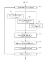
次に、図3を用いて、本発明の実施例1に係る画像符号化装置における符号化方法の流れについて説明する。
まず、ステップ301で符号化対象となる原画像を入力し、画像の内容を解析して分割方法を決定し、ブロックに分割する。画像内容の解析は、画像全体で行ってもよいし、複数フレームを組み合わせて行ってもよいし、画像を分割したスライスやタイル、ブリック、CTU等各ブロック単位で行ってもよい。ブロックの分割は、一般に一定サイズのCTUに分割した後、ツリー構造によってCUに分割される。
次に、ステップ302では、ステップ301で取得した原画像の符号化対象ブロックについてイントラ予測を行う。イントラ予測モードについては前述の通りである。各イントラ予測モードに従って複数のモードについて予測を行う。
次に、ステップ303では、ステップ301で取得した原画像の符号化対象ブロックについてインター予測を行う。インター予測モードについては前述の通りである。各インター予測モードに従って複数のモードについて予測を行う。
次に、ステップ320では、ステップ301で取得した原画像の符号化対象ブロックについて合成予測を行う。合成予測モードの詳細については後述する。
次に、ステップ304では、各モードに対して、イントラ予測、インター予測、合成予測された符号化対象ブロックの画素について残差成分を分離し、残差成分の変換処理と量子化処理、エントロピー符号化処理とを行い、符号化データを算出する。
次に、ステップ305では、各モードに対して、逆量子化、逆変換処理を行い、残差成分を予測画像と合成することにより、復号画像の作成を行う。復号画像は、イントラ予測やインター予測における予測データおよび各種符号化データとともに管理され、他の符号化対象ブロックの予測に利用される。
次に、ステップ306では、各モードを比較して、最も効率的に符号化できるモードを決定する。モードには、イントラ予測モード、インター予測モード、合成予測モード等があり、これらを総称して符号化モードと呼ぶ。モード選択方法については前述の通りである。
ステップ307では、決定された符号化モードに従い、符号化対象ブロックの符号化データを出力する。上記の各符号化対象ブロックの符号化プロセスを画像全体に対して繰り返し行い、画像の符号化が行われる。
次に、本実施例に係る合成予測モードについて説明する。なお、当該合成予測モードによる予測画像生成処理は、符号化側、復号側で同じ処理を行う。従って、本実施例に係る合成予測モードに関する以下の説明は、特に断りがない限り符号化側と復号側で同じ処理を行うものである。
本実施例に係る合成予測モードは、イントラ予測によるイントラ予測画像とインター予測によるインター予測画像とを重みづけ平均することにより、合成予測による予測画像を生成する。具体的には、インター予測画素Pinter, イントラ予測画素Pintraとして、予測画像の各予測画素Pcom(以下、合成予測画素と称する)を以下の式1により算出する。
Pcom = (w * Pintra + (4 - w) * Pinter) / 4 …式1
すなわち、式1の処理は、重みづけパラメータであるwを用いた、インター予測画素とイントラ予測画素の重みづけ平均処理である。なお、当該処理は重みづけ加算と表現してもよい。
すなわち、式1の処理は、重みづけパラメータであるwを用いた、インター予測画素とイントラ予測画素の重みづけ平均処理である。なお、当該処理は重みづけ加算と表現してもよい。
本実施例に係る合成予測モードで用いるインター予測画像は、上述のインター予測モードで用いうるすべてのインター予測による予測画像を候補としても構わない。また、上述のインター予測モードのうち、マージモードによる予測画像のみを対象としても構わない。
本実施例に係る合成予測モードで用いるイントラ予測画像は、上述のイントラ予測モードで用いうるすべてのイントラ予測による予測画像を候補としても構わない。また、上述のイントラ予測モードのうち、アングラー予測、DC予測、プラナー予測による予測画像のみを対象としても構わない。
ここで、本実施例に係る合成予測モードでは、合成予測画素の算出に用いる重みづけパラメータwを、合成予測モードで用いるイントラ予測画像を生成するイントラ予測の種類に応じて決定する。すなわち、異なるイントラ予測のそれぞれの特徴に応じて、イントラ予測画像とインター予測画像との重みづけ平均における、イントラ予測画像の重みを変更することにより、より好適な予測画像の生成を図る。
以下、本実施例に係る合成予測モードにおける重みづけパラメータwの決定処理の具体的な例を説明する。
まず、本実施例に係る合成予測モードで用いるイントラ予測画像の生成に用いる候補に含まれるイントラ予測である、アングラー予測、DC予測、プラナー予測について、図6および図7を用いて説明する。
図6に、アングラー予測の予測方向を示す。アングラー予測は予測対象画素のそれぞれについて、図示する各予測方向により指し示される隣接画素を参照して予測する予測方法である。当該予測は一方向予測であり、隣接画素値を各予測方向の反対方向にコピーする予測ということもできる。各予測方向は番号で識別可能であり、例えば、図示する予測方向2~66のように設定する。本図では、代表的な予測方向である2(左下方向)、18(左水平方向(水平方向))、34(左上方向)、50(上方向(垂直方向))、66(右上方向)を示している。本図では、説明を簡単にするために他の予測方向の表記は省略するが、予測方向2から予測方向66まで、予測方向番号が増えるごとに時計回りの回転方向に予測方向が定義されている。アングラー予測では隣接画素値に基づく一方向予測である。
よって、ストライプ柄など所定方向に絵柄が延伸する画像に対して、予測残差を小さくできる傾向がある。予測残差が小さくなるとはすなわち圧縮率が高くなることである。符号化側でアングラー予測を選択するときは、アングラー予測で予測残差が小さくなる画像を符号化するときであるが、これは所定方向に絵柄が延伸する画像である可能性が高い。すると、符号化側で符号化対象ブロックにアングラー予測を選択するときは、隣接するブロックにおいても、符号化対象ブロックと同じ予測方向または符号化対象ブロックの予測方向に近い予測方向を用いたアングラー予測を採用している可能性が高くなる。所定方向に絵柄が延伸する画像における、絵柄の延伸が継続する限り、符号化対象ブロックと同じ予測方向または符号化対象ブロックの予測方向に近い予測方向のアングラー予測で予測残差か小さくなる可能性が高いからである。これは、予測精度が高い可能性が高い、と表現することもできる。
この場合、隣接する複数のブロックで、同じ予測方向のアングラー予測または当該方向に近い予測方向のアングラー予測が繰り返し選択される可能性が高い。すなわち、アングラー予測は隣接ブロックとの予測方法の近似性が比較的高いイントラ予測であるといえる。なお、「符号化対象ブロックの予測方向に近い予測方向」とは、具体的には、予測方向の番号が符号化対象ブロックの予測方向の番号の±1の予測方向と定義してもよい。または、具体的には、予測方向の番号が符号化対象ブロックの予測方向の番号の±2の予測方向と定義してもよい。
また、図6には、さらにDC予測の番号が1と示されている。DC予測とは、周波数領域のDC成分のみに相当する予測画像を生成する予測方法である。すなわち、DC予測の予測画像内の画素値がすべて一定値である。DC予測は隣接画素値に基づかない予測方法である。しかしながら、DC予測で予測残差を小さくできる傾向がある画像は一定輝度が広く続く平面的な絵柄などである。すると、符号化側で符号化対象ブロックにDC予測を選択するときは、隣接するブロックにおいても、符号化対象ブロックと同じDC予測を採用している可能性が高くなる。一定輝度の平面的な絵柄が周囲方向に繋がっている限り、同じDC予測で予測残差か小さくなる可能性が高いからである。
これは、予測精度が高い可能性が高い、と表現することもできる。この場合、隣接する複数のブロックで、同じDC予測が繰り返し選択される可能性が高い。すなわち、DC予測は隣接画素値に基づかない予測方法であるにも関わらず、隣接ブロックとの予測方法の近似性が比較的高いイントラ予測であるといえる。
また、図6には、さらにプラナー予測の番号が0と示されている。プラナー予測の具体的な予測方法を図7に示す。プラナー予測では、符号化対象ブロックの右上隣接画素を用いて(処理710)、符号化対象ブロックの右側境界に参照画素を生成する(処理711)。次に、当該右側参照画素と、当該右側参照画素に対向する左側隣接画素とを用いた線形補間により各予測画素を生成して第1の予測画像(図7(A))を生成する(処理712)。
また、符号化対象ブロックの左下隣接画素を用いて(処理720)、符号化対象ブロックの下側境界に参照画素を生成する(処理721)。次に、当該下側参照画素と、当該下側参照画素に対向する上側隣接画素とを用いた線形補間により各予測画素を生成して第2の予測画像(図7(B))を生成する(処理722)。そして、このように生成した第1の予測画像(図7(A))と第2の予測画像(図7(B))を平均して最終予測画像を生成する。プラナー予測は、このように、線形補間で生成した第1の予測画像(図7(A))と第2の予測画像(図7(B))を平均することで非線形曲面の予測画像を生成する点で特徴のあるイントラ予測である。
プラナー予測は、隣接画素値に基づく予測である。しかしながら、プラナー予測で生成される予測画像が特徴的な非線形曲面になるため、隣接ブロックとの予測方法の近似性は決して高くない。上述のように、アングラー予測やDC予測で予測残差が小さくなる場合は、隣接ブロックと同じ予測方法が繰り返される可能性が高い。これに対して、プラナー予測の予測画像の特徴的な非線形曲面が繰り返される必要のある絵柄の画像は、多くない。
よって、プラナー予測は、隣接ブロックとの予測方法の近似性が比較的低いイントラ予測であるといえる。また、符号化側で符号化対象ブロックにプラナー予測を選択するときは、アングラー予測やDC予測では予測残差が十分に小さくならなかった画像である可能性が高い。アングラー予測やDC予測では予測残差が十分に小さくならない画像は、単純な絵柄ではない可能性が高いため、アングラー予測やDC予測で予測残差か小さくならなかった画像に対するプラナー予測による予測残差は、アングラー予測やDC予測で予測残差が小さくなるときの予測残差に比べて大きい可能性が高い。これは、予測精度が低い可能性が高い、と表現することもできる。
図6および図7を用いて説明したように、本実施例に係る合成予測モードで用いることができる、アングラー予測、DC予測、プラナー予測はそれぞれ異なる特徴を有するイントラ予測である。そこで、本実施例に係る合成予測モードでは、このようなイントラ予測の種類ごとの特徴に注目して、イントラ予測の種類に応じて式1の重みづけパラメータwの値を決定する制御を行う。図8を用いて、本実施例に係る合成予測モードにおけるw決定処理を説明する。
図8は、本実施例に係る合成予測モードにおけるw決定例を示したものである。図8には、w決定例1、w決定例2、w決定例3の3つの例を示している。それぞれ異なる決定方法の例である。それぞれの決定方法において、条件ごとに、wの値を1、2、3のいずれかから決定する。式1では、wの値が多い大きいほど、合成予測モードにおけるイントラ予測の重みづけが大きくなる。逆に、式1では、wの値が多い小さいほど、合成予測モードにおけるイントラ予測の重みづけが小さくなる。以下これらの決定例について説明する。
w決定例1は、合成予測モードで用いるイントラ予測がプラナー予測の場合w=1と決定する。合成予測モードで用いるイントラ予測がアングラー予測で予測方向が水平方向(18)または垂直方向(50)の場合はw=3と決定する。合成予測モードで用いるイントラ予測がアングラー予測で予測方向が2~17または51~66の場合はw=3と決定する。合成予測モードで用いるイントラ予測がアングラー予測で予測方向が19~49の場合はw=3と決定する。合成予測モードで用いるイントラ予測がDC予測の場合はw=3と決定する。
すなわち、w決定例1では、隣接ブロックとの予測方法の近似性が比較的低いイントラ予測であるプラナー予測は、アングラー予測およびDC予測に比べて小さいwの値を取りうるようにした決定方法である。プラナー予測の予測画像が特徴的な非線形曲面であり、予測精度が低い可能性が高いため、合成予測モードにおける最も小さい重みづけを取りうるようにした方が好適である、という表現もできる。
これに対し、w決定例1では、隣接ブロックとの予測方法の近似性が比較的高いイントラ予測であるアングラー予測は、いずれの予測方向でも、プラナー予測におけるwの値よりも大きいwの値である3を選択する。隣接ブロックとの予測方法の近似性が比較的高いイントラ予測であるアングラー予測は、プラナー予測に比べて大きいwの値を取りうるようにした決定方法である。アングラー予測の予測画像がシンプルな一方向予測面であり、予測精度が高い可能性が高いため、合成予測モードにおいて比較的大きい重みづけを取りうるようにした方が好適である、という表現もできる。
また、w決定例1では、隣接ブロックとの予測方法の近似性が比較的高いイントラ予測であるDC予測は、プラナー予測におけるwの値よりも大きいwの値である3を選択する。隣接ブロックとの予測方法の近似性が比較的高いイントラ予測であるDC予測は、プラナー予測に比べて大きいwの値を取りうるようにした決定方法である。DC予測の予測画像がシンプルな一定値平面であり、予測精度が高い可能性が高いため、合成予測モードにおいて比較的大きい重みづけを取りうるようにした方が好適である、という表現もできる。
このように、w決定例1は、イントラ予測の種類に応じて、wの値を決定する。このとき、プラナー予測が最も小さい値になりうるように設定されるものである。また、アングラー予測においては、いずれの予測方向であってもwの値が一定になるように設定されている。すなわちw決定例1では、アングラー予測の予測方向に応じてwの値が変化することはない。
次に、w決定例2では、合成予測モードで用いるイントラ予測がプラナー予測の場合w=1と決定する。合成予測モードで用いるイントラ予測がアングラー予測で予測方向が水平方向(18)または垂直方向(50)の場合はw=2と決定する。合成予測モードで用いるイントラ予測がアングラー予測で予測方向が2~17または51~66の場合はw=3と決定する。合成予測モードで用いるイントラ予測がアングラー予測で予測方向が19~49の場合はw=3と決定する。合成予測モードで用いるイントラ予測がDC予測の場合はw=3と決定する。
すなわち、w決定例2では、w決定例1と同様に、隣接ブロックとの予測方法の近似性が比較的低いイントラ予測であるプラナー予測は、アングラー予測およびDC予測に比べて小さいwの値を取りうるようにした決定方法である。理由はw決定例1と同様である。w決定例2では、隣接ブロックとの予測方法の近似性が比較的高いイントラ予測であるアングラー予測は、いずれの予測方向でも、プラナー予測におけるwの値よりも大きいwの値である2または3を選択する。隣接ブロックとの予測方法の近似性が比較的高いイントラ予測であるアングラー予測は、プラナー予測に比べて大きいwの値を取りうるようにした決定方法である。
アングラー予測の予測画像がシンプルな一方向予測面であり、予測精度が高い可能性が高いため、合成予測モードにおいて比較的大きい重みづけを取りうるようにした方が好適である、という表現もできる。ただし、w決定例2では、w決定例1と異なり、同じアングラー予測であっても予測方向に応じて、wの値を変化させる。
具体的には、予測方向が水平方向(18)または垂直方向(50)の場合はw=2とし、アングラー予測における他の予測方向のw=3に比べて低い重みづけに設定している。これは、水平方向(18)の予測方向は参照画素が左隣接ブロックの画素のみであり、隣接ブロックとの予測方法の近似性が左隣接ブロックに限定される可能性が高く、総合的な隣接ブロックとの予測方法の近似性が、他の予測方向よりも低いと考えられるためである。
また、同様に、これは、垂直方向(50)の予測方向は参照画素が上隣接ブロックの画素のみであり、隣接ブロックとの予測方法の近似性が上隣接ブロックに限定される可能性が高く、総合的な隣接ブロックとの予測方法の近似性が、他の予測方向よりも低いと考えられるためである。また、w決定例2では、w決定例1と同様に、隣接ブロックとの予測方法の近似性が比較的高いイントラ予測であるDC予測は、プラナー予測におけるwの値よりも大きいwの値である3を選択する。理由はw決定例1と同様である。
このように、w決定例2は、イントラ予測の種類に応じて、wの値を決定する。また、イントラ予測がアングラー予測である場合は、予測方向も考慮してwの値を決定する。また、プラナー予測が最も小さい値になりうるように設定されるものである。
w決定例3は、w決定例2に対して、合成予測モードで用いるイントラ予測がアングラー予測で予測方向2~17または51~66の場合はw=2と決定する点で相違し、その他の点は共通である。アングラー予測で予測方向2~17または51~66の場合は、予測方向の角度が、完全な水平方向または完全な垂直方向ではないため、上隣接ブロックと左側隣接ブロックのいずれにも予測方法の近似性が認められる。
しかしながら、参照画素に含まれている画素は、上隣接ブロックの画素または左側隣接ブロックの画素のいずれか一方である。予測方向2~17または51~66の場合は、上隣接ブロックの画素および左側隣接ブロックの画素の両者を参照画素に含む予測方向19~49の場合に比べて、総合的な隣接ブロックとの予測方法の近似性が低い可能性がある。そこで、w決定例3では、予測方向2~17または51~66の場合は、w=2と決定し、予測方向19~49の場合よりも重みづけを小さくしている。
以上説明した図8の合成予測モードにおけるwの決定例によれば、合成予測モードに用いるイントラ予測の種類ごとの特徴に応じて、イントラ予測画像とインター予測画像の合成におけるイントラ予測画像の重みづけをより好適に決定することが可能となる。
以上説明したように、本願の一実施例における符号化処理が行われる。
以上説明した実施例1に係る画像符号化装置および画像符号化方法によれば、より好適な合成予測モードを実現することができる。
また、実施例1に係る画像符号化装置および画像符号化方法は、これらを用いた記録装置、携帯電話、デジタルカメラ等に適用することが可能である。
以上説明した本発明の実施例1に係る画像符号化装置および画像符号化方法によれば、符号化データの符号量を低減し、当該符号化データを復号した場合の復号画像の画質の劣化を防ぐことが可能となる。すなわち、高い圧縮率とより良い画質とを実現することができる。
すなわち、本発明の実施例1に係る画像符号化装置および画像符号化方法によれば、より好適な画像符号化技術を提供することができる。
(実施例2)
次に、図2に本発明の実施例2に係る画像復号装置のブロック図の一例を示す。
次に、図2に本発明の実施例2に係る画像復号装置のブロック図の一例を示す。
画像復号装置は例えば、ストリーム解析部201、ブロック管理部202、モード判定部203、イントラ予測部204、インター予測部205、合成予測部220、係数解析部206、逆量子化・逆変換部207、画像合成・フィルタ部208、復号画像管理部209、画像出力部210を備える。
以下に画像復号装置の各構成要素の動作を詳細に説明する。
なお、画像復号装置の各構成要素の動作は、例えば、以下の記載の通り各構成要素の自律的な動作としてもよい。また、例えば制御部や記憶部が記憶するソフトウェアと協働することにより実現しても構わない。
まず、ストリーム解析部201が、入力された符号化ストリームを解析する。ここで、ストリーム解析部201は、パケットからのデータ抽出処理や各種ヘッダ、フラグの情報取得処理も行う。
また、このとき、ストリーム解析部201に入力される符号化ストリームは、例えば、実施例1に係る画像符号化装置および画像符号化方法により生成された符号化ストリームである。その生成方法は、実施例1に示した通りであるので説明を省略する。実施例3に示すデータ記録媒体から読み出した符号化ストリームであってもよい。その記録方法は後述する。
次に、ブロック管理部202は、ストリーム解析部201によって解析されたブロック分割の情報に従ってブロックの処理を管理する。一般に符号化された画像はブロックに分割され、それぞれの符号化対象ブロックはツリー構造等によって管理されている。ブロックの処理順序はラスタースキャン順に行われることが多いが、ジグザグスキャンなど任意の決められた順序によって処理すればよい。ブロックの分割方法は実施例1で述べた通りである。
次に、モード判定部203は、各符号化対象ブロックについて、フラグ等によって指定された符号化モードの判別を行う。以下の復号処理は、当該判別結果の符号化モードに対応する処理が行われる。以下にそれぞれの符号化モードについての処理を説明する。
まず、符号化モードがイントラ符号化である場合には、イントラ予測部204がイントラ予測による予測画像の生成を行う。イントラ予測モードについては実施例1で述べた通りである。予測による予測画像の生成処理は原則として符号化側と復号側で同じ処理である。
符号化モードがインター予測による符号化である場合には、インター予測部205がインター予測による予測画像の生成を行う。インター予測モードについては実施例1で述べた通りである。予測による予測画像の生成処理は原則として符号化側と復号側で同じ処理である。
符号化モードが合成予測による符号化である場合には、合成予測部220が合成予測による予測画像の生成を行う。合成予測モードについては実施例1で述べた通りである。予測による予測画像の生成処理は原則として符号化側と復号側で同じ処理である。
一方、係数解析部206は、入力符号化ストリームに含まれる各符号化対象ブロックの符号化データを解析し、エントロピー符号化されたデータの復号を行い、残差成分の係数列を含む符号化データを出力する。このとき、モード判定部203の判別結果の符号化モードに対応する処理が行われる。
逆量子化・逆変換部207は残差成分の係数列を含む符号化データに逆量子化処理と逆変換を行い、残差成分を復元する。逆量子化、逆変換の方法は前述の通りである。逆量子化や逆変換はモードの指定によりスキップされてもよい。
上記のようにして復元された残差成分は、画像合成・フィルタ部208によってイントラ予測部204、インター予測部205、または合成予測部220から出力される予測画像と合成され、さらにループフィルタ等の処理が行われ復号画像として出力される。
復号画像管理部209は、復号画像を保持し、イントラ予測、インター予測、または合成予測のために参照される画像、モードの情報等を管理する。
最後に復号された画像が画像出力部210によって出力され、画像の復号が行われる。
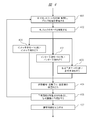
次に、図4を用いて、本発明の実施例2に係る画像復号装置における画像復号方法の流れについて説明する。
まず、ステップ401で、復号対象となる符号化ストリームを取得し、データの解析を行う。また解析されたブロック分割の情報に従ってブロックの処理を管理する。ブロックの分割方法は実施例1で述べた通りである。
次に、ステップ402では、ステップ401において解析した符号化モードの情報を用いて、当該符号化データに含まれる1つの符号化単位(ブロック単位や画素単位など)についての符号化モードを判定する。ここでイントラ符号化モードである場合にはステップ403に進み、インター符号化モードである場合にはステップ404に進み、合成符号化モードである場合にはステップ420に進む。
ステップ403では、符号化モードによって指定された方法に従ってイントラ予測により予測画像の生成を行う。イントラ予測モードについては実施例1で述べた通りである。
ステップ404では、符号化モードによって指定された方法に従ってインター予測により予測画像の生成を行う。インター予測モードについては実施例1で述べた通りである。
ステップ420では、符号化モードによって指定された方法に従って合成予測により予測画像の生成を行う。合成予測モードについては実施例1で述べた通りである。
ステップ405では、符号化モードによって指定された方法に従って各符号化対象ブロックの符号化データを解析し、エントロピー符号化されたデータの復号を行い、残差成分の係数列を含む符号化データを出力する。さらに、残差成分の係数列を含む符号化データに逆量子化処理と逆変換を行い、残差成分を復元する。逆量子化、逆変換の方法は前述の通りである。逆量子化や逆変換はモードの指定によりスキップされてもよい。
ステップ406では、各符号化対象ブロックに対して、イントラ予測、インター予測または、合成予測等によって生成された予測画像と、復元された残差成分を合成し、さらにループフィルタ等の処理を行うことによって復号画像を作成する。上記の符号化対象ブロック単位で行われる復号のプロセスを画像全体に対して行うことによって、復号画像が作成される。
ステップ407では生成された復号画像を出力、表示する。
本実施例に係る復号側の合成予測モードにおける処理は、実施例1において、式1、図6、図7、および図8を用いて説明した合成予測モードにおける処理と実質的に同一であるため、繰り返しの説明を省略する。なお、実施例1の合成予測モードの説明における「符号化対象ブロック」という表現は、復号側の合成予測モードの処理においては、「復号対象ブロック」と読み替えればよい。
本実施例に係る復号側の合成予測モードでは、上述の通り、式1を用いたインター予測画素とイントラ予測画素の重みづけ平均処理を行う。また、本実施例に係る復号側の合成予測モードでは、上述の通り、重みづけパラメータwを、図8に示すような決定処理により決定する。これにより、合成予測モードに用いるイントラ予測の種類ごとの特徴に応じて、イントラ予測画像とインター予測画像の合成におけるイントラ予測画像の重みづけをより好適に決定することが可能となる。
なお、本実施例においても、例に示す以外にも、符号化モードで用いるブロックのサイズなどをパラメータとして、各符号化モードを細分化して規定した符号化ストリームを、復号対象ストリームとしてもよい。
以上説明したように、本願の一実施例における復号処理が行われる。
また、実施例2に係る画像復号装置および画像復号方法は、これらを用いた再生装置、携帯電話、デジタルカメラ等に適用することが可能である。
以上説明した本発明の実施例2に係る画像復号装置および画像復号方法によれば、符号量の少ない符号化データをより高画質に復号することが可能となる。
すなわち、本発明の実施例2に係る画像復号装置および画像復号方法によれば、より好適な画像復号技術を提供することができる。
(実施例3)
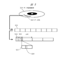
次に、図5に本発明の実施例3に係るデータ記録媒体の一例を示す。
次に、図5に本発明の実施例3に係るデータ記録媒体の一例を示す。
本発明の本実施例に係る符号化ストリームは、実施例1に係る実施例1に係る画像符号化装置または画像符号化方法により生成された符号化ストリームである。その生成方法は、実施例1に示した通りであるので、説明を省略する。
ここで、本実施例に係る符号化ストリームは、例えば、データ記録媒体501上にデータ列502として記録される。データ列502は、例えば、所定の文法に従う符号化ストリームとして記録されている。
まず、符号化ストリームはNAL(Network Abstraction Layer)ユニット503と呼ばれる一定サイズの単位に区切られたビット列として取り出される。NALユニットのビット列は、可変長符号等の一定のルールに従って読み出され、RBSP(Raw Byte Sequence Payload)として変換される。RBSPのデータは、シーケンスパラメータセット504、ピクチャパラメータセット505、デコーディングパラメータセット、ビデオパラメータセット等の情報や、スライスデータ506から構成される。
各スライスの内部には、例えば、それぞれのブロックに関する情報507が含まれている。ブロックに関する情報の内部には、例えば、ブロックごとにそれぞれの符号化モードを記録する領域があり、これを符号化モードフラグ508とする。
以上説明した本発明の実施例3に係るデータ記録媒体によれば、符号量を低減し、画質の劣化を防ぐことができる。すなわち、圧縮率が高く、画質のより良い符号化ストリームを記録するデータ記録媒体を実現することができる。
なお、以降に説明する各実施例における画像符号化装置または画像符号化方法により生成された符号化ストリームも、本実施例で上述した構成により本実施例に係るデータ記録媒体に記録することができる。
(実施例4)
次に、本発明の実施例4について図面を参照して説明する。
次に、本発明の実施例4について図面を参照して説明する。
本発明の実施例4は、実施例1に係る画像符号化装置および画像符号化方法において、合成予測の処理における重みづけパラメータwの決定処理を変更したものである。
具体的には、重みづけパラメータwの決定処理を図8に示す重みづけパラメータwの決定処理から図9に示す重みづけパラメータwの決定処理に変更する。実施例4に係る画像符号化装置および画像符号化方法は、図9に示す重みづけパラメータwの決定処理以外のその他の構成、動作、処理はいずれも実施例1に係る画像符号化装置および画像符号化方法と同様である。よって、これら実施例1に係る画像符号化装置および画像符号化方法と同様の点は繰り返しの説明を省略する。
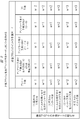
図9に本発明の実施例4に係る画像符号化装置および画像符号化方法における合成予測の処理における重みづけパラメータwの決定処理の一例を示す。なお、復号側でも同様の重みづけパラメータwの決定処理を行うので、予測対象ブロックは「符号化(復号)対象ブロック」という表現で説明する。
図9の例では、図8の例と異なり、重みづけパラメータwの決定する処理を行うにあたり、符号化(復号)対象ブロックのイントラ予測モードだけではなく、複数の隣接ブロックの予測モードの組み合わせも考慮する。ここで、本実施例では、複数の隣接ブロックの一例として、符号化(復号)対象ブロックの直上に隣接するブロックと符号化(復号)対象ブロックの直左に隣接するブロックの2つの隣接ブロックの予測モードの組み合わせを考慮する。
すなわち、図8の例では、符号化(復号)対象ブロックのイントラ予測モードのみに応じて、重みづけパラメータwを決定していたが、図9の例は、符号化(復号)対象ブロックのイントラ予測モードが同じであっても、複数の隣接ブロックの予測モードの組み合わせが異なれば重みづけパラメータwを変化させる。
実施例1において、符号化(復号)対象ブロックのイントラ予測モードの種類によって、隣接ブロックとの予測方法の近似性がそれぞれ異なることを既に説明した。具体的には、プラナー予測、アングラー予測で予測方向18または50の場合、アングラー予測で予測方向2~17または51~66の場合、アングラー予測で予測方向2~17または51~66の場合、アングラー予測で予測方向が19~49の場合、DC予測のそれぞれについて、隣接ブロックとの予測方法の近似性の特徴を説明した。
図9では、これらのイントラ予測モードの種類の特徴ごとに複数の隣接ブロックの予測モードの組み合わせに応じて重みづけパラメータwを決定する。
複数の隣接ブロックの予測モードの組み合わせの具体的条件としては、(1)符号化(復号)対象ブロックの直上に隣接するブロックと符号化(復号)対象ブロックの直左に隣接するブロックの2つの隣接ブロックのいずれもが利用不可の場合、(2)符号化(復号)対象ブロックの直上に隣接するブロックと符号化(復号)対象ブロックの直左に隣接するブロックの2つの隣接ブロックの一方が利用不可で他方がインター予測の場合、(3)符号化(復号)対象ブロックの直上に隣接するブロックと符号化(復号)対象ブロックの直左に隣接するブロックの2つの隣接ブロックの両方ともインター予測の場合、(4)符号化(復号)対象ブロックの直上に隣接するブロックと符号化(復号)対象ブロックの直左に隣接するブロックの2つの隣接ブロックの一方が利用不可で他方がイントラ予測の場合、(5)符号化(復号)対象ブロックの直上に隣接するブロックと符号化(復号)対象ブロックの直左に隣接するブロックの2つの隣接ブロックの一方がインター予測で他方がイントラ予測の場合、(6)符号化(復号)対象ブロックの直上に隣接するブロックと符号化(復号)対象ブロックの直左に隣接するブロックの2つの隣接ブロックの両方ともイントラ予測の場合の(1)~(6)の条件を考慮する。
具体的には上記(1)~(6)の条件ごとに以下の通りに決定する。
まず、符号化(復号)対象ブロックのイントラ予測モードがプラナー予測である場合は、図9に示すようにwを決定すればよい。具体的には、条件(1)~(3)ではw=1とし、条件(4)~(6)ではw=2とする。実施例1で説明した通りプラナー予測は隣接ブロックとの予測方法の近似性が比較的低いイントラ予測である。
しかしながら、隣接ブロックに利用可能なイントラ予測ブロックが存在する場合には、符号化(復号)対象ブロックと同様のプラナー予測の可能性もあるので、若干ではあるが隣接ブロックとの予測方法の近似性が改善する。従って、条件(4)~(6)について、条件(1)~(3)よりも重みづけを大きくするのが好適である。なお、変形例として、条件(1)~(5)ではw=1とし、条件(6)のみw=2としてもよい。プラナー予測はその処理の中で対象ブロックの上側隣接画素、左側隣接画素の両者を用いるので、複数の隣接ブロックの予測モードの両者がイントラ予測の場合のみ予測方法の近似性が改善するという考え方を用いた変形例である。
次に、符号化(復号)対象ブロックのイントラ予測モードがアングラー予測で予測方向18または50の場合は、図9に示すようにwを決定すればよい。具体的には、条件(1)~(3)ではw=1とし、条件(4)~(6)ではw=2とする。イントラ予測モードがアングラー予測で予測方向18または50の場合は、水平方向または垂直方向のいずれか一方の隣接ブロックと予測方法の近似性を有するイントラ予測である。
よって、利用可能なイントラ予測ブロックが存在する条件(4)~(6)について、条件(1)~(3)よりも重みづけを大きくするのが好適である。ただし、隣接ブロックと予測方法の近似性の効果が水平方向または垂直方向のいずれか一方に限定される。よって、複数の隣接ブロックの両方ともが利用可能なイントラ予測である条件(6)であっても、複数の隣接ブロックのうち一方のみが利用可能なイントラ予測である条件(4)(5)と比べても隣接ブロックと予測方法の近似性の効果は変わらない。従って、本図の例では、条件(6)でもw=2とした。
次に、符号化(復号)対象ブロックのイントラ予測モードがアングラー予測で予測方向2~17または51~66の場合およびアングラー予測で予測方向2~17または51~66の場合は、図9に示すようにwを決定すればよい。具体的には、条件(1)~(3)ではw=1とし、条件(4)、(5)ではw=2とし、(6)ではw=3とする。イントラ予測モードがアングラー予測で予測方向2~17または51~66の場合およびアングラー予測で予測方向2~17または51~66の場合は、予測方向が斜め方向であるため、上側に隣接するブロックと左側に隣接するブロックの両者と予測方法の近似性を有するイントラ予測である。従って、隣接ブロックに利用可能なイントラ予測ブロックが増えれば増えるほど、隣接ブロックと予測方法の近似性が高まる傾向になる。よって、上述のように隣接ブロックに利用可能なイントラ予測ブロックが増えるほど、重みづけパラメータwの値を大きく設定するのが好適である。
次に、符号化(復号)対象ブロックのイントラ予測モードがDC予測の場合は、図9に示すようにwを決定すればよい。具体的には、条件(1)~(3)ではw=2とし、条件(4)~(6)では、w=3とする。実施例1で説明した通り、符号化側の処理においてDC予測を選択するときは、符号化対象画像が、一定輝度が広く続く平面的な絵柄である可能性が高い。隣接ブロックに利用可能なイントラ予測ブロックが含まれているときは特にこの可能性が高いので、w=3とするのが好適である。ただし、本図の例では、隣接ブロックに利用可能なイントラ予測ブロックが含まれない場合は、符号化対象画像が、一定輝度が広く続く平面的な絵柄である可能性が若干下がるため、w=2としている。
以上説明した図9の重みづけパラメータwの決定処理によれば、合成予測の処理における数式1の重みづけパラメータwの決定において、符号化(復号)対象ブロックのイントラ予測モードだけではなく、複数の隣接ブロックの予測モードの組み合わせも考慮することでより好適に重みづけパラメータwを決定することができる。
また、複数の隣接ブロックの予測モードの組み合わせを条件とすることで、新たなフラグの伝送無しに好適な条件設定を行うことができる。
なお、図9の例では、符号化(復号)対象ブロックの予測モードがいずれの予測モードであっても、条件(1)よりも(6)において重みづけwを大きくする。符号化(復号)対象ブロックの予測モードがいずれの予測モードであっても、隣接ブロックに利用可能なイントラ予測ブロックが増えれば、少なからず隣接ブロックと予測方法の近似性が高まる傾向になるためである。
また、図9の例では、合成予測で用いるイントラ予測に、プラナー予測もDC予測も指定されていない場合、複数の隣接ブロックに利用可能なイントラ予測ブロックがない場合よりも、複数の隣接ブロックに利用可能なイントラ予測ブロックがある場合において、重みづけwを大きくする。
なお、図9の変形例として、図10のように、DC予測の条件(4)、(5)は、w=2としてもよい。図10の例は、DC予測でw=3となるのを条件(6)のみとした。複数の隣接ブロックの両方ともが利用可能なイントラ予測である条件(6)のみ、符号化対象画像が、一定輝度が広く続く平面的な絵柄である可能性が高いと考える例である。図10の例はDC予測の条件(4)、(5)以外は、図9と同じであるため、繰り返しの説明は省略する。
以上説明した、本発明の実施例4に係る画像符号化装置および画像符号化方法によれば、より好適に画像を符号化することができる。
(実施例5)
次に、本発明の実施例5について説明する。
次に、本発明の実施例5について説明する。
本発明の実施例5は、実施例2に係る画像復号装置および画像復号方法において、合成予測の処理における重みづけパラメータwの決定処理を変更したものである。
具体的には、重みづけパラメータwの決定処理を図8に示す重みづけパラメータwの決定処理から図9または図10に示す重みづけパラメータwの決定処理に変更する。実施例5に係る画像復号装置および画像復号方法は、図9または図10に示す重みづけパラメータwの決定処理を用いるものであるが、図9または図10に示す重みづけパラメータwの決定処理以外のその他の構成、動作、処理はいずれも実施例2に係る画像復号装置および画像復号方法と同様である。よって、これら実施例2に係る画像復号装置および画像復号方法と同様の点は繰り返しの説明を省略する。
また、図9または図10の重みづけパラメータwの決定処理の詳細については、実施例4で説明した通りであるので、繰り返しの説明を省略する。
以上説明した、本発明の実施例5に係る画像復号装置および画像復号方法では、図9または図10に示すように合成予測の処理における数式1の重みづけパラメータwの決定において、符号化(復号)対象ブロックのイントラ予測モードだけではなく、複数の隣接ブロックの予測モードの組み合わせも考慮することでより好適に重みづけパラメータwを決定することができる。
以上説明した、本発明の実施例5に係る画像復号装置および画像復号方法によれば、より好適に画像を復号することができる。
なお、以上説明した各図、各方法等の実施例のいずれを組み合わせても、本発明の一実施の形態となりうる。
以上説明した本発明の各実施例によれば、符号量を低減し、画質の劣化を防ぐことができる。すなわち、高い圧縮率とより良い画質とを実現することができる。
101…画像入力部、102…ブロック分割部、103…モード管理部、104…イントラ予測部、105…インター予測部、106…ブロック処理部、107…変換・量子化部、108…逆量子化・逆変換部、109…画像合成・フィルタ部、110…復号画像管理部、111…エントロピー符号化部、112…データ出力部、201…ストリーム解析部、202…ブロック管理部、203…モード判定部、204…イントラ予測部、205…インター予測部、206…係数解析部、207…逆量子化・逆変換部、208…画像合成・フィルタ部、209…復号画像管理部、210…画像出力部、120…合成予測部、220…合成予測部。
Claims (4)
- 画像を符号化する画像符号化方法であって、
符号化対象ブロックについてインター予測の予測画像とイントラ予測の予測画像とを合成する合成処理を行って合成予測の予測画像を生成する予測画像生成ステップと、
前記予測画像生成ステップで生成した予測画像と前記符号化対象ブロックの画像の画素値との差分を符号化する符号化ステップと、を備え、
前記合成処理では、前記インター予測の予測画像と前記イントラ予測の予測画像とに重みづけ処理を行うものであり、前記重みづけ処理における前記イントラ予測の予測画像の重みづけパラメータを前記符号化対象ブロックの前記イントラ予測の種類および前記符号化対象ブロックに隣接する複数の隣接ブロックの予測モードの組み合わせに応じて決定するものであり、前記符号化対象ブロックの前記イントラ予測の種類にはプラナー予測とDC予測が含まれる、画像符号化方法。 - 画像を符号化する画像符号化方法であって、
符号化対象ブロックについてインター予測の予測画像とイントラ予測の予測画像とを合成する合成処理を行って合成予測の予測画像を生成する予測画像生成ステップと、
前記予測画像生成ステップで生成した予測画像と前記符号化対象ブロックの画像の画素値との差分を符号化する符号化ステップと、を備え、
前記合成処理では、前記インター予測の予測画像と前記イントラ予測の予測画像とに重みづけ処理を行うものであり、前記符号化対象ブロックの前記合成予測で用いるイントラ予測に、プラナー予測もDC予測も指定されていない場合、前記符号化対象ブロックの直左および直上に隣接する複数の隣接ブロックに利用可能なイントラ予測ブロックがない場合よりも、前記符号化対象ブロックの前記複数の隣接ブロックに利用可能なイントラ予測ブロックがある場合において、合成予測における前記イントラ予測の予測画像の重みづけを大きくする、画像符号化方法。 - 画像を符号化した符号化ストリームを復号する画像復号方法であって、
復号対象ブロックについてインター予測の予測画像とイントラ予測の予測画像とを合成する合成処理を行って合成予測の予測画像を生成する予測画像生成ステップと、
前記予測画像生成ステップで生成した予測画像と前記復号対象ブロックの差分画像とに基づいて復号画像を生成する復号画像生成ステップと、を備え、
前記合成処理では、前記インター予測の予測画像と前記イントラ予測の予測画像とに重みづけ処理を行うものであり、前記重みづけ処理における前記イントラ予測の予測画像の重みづけパラメータを前記復号対象ブロックの前記イントラ予測の種類および前記復号対象ブロックに隣接する複数の隣接ブロックの予測モードの組み合わせに応じて決定するものであり、前記符号化対象ブロックの前記イントラ予測の種類にはプラナー予測とDC予測が含まれる、画像復号方法。 - 画像を符号化した符号化ストリームを復号する画像復号方法であって、
復号対象ブロックについてインター予測の予測画像とイントラ予測の予測画像とを合成する合成処理を行って合成予測の予測画像を生成する予測画像生成ステップと、
前記予測画像生成ステップで生成した予測画像と前記復号対象ブロックの差分画像とに基づいて復号画像を生成する復号画像生成ステップと、を備え、
前記合成処理では、前記インター予測の予測画像と前記イントラ予測の予測画像とに重みづけ処理を行うものであり、前記復号対象ブロックの前記合成予測で用いるイントラ予測に、プラナー予測もDC予測も指定されていない場合、前記復号対象ブロックの直左および直上に隣接する複数の隣接ブロックに利用可能なイントラ予測ブロックがない場合よりも、前記復号対象ブロックの前記複数の隣接ブロックに利用可能なイントラ予測ブロックがある場合において、合成予測における前記イントラ予測の予測画像の重みづけを大きくする、画像復号方法。
Priority Applications (1)
| Application Number | Priority Date | Filing Date | Title |
|---|---|---|---|
| CN202080086924.1A CN114788270A (zh) | 2019-12-17 | 2020-12-11 | 图像编码方法和图像解码方法 |
Applications Claiming Priority (2)
| Application Number | Priority Date | Filing Date | Title |
|---|---|---|---|
| JP2019-226898 | 2019-12-17 | ||
| JP2019226898A JP2021097309A (ja) | 2019-12-17 | 2019-12-17 | 画像符号化方法および画像復号方法 |
Publications (1)
| Publication Number | Publication Date |
|---|---|
| WO2021125083A1 true WO2021125083A1 (ja) | 2021-06-24 |
Family
ID=76431729
Family Applications (1)
| Application Number | Title | Priority Date | Filing Date |
|---|---|---|---|
| PCT/JP2020/046286 Ceased WO2021125083A1 (ja) | 2019-12-17 | 2020-12-11 | 画像符号化方法および画像復号方法 |
Country Status (3)
| Country | Link |
|---|---|
| JP (1) | JP2021097309A (ja) |
| CN (1) | CN114788270A (ja) |
| WO (1) | WO2021125083A1 (ja) |
-
2019
- 2019-12-17 JP JP2019226898A patent/JP2021097309A/ja active Pending
-
2020
- 2020-12-11 WO PCT/JP2020/046286 patent/WO2021125083A1/ja not_active Ceased
- 2020-12-11 CN CN202080086924.1A patent/CN114788270A/zh active Pending
Non-Patent Citations (2)
| Title |
|---|
| CHEN, JIANLE ET AL.: "Algorithm description for Versatile Video Coding and Test Model 6 (VTM 6)", JOINT VIDEO EXPERTS TEAM, no. JVET-O2002 v2, 10 September 2019 (2019-09-10), pages 52 - 53, XP030208573 * |
| M.-S. CHIANG, C.-W. HSU, Y.-W. HUANG, S.-M. LEI (MEDIATEK): "CE10.1.1: Multi-hypothesis prediction for improving AMVP mode, skip or merge mode, and intra mode", 12. JVET MEETING; 20181003 - 20181012; MACAO; (THE JOINT VIDEO EXPLORATION TEAM OF ISO/IEC JTC1/SC29/WG11 AND ITU-T SG.16 ), no. JVET-L0100 v3, 8 October 2018 (2018-10-08), XP030251646 * |
Also Published As
| Publication number | Publication date |
|---|---|
| JP2021097309A (ja) | 2021-06-24 |
| CN114788270A (zh) | 2022-07-22 |
Similar Documents
| Publication | Publication Date | Title |
|---|---|---|
| US12610040B2 (en) | Image encoding method and image decoding method | |
| US20250392705A1 (en) | Image encoding method combining prediction modes of adjacent blocks and image decoding method | |
| US20250287037A1 (en) | Image encoding method and image decoding method | |
| WO2021131796A1 (ja) | 画像符号化方法および画像復号方法 | |
| WO2021125082A1 (ja) | 画像符号化方法および画像復号方法 | |
| US20220345705A1 (en) | Methods and apparatus of video coding in 4:4:4 chroma format | |
| WO2021125084A1 (ja) | 画像符号化方法および画像復号方法 | |
| WO2021125085A1 (ja) | 画像符号化方法および画像復号方法 | |
| WO2021065656A1 (ja) | 画像符号化方法、画像符号化装置、画像復号方法および画像復号装置 | |
| WO2021125086A1 (ja) | 画像符号化方法および画像復号方法 | |
| WO2021060345A1 (ja) | 画像符号化方法および画像復号方法 | |
| JP2021097309A (ja) | 画像符号化方法および画像復号方法 | |
| US20260143141A1 (en) | Image encoding method and image decoding method | |
| US20260143142A1 (en) | Image encoding method and image decoding method | |
| US20260143162A1 (en) | Image encoding method and image decoding method | |
| WO2021065655A1 (ja) | 画像符号化方法、画像符号化装置、画像復号方法および画像復号装置 |
Legal Events
| Date | Code | Title | Description |
|---|---|---|---|
| 121 | Ep: the epo has been informed by wipo that ep was designated in this application |
Ref document number: 20904031 Country of ref document: EP Kind code of ref document: A1 |
|
| NENP | Non-entry into the national phase |
Ref country code: DE |
|
| 122 | Ep: pct application non-entry in european phase |
Ref document number: 20904031 Country of ref document: EP Kind code of ref document: A1 |