WO2021124753A1 - 手書き入力装置 - Google Patents
手書き入力装置 Download PDFInfo
- Publication number
- WO2021124753A1 WO2021124753A1 PCT/JP2020/042543 JP2020042543W WO2021124753A1 WO 2021124753 A1 WO2021124753 A1 WO 2021124753A1 JP 2020042543 W JP2020042543 W JP 2020042543W WO 2021124753 A1 WO2021124753 A1 WO 2021124753A1
- Authority
- WO
- WIPO (PCT)
- Prior art keywords
- handwriting input
- input device
- electronic data
- memory
- display surface
- Prior art date
- Legal status (The legal status is an assumption and is not a legal conclusion. Google has not performed a legal analysis and makes no representation as to the accuracy of the status listed.)
- Ceased
Links
Images


Classifications
-
- G—PHYSICS
- G06—COMPUTING OR CALCULATING; COUNTING
- G06F—ELECTRIC DIGITAL DATA PROCESSING
- G06F3/00—Input arrangements for transferring data to be processed into a form capable of being handled by the computer; Output arrangements for transferring data from processing unit to output unit, e.g. interface arrangements
- G06F3/01—Input arrangements or combined input and output arrangements for interaction between user and computer
- G06F3/03—Arrangements for converting the position or the displacement of a member into a coded form
- G06F3/033—Pointing devices displaced or positioned by the user, e.g. mice, trackballs, pens or joysticks; Accessories therefor
- G06F3/0354—Pointing devices displaced or positioned by the user, e.g. mice, trackballs, pens or joysticks; Accessories therefor with detection of two-dimensional [2D] relative movements between the device, or an operating part thereof, and a plane or surface, e.g. 2D mice, trackballs, pens or pucks
- G06F3/03545—Pens or stylus
-
- G—PHYSICS
- G06—COMPUTING OR CALCULATING; COUNTING
- G06F—ELECTRIC DIGITAL DATA PROCESSING
- G06F1/00—Details not covered by groups G06F3/00 - G06F13/00 and G06F21/00
- G06F1/26—Power supply means, e.g. regulation thereof
- G06F1/32—Means for saving power
- G06F1/3203—Power management, i.e. event-based initiation of a power-saving mode
- G06F1/3206—Monitoring of events, devices or parameters that trigger a change in power modality
- G06F1/3209—Monitoring remote activity, e.g. over telephone lines or network connections
-
- G—PHYSICS
- G06—COMPUTING OR CALCULATING; COUNTING
- G06F—ELECTRIC DIGITAL DATA PROCESSING
- G06F1/00—Details not covered by groups G06F3/00 - G06F13/00 and G06F21/00
- G06F1/26—Power supply means, e.g. regulation thereof
- G06F1/32—Means for saving power
- G06F1/3203—Power management, i.e. event-based initiation of a power-saving mode
- G06F1/3206—Monitoring of events, devices or parameters that trigger a change in power modality
- G06F1/3215—Monitoring of peripheral devices
- G06F1/3218—Monitoring of peripheral devices of display devices
-
- G—PHYSICS
- G06—COMPUTING OR CALCULATING; COUNTING
- G06F—ELECTRIC DIGITAL DATA PROCESSING
- G06F1/00—Details not covered by groups G06F3/00 - G06F13/00 and G06F21/00
- G06F1/26—Power supply means, e.g. regulation thereof
- G06F1/32—Means for saving power
- G06F1/3203—Power management, i.e. event-based initiation of a power-saving mode
- G06F1/3206—Monitoring of events, devices or parameters that trigger a change in power modality
- G06F1/3215—Monitoring of peripheral devices
- G06F1/3225—Monitoring of peripheral devices of memory devices
-
- G—PHYSICS
- G06—COMPUTING OR CALCULATING; COUNTING
- G06F—ELECTRIC DIGITAL DATA PROCESSING
- G06F1/00—Details not covered by groups G06F3/00 - G06F13/00 and G06F21/00
- G06F1/26—Power supply means, e.g. regulation thereof
- G06F1/32—Means for saving power
- G06F1/3203—Power management, i.e. event-based initiation of a power-saving mode
- G06F1/3234—Power saving characterised by the action undertaken
- G06F1/325—Power saving in peripheral device
- G06F1/3262—Power saving in digitizer or tablet
-
- G—PHYSICS
- G06—COMPUTING OR CALCULATING; COUNTING
- G06F—ELECTRIC DIGITAL DATA PROCESSING
- G06F1/00—Details not covered by groups G06F3/00 - G06F13/00 and G06F21/00
- G06F1/26—Power supply means, e.g. regulation thereof
- G06F1/32—Means for saving power
- G06F1/3203—Power management, i.e. event-based initiation of a power-saving mode
- G06F1/3234—Power saving characterised by the action undertaken
- G06F1/325—Power saving in peripheral device
- G06F1/3278—Power saving in modem or I/O interface
-
- G—PHYSICS
- G06—COMPUTING OR CALCULATING; COUNTING
- G06F—ELECTRIC DIGITAL DATA PROCESSING
- G06F1/00—Details not covered by groups G06F3/00 - G06F13/00 and G06F21/00
- G06F1/26—Power supply means, e.g. regulation thereof
- G06F1/32—Means for saving power
- G06F1/3203—Power management, i.e. event-based initiation of a power-saving mode
- G06F1/3234—Power saving characterised by the action undertaken
- G06F1/3287—Power saving characterised by the action undertaken by switching off individual functional units in the computer system
-
- G—PHYSICS
- G06—COMPUTING OR CALCULATING; COUNTING
- G06F—ELECTRIC DIGITAL DATA PROCESSING
- G06F3/00—Input arrangements for transferring data to be processed into a form capable of being handled by the computer; Output arrangements for transferring data from processing unit to output unit, e.g. interface arrangements
- G06F3/01—Input arrangements or combined input and output arrangements for interaction between user and computer
- G06F3/03—Arrangements for converting the position or the displacement of a member into a coded form
- G06F3/033—Pointing devices displaced or positioned by the user, e.g. mice, trackballs, pens or joysticks; Accessories therefor
- G06F3/038—Control and interface arrangements therefor, e.g. drivers or device-embedded control circuitry
- G06F3/0383—Signal control means within the pointing device
-
- G—PHYSICS
- G06—COMPUTING OR CALCULATING; COUNTING
- G06F—ELECTRIC DIGITAL DATA PROCESSING
- G06F3/00—Input arrangements for transferring data to be processed into a form capable of being handled by the computer; Output arrangements for transferring data from processing unit to output unit, e.g. interface arrangements
- G06F3/01—Input arrangements or combined input and output arrangements for interaction between user and computer
- G06F3/03—Arrangements for converting the position or the displacement of a member into a coded form
- G06F3/033—Pointing devices displaced or positioned by the user, e.g. mice, trackballs, pens or joysticks; Accessories therefor
- G06F3/039—Accessories therefor, e.g. mouse pads
- G06F3/0393—Accessories for touch pads or touch screens, e.g. mechanical guides added to touch screens for drawing straight lines, hard keys overlaying touch screens or touch pads
-
- G—PHYSICS
- G06—COMPUTING OR CALCULATING; COUNTING
- G06F—ELECTRIC DIGITAL DATA PROCESSING
- G06F3/00—Input arrangements for transferring data to be processed into a form capable of being handled by the computer; Output arrangements for transferring data from processing unit to output unit, e.g. interface arrangements
- G06F3/01—Input arrangements or combined input and output arrangements for interaction between user and computer
- G06F3/03—Arrangements for converting the position or the displacement of a member into a coded form
- G06F3/041—Digitisers, e.g. for touch screens or touch pads, characterised by the transducing means
- G06F3/046—Digitisers, e.g. for touch screens or touch pads, characterised by the transducing means by electromagnetic means
-
- G—PHYSICS
- G06—COMPUTING OR CALCULATING; COUNTING
- G06F—ELECTRIC DIGITAL DATA PROCESSING
- G06F3/00—Input arrangements for transferring data to be processed into a form capable of being handled by the computer; Output arrangements for transferring data from processing unit to output unit, e.g. interface arrangements
- G06F3/01—Input arrangements or combined input and output arrangements for interaction between user and computer
- G06F3/048—Interaction techniques based on graphical user interfaces [GUI]
- G06F3/0487—Interaction techniques based on graphical user interfaces [GUI] using specific features provided by the input device, e.g. functions controlled by the rotation of a mouse with dual sensing arrangements, or of the nature of the input device, e.g. tap gestures based on pressure sensed by a digitiser
- G06F3/0488—Interaction techniques based on graphical user interfaces [GUI] using specific features provided by the input device, e.g. functions controlled by the rotation of a mouse with dual sensing arrangements, or of the nature of the input device, e.g. tap gestures based on pressure sensed by a digitiser using a touch-screen or digitiser, e.g. input of commands through traced gestures
- G06F3/04883—Interaction techniques based on graphical user interfaces [GUI] using specific features provided by the input device, e.g. functions controlled by the rotation of a mouse with dual sensing arrangements, or of the nature of the input device, e.g. tap gestures based on pressure sensed by a digitiser using a touch-screen or digitiser, e.g. input of commands through traced gestures for inputting data by handwriting, e.g. gesture or text
-
- G—PHYSICS
- G06—COMPUTING OR CALCULATING; COUNTING
- G06F—ELECTRIC DIGITAL DATA PROCESSING
- G06F3/00—Input arrangements for transferring data to be processed into a form capable of being handled by the computer; Output arrangements for transferring data from processing unit to output unit, e.g. interface arrangements
- G06F3/14—Digital output to display device ; Cooperation and interconnection of the display device with other functional units
-
- G—PHYSICS
- G02—OPTICS
- G02F—OPTICAL DEVICES OR ARRANGEMENTS FOR THE CONTROL OF LIGHT BY MODIFICATION OF THE OPTICAL PROPERTIES OF THE MEDIA OF THE ELEMENTS INVOLVED THEREIN; NON-LINEAR OPTICS; FREQUENCY-CHANGING OF LIGHT; OPTICAL LOGIC ELEMENTS; OPTICAL ANALOGUE/DIGITAL CONVERTERS
- G02F1/00—Devices or arrangements for the control of the intensity, colour, phase, polarisation or direction of light arriving from an independent light source, e.g. switching, gating or modulating; Non-linear optics
- G02F1/01—Devices or arrangements for the control of the intensity, colour, phase, polarisation or direction of light arriving from an independent light source, e.g. switching, gating or modulating; Non-linear optics for the control of the intensity, phase, polarisation or colour
- G02F1/13—Devices or arrangements for the control of the intensity, colour, phase, polarisation or direction of light arriving from an independent light source, e.g. switching, gating or modulating; Non-linear optics for the control of the intensity, phase, polarisation or colour based on liquid crystals, e.g. single liquid crystal display cells
- G02F1/133—Constructional arrangements; Operation of liquid crystal cells; Circuit arrangements
- G02F1/1333—Constructional arrangements; Manufacturing methods
- G02F1/13338—Input devices, e.g. touch panels
-
- G—PHYSICS
- G02—OPTICS
- G02F—OPTICAL DEVICES OR ARRANGEMENTS FOR THE CONTROL OF LIGHT BY MODIFICATION OF THE OPTICAL PROPERTIES OF THE MEDIA OF THE ELEMENTS INVOLVED THEREIN; NON-LINEAR OPTICS; FREQUENCY-CHANGING OF LIGHT; OPTICAL LOGIC ELEMENTS; OPTICAL ANALOGUE/DIGITAL CONVERTERS
- G02F1/00—Devices or arrangements for the control of the intensity, colour, phase, polarisation or direction of light arriving from an independent light source, e.g. switching, gating or modulating; Non-linear optics
- G02F1/01—Devices or arrangements for the control of the intensity, colour, phase, polarisation or direction of light arriving from an independent light source, e.g. switching, gating or modulating; Non-linear optics for the control of the intensity, phase, polarisation or colour
- G02F1/13—Devices or arrangements for the control of the intensity, colour, phase, polarisation or direction of light arriving from an independent light source, e.g. switching, gating or modulating; Non-linear optics for the control of the intensity, phase, polarisation or colour based on liquid crystals, e.g. single liquid crystal display cells
- G02F1/137—Devices or arrangements for the control of the intensity, colour, phase, polarisation or direction of light arriving from an independent light source, e.g. switching, gating or modulating; Non-linear optics for the control of the intensity, phase, polarisation or colour based on liquid crystals, e.g. single liquid crystal display cells characterised by the electro-optical or magneto-optical effect, e.g. field-induced phase transition, orientation effect, guest-host interaction or dynamic scattering
- G02F1/13718—Devices or arrangements for the control of the intensity, colour, phase, polarisation or direction of light arriving from an independent light source, e.g. switching, gating or modulating; Non-linear optics for the control of the intensity, phase, polarisation or colour based on liquid crystals, e.g. single liquid crystal display cells characterised by the electro-optical or magneto-optical effect, e.g. field-induced phase transition, orientation effect, guest-host interaction or dynamic scattering based on a change of the texture state of a cholesteric liquid crystal
-
- G—PHYSICS
- G02—OPTICS
- G02F—OPTICAL DEVICES OR ARRANGEMENTS FOR THE CONTROL OF LIGHT BY MODIFICATION OF THE OPTICAL PROPERTIES OF THE MEDIA OF THE ELEMENTS INVOLVED THEREIN; NON-LINEAR OPTICS; FREQUENCY-CHANGING OF LIGHT; OPTICAL LOGIC ELEMENTS; OPTICAL ANALOGUE/DIGITAL CONVERTERS
- G02F1/00—Devices or arrangements for the control of the intensity, colour, phase, polarisation or direction of light arriving from an independent light source, e.g. switching, gating or modulating; Non-linear optics
- G02F1/01—Devices or arrangements for the control of the intensity, colour, phase, polarisation or direction of light arriving from an independent light source, e.g. switching, gating or modulating; Non-linear optics for the control of the intensity, phase, polarisation or colour
- G02F1/165—Devices or arrangements for the control of the intensity, colour, phase, polarisation or direction of light arriving from an independent light source, e.g. switching, gating or modulating; Non-linear optics for the control of the intensity, phase, polarisation or colour based on translational movement of particles in a fluid under the influence of an applied field
- G02F1/1675—Constructional details
- G02F1/16757—Microcapsules
-
- G—PHYSICS
- G06—COMPUTING OR CALCULATING; COUNTING
- G06F—ELECTRIC DIGITAL DATA PROCESSING
- G06F2203/00—Indexing scheme relating to G06F3/00 - G06F3/048
- G06F2203/041—Indexing scheme relating to G06F3/041 - G06F3/045
- G06F2203/04107—Shielding in digitiser, i.e. guard or shielding arrangements, mostly for capacitive touchscreens, e.g. driven shields, driven grounds
-
- G—PHYSICS
- G06—COMPUTING OR CALCULATING; COUNTING
- G06F—ELECTRIC DIGITAL DATA PROCESSING
- G06F3/00—Input arrangements for transferring data to be processed into a form capable of being handled by the computer; Output arrangements for transferring data from processing unit to output unit, e.g. interface arrangements
- G06F3/01—Input arrangements or combined input and output arrangements for interaction between user and computer
- G06F3/03—Arrangements for converting the position or the displacement of a member into a coded form
- G06F3/041—Digitisers, e.g. for touch screens or touch pads, characterised by the transducing means
- G06F3/0416—Control or interface arrangements specially adapted for digitisers
- G06F3/04162—Control or interface arrangements specially adapted for digitisers for exchanging data with external devices, e.g. smart pens, via the digitiser sensing hardware
-
- G—PHYSICS
- G09—EDUCATION; CRYPTOGRAPHY; DISPLAY; ADVERTISING; SEALS
- G09G—ARRANGEMENTS OR CIRCUITS FOR CONTROL OF INDICATING DEVICES USING STATIC MEANS TO PRESENT VARIABLE INFORMATION
- G09G2300/00—Aspects of the constitution of display devices
- G09G2300/04—Structural and physical details of display devices
- G09G2300/0469—Details of the physics of pixel operation
- G09G2300/0478—Details of the physics of pixel operation related to liquid crystal pixels
- G09G2300/0482—Use of memory effects in nematic liquid crystals
- G09G2300/0486—Cholesteric liquid crystals, including chiral-nematic liquid crystals, with transitions between focal conic, planar, and homeotropic states
-
- G—PHYSICS
- G09—EDUCATION; CRYPTOGRAPHY; DISPLAY; ADVERTISING; SEALS
- G09G—ARRANGEMENTS OR CIRCUITS FOR CONTROL OF INDICATING DEVICES USING STATIC MEANS TO PRESENT VARIABLE INFORMATION
- G09G2354/00—Aspects of interface with display user
-
- G—PHYSICS
- G09—EDUCATION; CRYPTOGRAPHY; DISPLAY; ADVERTISING; SEALS
- G09G—ARRANGEMENTS OR CIRCUITS FOR CONTROL OF INDICATING DEVICES USING STATIC MEANS TO PRESENT VARIABLE INFORMATION
- G09G2360/00—Aspects of the architecture of display systems
- G09G2360/18—Use of a frame buffer in a display terminal, inclusive of the display panel
-
- G—PHYSICS
- G09—EDUCATION; CRYPTOGRAPHY; DISPLAY; ADVERTISING; SEALS
- G09G—ARRANGEMENTS OR CIRCUITS FOR CONTROL OF INDICATING DEVICES USING STATIC MEANS TO PRESENT VARIABLE INFORMATION
- G09G2370/00—Aspects of data communication
- G09G2370/02—Networking aspects
- G09G2370/022—Centralised management of display operation, e.g. in a server instead of locally
-
- G—PHYSICS
- G09—EDUCATION; CRYPTOGRAPHY; DISPLAY; ADVERTISING; SEALS
- G09G—ARRANGEMENTS OR CIRCUITS FOR CONTROL OF INDICATING DEVICES USING STATIC MEANS TO PRESENT VARIABLE INFORMATION
- G09G2370/00—Aspects of data communication
- G09G2370/04—Exchange of auxiliary data, i.e. other than image data, between monitor and graphics controller
- G09G2370/042—Exchange of auxiliary data, i.e. other than image data, between monitor and graphics controller for monitor identification
-
- G—PHYSICS
- G09—EDUCATION; CRYPTOGRAPHY; DISPLAY; ADVERTISING; SEALS
- G09G—ARRANGEMENTS OR CIRCUITS FOR CONTROL OF INDICATING DEVICES USING STATIC MEANS TO PRESENT VARIABLE INFORMATION
- G09G2380/00—Specific applications
- G09G2380/14—Electronic books and readers
-
- G—PHYSICS
- G09—EDUCATION; CRYPTOGRAPHY; DISPLAY; ADVERTISING; SEALS
- G09G—ARRANGEMENTS OR CIRCUITS FOR CONTROL OF INDICATING DEVICES USING STATIC MEANS TO PRESENT VARIABLE INFORMATION
- G09G3/00—Control arrangements or circuits, of interest only in connection with visual indicators other than cathode-ray tubes
- G09G3/20—Control arrangements or circuits, of interest only in connection with visual indicators other than cathode-ray tubes for presentation of an assembly of a number of characters, e.g. a page, by composing the assembly by combination of individual elements arranged in a matrix no fixed position being assigned to or needed to be assigned to the individual characters or partial characters
- G09G3/34—Control arrangements or circuits, of interest only in connection with visual indicators other than cathode-ray tubes for presentation of an assembly of a number of characters, e.g. a page, by composing the assembly by combination of individual elements arranged in a matrix no fixed position being assigned to or needed to be assigned to the individual characters or partial characters by control of light from an independent source
- G09G3/36—Control arrangements or circuits, of interest only in connection with visual indicators other than cathode-ray tubes for presentation of an assembly of a number of characters, e.g. a page, by composing the assembly by combination of individual elements arranged in a matrix no fixed position being assigned to or needed to be assigned to the individual characters or partial characters by control of light from an independent source using liquid crystals
- G09G3/3611—Control of matrices with row and column drivers
- G09G3/3648—Control of matrices with row and column drivers using an active matrix
- G09G3/3651—Control of matrices with row and column drivers using an active matrix using multistable liquid crystals, e.g. ferroelectric liquid crystals
Definitions
- the present invention relates to a handwriting input device.
- a display panel is arranged so as to be superimposed on the position detection sensor and a display control circuit is provided, and the display control circuit displays a display corresponding to the coordinate data of the indicated position of the electronic pen detected by the position detection device unit. Control so that the image (writing trajectory, etc.) is confirmed and displayed on the display panel.
- an LCD Liquid Crystal Display
- an organic EL Electrode
- the tablet terminal as described above is costly because it is necessary to provide a display panel and a display control circuit for displaying handwritten writing information based on the coordinate information of the indicated position by the electronic pen detected by the position detection device unit. There was a problem that became.
- Patent Document 1 Japanese Unexamined Patent Publication No. 2018-37033
- a paper is provided so as to be superimposed on the position detection sensor on a plate-shaped board containing the position detection device unit including the position detection sensor.
- a handwriting input device including a board device configured to be able to clip and a writing instrument function such as a ballpoint pen function, and an electronic pen that interacts with a position detection sensor and a signal has been proposed.
- the coordinate information of the handwritten locus is detected by the position detection device unit through the position detection sensor, and the detected coordinate information is used. For example, it is output to a personal computer and used.
- the display panel for confirming and displaying the handwriting information as described above becomes unnecessary, and the cost Can be reduced, which is very convenient.
- the handwriting input device of Patent Document 1 it is necessary for the electronic pen to have a writing instrument function such as a ballpoint pen function separately in addition to the electronic pen function, which causes a problem that the configuration of the electronic pen is complicated and the cost is high. There is. Further, the handwriting input device of Patent Document 1 is convenient for storing paper on which handwriting marks are formed by handwriting input, but in the case of applications that do not require paper storage, the paper is replaced as appropriate. Is necessary, and there is a problem that it is troublesome.
- a display board using a pressure-sensitive cholesteric liquid crystal is already on the market (for example, a pressure-sensitive cholesteric liquid crystal tablet "Boogie Board (registered trademark)" manufactured by Improvisation Electrics, etc.).
- This display board has the advantage that the images displayed on the display surface can be erased all at once by pressing the button for applying the low voltage pulse voltage to the cholesteric liquid crystal layer. That is, by pressing the button, it is possible to obtain the same effect as changing the paper.
- this handwriting input device is provided with a memory for temporarily storing electronic data when writing or drawing on the display board with an electronic pen detected by the position detection sensor, and is stored in the memory at an appropriate timing. Transfer the stored electronic data to an external device such as a personal computer.
- the electronic data includes position coordinate data on the display surface when writing or drawing on the display surface with an electronic pen, pen pressure data, and the like.
- the above operation button for erasing the display information and the electronic data transmission button stored in the memory are provided separately, one page of the display information and the electronic data in the memory to be transmitted are provided. It may not be possible to respond. That is, if the operation button for erasing is operated to erase the display information on the display surface and then the handwritten input is started on the display board before the electronic data is transmitted, the input image is supported.
- the electronic data to be stored is stored in the memory, and is superimposed and stored on the electronic data corresponding to the image on the previous page.
- the information displayed on the display surface was erased by operating the operation button for erasing, but sometimes the send button is forgotten to be operated. Furthermore, I operated the send button and erased the contents of the memory with the intention of sending the electronic data stored in the memory, but there was a problem with the communication status or the communication connection with the other party was not established. It is also necessary to consider the case where the transmitted data does not reach the personal computer of the communication partner. In such a situation, the electronic data corresponding to the information displayed on the display board is lost, and restoration becomes impossible.
- the present invention provides a handwriting input device capable of reliably managing information displayed based on handwriting input and electronic data corresponding to the information in association with each other.
- the purpose is.
- a display unit having a display surface and displaying information handwritten on the display surface, A position detection sensor that detects a position corresponding to the handwritten information, which is arranged so that the position detection area overlaps with the display area of the display surface.
- a memory that stores electronic data based on the position corresponding to the handwritten information detected by the position detection sensor, and A transmission circuit that sends electronic data stored in the memory to an external device, and A handwriting input device including a control circuit that controls transmission of electronic data stored in the memory to the external device via the transmission circuit.
- the display unit is configured to display the handwritten input information on the display surface in response to the handwriting input operation on the display surface, and the handwritten input displayed on the display surface is input.
- the information is configured to be visually erasable in a batch in response to the user's predetermined operation.
- the control circuit confirms whether transmission to the external device via the transmission circuit is possible, and if transmission to the external device is possible, stores the data in the memory in response to the predetermined operation.
- a handwriting input device characterized in that the electronic data is transmitted to the external device via the transmission circuit, and after the transmission, the electronic data is erased from the memory. ..
- the handwritten input information displayed on the display surface when the user performs handwriting input on the display surface, the handwritten input information is displayed on the display surface. Then, the handwritten input information displayed on the display surface can be visually erased collectively based on a predetermined operation of the user.
- the position detection sensor Since the position detection sensor is arranged so as to overlap the display area of the display surface of the display unit, the position handwritten by the user is detected by the position detection sensor, and the information of the detected position is detected. Electronic data based on is stored in the memory.
- the control circuit may transmit the information to the external device through the transmission circuit.
- the electronic data stored in the memory is transmitted through the transmission circuit.
- the electronic data stored in the memory is erased.
- the electronic data in the memory is transmitted to the external device after the electronic data in the memory is transmitted based on the predetermined operation for visually erasing the information displayed on the display surface. It will be erased. Therefore, after that, when a new handwriting input is made on the display surface, the electronic data of the previous handwriting input information is erased and does not exist in the memory. It is possible to avoid superimposing electronic data of handwritten input information.
- the external device can easily manage the electronic data sent based on the predetermined operation of the handwriting input device as the electronic data of the information displayed on the display surface of the handwriting input device. ..
- electronic data can be managed on a page-by-page basis by assigning page numbers to the electronic data.
- FIG. 1 is a diagram showing an outline of a configuration example of an example of a handwriting information management system including an embodiment of a handwriting input device according to the present invention.
- This handwriting information management system communicates with the handwriting input device 1 of the first embodiment of the present invention, the electronic pen 2 for inputting handwriting information to the handwriting input device 1, and the handwriting input device 1.
- It is composed of a mobile terminal 3 capable of enabling communication and a personal computer (hereinafter referred to as a personal computer) 4 capable of communicating with the mobile terminal 3 and constituting a server device that manages handwritten input information.
- the handwriting input device 1 accepts handwriting input information by the user using the electronic pen 2, and visually presents (displays) the handwritten input information to the user as an image such as a writing trajectory image or a drawn image. At the same time, it has a function of generating electronic data of information input by handwriting, temporarily storing it in a memory, and transferring the electronic data stored in the memory to the mobile terminal 3 at a timely timing.
- the handwriting input device 1 is configured in a thin plate-like shape having a rectangular appearance.
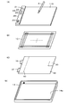
- FIG. 3 is an exploded configuration diagram for explaining a hardware configuration example of the handwriting input device 1 of this embodiment.
- the handwriting input device 1 has the display board unit 11 (FIG. 3 (A)) and the electronic devices in order from the top in the direction orthogonal to the upper surface, with the surface side on which the handwriting input is input as the upper surface side.
- a position detection sensor 12 (FIG. 3 (B)) for detecting a position indicated by the pen 2, a shield sheet 13 (FIG. 3 (C)), and a case 14 (FIG. 3 (D)) are provided.
- the case 14 is formed of, for example, synthetic resin or metal, and has a thin box shape having a storage space 14a whose upper surface is an opening.
- the display board portion 11, the position detection sensor 12, and the shield sheet 13 are housed in the storage space 14a of the case 14 so as to be overlapped with each other.
- the display board unit 11 is an example of a display unit, and is a display surface 11D that displays information such as writing information and drawing information handwritten by the user as an image by a physical phenomenon change according to the handwriting input. Be prepared.
- the information displayed on the display surface 11D is referred to as an image displayed on the display surface 11D.
- the images displayed on the display surface 11D of the display board unit 11 visually collectively display the images displayed in the entire display area of the display surface 11D when a predetermined operation is performed on the handwriting input device 1. It is configured so that it can be erased.
- the display board unit 11 is configured to use a pressure-sensitive cholesteric liquid crystal layer.
- FIG. 2 shows a partial cross-sectional view of the display board unit 11.
- two flexible transparent substrates 111 and 112 are arranged through predetermined gaps. Electrodes 113 and 114 are arranged on the surfaces of the two transparent substrates 111 and 112 facing each other, respectively.
- the pressure-sensitive cholesteric liquid crystal layer 115 is arranged in the gap between the electrodes 113 and 114 of the two transparent substrates 111 and 112.
- the display surface 11D is the upper surface of the transparent substrate 111 in this example. Therefore, the pressure-sensitive cholesteric liquid crystal layer 115 is arranged so as to face the display surface 11D.
- the flexible transparent substrates 111 and 112 are distorted to the applied pressure. Correspondingly, it causes a change in the arrangement of the liquid crystal molecules of the cholesteric liquid crystal layer 115. Then, the reflectance of the liquid crystal at the position where the pressure is applied and the arrangement change occurs changes, is formed and held on the display board portion 11 as a visible image, and is visually recognizable on the display surface 11D. appear. In this way, the reflectance of the liquid crystal at the portion where the pressure is applied changes on the display board unit 11, so that an image is formed without power consumption and displayed on the display surface 11D, due to the bistability of the liquid crystal. Be maintained.
- the display board unit 11 forms and displays an image even when pressure is applied to the display surface 11D by something other than the electronic pen 2.
- the display board portion 11 aligns the liquid crystal molecules of the pressure-sensitive cholesteric liquid crystal layer 115 in a predetermined arrangement, whereby the liquid crystal molecules are held on the display surface 11D. All the images are visually erased at once.
- the position detection sensor 12 is provided on the back side of the display board unit 11 so that the display area of the display surface 11D and the position detection sensor 12 position detection area overlap each other. Therefore, the display surface 11D of the display board unit 11 also serves as an input surface for inputting a position instruction to the position detection sensor 12.
- the position detection sensor 12 is configured to detect the position of the pen tip of the electronic pen 2 when handwritten input is performed, and to generate electronic data corresponding to the handwritten input information using the position detection coordinates as time series data. Has been done.
- the position detection sensor 12 in this example, an electromagnetic induction type position detection sensor is used. The details of the configuration of the position detection sensor 12 will be described later, but the position detection sensor 12 is configured to include a large number of loop coils for transmitting a signal to the electronic pen 2 and receiving a signal from the electronic pen 2.
- the shield sheet 13 is a conductive sheet formed of, for example, ITO (Indium Tin Oxide), zinc oxide, tin oxide, or the like, to which an electromagnetic sheet made of a magnetic material is bonded to the position detection sensor 12. It prevents unnecessary signals from being mixed in and also eliminates leakage of magnetic flux generated from the position detection sensor 12.
- the shield sheet 13 is provided so as to cover the entire surface of the position detection sensor 12 on the side opposite to the display surface 11D side that also serves as the instruction input surface.
- the position detection sensor 12 of the shield sheet 13 is provided with a position detection circuit 30 and a device control circuit 40 constituting an electronic circuit portion on the opposite side. Be done.
- the position detection circuit 30 forms electronic data including coordinate data of the position indicated by the electronic pen 2, pen pressure information, and the like, based on the output from the position detection sensor 12.
- the device control circuit 40 realizes a control function of temporarily storing the electronic data generated by the position detection circuit 30 in a memory and sending the stored electronic data to the mobile terminal 3 at a timely timing. Therefore, as will be described later, the device control circuit 40 includes a memory and a transmission circuit, and a transmission antenna AT is provided for the transmission circuit.
- the transmission circuit is configured as a communication unit that performs short-range wireless communication of the Bluetooth (registered trademark) standard, and the handwriting input device 1 and the mobile terminal 3 pass through a wireless communication path by this short-range wireless communication. Communicate.
- the transmission antenna AT is provided outside the area covered by the shield sheet 13 so that electronic data can be appropriately transmitted to the mobile terminal 3.
- the device control circuit 40 includes an erasing circuit that generates a low voltage pulse for erasing the image displayed on the display surface 11D of the display board unit 11, and displays by a point voltage pulse from the erasing circuit. The erasing timing of the image displayed on the surface 11D is controlled.
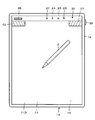
- the handwriting input device 1 of the first embodiment includes an operation button 21 as shown in FIGS. 1 and 3 (A).
- the operation button 21 visually performs a predetermined operation of collectively erasing the images displayed on the display surface 11D of the display board unit 11. Construct the means of.
- the operation button 21 also has a function as a power button of the handwriting input device 1, and each time the operation button 21 is pressed, the power of the handwriting input device 1 is repeatedly turned on and off. It is configured as follows.
- the operation button 21 is configured to also serve as a transfer button that generates a trigger for transmitting (transferring) electronic data stored in the memory to the mobile terminal 3. There is.
- the operation button 21 is provided on the panel 20 outside the display area of the display board unit 11, in this example, the upper area of the display board unit 11.
- the panel 20 has a power indicator 22 for notifying the user of power on / off, a communication indicator 23 for notifying the communication status with the mobile terminal 3, and a memory when the power is turned off. Is provided with a memory indicator 24 that notifies whether or not the electronic data is still stored in the memory.
- these indicators 22, 23, and 24 are composed of LEDs (Light Emmitting Diodes), which are examples of semiconductor light emitting elements that display the power on / off state by the light emission display.
- the panel 20 is provided with a beep speaker 25 as an example of a sound emitting means for notifying the communication status and the storage holding status of the memory by sound.
- the operation buttons 21, indicators 22, 23, 24 and the beep speaker 25 provided on the panel 20 are connected to the device control circuit 40 through the connection connector 15 (FIG. 3 (C)).
- the mobile terminal 3 has a function of receiving the electronic data transmitted from the handwriting input device 1 and transferring it to the personal computer 4.
- the mobile terminal 3 performs a predetermined process, for example, a process of assigning a page number to the electronic data based on the delimiter information, on the electronic data received from the handwriting input device 1. After that, it will be transferred to the personal computer 4.
- the mobile terminal 3 and the personal computer 4 are connected through the communication network 5.
- the communication network 5 can be configured to include a public network including the Internet and a mobile phone network. Further, the communication network 5 may be a wireless LAN using Wi-Fi (registered trademark). Further, the communication network 5 may be configured as a LAN that connects the personal computer 4 and the mobile terminal 3 by wire.
- the handwriting input device 1 may be configured to directly transmit electronic data to the personal computer 4.
- the processing function of the mobile terminal 3 may be provided by either the handwriting input device 1 or the personal computer 4.
- FIG. 4 is a diagram showing an equivalent circuit of the electronic pen 2 in this embodiment and an electronic circuit configuration example of the electronic pen 2 and a handwriting input device 1 that performs position detection and pen pressure detection by an electromagnetic induction method.
- the handwriting input device 1 of this embodiment is equipped with a battery (not shown in FIG. 4) as a power source, and as described above, the power is turned on and off alternately by pressing the operation button 21. It has a repeating configuration.
- the handwriting input device 1 of the example of FIG. 4 includes a display board unit 11, a position detection sensor 12, an operation button 21, indicators 22, 23, 24, and a beep speaker 25, and has a position. It includes a position detection circuit 30 connected to the detection sensor 12 and a device control circuit 40.
- the position detection sensor 12 is formed by stacking the X-axis direction loop coil group 121 and the Y-axis direction loop coil group 122, and sequentially connects the loop coil of one of the two loop coil groups 121 and 122.
- a selection circuit 123 for selection is provided.
- the electronic pen 2 includes a signal control circuit composed of an IC 200, and a drive voltage for driving the IC 200 is transmitted from an exciting coil 124 provided in the position detection sensor 12 of the handwriting input device 1. It is configured to be obtained from the excitation signal.
- the loop coils 121 and 122 of the position detection sensor 12 are described as being used only for receiving the electromagnetic coupling signal from the electronic pen 2, but are electromagnetically coupled with the electronic pen 2.
- the signal control circuit provided in the electronic pen 2 can be driven instead of the exciting coil 124.
- a signal such as predetermined control data is transmitted to the signal control circuit provided in the electronic pen 2.
- the exciting coil 124 is arranged so as to surround the X-axis direction loop coil group 121 and the Y-axis direction loop coil group 122.
- the exciting coil 124 has two turns, but in reality, it has a larger number of turns, for example, 8 to 10 turns.
- the exciting coil 124 is connected to the drive circuit 32, and the drive circuit 32 is connected to the oscillation circuit 31 that oscillates at a predetermined frequency fo.
- the drive circuit 32 is controlled by a position detection control unit 300 provided in the position detection circuit 30, for example, composed of a microprocessor.
- the position detection control unit 300 controls the drive circuit 32 to control the supply of the oscillation signal of the frequency fo from the oscillation circuit 31 to the exciting coil 124, and transmits the signal from the exciting coil 124 to the electronic pen 2. To control.
- the selection circuit 123 is selectively controlled by the position detection control unit 300 to select one loop coil.
- the induced voltage generated in the loop coil selected by the selection circuit 123 is supplied to the position detection circuit 30.
- the process of detecting the coordinates (X coordinate and Y coordinate) of the indicated position by the electronic pen 2 is performed under the control of the position detection control unit 300, and the position detection control unit 300 uses the electronic pen. Generate the coordinate data of the position indicated by 2.
- the position detection control unit 300 also detects the interruption and discontinuity of the signal from the electronic pen 2 as a digital signal of several bits in addition to the detection of the indicated position by the electronic pen 2 to detect the writing pressure. Then, the position detection control unit 300 generates electronic data by associating the detected position information by the electronic pen 2 with the detected pen pressure information, and supplies the electronic data to the device control circuit 40.
- the device control circuit 40 erases the image of the memory 41 that stores and holds the electronic data from the position detection circuit 30, the short-range communication unit 42 for wireless communication with the mobile terminal 3, and the display surface 11D of the display board unit 11. It includes an erasing circuit 43 that generates a low voltage pulse, and a control circuit 44 that is composed of, for example, a microprocessor. Then, as described above, the operation buttons 21, the indicators 22, 23, 24, and the beep speaker 25 are connected to the device control circuit 40.
- a power supply voltage is constantly supplied from the battery to the control circuit 44 of the device control circuit 40. However, when the power is turned off, the control circuit 44 is in the standby state, which saves power.
- the memory 41 is configured as a non-volatile memory that stores and holds stored electronic data unless it is erased.
- the memory 41 may be configured as a volatile memory so as to constantly back up the power supply from the battery.
- the control circuit 44 of the device control circuit 40 monitors the pressing operation of the operation button 21, and in response to the pressing operation, power on / off control, erasing control of the image on the display surface 11D of the display board unit 11, and the memory 41. Execute the process. In that case, the control circuit 44 also monitors the communication status with the mobile terminal 3 through the short-range communication unit 42 when the operation button 21 is pressed, and the storage status of the electronic data in the memory 41, and uses the monitoring result as the monitoring result. Depending on the situation, different processes are executed.
- the control circuit 44 controls the light emitting state of the power indicator 22 based on the monitoring result of the pressing operation of the operation button 21, and is based on the monitoring result of the communication status with the mobile terminal 3 through the short-range communication unit 42.
- the light emitting state of the communication indicator 23 is controlled.
- the control circuit 44 controls the light emitting mode of the memory indicator 24 based on the communication status with the mobile terminal 3 through the short-range communication unit 42 and the storage status of the electronic data of the memory 41.
- the control circuit 44 controls the light emitting modes of the indicators 22 to 24, and also controls to emit a beep sound from the beep speaker 25 at a necessary timing.
- the circuit configuration of the electronic pen 2 is as shown by being surrounded by a dotted line in FIG. That is, the capacitor 202 is connected in parallel with the coil 201 as the inductance element to form the resonance circuit 203. Then, the switch 204 is connected in parallel with the resonance circuit 203.
- the switch 204 is configured to be on / off controlled by the IC 200. When the switch 204 is off, the resonance circuit 203 resonates with respect to the signal from the position detection sensor 12. However, when the switch 204 is on, the capacitor 202 connected in parallel to the coil 201 is short-circuited, and the resonance operation with respect to the signal from the position detection sensor 12 by the resonance circuit 203 is turned off.
- the IC 200 obtains the AC signal received by electromagnetic induction from the position detection sensor 12 of the handwriting input device 1 in the resonance circuit 203 by rectifying it in the rectifier circuit (power supply circuit) 207 including the diode 205 and the capacitor 206. It is configured to operate according to the power supply voltage Vcc.
- the IC 200 is connected to the resonance circuit 203 via a capacitor 208, and monitors the operating status of the resonance circuit 203. By monitoring the operating status of the resonant circuit 203, the IC 200 uses the electromagnetic coupling status of the position detection sensor 12 with the exciting coil 124, or, although the description is omitted in this example, two loop coil groups 121 and 122 are used. Then, a signal such as control data transmitted from the position detection sensor 12 can be detected to perform desired operation control.
- the electronic pen 2 of this embodiment includes a pen pressure detection circuit including a pressure sensitive element that detects the pen pressure applied to the pen tip as, for example, the capacitance Cv of a variable capacitance capacitor. As shown in FIG. 4, this capacitance variable capacitor is connected to the IC 200, and the IC 200 is configured to be able to detect the capacitance Cv according to the writing pressure.
- the IC 200 detects the writing pressure in the electronic pen 2 from the value of the capacitance Cv. Then, the IC 200 converts the detected pen pressure into, for example, an 8-bit digital signal, and controls the switch 204 by the digital signal corresponding to the pen pressure, so that the pen pressure information is used as additional information by a handwriting input device. It is transmitted to the position detection sensor 12 of 1.
- the position detection control unit 300 drives the drive circuit 32 and transmits a signal from the exciting coil 124 to the electronic pen 2 for a predetermined time.
- the position detection control unit 300 sequentially selects one loop coil of the X-axis direction loop coil group 121 in the selection circuit 123, and transmits a burst-shaped signal to the electronic pen 2.
- the electronic pen 2 receives the burst-shaped signal in the resonance circuit 203 and returns it to the position detection sensor 12 of the handwriting input device 1.
- the position detection control unit 300 obtains the X coordinate value of the position indicated by the electronic pen 2 by detecting the returned burst-shaped signal as a position detection signal.
- the position detection control unit 300 performs the same processing on the Y-axis direction loop coil group 122 to obtain the Y coordinate value of the position indicated by the electronic pen 2.
- the position detection control unit 300 of the position detection circuit 30 continues from the exciting coil 124 for a predetermined time or longer in order to detect the pen pressure information as additional information from the electronic pen 2 after detecting the indicated position of the electronic pen 2.
- the transmission / reception is continuously performed a number of times according to the number of bits of the digital signal of the additional information at the same timing as when the coordinates are detected.
- the IC 200 of the electronic pen 2 detects the position of the handwriting input device 1 by the digital signal of the additional information consisting of the pen pressure information obtained corresponding to the capacitance Cv of the capacitance variable capacitor constituting the pen pressure detecting means.
- the switch 204 is on / off controlled in synchronization with the transmission / reception of the signal from the sensor 12.
- the resonant circuit 203 can return the signal transmitted from the position detection sensor 12 to the position detection sensor 12, so that the loop coil of the position detection sensor 12 receives this signal.
- the switch 204 when the switch 204 is on, the resonance circuit 203 is in a state in which the resonance operation is prohibited. Therefore, no signal is returned from the resonance circuit 203 to the position detection sensor 12, and the position detection sensor 12 The loop coil does not receive a signal.
- the position detection control unit 300 of the position detection circuit 30 receives a plurality of bits of digital signals according to the pen pressure information by determining the presence or absence of a received signal at a number of times corresponding to the number of bits of the digital signal of the additional information.
- the pen pressure information from the electronic pen 2 can be detected. Therefore, the electronic pen 2 transmits the pen pressure information as an ASK (Amplitude Shift Keying) modulated signal to the position detection sensor 12 of the handwriting input device 1.
- ASK Amplitude Shift Keying
- the handwriting input device 1 when the handwriting input is performed on the display surface 11D by the electronic pen 2 while the power is on, an image corresponding to the handwriting input is formed on the display surface 11D of the display board unit 11 and displayed.
- the position of the pen tip of the electronic pen 2 is detected by the position detection sensor 12, and the electronic data corresponding to the display image on the display surface 11D, which consists of the time-series data of the detected position information, is stored in the memory 41. It is stored in memory.
- the handwriting input device 1 determines whether or not the mobile terminal 3 and the own device can perform short-range wireless communication.
- the handwriting input device 1 is connected to the mobile terminal 3 depending on whether or not pairing is achieved during communication. Determine if short-range wireless communication is possible.
- the handwriting input device 1 determines that communication with the mobile terminal 3 is possible (confirms that communication with the mobile terminal 3 is possible)
- the electronic data stored in the memory 41 is stored.
- Delimited information for example, page breaks are added to the data and transmitted to the mobile terminal 3.
- the state in which short-range wireless communication is possible is notified to the user by turning on the communication indicator 23.
- the handwriting input device 1 completes the transmission of the electronic data stored and held in the memory 41, the communication indicator 23 is turned off and the electronic data in the memory 41 is erased.
- the handwriting input device 1 supplies a low voltage pulse from the erasing circuit 43 to the display board unit 11 to be formed on the display surface 11D for display. The images are visually erased at once for the entire display surface. Then, in this embodiment, the handwriting input device 1 turns off the power.
- the handwriting input device 1 determines that communication with the mobile terminal 3 is not possible in this embodiment (it cannot be confirmed that communication with the mobile terminal 3 is possible), the handwriting input device 1 cannot confirm that communication with the mobile terminal 3 is possible.
- the electronic data to which the delimiter information is added is not erased from the memory 41, but is kept in the memory 41. Then, in this embodiment, the handwriting input device 1 notifies by blinking the communication indicator 23 that short-range wireless communication with the mobile terminal 3 is impossible, and also blinks the memory indicator 24 to transmit. The user is notified that the electronic data is stored and held in the memory 41 without being stored.
- the handwriting input device 1 supplies a low voltage pulse from the erasing circuit 43 to the display board unit 11, and visually displays the images formed and displayed on the display surface 11D collectively for the entire display surface. To erase it. Then, the power is turned off, and the power supply to the position detection sensor 12, the position detection circuit 30, and the device control circuit 40 is turned off.
- the control circuit 44 may be configured to blink the communication indicator 23 and maintain the display control for blinking the memory indicator 24 even after the power is turned off.
- the electronic data held in the memory 41 is stored in the memory 41 when the operation button 21 is pressed after the new electronic data by the new handwriting input is additionally stored, or in the memory 41.
- the operation button 21 is pressed before the new electronic data is stored in the memory, if communication is possible, if there is new electronic data, the handwriting input device 1 to the mobile terminal 3 together with the new electronic data. Will be sent to. Then, after the transmission is completed, the memory 41 is configured to be erased.
- new delimiter information is also added to the electronic data of the image by the new handwriting input, and the data is stored in the memory without being transmitted. It is possible to distinguish it from the electronic data that was retained.
- the operation button 21 is set to accept an operation mode different from the normal operation mode, for example, a long press of the operation button 21 from the user, and the operation button 21 is notified.
- the long press operation is a press operation having a second time length longer than the first time length when the short press operation of the operation button 21 having a first time length or less is a predetermined operation. It is said that.
- the handwriting input device 1 of this embodiment when the operation button 21 is pressed and communication is not possible, the remaining capacity of the memory 41 is insufficient and it becomes difficult to store new electronic data.
- the image displayed on the display surface 11D of the display board unit 11 is not erased and is handwritten.
- the power of the input device 1 is left on, and the memory indicator 24 and the beep speaker 25 are used to notify the user to that effect.
- the user Upon receiving this notification, the user creates a situation in which communication between the handwriting input device 1 and the mobile terminal 3 is possible. Then, the handwriting input device 1 notifies the user that communication has become possible by the communication indicator 23. Therefore, when the user presses and holds the operation button 21 in this example, the handwriting input device 1 is stored and held in the memory 41. It is configured so that the electronic data can be transmitted to the mobile terminal 3.
- the power may be turned off without leaving the power on and without erasing the image on the display surface 11D.
- the memory indicator 24 notifies that the memory 41 holds electronic data. Therefore, when the operation button 21 is normally pressed to turn on the power, the display surface is displayed. Since it is known that it is necessary to transmit the electronic data of the memory 41 in combination with the fact that the image is displayed on the 11D, the user creates a communicable environment, presses and holds the operation button 21, and presses and holds the operation button 21 of the memory 41. The electronic data may be transmitted to the mobile terminal 3 so that the displayed image can be erased.
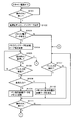
- FIGS. 5 to 8 shows the case where the power of the handwriting input device 1 is started from the off state.
- the control circuit 44 first determines whether or not the operation button 21 has been pressed (step S101), and when it determines that the operation button 21 has not been pressed, waits for the operation button 21 to be pressed. When it is determined in step S101 that the operation button 21 has been pressed, the control circuit 44 turns on the handwriting input device 1 and turns on the power indicator 22 (step S102).
- control circuit 44 determines whether or not the electronic data is stored and held in the memory 41 (step S103), and when it is determined that the electronic data is stored and held in the memory 41, the memory indicator 24 blinks. At the same time, a beep sound is emitted from the beep speaker 25 (step S104).
- control circuit 44 determines whether or not the operation button 21 has been pressed and held (step S105), and when it determines that the operation button 21 has not been pressed and held, the control circuit 44 displays on the display surface 11D by the electronic pen 2. It is determined whether or not the instruction input is detected (step S106). When it is determined in step S106 that the instruction input on the display surface 11D by the electronic pen 2 is not detected, the control circuit 44 returns the process to step S105.
- step S105 When it is determined in step S105 that the operation button 21 has been pressed and held for a long time, the control circuit 44 and the mobile terminal 3 depending on whether or not the pairing of the communication between the short-range communication unit 42 and the mobile terminal 3 can be confirmed. It is confirmed whether wireless communication between the two is possible (step S121 in FIG. 6), and it is determined whether or not wireless communication with the mobile terminal 3 is possible (step S122).
- step S122 when it is determined in step S122 that wireless communication with the mobile terminal 3 is possible, the control circuit 44 transmits the electronic data stored in the memory 41 to the mobile terminal 3 (step S123). .. Then, the control circuit 44 determines whether or not the transmission is completed (step S124), and when it is determined that the transmission is completed, erases the electronic data stored in the memory 41 (step S125). Further, the control circuit 44 turns off the blinking memory indicator 24 (step S126).
- step S124 determines whether or not a predetermined time or more has elapsed from the start of transmission (step S127), and the predetermined time or more from the start of transmission.
- step S127 determines whether or not a predetermined time or more has elapsed from the start of transmission.
- step S127 when it is determined in step S127 that a predetermined time or more has passed from the start of transmission, the control circuit 44 determines that the transmission of electronic data has failed, stops the transmission (step S128), and blinks the communication indicator 23. At the same time, a beep sound is emitted from the beep speaker 25 (step S129).
- step S122 Even when it is determined in step S122 that wireless communication with the mobile terminal 3 is not possible, the control circuit 44 determines that wireless communication with the mobile terminal 3 is not possible, and proceeds to step S129. Proceed, the communication indicator 23 blinks, and a beep sound is emitted from the beep speaker 25. Then, the control circuit 44 keeps the electronic data stored in the memory 41 (step S130).
- step S107 of FIG. 5 after step S126 and step S130, and determines whether or not the instruction input on the display surface 11D by the electronic pen 2 is detected. Further, when it is determined in step S103 of FIG. 5 that the electronic data is not stored and held in the memory 41, the control circuit 44 proceeds to step S107 and inputs an instruction input on the display surface 11D by the electronic pen 2. Determine if it has been detected.
- control is performed.
- the circuit 44 determines whether or not the instruction input by the electronic pen 2 is an erasure input such as a double line superimposed on the previously input portion (step S108).
- step S108 When it is determined in step S108 that the input is not erasure input, the control circuit 44 detects the coordinate data of the position indicated and input by the electronic pen 2, and stores the electronic data including the coordinate data and the pen pressure data in the memory 41. The memory is retained in (step S109). Further, when it is determined in step S108 that the erasure input is, the control circuit 44 deletes the electronic data of the instruction input before the erasure input such as the double line is overlapped from the memory 41 (step S110). ..
- step S111 the control circuit 44 determines whether or not the operation button 21 is pressed. Even when it is determined in step S107 that the instruction input on the display surface 11D by the electronic pen 2 is not detected, the process proceeds to step S111 to determine whether or not the operation button 21 has been pressed. Then, when it is determined in step S111 that the operation button 21 is not pressed, the control circuit 44 returns the process to step S107 and repeats the processes after this step S107.
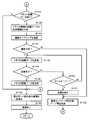
- step S111 when it is determined in step S111 that the operation button 21 is pressed, the control circuit 44 determines whether or not there is electronic data stored and held in the memory 41 (step S141 in FIG. 7). When it is determined in step S141 that there is no electronic data stored in the memory 41, the control circuit 44 proceeds to step S148 and supplies a low voltage pulse from the erasing circuit 43 to the display board unit 11. Then, the images displayed on the display surface 11D are collectively erased, and then the handwriting input device 1 is turned off (step S149).
- step S141 the image on the display surface 11D of the display board unit 11 is erased even when there is no stored data in the memory 41 because the erasure input is performed by the instruction input by the electronic pen 2. Occasionally, the electronic data at the position specified by the erasure input is erased from the memory 41, and even if the electronic data is not in the memory 41, the image instructed to be erased by the erasure input is displayed on the display surface 11D of the display board unit 11. This is because it may remain displayed.
- Step S141 when it is determined in step S141 that there is electronic data stored and held in the memory 41, the control circuit 44 newly stores and holds the electronic data after the operation button 21 is pressed and the power is turned on. (Step S142) is provided with delimiter information such as a page break mark.
- control circuit 44 confirms whether wireless communication with the mobile terminal 3 is possible depending on whether or not the pairing of communication between the short-range communication unit 42 and the mobile terminal 3 can be confirmed. Then (step S143), it is determined whether or not wireless communication with the mobile terminal 3 is possible (step S144).
- step S144 when it is determined in step S144 that wireless communication with the mobile terminal 3 is possible, the control circuit 44 transmits the electronic data stored in the memory 41 to the mobile terminal 3 (step S145). .. Then, the control circuit 44 determines whether or not the transmission is completed (step S146), and when it is determined that the transmission is completed, erases the electronic data stored in the memory 41 (step S147).
- control circuit 44 advances the process to step S148, supplies a low voltage pulse from the erasing circuit 43 to the display board unit 11, collectively erases the images displayed on the display surface 11D, and then collectively erases the images.
- the power of the handwriting input device 1 is turned off (step S149).
- step S146 determines whether or not a predetermined time or more has elapsed from the start of transmission (step S150), and the predetermined time or more from the start of transmission.
- step S150 determines whether or not a predetermined time or more has elapsed from the start of transmission.
- step S150 when it is determined in step S150 that a predetermined time or more has passed from the start of transmission, the control circuit 44 determines that the transmission of electronic data has failed, stops the transmission (step S151), and blinks the communication indicator 23. At the same time, a beep sound is emitted from the beep speaker 25 (step S152). Then, the control circuit 44 keeps the electronic data stored in the memory 41 (step S161 in FIG. 8), and blinks the memory indicator 24 (step S162).
- control circuit 44 determines whether or not there is a remaining capacity based on whether or not the remaining capacity of the memory 41 is equal to or less than a predetermined remaining capacity value (step S163).
- the predetermined remaining capacity value is a value that may cause the memory 41 to run out of capacity when new electronic data is added, and is set with a margin.
- step S163 When it is determined in step S163 that the remaining capacity of the memory 41 is not equal to or less than the predetermined remaining capacity value, the control circuit 44 proceeds to step S148 of FIG. 7 to generate a low voltage pulse from the erasing circuit 43.
- the image is supplied to the display board unit 11 to collectively erase the images displayed on the display surface 11D, and then the handwriting input device 1 is turned off (step S149).
- step S163 when it is determined in step S163 that the remaining capacity of the memory 41 is equal to or less than the predetermined remaining capacity value, the control circuit 44 does not erase the image of the display surface 11D of the display board unit 11, and the capacity of the memory 41 is not erased.
- Beep sound is emitted (step S164).
- the user is urged to transfer the electronic data of the memory 41 to the mobile terminal 3 because the remaining capacity of the memory 41 is insufficient, and the user communicates the handwriting input device 1 with the mobile terminal 3. Move to an environment where it is possible.
- the control circuit 44 determines whether or not the environment is capable of communicating with the mobile terminal 3 (step S165), and waits for the environment to be able to communicate with the mobile terminal 3. Then, when it is determined in step S165 that the environment is capable of communicating with the mobile terminal 3, the control circuit 44 turns on the communication indicator 23 and notifies the user of this (step S166). ..
- step S167 when the user's long-pressing operation of the operation button 21 is monitored (step S167) and the user's long-pressing operation of the operation button 21 is determined, all the electronic data stored and held in the memory 41 is stored in the mobile terminal. It is transmitted to 3 (step S168).
- the electronic data stored and held in the memory 41 is data for a plurality of pages separated by delimiter information.
- the electronic data stored and held in the memory 41 is for a plurality of pages, but since it is separated by the delimiter information, each page has a different page number on the mobile terminal 3 or the personal computer 4. Can be given to distinguish them.
- step S168 When the electronic data stored and held in the memory 41 is transmitted to the mobile terminal 3 in step S168, the control circuit 44 erases the electronic data stored and held in the memory 41 from the memory 41 (step S169). Then, the control circuit 44 turns off the memory indicator 24 (step S170). Following this step S170, the control circuit 44 proceeds with the process to step S148 of FIG. 7, supplies a low voltage pulse from the erasing circuit 43 to the display board unit 11, and displays the low voltage pulse on the display surface 11D. The existing images are erased all at once, and then the handwriting input device 1 is turned off (step S149).
- the electronic data sent from the handwriting input device 1 based on the operation of the operation button 21 is transmitted to the display surface 11D of the handwriting input device 1. It can be easily managed as electronic data of the image displayed on. That is, in the mobile terminal 3, even if the delimiter information is not added to the electronic data received from the handwriting input device 1, the display surface 11D of the handwriting input device 1 is given a page number to the received electronic data. It can be processed as data of the unit of the page corresponding to the image displayed in.
- the electronic data in the memory 41 is configured to be given delimiter information each time the operation button 21 is operated. Therefore, in the mobile terminal 3, this delimiter is provided. It is easy to assign page numbers by relying on information.
- the electronic data of the memory 41 is transmitted to the mobile terminal 3 which is an external device when there is a predetermined operation of pressing the operation button 21. Is possible, and then transmission is executed, and after the transmission, the electronic data is erased from the memory 41. Therefore, the electronic data corresponding to the handwritten input image is erased without being transmitted. Is avoided.
- the user visually erases the image displayed on the display surface 11D of the display board unit 11 by pressing the operation button 21.
- the above operation is executed only by performing a predetermined operation. Therefore, the user does not need to perform separate operations for erasing the image displayed on the display surface 11D of the display board unit 11 and transmitting the electronic data stored in the memory 41. .. Therefore, when a predetermined operation for visually erasing the image displayed on the display surface 11D of the display board unit 11 and an operation for transmitting electronic data stored in the memory are performed separately.
- a predetermined operation for visually erasing the image displayed on the display surface 11D of the display board unit 11 and an operation for transmitting electronic data stored in the memory are performed separately.
- a mistake such as forgetting to transmit the electronic data.
- a predetermined operation means for visually erasing the image displayed on the display surface 11D of the display board unit 11 and electronic data stored in the memory 41 Since it is not necessary to separately provide the operation means for the operation of the handwriting input device 1, there is also an effect that the configuration of the handwriting input device 1 is simplified.
- the handwriting input device 1 of the first embodiment described above when the electronic data of the memory 41 cannot be transmitted to the mobile terminal 3 which is an external device at the time of a predetermined operation by pressing the operation button 21, the electronic data of the memory 41 cannot be transmitted. Even if the image displayed on the display surface 11D of the display board unit 11 is erased, the electronic data in the memory 41 is not erased, but the delimiter information is added and the image is stored and held in the memory 41. There is. Then, the handwriting input device 1 uses the indicators 23 and 24 and the beep speaker 25 to notify the user of the situation in which communication was not possible at that time and that the electronic data is still stored in the memory 41. To.
- the user can grasp the communication status between the handwriting input device 1 and the mobile terminal 3 and the storage state of the memory 41, so that the communication status between the handwriting input device 1 and the mobile terminal 3 can be communicated. It is possible to take appropriate measures such as transmitting the electronic data of the memory 41 by pressing and holding the operation button 21 in addition to the state of.
- the handwriting input device 1 of the first embodiment described above cannot transmit the electronic data of the memory 41 to the mobile terminal 3 which is an external device at the time of a predetermined operation by pressing the operation button 21, and the memory
- the image displayed on the display surface 11D of the display board unit 11 cannot be erased and is used. It is designed to be a warning notification to the person.
- the indicators 23 and 24 are made to display a warning such as a blinking display, and the beep speaker 25 emits a beep sound to call attention. ing.
- the user when the user receives this warning notification, it is necessary to transmit the electronic data stored in the memory 41 to the external device to secure the remaining capacity of the memory 41 for new handwriting input. You can recognize that. Therefore, the user makes the communication status between the handwriting input device 1 and the mobile terminal 3 in a communicable state, and presses and holds the operation button 21 to transmit the electronic data of the memory 41. You can take action.
- the predetermined operation for erasing the image displayed on the display surface 11D of the display board unit 11 and transmitting the electronic data from the memory 41 is the pressing operation of the operation button 21.
- the operation of the operation button 21 as the operation of is also configured to be detected as a power on / off operation.
- the operation mode for the operation button 21 is configured so that a predetermined operation for erasing the image displayed on the display surface 11D of the display board unit 11 and a power on / off operation are different operation modes. You may.
- a short-time pressing operation of the operation button 21 having a first time length or less is a predetermined operation
- a pressing operation having a second time length longer than the first time length is a power on / off operation. You may do it.
- the operation for transmitting the stored electronic data without being transmitted to the memory 41 is not a long press as in the above-described embodiment in order to distinguish it from the power on / off operation.
- the pressing operation may be performed twice in succession for a short period of time equal to or less than the first time length.
- the operation button 21 for a predetermined operation for erasing the image displayed on the display surface 11D of the display board unit 11 is configured to also serve as the power button.
- the button may be another operation button.
- the memory 41 has a capacity for a plurality of pages of the image displayed on the display surface 11D of the display board unit 11 of the handwriting input device 1, but the storage capacity of the memory 41 is used.
- One page of the image displayed on the display surface 11D of the display board unit 11 of the handwriting input device 1 may be used.
- the electronic data of the memory 41 cannot be transmitted even though the operation button 21 is pressed, it is displayed on the display surface 11D of the display board unit 11 each time. Be careful by disabling the erasure of the image, making it a warning notification to the user, displaying warnings such as blinking indicators 23 and 24, and emitting a beep sound by the beep speaker 25. Try to arouse.
- the mobile terminal 3 is displayed on the display surface 11D. Since the electronic data for each page of the image is transmitted, the mobile terminal 3 delimits the page number and the like each time the electronic data is received, even if the delimiter information is not added to the electronic data. It is possible to add the indicated information. That is, the handwriting input device 1 has an advantage that it is not necessary to add delimiter information to the electronic data of the memory 41.
- the indicators 22 to 24 composed of the semiconductor light emitting element are monochromatic light emitting elements, and display the status notification depending on the difference in the light emitting mode such as lighting and blinking.
- a state notification display may be performed by changing the light emitting mode by changing the light emitting color.
- the predetermined operation for erasing the image displayed on the display surface is the pressing operation of the operation button 21.
- the handwriting input device of the second embodiment uses an instruction input operation by an electronic pen in a predetermined position range within the position detection area of the position detection sensor as a predetermined operation without providing such an operation button. This is an example of the case where it is configured as follows.
- FIG. 9 is a diagram for explaining the handwriting input device 1A of the second embodiment.
- the handwriting input device 1A of the second embodiment does not have an operation button 21 as a hardware configuration, and an instruction input by an electronic pen in a predetermined position range within the position detection area of the position detection sensor is provided.
- the operation is configured in the same manner as the handwriting input device 1 of the first embodiment, except that the operation is used as a predetermined operation. Therefore, in the following description, the same parts as the handwriting input device 1 of the first embodiment will be described using the same reference numerals.
- FIG. 9 is a view of the handwriting input device 1A of the second embodiment as viewed from above in the direction orthogonal to the display surface 11D. Also in the handwriting input device 1A of the second embodiment, the position detection sensor 12 is arranged on the back side of the display board portion 11 in a state where the display area of the display surface 11D and the position detection area overlap.
- a power button 26 is provided on the side of the case 14.
- the control circuit 44 of the device control circuit 40 controls each time the power button 26 is operated so as to alternately turn the power on and off of the handwriting input device 1A.
- the panel 20A is provided outside the display area of the display surface 11D and above the display surface 11D in FIG. 9, and the panel 20A is provided on the panel 20A in the same manner as in the first embodiment.
- a power indicator 22, a communication indicator 23, a memory indicator 24, and a beep speaker 25 are provided.
- the predetermined operation receiving area 51 is used to receive the predetermined operation for the purpose as an operation through the electronic pen 2.
- the image displayed on the display surface 11D is erased by the instruction input using the electronic pen 2 to instruct any position in the predetermined operation reception area 51 for a short time, that is, the one-tap operation by the electronic pen 2.
- the control circuit 44 of the device control circuit 40 is made to recognize.
- the control circuit 44 is electronic in the predetermined operation reception area 51.
- a plurality of short-time instruction inputs by the pen 2, for example, two consecutive inputs, that is, a double tap operation is recognized as a transmission instruction operation of electronic data held without being transmitted to the memory 41.
- the instruction operation by the electronic pen 2 in the predetermined operation reception area 51 is not limited to one tap or double tap, and any operation input can be used as long as the control circuit 44 is a distinguishable operation input. You may. Further, the power button 26 may not be provided, and the instruction operation distinguishable from other instruction operations by the electronic pen 2 in the predetermined operation reception area 51 may be recognized as the power on / off operation.
- the handwriting input device 1A of the second embodiment is configured to be able to control the operation and non-operation of the device control circuit 40. That is, in the handwriting input device 1A of the second embodiment, in order to receive the control instruction by the user who operates or does not operate the device control circuit 40, in this example, the upper part of the panel 20 side, for example, the leftmost rectangle.
- the area is a control instruction receiving area 52 that receives the control instruction by the user as an instruction operation through the electronic pen 2.
- the panel 20 is provided with an indicator 27 for notifying the operating state (on, off) of the device control circuit 40.
- the indicator 27 is also composed of a semiconductor light emitting element like the indicators 22 to 24.
- the control circuit 44 of the device control circuit 40 receives the power supply voltage to the device control circuit 40 each time the instruction input operation is performed by the electronic pen 2 in the control instruction receiving area 52.
- the supply is controlled so that the operation and non-operation of the device control circuit 40 are alternately repeated. Note that the control circuit 44 is in the standby state even when the device control circuit 40 is inactive, and the power supply voltage is always supplied as in the first embodiment.
- the indicator 27 is turned on by the control circuit 44 and the device control circuit 40 operates.
- the control circuit 44 turns off the indicator 27.
- the handwriting input device 1A of the second embodiment an image is formed and displayed on the display surface 11D of the display board unit 11, but it is not necessary to transfer the electronic data of the image to the external device. Can realize a usage mode that can reduce battery consumption.
- the display surface 11D of the display board unit 11 does not include the predetermined operation reception area 51 and the control instruction reception area 52, and only the position detection area of the position detection sensor 12 is included in the predetermined operation reception area 51 and the sensor control. It may be configured to include the instruction receiving area 52.
- the position detection sensor 12 is not configured to detect the instruction input to the predetermined operation reception area 51 or the control instruction reception area 52, but corresponds to the predetermined operation reception area 51 or the control instruction reception area 52. Therefore, a sensor for detecting an operation on the area, such as a pressure sensor or a touch sensor, may be separately provided. In that case, the operation input to the predetermined operation reception area 51 or the control instruction reception area 52 may be not only the operation input by the electronic pen 2 but also the operation input by the user's finger.
- the detection circuit 30 can also control the power supply to control the on / off of the operation, an image is formed and displayed on the display surface 11D of the display board unit 11, but the electronic data of the image is externally displayed.
- a transparent sheet on which a predetermined document form is printed is prepared, and the transparent sheet is placed on the display surface 11D of the handwriting input device 1 or 1A of the above-described embodiment and printed on the transparent sheet. It is convenient to use for handwriting input on the document form.
- FIG. 10 is a diagram showing a configuration example of a system that realizes this usage.
- the user of this system creates a desired document form FM and registers it in, for example, a server device 61 including a personal computer.
- the server device 61 accepts this registration, assigns identification information (paper ID) to the received document form, and stores the data of the document form in the database.
- identification information paper ID
- the server device 61 assigns unique identification information as a paper ID, for example, a barcode.
- the database of the server device 61 includes area coordinate data indicating an input area for handwritten information, attribute data of information to be input in the input area for handwritten information, and the like.
- the area coordinate data indicating the input area of the handwritten information included in the document form corresponds to the coordinate data of the position detection area of the position detection sensor 12 of the handwriting input device 1.
- the registered document form is printed on the transparent sheet 63 by the printer 62.
- a barcode as an example of the paper ID given by the server device 1 is printed at a predetermined position on the transparent sheet 63.
- the transparent sheet 63 is placed on the display surface 11D of the handwriting input device 1 or 1A.
- the handwriting input device 1 or 1A of this example is provided with a means for locking the transparent sheet 63 on the display surface 11D, for example, a clip member (not shown), and the transparent sheet is provided by the clip member. 63 is locked on the display surface 11D.
- the handwriting input device 1 or 1A of this example is further provided with a bar code reader (not shown) for reading the bar code printed on the transparent sheet 63, and the control circuit 44 of the device control circuit 40 is provided.
- the bar code information read by this bar code reader is stored in the memory 41 as a paper ID corresponding to electronic data.
- the user of the handwriting input device 1 or 1A uses the electronic pen 2 to perform handwriting input in the area where input is required in the document form of the transparent sheet 63. Then, the handwritten input image is formed and displayed on the display surface 11D of the display board unit 11, and the position of the pen tip of the electronic pen 2 is detected by the position detection sensor 12 and handwritten input is performed in the memory 41. Electronic data corresponding to the image is stored.
- the control circuit 44 of the device control circuit 40 of the handwriting input device 1 can communicate with the mobile terminal 3. After that, the electronic data stored in the memory 41 is transmitted to the mobile terminal 3 with a paper ID added. Then, the control circuit 44 performs a process of erasing the image displayed on the display surface 11D after the transmission is completed. Then, the handwritten input images written in each of the input fields of the document form of the transparent sheet 63 are deleted, and each of the input fields of the document form becomes blank. That is, the next user can input by handwriting in the blank of the same document form.
- the mobile terminal 3 is pre-installed with an application program for performing necessary processing in this system.
- the mobile terminal 3 receives the paper ID and electronic data from the handwriting input device 1 or 1A, it stores them in the buffer memory and transmits the received paper ID information to the server device 1 through the communication network 64.
- the mobile terminal 3 displays the document form based on the display data on the display screen and the handwritten input device 1 or 1A. Display the handwritten information in the blank of the document form based on the electronic data received from.
- the mobile terminal 3 adds a paper ID to the electronic data received from the handwriting input device 1 or 1A stored in the buffer memory, for example, based on the transfer instruction of the user of the mobile terminal 3. It sends to the server device 1 and requests the storage of the entered data. At this time, a page number and a time stamp are added to the electronic data transmitted from the mobile terminal 3 to the server device 1. As a result, the server device 61 can identify even the handwritten input information of the same document form based on the page number and the time stamp.
- the server device 1 stores the electronic data associated with the paper ID received from the mobile terminal 3 in the handwritten information storage unit in association with the received paper ID.
- the document is formed by placing the transparent sheet 63 on which the predetermined document form is printed on the display surface 11D.
- Handwritten input information in the required input fields in the form can be collected as electronic data.
- the document form can be recognized by the paper ID, and the electronic data can be managed by the delimiter information such as the page number. Therefore, this system is very useful for applications such as handwriting input in a predetermined input field of a specific document form such as a questionnaire in a hospital or a member registration sheet in a store.
- the display unit is composed of a display board unit using a pressure-sensitive cholesteric liquid crystal layer, but the display unit is not limited to this example. Absent.
- the display unit may be composed of the magnetic sheet 16 as shown in FIG.
- a position detection sensor 12 is arranged below the magnetic sheet 16 (on the back surface side) so as to overlap the magnetic sheet 16 in a direction orthogonal to the display surface. ..
- the magnetic sheet 16 is a microcapsule 163 in which a magnetic material powder such as iron powder 163Fe (shown as a black dot in FIGS. 11 (A) and 11 (B)) is mobilably confined.
- a magnetic material powder such as iron powder 163Fe (shown as a black dot in FIGS. 11 (A) and 11 (B)) is mobilably confined.
- a large number of them are confined in a gap between a sheet-shaped resin base material 161 made of, for example, PET (Polyethylene Terephthalate) and a sheet-shaped resin base material 162, and are formed in a sheet shape.
- at least the sheet-shaped resin base material 161 is a transparent material.
- the surface 161a of the sheet-shaped resin base material 161 of the magnetic sheet 16 serves as a display surface.
- the iron powder 163Fe in each microcapsule 163 exists at an irregular arbitrary position as shown in FIG. 11 (B).
- the surface of the magnetic sheet 16, that is, the display surface, is in a state of a predetermined ground color, for example, white.
- the iron powder 163Fe in the microcapsules 163 near the position where the magnetic poles are close to or come into contact is shown in FIG. ), It is attracted to the magnetic pole side. Therefore, at a position where the magnetic poles are close to each other or in contact with each other, the surface of the magnetic sheet 16, that is, the display surface exhibits the color of iron powder 163Fe, for example, black. The position of the iron powder 163Fe in the microcapsule 163 is maintained even when the magnetic poles are separated. Therefore, when the magnetic poles that are close to or in contact with the surface of the magnetic sheet 16 move, the movement locus becomes a black line and appears on the surface of the magnetic sheet 16.
- the core body 2T of the electronic pen 2 is configured to have a magnetic pole (for example, N pole) at least at the tip end portion. Therefore, when handwriting input is performed on the magnetic sheet 16 with the electronic pen 2, the movement locus appears on the surface (display surface) of the magnetic sheet 16, the handwriting input position is detected by the position detection sensor 12, and electronic data is generated. Will be done.
- a magnetic pole for example, N pole
- the state of the iron powder 163Fe in the microcapsules 163 magnetically attracted to the surface of the magnetic sheet 16 of the display unit is displayed at an irregular position shown in FIG. 11 (B). It comes with an eraser (not shown) that allows it to return to its original state.
- the eraser is configured to be able to erase the entire display area of the magnetic sheet 16 at once.
- a electrophoretic sheet-like member that encloses positively charged particles and negatively charged particles in a microcapsule and displays an image by an electrophoretic display method is used. You can also.
- the electrophoresis sheet member includes an upper electrode and a lower electrode, and a display image is formed according to the electric field applied between the upper electrode and the lower electrode. Then, in the case of this example, when the position indicated by the electronic pen is detected by the position detection sensor, the electric field at the position corresponding to the detected position of the electrophoresis sheet-like member is controlled. A display image is generated.
- an electric field for erasing is supplied between the upper electrode and the lower electrode in response to an input operation to the erasing operation button or the erasing instruction area in the detection area of the position detection sensor.
- the displayed images are configured to be erased all at once.
- the display information of the document form can be displayed separately in addition to displaying the image corresponding to the detection output of the position detection sensor. Then, by erasing the displayed images all at once and then displaying the document form prior to the handwriting input, the same usage mode as the system shown in FIG. 10 can be realized. In the case of this example, there is an advantage that the transparent sheet is also unnecessary.
- the position detection sensor uses the electromagnetic induction method, but it goes without saying that a sensor of another position detection method such as the active electrostatic coupling method can be used.
- 1,1A ... Handwriting input device 2 ... Electronic pen, 3 ... Mobile terminal, 4 ... PC, 11 ... Display board, 12 ... Position detection sensor, 21 ... Operation button, 22-24, 27 ... Indicator, 25 ... Beep Speaker, 26 ... power button, 30 ... position detection circuit, 40 ... device control circuit, 41 ... memory, 42 ... short-range communication unit, 43 ... erasing circuit, 44 ... control circuit
Landscapes
- Engineering & Computer Science (AREA)
- Theoretical Computer Science (AREA)
- General Engineering & Computer Science (AREA)
- Physics & Mathematics (AREA)
- General Physics & Mathematics (AREA)
- Human Computer Interaction (AREA)
- Nonlinear Science (AREA)
- Electromagnetism (AREA)
- Mathematical Physics (AREA)
- Chemical & Material Sciences (AREA)
- Crystallography & Structural Chemistry (AREA)
- Optics & Photonics (AREA)
- Computer Hardware Design (AREA)
- Computing Systems (AREA)
- Liquid Crystal (AREA)
- User Interface Of Digital Computer (AREA)
- Position Input By Displaying (AREA)
- Electrochromic Elements, Electrophoresis, Or Variable Reflection Or Absorption Elements (AREA)
- Devices For Indicating Variable Information By Combining Individual Elements (AREA)
Priority Applications (6)
| Application Number | Priority Date | Filing Date | Title |
|---|---|---|---|
| JP2021565375A JP7520887B2 (ja) | 2019-12-17 | 2020-11-16 | 手書き入力装置 |
| US17/732,246 US11880563B2 (en) | 2019-12-17 | 2022-04-28 | Handwriting input device |
| US18/539,970 US12229400B2 (en) | 2019-12-17 | 2023-12-14 | Handwriting input device |
| JP2024110955A JP7733780B2 (ja) | 2019-12-17 | 2024-07-10 | 手書き入力装置 |
| US19/018,935 US12613629B2 (en) | 2019-12-17 | 2025-01-13 | Handwriting input device |
| JP2025138599A JP2025169960A (ja) | 2019-12-17 | 2025-08-22 | 手書き入力装置 |
Applications Claiming Priority (2)
| Application Number | Priority Date | Filing Date | Title |
|---|---|---|---|
| JP2019227249 | 2019-12-17 | ||
| JP2019-227249 | 2019-12-17 |
Related Child Applications (1)
| Application Number | Title | Priority Date | Filing Date |
|---|---|---|---|
| US17/732,246 Continuation US11880563B2 (en) | 2019-12-17 | 2022-04-28 | Handwriting input device |
Publications (1)
| Publication Number | Publication Date |
|---|---|
| WO2021124753A1 true WO2021124753A1 (ja) | 2021-06-24 |
Family
ID=76477221
Family Applications (1)
| Application Number | Title | Priority Date | Filing Date |
|---|---|---|---|
| PCT/JP2020/042543 Ceased WO2021124753A1 (ja) | 2019-12-17 | 2020-11-16 | 手書き入力装置 |
Country Status (3)
| Country | Link |
|---|---|
| US (2) | US11880563B2 (https=) |
| JP (3) | JP7520887B2 (https=) |
| WO (1) | WO2021124753A1 (https=) |
Families Citing this family (4)
| Publication number | Priority date | Publication date | Assignee | Title |
|---|---|---|---|---|
| WO2022123885A1 (ja) * | 2020-12-10 | 2022-06-16 | 株式会社ワコム | 電子ペン、手書き入力装置及び電子ペン用芯体 |
| TWI818421B (zh) * | 2021-01-29 | 2023-10-11 | 南韓商希迪普公司 | 觸控裝置、其之驅動方法及觸控系統 |
| US12293121B2 (en) * | 2022-05-02 | 2025-05-06 | Universal City Studios Llc | Systems and methods for adjusting an image displayed via a food and/or drink container |
| US20250377685A1 (en) * | 2024-06-11 | 2025-12-11 | Shenzhen Xin Niu E-commerce Co., Ltd | Calculator with handwriting pad |
Citations (4)
| Publication number | Priority date | Publication date | Assignee | Title |
|---|---|---|---|---|
| JP2009252048A (ja) * | 2008-04-08 | 2009-10-29 | Canon Inc | 画像処理システム、画像処理装置及び画像処理方法 |
| JP2015197795A (ja) * | 2014-04-01 | 2015-11-09 | 日本電気株式会社 | 端末装置、電子ホワイトボードシステム、電子ホワイトボードの入力支援方法、及びプログラム |
| JP2017504814A (ja) * | 2013-11-01 | 2017-02-09 | ケント ディスプレイズ インコーポレイテッド | ドットパターン認識システムを備えた電子書き込み装置 |
| JP2018037033A (ja) * | 2016-09-02 | 2018-03-08 | 株式会社ワコム | 手書き情報入力装置及び手書き情報入力方法 |
Family Cites Families (4)
| Publication number | Priority date | Publication date | Assignee | Title |
|---|---|---|---|---|
| US5793360A (en) * | 1995-05-05 | 1998-08-11 | Wacom Co., Ltd. | Digitizer eraser system and method |
| US6625583B1 (en) * | 1999-10-06 | 2003-09-23 | Goldman, Sachs & Co. | Handheld trading system interface |
| US9134561B2 (en) * | 2011-11-01 | 2015-09-15 | Kent Displays Incorporated | Writing tablet information recording device |
| JP2015001751A (ja) | 2013-06-13 | 2015-01-05 | コニカミノルタ株式会社 | 手書き入力装置及び制御プログラム並びに制御方法 |
-
2020
- 2020-11-16 WO PCT/JP2020/042543 patent/WO2021124753A1/ja not_active Ceased
- 2020-11-16 JP JP2021565375A patent/JP7520887B2/ja active Active
-
2022
- 2022-04-28 US US17/732,246 patent/US11880563B2/en active Active
-
2023
- 2023-12-14 US US18/539,970 patent/US12229400B2/en active Active
-
2024
- 2024-07-10 JP JP2024110955A patent/JP7733780B2/ja active Active
-
2025
- 2025-08-22 JP JP2025138599A patent/JP2025169960A/ja active Pending
Patent Citations (4)
| Publication number | Priority date | Publication date | Assignee | Title |
|---|---|---|---|---|
| JP2009252048A (ja) * | 2008-04-08 | 2009-10-29 | Canon Inc | 画像処理システム、画像処理装置及び画像処理方法 |
| JP2017504814A (ja) * | 2013-11-01 | 2017-02-09 | ケント ディスプレイズ インコーポレイテッド | ドットパターン認識システムを備えた電子書き込み装置 |
| JP2015197795A (ja) * | 2014-04-01 | 2015-11-09 | 日本電気株式会社 | 端末装置、電子ホワイトボードシステム、電子ホワイトボードの入力支援方法、及びプログラム |
| JP2018037033A (ja) * | 2016-09-02 | 2018-03-08 | 株式会社ワコム | 手書き情報入力装置及び手書き情報入力方法 |
Also Published As
| Publication number | Publication date |
|---|---|
| US11880563B2 (en) | 2024-01-23 |
| JPWO2021124753A1 (https=) | 2021-06-24 |
| US20240111413A1 (en) | 2024-04-04 |
| JP2025169960A (ja) | 2025-11-14 |
| JP7520887B2 (ja) | 2024-07-23 |
| JP2024147642A (ja) | 2024-10-16 |
| JP7733780B2 (ja) | 2025-09-03 |
| US12229400B2 (en) | 2025-02-18 |
| US20220253210A1 (en) | 2022-08-11 |
| US20250147655A1 (en) | 2025-05-08 |
Similar Documents
| Publication | Publication Date | Title |
|---|---|---|
| JP7520887B2 (ja) | 手書き入力装置 | |
| CN108241444B (zh) | 手写信息处理设备、手写信息处理方法和计算机可读存储介质 | |
| JP3786464B2 (ja) | 画像消去方法及びスタイラス型電子筆記システム | |
| EP3579088B1 (en) | Pointing device and writing information processing device | |
| CN104423771B (zh) | 描绘装置 | |
| JP7654140B2 (ja) | 電子ペン及び手書き入力装置 | |
| GB2475928A (en) | An input system including an interactive surface for detecting a contact point and the presence of a response to an excitation signal | |
| JP2018032434A (ja) | 情報処理装置 | |
| CN119512382A (zh) | 主动笔及位置检测系统 | |
| JP2025159231A (ja) | 電子ペン、手書き入力装置及び電子ペン用芯体 | |
| US12613629B2 (en) | Handwriting input device | |
| US20240094833A1 (en) | Trajectory input system | |
| TWI920150B (zh) | 電子筆、手寫輸入裝置及電子筆用芯體 | |
| JP4650689B2 (ja) | 印刷ページ表示システム | |
| JP2025167183A (ja) | パッド付属物、仮想入力デバイス、及び入力システム |
Legal Events
| Date | Code | Title | Description |
|---|---|---|---|
| 121 | Ep: the epo has been informed by wipo that ep was designated in this application |
Ref document number: 20903558 Country of ref document: EP Kind code of ref document: A1 |
|
| ENP | Entry into the national phase |
Ref document number: 2021565375 Country of ref document: JP Kind code of ref document: A |
|
| NENP | Non-entry into the national phase |
Ref country code: DE |
|
| 122 | Ep: pct application non-entry in european phase |
Ref document number: 20903558 Country of ref document: EP Kind code of ref document: A1 |