WO2021124389A1 - 巻上機及びエレベーター - Google Patents
巻上機及びエレベーター Download PDFInfo
- Publication number
- WO2021124389A1 WO2021124389A1 PCT/JP2019/049142 JP2019049142W WO2021124389A1 WO 2021124389 A1 WO2021124389 A1 WO 2021124389A1 JP 2019049142 W JP2019049142 W JP 2019049142W WO 2021124389 A1 WO2021124389 A1 WO 2021124389A1
- Authority
- WO
- WIPO (PCT)
- Prior art keywords
- hoisting machine
- support member
- stators
- rotating body
- rotors
- Prior art date
- Legal status (The legal status is an assumption and is not a legal conclusion. Google has not performed a legal analysis and makes no representation as to the accuracy of the status listed.)
- Ceased
Links
Images





Classifications
-
- B—PERFORMING OPERATIONS; TRANSPORTING
- B66—HOISTING; LIFTING; HAULING
- B66B—ELEVATORS; ESCALATORS OR MOVING WALKWAYS
- B66B11/00—Main component parts of lifts in, or associated with, buildings or other structures
- B66B11/04—Driving gear ; Details thereof, e.g. seals
- B66B11/08—Driving gear ; Details thereof, e.g. seals with hoisting rope or cable operated by frictional engagement with a winding drum or sheave
Definitions
- the present invention relates to a hoisting machine that raises and lowers an elevating body such as a car and a counterweight, and an elevator equipped with this hoisting machine.
- Patent Document 1 describes that a support shaft is projected from a recess opened in the front surface of the housing, and a rotating body is pivotally attached to the support shaft so as to be arranged in a fitted state in the recess of the housing. Further, in Patent Document 1, a brake is provided in the recess of the rotating body opened on the same side as the opening side of the recess in the housing, and a drive sheave is provided at the protruding end of the support shaft, that is, on the front side of the housing. Is described.
- the purpose of this purpose is to provide a hoisting machine and an elevator that can be miniaturized in consideration of the above problems.
- the hoisting machine includes a spindle and a hoisting machine unit that is detachably attached to the spindle.
- the hoisting machine unit has a shaft portion, a support member, a plurality of stators, a rotating body, a plurality of rotors, and a sheave.
- the shaft portion has a tubular hole into which the main shaft is inserted and is fixed to the main shaft.
- the support member extends radially outward from the outer peripheral surface of the shaft portion.
- the plurality of stators are fixed to the support member.
- the rotating body is rotatably supported by the shaft portion.
- the plurality of rotors are fixed to the rotating body and face the plurality of stators.
- the sheave is attached to the rotating body.
- the elevator is equipped with an elevating body that moves up and down in the hoistway, a main rope that is connected to the elevating body, and a hoisting machine that raises and lowers the elevating body by winding the main rope. Further, as the hoisting machine, the hoisting machine described above is used.
- FIG. 1 is a cross-sectional view showing a hoisting machine
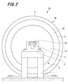
- FIG. 2 is a side view showing a hoisting machine.
- the device shown in FIG. 1 is a hoisting machine used for the elevator 100 (see FIG. 4).
- the hoisting machine 10 has a pair of pedestals 1, 1 and a spindle 3, and a hoisting machine unit 50.
- the hoisting machine 10 includes a plurality of first stators 14A constituting the first motor 7, a plurality of first rotors 15A, and a plurality of second stators 14B constituting the second motor 8.
- the second rotor 15B and the like.
- the pair of pedestals 1 and 1 are arranged so as to face one end and the other end of the spindle 3 in the axial direction. Further, the gantry 1 is provided with a support portion 4 for supporting the main shaft 3.
- the support portion 4 supports the axial end portion of the spindle 3. Further, the support portion 4 is provided with a key plate 4a for fixing the main shaft 3. The rotation and axial movement of the spindle 3 are restricted by the key plate 4a.
- a hoisting machine unit 50 is detachably attached to the spindle 3 via a fixing member 17.
- the hoisting machine unit 50 includes a housing 2, a sheave 5, and a rotating body 6.
- the housing 2 has a first support member 11, a second support member 12, and a shaft portion 13.
- the first support member 11 and the shaft portion 13 are integrally formed.
- the shaft portion 13 is formed in a substantially cylindrical shape.
- the spindle 3 is inserted into the tubular hole 13a of the shaft portion 13.
- a mounting recess 22 is formed at one end of the shaft portion 13 in the axial direction, and a second support member 12 is fixed to the other end of the shaft portion 13 in the axial direction via a fixing bolt 16.
- the mounting recess 22 is a recess formed in a substantially cylindrical shape, and one end side of the main shaft 3 in the axial direction is open.
- the outer diameter of the mounting recess 22 is formed to be larger than the outer diameter of the shaft portion 13.
- the mounting recess 22 surrounds the outer peripheral surface at one end of the spindle 3 in the axial direction.
- a fixing member 17 is interposed between the mounting recess 22 and one end of the spindle 3 in the axial direction.
- the fixing member 17 is composed of two cylindrical portions 17a having a wedge-shaped cross section and a fastening bolt 17b. Then, by tightening the fastening bolt 17b, the outer peripheral surface of the cylindrical portion 17a is pressed against the inner surface 22a of the mounting recess 22, and the inner peripheral surface of the cylindrical portion 17a is pressed against the outer peripheral surface of the main shaft 3. As a result, the housing 2 and the spindle 3 are firmly connected via the fixing member 17, and rotation and axial movement of the housing 2 are restricted.
- the fixing member 17 is not limited to the above-mentioned configuration, and various other fixing members are applied.
- first support member 11 is continuously formed on the outer peripheral surfaces of the shaft portion 13 and the mounting recess 22.
- the first support member 11 has a side surface portion 23 and a first stator support portion 24.
- the side surface portion 23 extends substantially vertically from one end in the axial direction of the mounting recess 22 toward the radial direction. Further, the side surface portion 23 is formed in a substantially disk shape.
- a first stator support portion 24 is formed at an end portion of the side surface portion 23 opposite to the mounting recess 22.
- the first stator support portion 24 has a mounting portion 25 and a side wall portion 26.
- the mounting portion 25 is formed in a substantially cylindrical shape, and projects substantially vertically from the side surface portion 23 toward the other end portion of the main shaft 3 in the axial direction.
- the mounting portion 25 is arranged concentrically with the shaft portion 13 and the mounting recess 22.
- a plurality of first stators 14A are fixed to the outer peripheral surface 25a of the mounting portion 25.
- the plurality of first stators 14A are composed of an iron core and a stator coil wound around the iron core. Then, the plurality of first stators 14A are arranged in an annular shape along the circumferential direction of the mounting portion 25.
- the side wall portion 26 projects substantially perpendicularly from one end in the axial direction on the outer peripheral surface 25a of the mounting portion 25 toward the outside in the radial direction. Further, the side wall portion 26 is formed in a substantially disk shape and covers one end portion in the axial direction of the plurality of first stators 14A fixed to the mounting portion 25.
- the second support member 12 has a side surface portion 33 and a second stator support portion 34.
- the side surface portion 33 is formed in a substantially disk shape.
- a circular opening 33a is formed at the center of the side surface portion 33 in the radial direction. The other end of the spindle 3 in the axial direction and the other end of the shaft 13 in the axial direction are inserted into the opening 33a.
- the side surface portion 33 extends outward in the radial direction from the outer peripheral surface 13b of the shaft portion 13.
- the side surface portion 33 of the second support member 12 faces the side surface portion 23 of the first support member 11 at a distance. Then, a storage space is formed by the side surface portion 23 of the first support member 11 and the side surface portion 33 of the second support member 12. In this storage space, the bearing housing 41 of the rotating body 6 described later is arranged.
- a second stator support portion 34 is formed at the end portion of the side surface portion 33 opposite to the shaft portion 13.
- the second stator support portion 34 has a mounting portion 35 and a side wall portion 36.
- the mounting portion 35 is formed in a substantially cylindrical shape, and projects substantially vertically from the side surface portion 33 toward one end portion of the main shaft 3 in the axial direction.
- the mounting portion 35 is arranged concentrically with the shaft portion 13.
- a plurality of second stators 14B are fixed to the outer peripheral surface 35a of the mounting portion 35.
- the plurality of second stators 14B are composed of an iron core and a stator coil wound around the iron core. Then, the plurality of second stators 14B are arranged in an annular shape along the circumferential direction of the mounting portion 35.
- the side wall portion 36 projects substantially vertically outward from one end in the axial direction on the outer peripheral surface 35a of the mounting portion 35 toward the outside in the radial direction.
- the side wall portion 36 is formed in a substantially disk shape and covers one end portion in the axial direction of the plurality of second stators 14B fixed to the mounting portion 35. Further, the side wall portion 36 of the second support member 12 faces the side wall portion 26 of the first support member 11 at a distance.
- a rotating body 6 is arranged between the side wall portion 36 of the second support member 12 and the side wall portion 26 of the first support member 11.
- the rotating body 6 is formed in a substantially disk shape.
- the rotating body 6 has a bearing housing 41, a connecting portion 42, and a rotor supporting portion 43.
- the bearing housing 41 is formed at the center of the rotating body 6 in the radial direction.
- the bearing housing 41 is formed in a cylindrical shape, and a support hole 41a penetrating from one end to the other end in the axial direction is formed.
- a bearing 46 is provided on the inner wall of the support hole 41a. Further, the bearing housing 41 is arranged in a storage space formed between the side surface portion 23 of the first support member 11 and the side surface portion 33 of the second support member 12.
- the rotating body 6 is rotatably supported on the outer peripheral surface 13b of the shaft portion 13 of the housing 2 via the bearing 46.
- the connecting portion 42 projects substantially vertically from the outer peripheral surface of the bearing housing 41.
- the connecting portion 42 is formed in a substantially disk shape.
- the connecting portion 42 is arranged between the first support member 11 and the second support member 12.
- the end portion of the connecting portion 42 opposite to the bearing housing 41, that is, the outer end portion in the radial direction is fixed to the plurality of first stators 14A and the second support member 12 fixed to the first support member 11. It is arranged radially outside the plurality of second stators 14B.
- the radial outer end of the connecting portion 42 is arranged between the side wall portion 26 of the first support member 11 and the side wall portion 36 of the second support member 12.
- a rotor support portion 43 is provided at the outer end portion of the connecting portion 42 in the radial direction.
- the rotor support portion 43 is formed in a substantially cylindrical shape, and protrudes from the end portion of the connecting portion 42 toward both sides in the axial direction. Further, the rotor support portion 43 is arranged on the first support member 11 and the second support member 12 on the outer side in the radial direction from the mounting portions 25 and 35.
- the inner wall surface 43a of the rotor support portion 43 faces the outer peripheral surface 25a of the mounting portion 25 of the first support member 11 and the outer peripheral surface 35a of the mounting portion 35 of the second support member 12.
- a plurality of first rotors 15A and a plurality of second rotors 15B are fixed to the inner wall surface 43a of the rotor support portion 43.
- the plurality of first rotors 15A are arranged on one end side in the axial direction of the rotor support portion 43 and face the plurality of first stators 14A.
- the plurality of second rotors 15B are arranged on the other end side in the axial direction of the rotor support portion 43 and face the plurality of second stators 14B.
- the first rotor 15A and the second rotor 15B are composed of magnets.
- the plurality of first rotors 15A and the plurality of second rotors 15B are fixed at predetermined intervals along the circumferential direction of the rotor support portion 43, respectively. Further, in the plurality of first rotors 15A and the plurality of second rotors 15B, north poles and south poles are alternately arranged along the circumferential direction of the rotor support portion 43, respectively.
- the outer peripheral surface 43b of the rotor support portion 43 is arranged outside the housing 2 in the radial direction.
- a sheave 5 is fixed to the outer peripheral surface 43b of the rotor support portion 43.
- the sheave 5 is formed in an annular shape.
- a rope connected to an elevating body such as a car or a counterweight in an elevator is wound around the sheave 5. Then, when the hoisting machine 10 is driven, the sheave 5 rotates, and the rope wound around the sheave 5 moves.
- the rotating body 6 to which the rotors 15A and 15B are fixed is rotatably supported by the housing 2.
- the axial length of the spindle 3 that supports the load applied to the hoisting machine 10 can be shortened, and the entire hoisting machine 10 can be miniaturized.
- two motors a first motor 7 and a second motor 8, can be configured in one hoisting machine 10, and a thin and large torque can be obtained.
- FIG. 3 is a cross-sectional view showing a disassembled state of the hoisting machine 10.
- first stators 14A are fixed to the attachment portion 25 of the first support member 11, and a plurality of second stators 14B are fixed to the attachment portion 35 of the second support member 12. Further, a plurality of first rotors 15A and a plurality of second rotors 15B are fixed to the rotor support portion 43 of the rotating body 6, and the bearing 46 is attached to the bearing housing 41. Further, the sheave 5 is fixed to the rotor support portion 43 of the rotating body 6.
- the rotating body 6 is rotatably attached to the shaft portion 13.
- the plurality of first stators 14A and the plurality of first rotors 15A face each other to form the first motor 7.
- the second support member 12 is fixed to the other end of the shaft portion 13 in the axial direction by the fixing bolt 16.
- the plurality of second stators 14B and the plurality of second rotors 15B face each other to form the second motor 8.
- the hoisting machine unit 50 in which the housing 2 to which the stators 14A and 14B are fixed and the rotating body 6 to which the rotors 15A and 15B are fixed can be assembled can be assembled.
- the spindle 3 is inserted into the tubular hole 13a of the shaft portion 13.
- the cylindrical portion 17a of the fixing member 17 is inserted between the mounting recess 22 of the first support member 11 and the main shaft 3, and the fastening bolt 17b is tightened.
- the outer peripheral surface of the cylindrical portion 17a is in pressure contact with the inner surface 22a of the mounting recess 22, and the inner peripheral surface of the cylindrical portion 17a is in pressure contact with the outer peripheral surface of the main shaft 3.
- the housing 2 and the spindle 3 are firmly connected via the fixing member 17. Then, by attaching the spindle 3 to the support portion 4 of the gantry 1, the assembly work of the hoisting machine 10 is completed.
- the spindle 3 can be attached / detached while the stators 14A and 14B and the rotors 15A and 15B face each other, and the hoisting machine 10 can be easily assembled.
- first support member 11 and the second support member 12 in the housing 2 which is a fixed element are arranged on both sides in the axial direction of the rotating body 6 which is a rotating element of the hoisting machine unit 50.
- the rotational operation of the rotating body 6 is not affected.
- the hoisting machine unit 50 can be easily conveyed with the spindle 3 removed from the hoisting machine unit 50.
- FIG. 4 is a schematic configuration diagram showing an elevator.
- the elevator 100 includes a car 110 that goes up and down in the hoistway 150, a hoisting machine 10, a balance weight 130, and a main rope 140.
- One end of the main rope 140 is connected to a car 110 showing an example of an elevating body, and the other end of the main rope 140 is connected to a counterweight 130 showing another example of the elevating body.
- the main rope 140 is wound around the sheave 5 (see FIG. 1) of the hoisting machine 10.
- the hoisting machine 10 is driven, the main rope 140 moves, and the car 110 and the balance weight 130 move up and down in the hoistway 150.
- the hoisting machine 10 is installed in the machine room 151 provided at the top of the hoistway 150. Further, in the machine room 151, a plurality of (two in this example) brake mechanisms 160 for braking the rotation of the sheave 5 in the hoisting machine 10 and a speed sensor 170 for detecting the rotation speed of the sheave 5 are arranged. Has been done.
- the brake mechanisms 160, 160 and the speed sensor 170 are arranged on the outer peripheral portion of the sheave 5 in the hoisting machine 10. Further, in the example shown in FIG. 4, one of the two brake mechanisms 160 and 160 is arranged on one side of the gantry 1, and the other brake mechanism 160 is arranged on the other side of the gantry 1. There is. Further, the speed sensor 170 is arranged at the lower end portion in the vertical direction on the outer peripheral portion of the sheave 5. Then, the speed sensor 170 comes into contact with the outer peripheral portion of the sheave 5 and detects the rotational speed of the sheave 5.
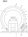
- FIG. 5 is a side view showing another example of the installation position of the brake mechanism. As shown in FIG. 5, the two brake mechanisms 160 and 160 may be arranged together on one side of the gantry 1. Further, in the example shown in FIG. 5, the speed sensor 170 contacts the rotating body 6 in the hoisting machine 10 and detects the rotating speed of the sheave 5 from the rotating speed of the rotating body 6.
- the brake mechanism 160 and the speed sensor 170 can be installed at arbitrary positions on the outer peripheral portions of the sheave 5 and the rotating body 6.
- the brake mechanism 160 and the speed sensor 170 are preferably arranged below the main shaft 3 of the hoisting machine 10 in the vertical direction.
- FIG. 6 and 7 show the brake mechanism 160, FIG. 6 shows the state before the brake mechanism operates, and FIG. 7 shows the state in which the brake mechanism operates.
- the brake mechanism 160 has an electromagnetic core 161 provided with an electromagnetic coil, an amateur 162, and a pair of brake levers 163A and 163B.
- the electromagnetic core 161 and the amateur 162 are arranged on the outer side in the radial direction from the sheave 5.
- the magnetic attraction surface of the electromagnetic core 161 faces the axial direction of the sheave 5.
- the amateur 162 is arranged so as to face the magnetic attraction surface of the electromagnetic core 161.
- the amateur 162 is urged in a direction away from the electromagnetic core 161 by an urging member (not shown).
- the first brake lever 163A is connected to the electromagnetic core 161 and the second brake lever 163B is connected to the amateur 162.
- One end of the first brake lever 163A is connected to a surface of the electromagnetic core 161 opposite to the magnetic attraction surface.
- One end of the second brake lever 163B is connected to a surface of the amateur 162 opposite to the surface facing the magnetic attraction surface.
- the first brake lever 163A protrudes from the electromagnetic core 161 toward the sheave 5, and the second brake lever 163B protrudes from the amateur 162 toward the sheave 5.
- the other end of the first brake lever 163A faces the first braking surface 5a, which is a side surface portion of the sheave 5 on one end side in the axial direction.
- the other end of the second brake lever 163B faces the second braking surface 5b, which is a side surface portion of the sheave 5 on the other end side in the axial direction.
- brake shoes 164 are provided at the other ends of the first brake lever 163A and the second brake lever 163B at positions facing the side surface of the sheave 5. Further, the first brake lever 163A and the second brake lever 163B are rotatably supported by the rotation shaft 165, respectively. The rotating shaft 165 is provided at an intermediate portion between the first brake lever 163A and the second brake lever 163B.
- the electromagnetic coil of the electromagnetic core 161 is energized, and the amateur 162 is attracted to the magnetic attraction surface of the electromagnetic core 161 against the urging force of the urging member. Further, the first brake lever 163A and the second brake lever 163B rotate about the rotation shaft 165. Then, the two brake shoes 164 and 164 are separated from the first braking surface 5a and the second braking surface 5b of the sheave 5.
- the energization of the electromagnetic coil is stopped and the magnetism of the electromagnetic core 161 is erased. Therefore, as shown in FIG. 7, the electromagnetic core 161 and the amateur 162 are urged by the urging member and move in a direction away from each other. Further, the first brake lever 163A and the second brake lever 163B rotate about the rotation shaft 165. Then, the two brake shoes 164 and 164 are pressed against the first braking surface 5a and the second braking surface 5b of the sheave 5. That is, the sheave 5 is sandwiched by the first brake lever 163A and the second brake lever 163B. As a result, the rotational operation of the sheave 5 and the rotating body 6 of the hoisting machine 10 is braked.
- the brake mechanism is not limited to the above-mentioned configuration, and various other configurations can be applied.
- FIG. 8 is a schematic configuration diagram showing an elevator according to the second embodiment
- FIG. 9 is a plan view showing the elevator according to the second embodiment.
- the elevator according to the second embodiment is a so-called multi-car elevator in which a car, which is a plurality of elevating bodies, moves in the same hoistway.
- the parts common to the elevator 100 and the hoisting machine 10 according to the first embodiment are designated by the same reference numerals, and duplicate description will be omitted.
- the elevator 200 includes a plurality of pairs (3 pairs in this example) of the car 210A, 210B, 210C indicating an elevating body, a first hoisting machine 220, and a second hoisting machine. It includes a machine 230, a first lower pulley 240, and a second lower pulley 250. Further, the elevator 200 includes three first main ropes 260A, 260B, 260C and second main ropes 270A, 270B, and 270C according to the pair of the car 210.
- first lower pulley 240 and the second lower pulley 250 are also provided in three sets according to the pair of the car 210.
- the first hoisting machine 220 and the second hoisting machine 230 have three hoisting machine units 50A, 50B, and 50C, respectively, corresponding to the number of the first main rope 260 and the second main rope 270. ..
- the first hoisting machine 220 and the second hoisting machine 230 are arranged at the top of the hoistway 280, and the first lower pulley 240 and the second lower pulley 250 are arranged at the lower part of the hoistway 280. Further, the first hoisting machine 220 and the first lower pulley 240 face each other in the elevating direction, and the second hoisting machine 230 and the second lower pulley 250 face each other in the elevating direction.
- the first main rope 260A, 260B, 260C and the second main rope 270A, 270B, 270C are formed in an endless shape in which both ends are connected.
- the first main rope 260 is stretched on the first hoisting machine 220 and the first lower pulley 240, and the second main rope 270 is stretched on the second hoisting machine 230 and the second lower pulley 250. There is.
- the car 210A is connected to the first main rope 260A and the second main rope 270A
- the car 210B is connected to the first main rope 260B and the second main rope 270B
- the car 210C is connected to the first main rope 260C and the second main rope 270C.
- the first hoisting machine 220 and the second hoisting machine 230 By driving the first hoisting machine 220 and the second hoisting machine 230, the first main rope 260A, 260B, 260C and the second main rope 270A, 270B, 270C move, and three pairs of car 210A, 210B. , 210C move in the hoistway 280. Further, when the three pairs of cars 210A, 210B and 210C pass through the first hoisting machine 220, the second hoisting machine 230, the first lower pulley 240 and the second lower pulley 250, their moving directions are reversed. To do. As a result, the three pairs of cars 210A, 210B, and 210C move on the hoistway 280.
- FIG. 10 is a cross-sectional view showing the first hoisting machine 220.
- the hoisting machine 220 has a pair of mounts 221 and 221, a spindle 223, and three hoisting machine units 50A, 50B, and 50C.
- the three hoisting machine units 50A, 50B, and 50C each have the same configuration as the hoisting machine unit 50 according to the first embodiment.
- the pair of pedestals 221 and 221 are arranged so as to face one end and the other end of the spindle 223 in the axial direction.
- the gantry 1 is provided with a support portion 224 for supporting the main shaft 223.
- the support portion 224 supports the axial end portion of the spindle 223.
- the support portion 224 is provided with a key plate 224a for fixing the main shaft 223. The rotation and axial movement of the spindle 223 are restricted by the key plate 224a.
- the first hoisting machine unit 50A is arranged on one end side of the spindle 223 in the axial direction
- the third hoisting machine unit 50C is arranged on the other end side of the spindle 223 in the axial direction.
- the second hoisting machine unit 50B is arranged between the first hoisting machine unit 50A and the third hoisting machine unit 50C.
- the tubular holes 13a of the shaft portion 13 of each hoisting machine unit 50A, 50B, 50C are parallel to the axial direction of the spindle 223. It communicates linearly with.
- the spindle 223 is inserted into the cylinder hole 13a of the shaft portion 13 of the three hoisting machine units 50A, 50B, and 50C. Then, the housing 2 of the hoisting machine units 50A, 50B, 50C is fixed to one main shaft 223 common to the fixing members 17A, 17B, 17C.
- the rotating body 6 which is a rotating element is sandwiched between the first support member 11 and the second support member 12 in the housing 2 which is a fixed element. Since both sides of the hoisting machine unit 50 in the axial direction are the first support member 11 and the second support member 12 which are fixing elements, other members are arranged on both sides of the hoisting machine unit 50 in the axial direction. However, it does not affect the rotational operation of the rotating body 6.
- the first hoisting machine unit 50A and the second hoisting machine unit 50B can be arranged close to each other, and the second hoisting machine unit 50B and the third hoisting machine unit 50C can be arranged close to each other. Can be done.
- the axial length of the spindle 223 penetrating the three hoisting machine units 50A, 50B, and 50C can be shortened, and the entire hoisting machine 220 can be miniaturized.
- the three hoisting machine units 50A, 50B, and 50C can be driven independently.
- the three pairs of cars 210A, 210B, and 210C can be moved up and down independently.
- the number of hoisting machine units 50 is not limited to three, but is appropriately set according to the number of car 210s.
- the elevator 200 and the hoisting machine 220 having such a configuration can also obtain the same effects as the elevator 100 and the hoisting machine 10 according to the first embodiment described above.
- FIG. 11 is a cross-sectional view showing the hoisting machine according to the third embodiment.
- a plurality of hoisting machine units are arranged, and a plurality of hoisting machine units are further arranged. It is a combination.
- the parts common to the hoisting machine 10 according to the first embodiment and the hoisting machine 220 according to the second embodiment are designated by the same reference numerals, and duplicate description will be omitted.
- the hoisting machine 310 has a pair of mounts 221 and 221, a spindle 223, and three hoisting machine units 50A, 50B, and 50C.
- the three hoisting machine units 50A, 50B, and 50C each have the same configuration as the hoisting machine unit 50 according to the first embodiment.
- the first hoisting machine unit 50A is arranged on one end side of the spindle 223 in the axial direction
- the third hoisting machine unit 50C is arranged on the other end side of the spindle 223 in the axial direction.
- the second hoisting machine unit 50B is arranged between the first hoisting machine unit 50A and the third hoisting machine unit 50C. Then, the main shaft 223 is inserted into the tubular hole 13a of the shaft portion 13 of the three hoisting machine units 50A, 50B, 50C, and the housing 2 of the hoisting machine units 50A, 50B, 50C has the fixing members 17A, 17B. , 17C fixed to the spindle 223.
- the second support member 12 of the first hoisting machine unit 50A and the first support member 11 of the second hoisting machine unit 50B are connected by the housing connecting member 311. Then, the rotating body 6 of the first hoisting machine unit 50A and the rotating body 6 of the second hoisting machine unit 50B are connected by the rotating body coupling member 312 at the rotor support portion 43 exposed from the housing 2. Has been done.
- the second support member 12 of the second hoisting machine unit 50B and the first support member 11 of the third hoisting machine unit 50C are connected by the housing connecting member 313.
- the rotating body 6 of the second hoisting machine unit 50B and the rotating body 6 of the third hoisting machine unit 50C are connected by the rotating body coupling member 314 at the rotor support portion 43 exposed from the housing 2. Has been done. As a result, the rotating bodies 6 of the three hoisting machine units 50A, 50B, and 50C rotate together.
- the torque of the hoisting machine 310 can be easily increased.
- the number of hoisting machine units 50 is not limited to three, and is appropriately set according to the required torque, the load capacity of the elevating body, and the load.
- the hoisting machine 310 having such a configuration can also obtain the same operation and effect as the hoisting machine 10 according to the first embodiment described above.
- FIG. 12 is a cross-sectional view showing the hoisting machine according to the fourth embodiment.
- the hoisting machine 410 according to the fourth embodiment is different from the hoisting machine 310 according to the third embodiment in that the configuration of the hoisting machine unit is changed and a braking disc is provided. It is a thing.
- the parts common to the hoisting machine 10 according to the first embodiment and the hoisting machine 310 according to the third embodiment are designated by the same reference numerals, and duplicate description will be omitted.
- the hoisting machine 410 has a pair of mounts 221 and 221, a spindle 223, three hoisting machine units 60A, 60B, 60C, and a braking disc 412.
- the hoisting machine units 60A, 60B, and 60C each have a housing 62 and a rotating body 66. Then, each housing 62 and the rotating body 66 are connected by a coupling member 311, 312, 313, 314.
- the housing 62 has a first support member 71, a second support member 72, and a shaft portion 73. Since the configuration of the second support member 72 is the same as that of the second support member 12 according to the first embodiment, the description thereof will be omitted.
- the first support member 71 is fixed to one end of the shaft portion 73 in the axial direction via a fixing bolt 18. That is, in the hoisting machine unit 60 according to the fourth embodiment, the shaft portion 73 and the first support member 71 are configured as separate members. Since the other configurations are the same as those of the shaft portion 13 and the first support member 11 according to the first embodiment, the description thereof will be omitted.
- a sheave 75 is integrally formed with the rotor support portion 74 of the rotating body 66 in the first hoisting machine unit 60A and the second hoisting machine unit 60B.
- a sheave is not formed on the rotor support portion 74 of the rotating body 66 in the third winding machine unit 60C. In this way, the width of the sheave and the number of grooves can be freely combined according to the required torque and the number of main ropes.
- a braking disc 412 is fixed to the rotor support portion 74 of the third winding machine unit 60C by a mounting bolt 19.
- the braking disc 412 is formed in a substantially disk shape. Then, the braking disc 412 is sandwiched by a brake mechanism (not shown), so that the rotational operation of the rotating bodies 66 of the three hoisting machine units 60A, 60B, and 60C is braked.
- the hoisting machine 410 having such a configuration also obtains the same effects as those of the hoisting machine 10 according to the first embodiment and the hoisting machine 310 according to the third embodiment described above. Can be done.
- FIG. 13 is a cross-sectional view showing the hoisting machine according to the fifth embodiment.
- the hoisting machine 510 according to the fifth embodiment is different from the hoisting machine 10 according to the first embodiment in the installation position of the housing and the sheave. Therefore, the same reference numerals are given to the parts common to the hoisting machine 10 according to the first embodiment, and duplicate description will be omitted.
- the hoisting machine 510 has a pair of pedestals 1, 1 and a spindle 3, and a hoisting machine unit 550. Further, the hoisting machine 510 has a plurality of stators 14 and a plurality of rotors 15. The hoisting machine unit 550 is attached to the spindle 3 by a fixing member 17.
- the hoisting machine unit 550 includes a housing 502, a sheave 505, a rotating body 506, and a braking disc 512.
- the housing 502 has a support member 511 and a shaft portion 513.
- the support member 511 and the shaft portion 513 are integrally formed.
- a plurality of stators 14 are fixed to the support member 511. Since the support member 511 and the shaft portion 513 have the same configuration as the first support member 11 and the shaft portion 13 according to the first embodiment, the description thereof will be omitted. That is, the housing 502 according to the fifth embodiment has a configuration in which the second support member 12 is removed from the housing 2 according to the first embodiment.
- a rotating body 506 is rotatably supported on the outer peripheral surface 513b of the shaft portion 513 via a bearing 46.
- the rotating body 506 includes a bearing housing 541 provided with a bearing 46, a connecting portion 542, and a rotor supporting portion 543. Since the structure of the bearing housing 541 has the same structure as that of the bearing housing 41 according to the first embodiment, the description thereof will be omitted.
- the connecting portion 542 projects substantially vertically from the outer peripheral surface of the bearing housing 541.
- the connecting portion 542 is formed in a substantially disk shape.
- a rotor support portion 543 is provided at the outer end portion of the connecting portion 542 in the radial direction.
- the rotor support portion 543 is formed in a substantially cylindrical shape, and protrudes from the end portion of the connecting portion 542 toward one end portion in the axial direction.
- a plurality of rotors 15 are fixed to the inner wall surface 543a of the rotor support portion 543. Then, the plurality of rotors 15 face the plurality of stators 14 fixed to the support member 511.
- a sheave 505 is arranged on one surface of the connecting portion 542 on the other end side of the main shaft 3 in the axial direction. Further, a disc-shaped braking disc 512 is arranged at an end of the sheave 505 opposite to the connecting portion 542. The sheave 505 and the braking disc 512 are fixed to the connecting portion 542 by mounting bolts 518.
- the hoisting machine unit 550 can be detachably attached to the spindle 3, and assembly and transfer work can be easily performed.
- the hoisting machine 510 having such a configuration can also obtain the same operation and effect as the hoisting machine 10 according to the first embodiment described above.
Landscapes
- Engineering & Computer Science (AREA)
- Civil Engineering (AREA)
- Mechanical Engineering (AREA)
- Structural Engineering (AREA)
- Cage And Drive Apparatuses For Elevators (AREA)
Priority Applications (2)
| Application Number | Priority Date | Filing Date | Title |
|---|---|---|---|
| JP2021565161A JP7261320B2 (ja) | 2019-12-16 | 2019-12-16 | 巻上機及びエレベーター |
| PCT/JP2019/049142 WO2021124389A1 (ja) | 2019-12-16 | 2019-12-16 | 巻上機及びエレベーター |
Applications Claiming Priority (1)
| Application Number | Priority Date | Filing Date | Title |
|---|---|---|---|
| PCT/JP2019/049142 WO2021124389A1 (ja) | 2019-12-16 | 2019-12-16 | 巻上機及びエレベーター |
Publications (1)
| Publication Number | Publication Date |
|---|---|
| WO2021124389A1 true WO2021124389A1 (ja) | 2021-06-24 |
Family
ID=76478542
Family Applications (1)
| Application Number | Title | Priority Date | Filing Date |
|---|---|---|---|
| PCT/JP2019/049142 Ceased WO2021124389A1 (ja) | 2019-12-16 | 2019-12-16 | 巻上機及びエレベーター |
Country Status (2)
| Country | Link |
|---|---|
| JP (1) | JP7261320B2 (https=) |
| WO (1) | WO2021124389A1 (https=) |
Cited By (1)
| Publication number | Priority date | Publication date | Assignee | Title |
|---|---|---|---|---|
| CN115783953A (zh) * | 2022-12-23 | 2023-03-14 | 浙江恒达富士电梯工程有限公司 | 多圈缠绕式的曳引轮结构 |
Citations (8)
| Publication number | Priority date | Publication date | Assignee | Title |
|---|---|---|---|---|
| JPH0710434A (ja) * | 1993-06-28 | 1995-01-13 | Kone Oy | トラクションシーブエレベータ |
| JPH0840676A (ja) * | 1994-06-23 | 1996-02-13 | Kone Oy | エレベータ機械装置 |
| JP2000153973A (ja) * | 1998-11-19 | 2000-06-06 | Nippon Elevator Mfg Co Ltd | エレベ−タ装置 |
| WO2004035450A1 (ja) * | 2002-10-18 | 2004-04-29 | Mitsubishi Denki Kabushiki Kaisha | エレベータの駆動装置 |
| JP2006027803A (ja) * | 2004-07-15 | 2006-02-02 | Mitsubishi Electric Corp | エレベータ用巻上機 |
| WO2006033152A1 (ja) * | 2004-09-24 | 2006-03-30 | Mitsubishi Denki Kabushiki Kaisha | エレベータ装置 |
| JP2009528815A (ja) * | 2006-04-28 | 2009-08-06 | ジェゼック,ジョルジオ | 少数の回転を有する、特にリフト装置を駆動するための電気モータ |
| CN205602987U (zh) * | 2016-04-26 | 2016-09-28 | 江门市蒙德电气股份有限公司 | 一种永磁同步曳引机 |
-
2019
- 2019-12-16 JP JP2021565161A patent/JP7261320B2/ja active Active
- 2019-12-16 WO PCT/JP2019/049142 patent/WO2021124389A1/ja not_active Ceased
Patent Citations (8)
| Publication number | Priority date | Publication date | Assignee | Title |
|---|---|---|---|---|
| JPH0710434A (ja) * | 1993-06-28 | 1995-01-13 | Kone Oy | トラクションシーブエレベータ |
| JPH0840676A (ja) * | 1994-06-23 | 1996-02-13 | Kone Oy | エレベータ機械装置 |
| JP2000153973A (ja) * | 1998-11-19 | 2000-06-06 | Nippon Elevator Mfg Co Ltd | エレベ−タ装置 |
| WO2004035450A1 (ja) * | 2002-10-18 | 2004-04-29 | Mitsubishi Denki Kabushiki Kaisha | エレベータの駆動装置 |
| JP2006027803A (ja) * | 2004-07-15 | 2006-02-02 | Mitsubishi Electric Corp | エレベータ用巻上機 |
| WO2006033152A1 (ja) * | 2004-09-24 | 2006-03-30 | Mitsubishi Denki Kabushiki Kaisha | エレベータ装置 |
| JP2009528815A (ja) * | 2006-04-28 | 2009-08-06 | ジェゼック,ジョルジオ | 少数の回転を有する、特にリフト装置を駆動するための電気モータ |
| CN205602987U (zh) * | 2016-04-26 | 2016-09-28 | 江门市蒙德电气股份有限公司 | 一种永磁同步曳引机 |
Cited By (1)
| Publication number | Priority date | Publication date | Assignee | Title |
|---|---|---|---|---|
| CN115783953A (zh) * | 2022-12-23 | 2023-03-14 | 浙江恒达富士电梯工程有限公司 | 多圈缠绕式的曳引轮结构 |
Also Published As
| Publication number | Publication date |
|---|---|
| JP7261320B2 (ja) | 2023-04-19 |
| JPWO2021124389A1 (https=) | 2021-06-24 |
Similar Documents
| Publication | Publication Date | Title |
|---|---|---|
| JP2000016727A (ja) | エレベーター装置 | |
| JP2016037336A (ja) | エレベータ装置およびエレベータ装置用巻上機 | |
| JP2004338915A (ja) | エレベータ用巻上機 | |
| JP5048802B2 (ja) | エレベータ用薄型巻上機、及びエレベータ装置 | |
| JP5255785B2 (ja) | エレベータ用巻上機 | |
| WO2021124389A1 (ja) | 巻上機及びエレベーター | |
| JP4476809B2 (ja) | エレベータの駆動装置 | |
| CN100369798C (zh) | 电梯用薄形卷扬机 | |
| JP4499496B2 (ja) | エレベータ用巻上機 | |
| JP5032723B2 (ja) | エレベータ用巻上機 | |
| JP3617771B2 (ja) | エレベータ用巻上機 | |
| JP2003201082A (ja) | エレベータ用巻上機 | |
| KR100784923B1 (ko) | 엘리베이터 권상기 | |
| CN101688577A (zh) | 电梯的曳引机 | |
| JP2004299910A (ja) | エレベータ装置 | |
| JP2002154773A (ja) | エレベータ装置および巻上機 | |
| JP2016182015A (ja) | 埋込磁石型電動機、及びこの埋込磁石型電動機を用いたエレベータ用巻上機、及びこのエレベータ用巻上機を用いたエレベータ、及びこの埋込磁石型電動機を用いたインホイールモータ装置 | |
| KR100824493B1 (ko) | 엘리베이터용 권상기 | |
| JP2005126166A (ja) | エレベータの改造作業方法及びエレベータ | |
| JPH11157766A (ja) | 巻上機 | |
| KR20070105150A (ko) | 엘리베이터 권상기 | |
| JPH11325128A (ja) | 電磁ブレーキおよびエレベータ装置の巻上機 | |
| KR200421632Y1 (ko) | 엘리베이터 권상기 | |
| KR20010056690A (ko) | 엘리베이터용 권상기 | |
| WO2026053836A1 (ja) | 巻上機 |
Legal Events
| Date | Code | Title | Description |
|---|---|---|---|
| 121 | Ep: the epo has been informed by wipo that ep was designated in this application |
Ref document number: 19956923 Country of ref document: EP Kind code of ref document: A1 |
|
| ENP | Entry into the national phase |
Ref document number: 2021565161 Country of ref document: JP Kind code of ref document: A |
|
| NENP | Non-entry into the national phase |
Ref country code: DE |
|
| 122 | Ep: pct application non-entry in european phase |
Ref document number: 19956923 Country of ref document: EP Kind code of ref document: A1 |