WO2021111602A1 - ブロー成形不良検知装置、ブロー成形不良検知方法、プログラム - Google Patents
ブロー成形不良検知装置、ブロー成形不良検知方法、プログラム Download PDFInfo
- Publication number
- WO2021111602A1 WO2021111602A1 PCT/JP2019/047681 JP2019047681W WO2021111602A1 WO 2021111602 A1 WO2021111602 A1 WO 2021111602A1 JP 2019047681 W JP2019047681 W JP 2019047681W WO 2021111602 A1 WO2021111602 A1 WO 2021111602A1
- Authority
- WO
- WIPO (PCT)
- Prior art keywords
- frequency
- blow molding
- parison
- defect detection
- molding defect
- Prior art date
- Legal status (The legal status is an assumption and is not a legal conclusion. Google has not performed a legal analysis and makes no representation as to the accuracy of the status listed.)
- Ceased
Links
Images









Classifications
-
- G—PHYSICS
- G01—MEASURING; TESTING
- G01M—TESTING STATIC OR DYNAMIC BALANCE OF MACHINES OR STRUCTURES; TESTING OF STRUCTURES OR APPARATUS, NOT OTHERWISE PROVIDED FOR
- G01M3/00—Investigating fluid-tightness of structures
- G01M3/02—Investigating fluid-tightness of structures by using fluid or vacuum
- G01M3/04—Investigating fluid-tightness of structures by using fluid or vacuum by detecting the presence of fluid at the leakage point
- G01M3/24—Investigating fluid-tightness of structures by using fluid or vacuum by detecting the presence of fluid at the leakage point using infrasonic, sonic or ultrasonic vibrations
Definitions
- the present invention relates to a blow molding defect detection device for detecting molding defects (perforations) in a blow molded product, a blow molding defect detection method, and a program.
- thermoplastic resin thermoplastic resin
- Fig. 1 blow molding that solidifies and molds
- Patent Document 1 a method of detecting the occurrence of holes by using a change in the air pressure of compressed air as a clue
- Patent Document 2 a method of detecting the presence of holes in a molded product by using image detection technology
- Patent Document 1 For example, in the method using the change in air pressure of compressed air as a clue (Patent Document 1), the change in air pressure is very small in a very small hole having a hole diameter of several mm or less, and it is difficult to detect the occurrence of the hole. On the other hand, even in the method using an image (Patent Document 2), the existence of holes hidden in the shadow of unevenness such as the design of a product which is a molded product may not be detected.
- an object of the present invention is to provide a blow molding defect detection device capable of detecting minute holes generated during molding of a hollow product by blow molding.
- the blow molding defect detection device of the present invention includes a recording unit, a signal processing unit, and a determination unit.
- the recording section records the blowing sound generated when compressed air is blown into the parison.
- the signal processing unit weights the cepstrum coefficient of the blown sound signal using a preset window function, and outputs the processed signal obtained by converting the weighted cepstrum coefficient into the frequency domain.
- the determination unit determines that the parison has a hole when the sum of energies of a frequency higher than the preset boundary frequency of the processed signal becomes equal to or more than a predetermined threshold value.
- blow molding defect detection device of the present invention it is possible to detect minute holes generated during molding of a hollow product by blow molding.
- the conceptual diagram which shows the manufacturing process of a hollow product by blow molding The block diagram which shows the structure of the blow molding defect detection apparatus of Example 1.
- FIG. The flowchart which shows the operation of the blow molding defect detection apparatus of Example 1. The figure which shows the example of the frequency spectrum when a hole was not made at the time of manufacturing a product.
- FIG. The flowchart which shows the operation of the determination part of Example 1. FIG. The block diagram which shows the structure of the blow molding defect detection apparatus of Example 2.
- FIG. The flowchart which shows the operation of the blow molding defect detection apparatus of Example 2. The block diagram which shows the structure of the signal processing part of Example 2.
- the flowchart which shows the operation of the signal processing part of Example 2. The block diagram which shows the structure of the determination part of Example 2.
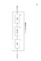
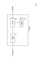
- the blow molding defect detection device 1 of this embodiment includes a recording unit 11, a signal processing unit 12, and a determination unit 13.
- the recording unit 11 records a sound (blown sound) generated by blowing compressed air into the parison using an acoustic microphone installed near the mold (S11).
- the recording unit 11 can be realized by equipment capable of recording a frequency band of 0 Hz to 40 kHz or higher.
- the signal processing unit 12 performs a process of emphasizing the change in the sound derived from the hole made in the parison with respect to the recorded blown sound signal. Specifically, the signal processing unit 12 weights the cepstrum coefficient of the blown sound signal using a preset window function, and outputs a processed signal obtained by converting the weighted cepstrum coefficient into the frequency domain (S12). ).
- the determination unit 13 determines the presence or absence of a hole in the processed signal emphasized in step S12 based on a certain standard. At this time, it is also possible to extract the acoustic feature amount from the sound that has undergone the normal manufacturing process in advance by machine learning or the like, and use this feature amount as a judgment criterion. In this embodiment, the determination unit 13 determines that the parison has a hole when the energy sum of frequencies higher than the preset boundary frequency of the processed signal exceeds a predetermined threshold value (S13). ..
- ⁇ Recording unit 11 (S11)>
- the recording unit 11 (microphone) is installed in the vicinity of the mold that sandwiches the molten parison. At this time, in order to record the sound (blown sound) generated by the compressed air being blown into the parison as well as possible in S / N, the distance between the mold and the recording unit 11 (microphone) is set as close as possible. .. Recording of the blowing sound starts at the same time as the compressed air is blown into the parison, and continues until the blowing of the compressed air is completed (Fig. 1).
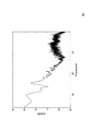
- FIG. 4 shows the frequency spectrum when no holes are formed during product manufacturing.
- FIG. 5 shows a frequency spectrum when a hole is formed during product manufacturing.
- the horizontal axis is a logarithmic display.
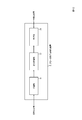
- the signal processing unit 12 includes a first FFT unit 121, a logarithmic power spectrum transform unit 122, an inverse FFT unit 123, a window function weighting unit 124, and a second FFT unit 125.
- the input blow-in sound signal (input signal) is a digital signal such as PCM, and the entire recorded blow-in sound data or only a certain time zone is extracted.
- the signal processing unit 12 calculates the cepstrum coefficient from the signal (input signal) of the blowing sound. At this time, a generally widely known method can be used for the calculation of cepstrum (Reference Non-Patent Document 1: Sadaoki Furui, “Digital Speech Processing", Tokai University Press, 2003, pp.44-47. ).
- the first FFT unit 121 performs FFT (Fast Fourier Transform) on the blown sound signal (input signal) and converts the blown sound signal into a frequency spectrum (S121).
- the logarithmic power spectrum conversion unit 122 converts the signal of the blowing sound converted into the frequency spectrum into the power spectrum of the logarithmic scale (S122).
- the inverse FFT unit 123 calculates the cepstrum coefficient by inverse FFT the signal of the blowing sound converted into the power spectrum of the logarithmic scale (S123).
- the window function weighting unit 124 calculates a coefficient obtained by weighting the calculated cepstrum coefficient using a preset window function (lifter) (S124).
- This window function removes the envelope of the spectrum and sets the fine structure to a coordinated value so that the peak of the spectrum can be obtained.
- the second FFT unit 125 outputs a signal (processed signal) converted into the frequency domain again by FFTing the weighted cepstrum coefficient (S125).
- S125 weighted cepstrum coefficient
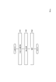
- the determination unit 13 includes an energy sum calculation unit 131, a comparison determination unit 132, and a threshold storage unit 13A.
- the determination unit 13 determines the presence or absence of a hole based on the processed signal calculated in step S12. Specifically, as shown in FIG. 11, the energy sum calculation unit 131 calculates the energy sum of a frequency band (shaded band of FIGS. 8 and 9) higher than the preset boundary frequency of the processed signal. Calculate (S131).
- the comparison determination unit 132 determines that the parison has a hole when the sum of energies is equal to or greater than a predetermined threshold value (S132). It is assumed that the threshold value to be compared with the energy sum is stored in the threshold value storage unit 13A in advance. For example, in the comparison determination unit 132, when the energy sum of the shaded portion in FIG. 8 is less than the threshold value and the energy sum of the shaded portion in FIG. 9 is equal to or more than the threshold value, the blow molded article corresponding to FIG. 8 has no hole. It is determined that the blow molded article corresponding to FIG. 9 has a hole.
- the blow molding defect detection device 2 of this embodiment includes a recording unit 11, a signal processing unit 22, and a determination unit 23.
- the recording unit 11 records the blowing sound (S11, the same as in the first embodiment).
- the signal processing unit 22 extracts the envelope shape of the frequency spectrum.
- the spectrum envelope can be obtained by the moving average method of averaging a plurality of adjacent frequency bins of the frequency spectrum expressed as a digital signal.
- a means using the cepstrum coefficient can be taken.
- the signal processing unit 22 weights the cepstrum coefficient of the blown sound signal using a preset window function, and outputs a processed signal obtained by converting the weighted cepstrum coefficient into the frequency domain (S22). ).
- the difference from the first embodiment is the window function.
- the lifting window function a window function in which the outline (envelope) of the spectrum is emphasized is used.
- the determination unit 23 is adjacent to an approximate straight line that approximates the waveform of the processed signal in a frequency band in which the power increase / decrease is small as compared with other frequency bands, and a frequency band in which the power increase / decrease is small, and the power is reduced.
- the crossing frequency which is the frequency at which the approximate straight lines that approximate the waveforms in the existing frequency domain intersect, is equal to or less than a predetermined threshold value, it is determined that the parison has a hole (S23).
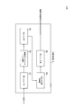
- the signal processing unit 22 includes a first FFT unit 121, a logarithmic power spectrum transform unit 122, an inverse FFT unit 123, a window function weighting unit 224, and a second FFT unit 125, and includes window function weighting.
- the configuration other than the part 224 is the same as that of the first embodiment.
- the window function weighting unit 224 uses a preset window function (lifter, but a window function in which the outline (encapsulation) of the spectrum is emphasized) for the cepstrum coefficient calculated in step S123. The weighted coefficient is calculated (S224).
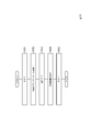
- the determination unit 23 includes a band division unit 231, a comparison determination unit 232, and a threshold storage unit 23A.
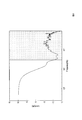
- the band dividing unit 231 has the highest power in the extremely low frequency region close to the DC component of the processed signal in step S22, the power decreases sharply from there, and the power increases again.
- the power is adjacent to the frequency band (band A), the frequency band (band B) where the power increase / decrease is small compared to other bands, and the frequency band where the power increase / decrease is small, although there is a slight increase / decrease in power.
- the frequency domain (band C) in which is decreasing is divided into three major bands, an approximate straight line that approximates the waveforms of band B and band C is calculated, and the intersection frequency, which is the frequency at which the two approximate straight lines intersect, is calculated.
- the approximate straight line of the band C can be obtained by a method of obtaining a regression line by the least squares method or the like for the level of each frequency bin of the band C.
- the comparison determination unit 232 determines that the parison has a hole when the intersection frequency is equal to or less than a predetermined threshold value (S232). It is assumed that the threshold value to be compared with the cross frequency is stored in the threshold value storage unit 23A in advance.
- FIG. 19 shows the results of determining the presence or absence of holes by the blow molding defect detection method of this embodiment from some sample data.
- the threshold was set to 7.8 kHz.
- blow molding defect detection method of Example 1 it is also possible to combine the blow molding defect detection method of Example 1 and the blow molding defect detection method of Example 2.
- the presence or absence of a hole is determined based on the and or or condition of the determination result of Example 1 and the determination result of Example 2.
- the device of the present invention is, for example, as a single hardware entity, an input unit to which a keyboard or the like can be connected, an output unit to which a liquid crystal display or the like can be connected, and a communication device (for example, a communication cable) capable of communicating outside the hardware entity.
- Communication unit to which can be connected CPU (Central Processing Unit, cache memory, registers, etc.), RAM and ROM which are memories, external storage device which is a hard disk, and input units, output units, and communication units of these.
- CPU, RAM, ROM has a connecting bus so that data can be exchanged between external storage devices.
- a device (drive) or the like capable of reading and writing a recording medium such as a CD-ROM may be provided in the hardware entity.
- a physical entity equipped with such hardware resources includes a general-purpose computer and the like.
- the external storage device of the hardware entity stores the program required to realize the above-mentioned functions and the data required for processing this program (not limited to the external storage device, for example, reading a program). It may be stored in a ROM, which is a dedicated storage device). Further, the data obtained by the processing of these programs is appropriately stored in a RAM, an external storage device, or the like.
- each program stored in the external storage device (or ROM, etc.) and the data necessary for processing each program are read into the memory as needed, and are appropriately interpreted, executed, and processed by the CPU. ..
- the CPU realizes a predetermined function (each configuration requirement represented by the above, ... Department, ... means, etc.).
- the present invention is not limited to the above-described embodiment, and can be appropriately modified without departing from the spirit of the present invention. Further, the processes described in the above-described embodiment are not only executed in chronological order according to the order described, but may also be executed in parallel or individually depending on the processing capacity of the device that executes the processes or if necessary. ..
- the processing function in the hardware entity (device of the present invention) described in the above embodiment is realized by a computer
- the processing content of the function that the hardware entity should have is described by a program.
- the processing function in the above hardware entity is realized on the computer.
- the various processes described above can be performed by causing the recording unit 10020 of the computer shown in FIG. 20 to read a program for executing each step of the above method and operating the control unit 10010, the input unit 10030, the output unit 10040, and the like. ..
- the program that describes this processing content can be recorded on a computer-readable recording medium.
- the computer-readable recording medium may be, for example, a magnetic recording device, an optical disk, a photomagnetic recording medium, a semiconductor memory, or the like.
- a hard disk device, a flexible disk, a magnetic tape, or the like as a magnetic recording device is used as an optical disk
- a DVD (Digital Versatile Disc), a DVD-RAM (Random Access Memory), or a CD-ROM (Compact Disc Read Only) is used as an optical disk.
- Memory CD-R (Recordable) / RW (ReWritable), etc.
- MO Magnetto-Optical disc
- magneto-optical recording media EEPROM (Electrically Erasable and Programmable-Read Only Memory), etc. as semiconductor memory Can be used.
- the distribution of this program is carried out, for example, by selling, transferring, renting, etc., a portable recording medium such as a DVD or CD-ROM on which the program is recorded. Further, the program may be stored in the storage device of the server computer, and the program may be distributed by transferring the program from the server computer to another computer via a network.
- a computer that executes such a program first stores, for example, a program recorded on a portable recording medium or a program transferred from a server computer in its own storage device. Then, when the process is executed, the computer reads the program stored in its own recording medium and executes the process according to the read program. Further, as another execution form of this program, a computer may read the program directly from a portable recording medium and execute processing according to the program, and further, the program is transferred from the server computer to this computer. Each time, the processing according to the received program may be executed sequentially. In addition, the above processing is executed by a so-called ASP (Application Service Provider) type service that realizes the processing function only by the execution instruction and result acquisition without transferring the program from the server computer to this computer. May be.
- the program in this embodiment includes information to be used for processing by a computer and equivalent to the program (data that is not a direct command to the computer but has a property of defining the processing of the computer, etc.).
- the hardware entity is configured by executing a predetermined program on the computer, but at least a part of these processing contents may be realized in terms of hardware.
Landscapes
- Physics & Mathematics (AREA)
- General Physics & Mathematics (AREA)
- Blow-Moulding Or Thermoforming Of Plastics Or The Like (AREA)
Abstract
ブロー成形による中空製品の成形時に発生する微小な穴あきを検知することができるブロー成形不良検知装置を提供する。圧縮エアーがパリソンに吹き込まれることにより発生する吹き込み音を収録する収録部と、吹き込み音の信号のケプストラム係数に予め設定した窓関数を用いて重み付けし、重みづけされたケプストラム係数を周波数領域に変換した処理済み信号を出力する信号処理部と、処理済み信号の予め設定された境界周波数より高い周波数のエネルギー和が所定の閾値以上となった場合に、パリソンに穴が空いていると判定する判定部を含む。
Description
本発明は、ブロー成形物の成形不良(穴あき)を検知するブロー成形不良検知装置、ブロー成形不良検知方法、プログラムに関する。
プラスチック製品の加工整形方法のひとつとして、熱により柔らかくした樹脂(熱可塑性樹脂)をパイプ状に押し出し(パリソン)、樹脂が柔らかい状態でパリソン内に圧縮エアーを吹き込み、樹脂を金型に押し当て冷却・固化させ成形するブロー成形がある(図1)。これは、ペットボトルやポリタンクなど、中空の製品を作るのに用いられる。
この手法でペットボトルなどを整形した場合、なんらかの理由で成形後の製品に微小な穴があくことがある。この穴が開いた製品を市場に出してしまうと、流通過程で内容物が漏れるおそれがあるほか、顧客がペットボトルの内容物を利用する際に、不都合が生じることが想定され、出荷前に穴の存在を検出する必要がある。
現在でも、圧縮エアーの気圧の変化を手掛かりにして穴の発生を検知する方法(特許文献1)や、成形後の製品に対して画像検知技術を利用して穴の存在を検出する方法(特許文献2)などの対策が取られている。
例えば、圧縮エアーの気圧変化を手掛かりにする方法(特許文献1)では、穴の直径が数mm以下の極小さい穴では気圧の変化が極わずかであり、穴の発生の検知が困難である。一方画像を用いた方法(特許文献2)においても、成形物である製品のデザインなどの凹凸の影に隠れた穴の存在が検知できない場合がある。
そこで本発明では、ブロー成形による中空製品の成形時に発生する微小な穴あきを検知することができるブロー成形不良検知装置を提供することを目的とする。
本発明のブロー成形不良検知装置は、収録部と、信号処理部と、判定部を含む。
収録部は、圧縮エアーがパリソンに吹き込まれることにより発生する吹き込み音を収録する。信号処理部は、吹き込み音の信号のケプストラム係数に予め設定した窓関数を用いて重み付けし、重みづけされたケプストラム係数を周波数領域に変換した処理済み信号を出力する。判定部は、処理済み信号の予め設定された境界周波数より高い周波数のエネルギー和が所定の閾値以上となった場合に、パリソンに穴が空いていると判定する。
本発明のブロー成形不良検知装置によれば、ブロー成形による中空製品の成形時に発生する微小な穴あきを検知することができる。
以下、本発明の実施の形態について、詳細に説明する。なお、同じ機能を有する構成部には同じ番号を付し、重複説明を省略する。
以下、図2を参照して、実施例1のブロー成形不良検知装置1の構成を説明する。同図に示すように、本実施例のブロー成形不良検知装置1は、収録部11と、信号処理部12と、判定部13を含む。
図3に示すように、収録部11は、金型の近傍に設置した音響マイクを用いて、圧縮エアーがパリソンに吹き込まれることにより発生する音(吹き込み音)を収録する(S11)。収録部11は、0Hz~40kHz以上の周波数帯域が収録できる機材により実現できる。
信号処理部12は、収録された吹き込み音の信号に対して、パリソンに空いた穴に由来する音の変化を強調する処理を施す。具体的には、信号処理部12は、吹き込み音の信号のケプストラム係数に予め設定した窓関数を用いて重み付けし、重みづけされたケプストラム係数を周波数領域に変換した処理済み信号を出力する(S12)。
判定部13は、ステップS12で強調処理された処理済み信号に対し、一定の基準に基づいて穴の有無を判別する。この際、あらかじめ正常な製造過程を経た音から機械学習などによりその音響特徴量を抽出し、この特徴量を判断基準として用いることもできる。本実施例では、判定部13は、処理済み信号の予め設定された境界周波数より高い周波数のエネルギー和が所定の閾値以上となった場合に、パリソンに穴が空いていると判定する(S13)。
各構成要件の詳細な動作を下記に述べる。
<収録部11(S11)>
収録部11(マイク)は、溶融状態のパリソンを挟み込む金型の近傍に設置される。この際、圧縮エアーがパリソンに吹き込まれることにより発生する音(吹き込み音)を、出来る限りS/N良く収録するために、金型と収録部11(マイク)の距離は最大限近づけて設置する。吹き込み音の収録は、パリソンへの圧縮エアーの吹き込みと同時に開始し、圧縮エアーの吹き込みが終了するまで継続させる(図1)。
収録部11(マイク)は、溶融状態のパリソンを挟み込む金型の近傍に設置される。この際、圧縮エアーがパリソンに吹き込まれることにより発生する音(吹き込み音)を、出来る限りS/N良く収録するために、金型と収録部11(マイク)の距離は最大限近づけて設置する。吹き込み音の収録は、パリソンへの圧縮エアーの吹き込みと同時に開始し、圧縮エアーの吹き込みが終了するまで継続させる(図1)。
図4に製品製造時に穴が空かなかった場合の周波数スペクトルを示す。図5に製品製造時に穴が空いた場合の周波数スペクトルを示す。なお、各図の周波数スペクトルは、横軸を対数表示としている。
図4、図5を比べると、概ね2000Hz以上の周波数スペクトルの特徴の違いを評価することで、穴の有無の判別の可能性が伺える。ただし、この周波数スペクトルのままでは、特徴の違いを定量的に評価することが困難である。
<信号処理部12(S12)>
そこで、ステップS12で穴の有無による周波数スペクトルの特徴の違いを明確にする処理を施す。図6に示すように、信号処理部12は、第1FFT部121と、対数パワースペクトル変換部122と、逆FFT部123と、窓関数重み付け部124と、第2FFT部125を含む。
そこで、ステップS12で穴の有無による周波数スペクトルの特徴の違いを明確にする処理を施す。図6に示すように、信号処理部12は、第1FFT部121と、対数パワースペクトル変換部122と、逆FFT部123と、窓関数重み付け部124と、第2FFT部125を含む。
入力される吹き込み音の信号(入力信号)は、PCMなどのディジタル信号であり、収録された吹き込み音のデータ全体、もしくは一定の時間帯のみが抽出されたものである。信号処理部12は、この吹き込み音の信号(入力信号)からケプストラム係数を算出する。この際、ケプストラムの計算は、一般に広く知られている方法を用いることができる(参考非特許文献1:古井貞熙、「ディジタル音声処理」、東海大学出版会、2003年、pp.44-47)。
すなわち、図7に示すように、第1FFT部121は、吹き込み音の信号(入力信号)をFFT(高速フーリエ変換)して、吹き込み音の信号を周波数スペクトルに変換する(S121)。対数パワースペクトル変換部122は、周波数スペクトルに変換された吹き込み音の信号を、対数尺度のパワースペクトルに変換する(S122)。逆FFT部123は、対数尺度のパワースペクトルに変換された吹き込み音の信号を、逆FFTしてケプストラム係数を算出する(S123)。窓関数重み付け部124は、算出されたケプストラム係数に、あらかじめ設定した窓関数(リフター)を用いて重みづけをした係数を算出する(S124)。この窓関数は、スペクトルのピークが取得できるよう、スペクトルの包絡を取り除き、微細構造が協調される値に設定する。最後に、第2FFT部125は、重みづけされたケプストラム係数をFFTすることで再度周波数領域に変換した信号(処理済み信号)を出力する(S125)。図4、図5に示した周波数スペクトルの例をこの方法で処理した結果を、それぞれ図8、図9に示す。
<判定部13>
図10に示すように、判定部13は、エネルギー和計算部131と、比較判定部132と、閾値記憶部13Aを含む。
図10に示すように、判定部13は、エネルギー和計算部131と、比較判定部132と、閾値記憶部13Aを含む。
判定部13は、ステップS12で算出された処理済み信号を基に、穴の有無の判定を行う。具体的には、図11に示すように、エネルギー和計算部131は、処理済み信号の予め設定された境界周波数より高い周波数の帯域(図8、図9の網掛けした帯域)のエネルギー和を計算する(S131)。比較判定部132は、エネルギー和が所定の閾値以上となった場合に、パリソンに穴が空いていると判定する(S132)。エネルギー和と比較される閾値は予め閾値記憶部13Aに記憶済みであるものとする。例えば比較判定部132は、図8の網掛け部分のエネルギー和が閾値未満となり、図9の網掛け部分のエネルギー和が閾値以上となる場合に、図8に対応するブロー成形物は穴が無いと判定し、図9に対応するブロー成形物は穴が空いていると判定する。
以下、図12を参照して実施例2のブロー成形不良検知装置2の構成を説明する。同図に示すように、本実施例のブロー成形不良検知装置2は、収録部11と、信号処理部22と、判定部23を含む。
図13に示すように、収録部11は吹き込み音を収録する(S11、実施例1と同様)。
信号処理部22は、周波数スペクトルの包絡形状を抽出する。このひとつの手段として、ディジタル信号として表現されている周波数スペクトルの隣接した複数の周波数binの平均をとる移動平均法でスペクトル包絡を求めることができる。あるいは、実施例1と同様に、ケプストラム係数を用いる手段も取りえる。具体的には、信号処理部22は、吹き込み音の信号のケプストラム係数に予め設定した窓関数を用いて重み付けし、重みづけされたケプストラム係数を周波数領域に変換した処理済み信号を出力する(S22)。実施例1との違いは、窓関数である。本実施例では、リフタリングの窓関数として、スペクトルの概形(包絡)が強調される窓関数を用いる。
判定部23は、処理済み信号の、他の周波数帯域と比較してパワーの増減が少ない周波数帯域の波形を近似した近似直線と、パワーの増減が少ない周波数帯域に隣接し、パワーが減少している周波数領域の波形を近似した近似直線が交差する周波数である交差周波数が所定の閾値以下となった場合に、パリソンに穴が空いていると判定する(S23)。
信号処理部22、判定部23の詳細な動作を下記に述べる。
<信号処理部22(S22)>
図14に示すように、信号処理部22は、第1FFT部121と、対数パワースペクトル変換部122と、逆FFT部123と、窓関数重み付け部224と、第2FFT部125を含み、窓関数重み付け部224以外の構成については実施例1と同じである。図15に示すように、窓関数重み付け部224は、ステップS123で算出されたケプストラム係数に、あらかじめ設定した窓関数(リフター、ただしスペクトルの概形(包絡)が強調される窓関数)を用いて重みづけをした係数を算出する(S224)。
図14に示すように、信号処理部22は、第1FFT部121と、対数パワースペクトル変換部122と、逆FFT部123と、窓関数重み付け部224と、第2FFT部125を含み、窓関数重み付け部224以外の構成については実施例1と同じである。図15に示すように、窓関数重み付け部224は、ステップS123で算出されたケプストラム係数に、あらかじめ設定した窓関数(リフター、ただしスペクトルの概形(包絡)が強調される窓関数)を用いて重みづけをした係数を算出する(S224)。
<判定部23>
図16に示すように、判定部23は、帯域分割部231と、比較判定部232と、閾値記憶部23Aを含む。
図16に示すように、判定部23は、帯域分割部231と、比較判定部232と、閾値記憶部23Aを含む。
帯域分割部231は、図18に例示するように、ステップS22の処理済み信号を、直流成分に近い極低周波数領域のパワーが一番大きく、そこから急激にパワーが減少し、再びパワーが上昇している周波数帯域(帯域A)、パワーの多少の増減はあるものの、他の帯域に比べてパワーの増減が少ない周波数帯域(帯域B)、およびパワーの増減が少ない周波数帯域に隣接し、パワーが減少している周波数領域(帯域C)の大きく3つの帯域に分割して、帯域B、帯域Cの波形を近似した近似直線を算出し、2つの近似直線が交差する周波数である交差周波数を取得する(S231)。帯域Cの近似直線は、帯域Cの各周波数binのレベルを最小二乗法などにより回帰直線を得る方法などで取得できる。
比較判定部232は、交差周波数が所定の閾値以下となった場合に、パリソンに穴が空いていると判定する(S232)。交差周波数と比較される閾値は予め閾値記憶部23Aに記憶済みであるものとする。
図19に、いくつかのサンプルデータから本実施例のブロー成形不良検知方法により穴の有無を判別した結果を示す。この例では、閾値を7.8kHzと設定した。
実施例1のブロー成形不良検知方法と実施例2のブロー成形不良検知方法を組み合わせることも可能である。この場合、実施例1の判定結果と実施例2の判定結果のandもしくはor条件で穴の有無の判別を行う。
<補記>
本発明の装置は、例えば単一のハードウェアエンティティとして、キーボードなどが接続可能な入力部、液晶ディスプレイなどが接続可能な出力部、ハードウェアエンティティの外部に通信可能な通信装置(例えば通信ケーブル)が接続可能な通信部、CPU(Central Processing Unit、キャッシュメモリやレジスタなどを備えていてもよい)、メモリであるRAMやROM、ハードディスクである外部記憶装置並びにこれらの入力部、出力部、通信部、CPU、RAM、ROM、外部記憶装置の間のデータのやり取りが可能なように接続するバスを有している。また必要に応じて、ハードウェアエンティティに、CD-ROMなどの記録媒体を読み書きできる装置(ドライブ)などを設けることとしてもよい。このようなハードウェア資源を備えた物理的実体としては、汎用コンピュータなどがある。
本発明の装置は、例えば単一のハードウェアエンティティとして、キーボードなどが接続可能な入力部、液晶ディスプレイなどが接続可能な出力部、ハードウェアエンティティの外部に通信可能な通信装置(例えば通信ケーブル)が接続可能な通信部、CPU(Central Processing Unit、キャッシュメモリやレジスタなどを備えていてもよい)、メモリであるRAMやROM、ハードディスクである外部記憶装置並びにこれらの入力部、出力部、通信部、CPU、RAM、ROM、外部記憶装置の間のデータのやり取りが可能なように接続するバスを有している。また必要に応じて、ハードウェアエンティティに、CD-ROMなどの記録媒体を読み書きできる装置(ドライブ)などを設けることとしてもよい。このようなハードウェア資源を備えた物理的実体としては、汎用コンピュータなどがある。
ハードウェアエンティティの外部記憶装置には、上述の機能を実現するために必要となるプログラムおよびこのプログラムの処理において必要となるデータなどが記憶されている(外部記憶装置に限らず、例えばプログラムを読み出し専用記憶装置であるROMに記憶させておくこととしてもよい)。また、これらのプログラムの処理によって得られるデータなどは、RAMや外部記憶装置などに適宜に記憶される。
ハードウェアエンティティでは、外部記憶装置(あるいはROMなど)に記憶された各プログラムとこの各プログラムの処理に必要なデータが必要に応じてメモリに読み込まれて、適宜にCPUで解釈実行・処理される。その結果、CPUが所定の機能(上記、…部、…手段などと表した各構成要件)を実現する。
本発明は上述の実施形態に限定されるものではなく、本発明の趣旨を逸脱しない範囲で適宜変更が可能である。また、上記実施形態において説明した処理は、記載の順に従って時系列に実行されるのみならず、処理を実行する装置の処理能力あるいは必要に応じて並列的にあるいは個別に実行されるとしてもよい。
既述のように、上記実施形態において説明したハードウェアエンティティ(本発明の装置)における処理機能をコンピュータによって実現する場合、ハードウェアエンティティが有すべき機能の処理内容はプログラムによって記述される。そして、このプログラムをコンピュータで実行することにより、上記ハードウェアエンティティにおける処理機能がコンピュータ上で実現される。
上述の各種の処理は、図20に示すコンピュータの記録部10020に、上記方法の各ステップを実行させるプログラムを読み込ませ、制御部10010、入力部10030、出力部10040などに動作させることで実施できる。
この処理内容を記述したプログラムは、コンピュータで読み取り可能な記録媒体に記録しておくことができる。コンピュータで読み取り可能な記録媒体としては、例えば、磁気記録装置、光ディスク、光磁気記録媒体、半導体メモリ等どのようなものでもよい。具体的には、例えば、磁気記録装置として、ハードディスク装置、フレキシブルディスク、磁気テープ等を、光ディスクとして、DVD(Digital Versatile Disc)、DVD-RAM(Random Access Memory)、CD-ROM(Compact Disc Read Only Memory)、CD-R(Recordable)/RW(ReWritable)等を、光磁気記録媒体として、MO(Magneto-Optical disc)等を、半導体メモリとしてEEP-ROM(Electrically Erasable and Programmable-Read Only Memory)等を用いることができる。
また、このプログラムの流通は、例えば、そのプログラムを記録したDVD、CD-ROM等の可搬型記録媒体を販売、譲渡、貸与等することによって行う。さらに、このプログラムをサーバコンピュータの記憶装置に格納しておき、ネットワークを介して、サーバコンピュータから他のコンピュータにそのプログラムを転送することにより、このプログラムを流通させる構成としてもよい。
このようなプログラムを実行するコンピュータは、例えば、まず、可搬型記録媒体に記録されたプログラムもしくはサーバコンピュータから転送されたプログラムを、一旦、自己の記憶装置に格納する。そして、処理の実行時、このコンピュータは、自己の記録媒体に格納されたプログラムを読み取り、読み取ったプログラムに従った処理を実行する。また、このプログラムの別の実行形態として、コンピュータが可搬型記録媒体から直接プログラムを読み取り、そのプログラムに従った処理を実行することとしてもよく、さらに、このコンピュータにサーバコンピュータからプログラムが転送されるたびに、逐次、受け取ったプログラムに従った処理を実行することとしてもよい。また、サーバコンピュータから、このコンピュータへのプログラムの転送は行わず、その実行指示と結果取得のみによって処理機能を実現する、いわゆるASP(Application Service Provider)型のサービスによって、上述の処理を実行する構成としてもよい。なお、本形態におけるプログラムには、電子計算機による処理の用に供する情報であってプログラムに準ずるもの(コンピュータに対する直接の指令ではないがコンピュータの処理を規定する性質を有するデータ等)を含むものとする。
また、この形態では、コンピュータ上で所定のプログラムを実行させることにより、ハードウェアエンティティを構成することとしたが、これらの処理内容の少なくとも一部をハードウェア的に実現することとしてもよい。
Claims (5)
- 圧縮エアーがパリソンに吹き込まれることにより発生する吹き込み音を収録する収録部と、
前記吹き込み音の信号のケプストラム係数に予め設定した窓関数を用いて重み付けし、重みづけされたケプストラム係数を周波数領域に変換した処理済み信号を出力する信号処理部と、
前記処理済み信号の予め設定された境界周波数より高い周波数のエネルギー和が所定の閾値以上となった場合に、前記パリソンに穴が空いていると判定する判定部を含む
ブロー成形不良検知装置。 - 圧縮エアーがパリソンに吹き込まれることにより発生する吹き込み音を収録する収録部と、
前記吹き込み音の信号のケプストラム係数に予め設定した窓関数を用いて重み付けし、重みづけされたケプストラム係数を周波数領域に変換した処理済み信号を出力する信号処理部と、
前記処理済み信号の、他の周波数帯域と比較してパワーの増減が少ない周波数帯域の波形を近似した近似直線と、パワーの増減が少ない周波数帯域に隣接し、パワーが減少している周波数領域の波形を近似した近似直線が交差する周波数である交差周波数が所定の閾値以下となった場合に、前記パリソンに穴が空いていると判定する判定部を含む
ブロー成形不良検知装置。 - 圧縮エアーがパリソンに吹き込まれることにより発生する吹き込み音を収録するステップと、
前記吹き込み音の信号のケプストラム係数に予め設定した窓関数を用いて重み付けし、重みづけされたケプストラム係数を周波数領域に変換した処理済み信号を出力するステップと、
前記処理済み信号の予め設定された境界周波数より高い周波数のエネルギー和が所定の閾値以上となった場合に、前記パリソンに穴が空いていると判定するステップを含む
ブロー成形不良検知方法。 - 圧縮エアーがパリソンに吹き込まれることにより発生する吹き込み音を収録するステップと、
前記吹き込み音の信号のケプストラム係数に予め設定した窓関数を用いて重み付けし、重みづけされたケプストラム係数を周波数領域に変換した処理済み信号を出力するステップと、
前記処理済み信号の、他の周波数帯域と比較してパワーの増減が少ない周波数帯域の波形を近似した近似直線と、パワーの増減が少ない周波数帯域に隣接し、パワーが減少している周波数領域の波形を近似した近似直線が交差する周波数である交差周波数が所定の閾値以下となった場合に、前記パリソンに穴が空いていると判定するステップを含む
ブロー成形不良検知方法。 - コンピュータを請求項1または2に記載のブロー成形不良検知装置として機能させるプログラム。
Priority Applications (1)
| Application Number | Priority Date | Filing Date | Title |
|---|---|---|---|
| PCT/JP2019/047681 WO2021111602A1 (ja) | 2019-12-05 | 2019-12-05 | ブロー成形不良検知装置、ブロー成形不良検知方法、プログラム |
Applications Claiming Priority (1)
| Application Number | Priority Date | Filing Date | Title |
|---|---|---|---|
| PCT/JP2019/047681 WO2021111602A1 (ja) | 2019-12-05 | 2019-12-05 | ブロー成形不良検知装置、ブロー成形不良検知方法、プログラム |
Publications (1)
| Publication Number | Publication Date |
|---|---|
| WO2021111602A1 true WO2021111602A1 (ja) | 2021-06-10 |
Family
ID=76221710
Family Applications (1)
| Application Number | Title | Priority Date | Filing Date |
|---|---|---|---|
| PCT/JP2019/047681 Ceased WO2021111602A1 (ja) | 2019-12-05 | 2019-12-05 | ブロー成形不良検知装置、ブロー成形不良検知方法、プログラム |
Country Status (1)
| Country | Link |
|---|---|
| WO (1) | WO2021111602A1 (ja) |
Citations (4)
| Publication number | Priority date | Publication date | Assignee | Title |
|---|---|---|---|---|
| JPS58184542A (ja) * | 1982-04-22 | 1983-10-28 | Toshiba Corp | 音響異常検出方式 |
| JPH04298322A (ja) * | 1991-03-27 | 1992-10-22 | Ube Ind Ltd | ブロー成形機の不良判別装置 |
| JP2003525147A (ja) * | 2000-03-01 | 2003-08-26 | シパ ソシエタ ペル アチオニ | 吹込成形された容器の破裂を自動検出するための装置を備えた吹込成形プラント |
| CN109668058A (zh) * | 2018-12-24 | 2019-04-23 | 哈尔滨工业大学 | 基于线性预测倒谱系数和lyapunov指数的供水管道漏损辨识方法 |
-
2019
- 2019-12-05 WO PCT/JP2019/047681 patent/WO2021111602A1/ja not_active Ceased
Patent Citations (4)
| Publication number | Priority date | Publication date | Assignee | Title |
|---|---|---|---|---|
| JPS58184542A (ja) * | 1982-04-22 | 1983-10-28 | Toshiba Corp | 音響異常検出方式 |
| JPH04298322A (ja) * | 1991-03-27 | 1992-10-22 | Ube Ind Ltd | ブロー成形機の不良判別装置 |
| JP2003525147A (ja) * | 2000-03-01 | 2003-08-26 | シパ ソシエタ ペル アチオニ | 吹込成形された容器の破裂を自動検出するための装置を備えた吹込成形プラント |
| CN109668058A (zh) * | 2018-12-24 | 2019-04-23 | 哈尔滨工业大学 | 基于线性预测倒谱系数和lyapunov指数的供水管道漏损辨识方法 |
Similar Documents
| Publication | Publication Date | Title |
|---|---|---|
| US8036884B2 (en) | Identification of the presence of speech in digital audio data | |
| US20120143363A1 (en) | Audio event detection method and apparatus | |
| US9451304B2 (en) | Sound feature priority alignment | |
| JP4572218B2 (ja) | 音楽区間検出方法、音楽区間検出装置、音楽区間検出プログラム及び記録媒体 | |
| CN105261357A (zh) | 基于统计模型的语音端点检测方法及装置 | |
| JP6676009B2 (ja) | 話者判定装置、話者判定情報生成方法、プログラム | |
| CN101714380A (zh) | 音频播放器支持的音频文件格式的测试设备及方法 | |
| Ellis et al. | Classifying soundtracks with audio texture features | |
| JP2017058507A (ja) | 音声認識装置、音声認識方法、プログラム | |
| JPWO2019107170A1 (ja) | 緊急度推定装置、緊急度推定方法、プログラム | |
| JP6452591B2 (ja) | 合成音声品質評価装置、合成音声品質評価方法、プログラム | |
| WO2021111602A1 (ja) | ブロー成形不良検知装置、ブロー成形不良検知方法、プログラム | |
| CN104217731A (zh) | 一种快速识别独奏乐曲乐谱的方法 | |
| CN105810222A (zh) | 一种音频设备的缺陷检测方法、装置及系统 | |
| Yarra et al. | A mode-shape classification technique for robust speech rate estimation and syllable nuclei detection | |
| WO2020209337A1 (ja) | 識別装置、識別方法、識別処理プログラム、生成装置、生成方法、および生成処理プログラム | |
| US11756554B2 (en) | Attribute identification method, and program | |
| JP5538350B2 (ja) | 音声認識方法とその装置とプログラム | |
| JP2018132678A (ja) | ターンテイキングタイミング識別装置、ターンテイキングタイミング識別方法、プログラム、記録媒体 | |
| JP5046000B2 (ja) | 検出装置、方法、及びプログラム | |
| JP2011085824A (ja) | 音響識別装置、その処理方法およびプログラム | |
| US20220036238A1 (en) | Mono channel burst classification using machine learning | |
| JP7176629B2 (ja) | 識別モデル学習装置、識別装置、識別モデル学習方法、識別方法、プログラム | |
| JP5496945B2 (ja) | 話者分類装置、話者分類方法、プログラム | |
| JP2022027736A (ja) | 分類システムとデータ・バーストの分類方法 |
Legal Events
| Date | Code | Title | Description |
|---|---|---|---|
| 121 | Ep: the epo has been informed by wipo that ep was designated in this application |
Ref document number: 19954792 Country of ref document: EP Kind code of ref document: A1 |
|
| NENP | Non-entry into the national phase |
Ref country code: DE |
|
| 122 | Ep: pct application non-entry in european phase |
Ref document number: 19954792 Country of ref document: EP Kind code of ref document: A1 |
|
| NENP | Non-entry into the national phase |
Ref country code: JP |