WO2021106086A1 - 鋼及び軸受 - Google Patents
鋼及び軸受 Download PDFInfo
- Publication number
- WO2021106086A1 WO2021106086A1 PCT/JP2019/046228 JP2019046228W WO2021106086A1 WO 2021106086 A1 WO2021106086 A1 WO 2021106086A1 JP 2019046228 W JP2019046228 W JP 2019046228W WO 2021106086 A1 WO2021106086 A1 WO 2021106086A1
- Authority
- WO
- WIPO (PCT)
- Prior art keywords
- less
- steel
- content
- bearing
- carburizing
- Prior art date
Links
Images


Classifications
-
- C—CHEMISTRY; METALLURGY
- C22—METALLURGY; FERROUS OR NON-FERROUS ALLOYS; TREATMENT OF ALLOYS OR NON-FERROUS METALS
- C22C—ALLOYS
- C22C38/00—Ferrous alloys, e.g. steel alloys
-
- C—CHEMISTRY; METALLURGY
- C22—METALLURGY; FERROUS OR NON-FERROUS ALLOYS; TREATMENT OF ALLOYS OR NON-FERROUS METALS
- C22C—ALLOYS
- C22C38/00—Ferrous alloys, e.g. steel alloys
- C22C38/12—Ferrous alloys, e.g. steel alloys containing tungsten, tantalum, molybdenum, vanadium, or niobium
-
- C—CHEMISTRY; METALLURGY
- C22—METALLURGY; FERROUS OR NON-FERROUS ALLOYS; TREATMENT OF ALLOYS OR NON-FERROUS METALS
- C22C—ALLOYS
- C22C38/00—Ferrous alloys, e.g. steel alloys
- C22C38/18—Ferrous alloys, e.g. steel alloys containing chromium
- C22C38/40—Ferrous alloys, e.g. steel alloys containing chromium with nickel
- C22C38/48—Ferrous alloys, e.g. steel alloys containing chromium with nickel with niobium or tantalum
-
- C—CHEMISTRY; METALLURGY
- C21—METALLURGY OF IRON
- C21D—MODIFYING THE PHYSICAL STRUCTURE OF FERROUS METALS; GENERAL DEVICES FOR HEAT TREATMENT OF FERROUS OR NON-FERROUS METALS OR ALLOYS; MAKING METAL MALLEABLE, e.g. BY DECARBURISATION OR TEMPERING
- C21D1/00—General methods or devices for heat treatment, e.g. annealing, hardening, quenching or tempering
- C21D1/06—Surface hardening
-
- C—CHEMISTRY; METALLURGY
- C21—METALLURGY OF IRON
- C21D—MODIFYING THE PHYSICAL STRUCTURE OF FERROUS METALS; GENERAL DEVICES FOR HEAT TREATMENT OF FERROUS OR NON-FERROUS METALS OR ALLOYS; MAKING METAL MALLEABLE, e.g. BY DECARBURISATION OR TEMPERING
- C21D9/00—Heat treatment, e.g. annealing, hardening, quenching or tempering, adapted for particular articles; Furnaces therefor
- C21D9/36—Heat treatment, e.g. annealing, hardening, quenching or tempering, adapted for particular articles; Furnaces therefor for balls; for rollers
Definitions
- the present invention relates to a steel that is subsequently carburized and hardened and tempered, and a bearing that is manufactured by carburizing and quenching using the steel.
- the above-mentioned predetermined steel material is subjected to hot working (for example, hot forging) and then cutting to obtain an intermediate product having a predetermined shape.
- the intermediate product is heat-treated to adjust the hardness and microstructure of the intermediate product to a predetermined state to obtain a desired mechanical part.
- the above heat treatment is quenching and tempering, whereas when skin-baked steel is used as the steel material, the above heat treatment is carburizing treatment (carburizing and tempering and tempering).
- Patent Document 1 Japanese Patent Application Laid-Open No. 8-49057
- Patent Document 2 Japanese Patent Application Laid-Open No. 2008-280583
- Patent Document 3 Japanese Patent Application Laid-Open No. 2008-25793
- Patent Document 1 discloses that a rolling bearing having excellent wear resistance can be obtained by subjecting a steel material containing a large amount of V to carburizing treatment or carburizing nitriding treatment and precipitating V carbide on the surface layer. Has been done.
- Patent Document 1 contains 0.50% or more of Cr, coarse carbides such as M 7 C 3 containing Cr as a main component may be produced at the time of carburizing depending on the amount of V and Mo added. It may be generated and the wear resistance of the bearing member may not be sufficiently obtained.
- Patent Document 2 focuses on the reduction of peeling life due to hydrogen embrittlement in bearings, finely disperses V-based carbides, and enhances the effect of hydrogen trap sites, whereby bearings with high surface fatigue strength can be obtained. Skin-baked steel is disclosed.
- a rolling bearing having improved wear resistance and peeling resistance can be obtained by dispersing fine carbides having a particle size of 10 ⁇ m or less at an area ratio of 7% or more and 15% or less.
- Bearing steel is disclosed.
- the bearing steel of Patent Document 3 not only contains 0.5% or more of expensive Ni, but also needs to be reheated and quenched after carburizing, which may increase the manufacturing cost.
- Patent Document 4 describes the amount of C and N on the surface portion as 0.05 ⁇ C ⁇ 1.0% and 0.8% by weight ratio with the object of improving fatigue strength, particularly rolling fatigue life.
- Patent Document 5 by limiting the quenching start temperature T A which is performed after the surface hardening treatment as described below, discloses that to obtain a high dimensional accuracy hardened mechanical parts.
- T 1 788-117 x [C] + 29 x [Si] -14 x [Mn]
- T 1 900-387 x [C] + 63 x [Si] -18 x [Mn]
- Patent Documents 4 and 5 suggests the necessity of securing the area ratio of carbides.
- the steel parts disclosed in Patent Document 4 and the skin-baking steel disclosed in Patent Document 5 have room for improvement in wear resistance.
- the present invention has been made in view of the above matters, and provides a steel suitable for obtaining a bearing having excellent wear resistance and surface origin peeling resistance, and a bearing using the steel.
- the purpose is.
- the present inventors have diligently studied to solve the above problems. As a result, in addition to adopting a predetermined chemical composition, the present inventors pay particular attention to the relationship between the Mo content and the V content, and the aspect ratio of the predetermined size is 2 only by carbide and quenching. It was found that it is possible to disperse carbides of .0 or less, and thus to provide a bearing having excellent wear resistance and surface origin peeling resistance.
- the present invention has been completed based on the above findings, and the gist thereof is as shown below.
- the chemical composition in the depth region of 1.50 mm or more from the surface is mass%.
- C 0.15 to 0.45%
- Si 0 to 3.00%
- Mn 0.20 to 1.50%
- Mo 0.70 to 3.00%
- V 0.40 to 1.00%
- Al 0.005 to 0.100%
- Is contained and the balance is Fe and impurities.
- P 0.015% or less
- S 0.005% or less
- N 0.0300% or less
- O 0.0015% or less, respectively.
- the chemical composition satisfies the formulas (1) and (2). 1.2 ⁇ Mo / V ⁇ 3.0 ...
- the C content is 0.70% to 1.50% by mass, and the content of components other than C is 1.5 mm or more from the surface.
- the area ratio of retained austenite is 15% or less,
- the area ratio of the precipitate having an aspect ratio of 2.0 or less and a circle equivalent diameter of 20 to 200 nm is 3.0% or more.
- the rest is tempered martensite tissue, The area ratio of the precipitate is 3.0% to 10.0%.
- a bearing characterized in that, in a surface layer having a depth region of 0 to 0.20 mm from the surface, the crystal grain size of the former austenite grain boundary is 10 or more in JIS grain size number, and the Vickers hardness is 700 HV or more.
- the composition of various elements and the relationship between the Mo content and the V content are particularly optimized.
- excellent performance can be realized in both wear resistance and surface origin peeling resistance.
- FIG. 1 is a side view and a cross-sectional view showing a partial cross section of an intermediate product (cylindrical test piece).
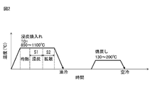
- FIG. 2 is a diagram showing a heat pattern of carburizing and quenching and tempering for an example of the present invention.
- FIG. 3 is a side view and a cross-sectional view showing a partial cross section of a mechanical part (cylindrical test piece) that has been carburized and hardened and tempered. It is a graph which shows the relationship between the surface hardness (HV) of the invention example of Table 3 and the surface origin peeling resistance. It is a graph which shows the relationship between the surface hardness (HV) and the surface origin peeling resistance of the invention example of Table 6.
- the present inventors have diligently studied bearings having excellent wear resistance as well as surface starting point peeling resistance. That is, the present inventors have investigated the effects of steel components, particularly C, Mo, and V on the wear resistance of steel, on the premise that the surface origin peeling resistance is sufficiently ensured.
- the wear resistance is mainly based on the surface hardness of the steel material and the dispersion state of the precipitates, and if the wear resistance is good, the rolling fatigue characteristics of the bearing can be enhanced.
- Et al. Investigated and investigated the effects of the above-mentioned steel components on hardness, dispersion of precipitates, wear resistance, and rolling fatigue characteristics. As a result, the present inventors obtained the following findings.
- the precipitates that contribute to the improvement of wear resistance and rolling fatigue characteristics have an FCC structure that is harder than cementite and has an aspect ratio of 2.0 or less. It was a carbide. Further, when the components of the hard carbide were analyzed using the extraction residue of steel, it was found to be a carbide containing a metal element (hereinafter referred to as "MC carbide").
- the symbol M means a metal element (the same applies hereinafter).
- the chemical composition of the steel material may also be deposited M 2 C carbides as well MC carbides. Since M 2 C carbide is softer than MC carbide, it is less effective in improving the wear resistance of steel. Therefore, it is necessary to suppress the precipitation of M 2 C carbides.
- M in MC carbide is mainly Mo and V. Further, one of Mo and V is substituted by the other, and the MC carbide contains both Mo and V in a complex manner.
- the present inventors have found that the viewpoint of the solubility limit, but who Mo is more soluble than V, found that when an excess of Mo addition amount M 2 C carbides are precipitated. From these findings, the present inventors have considered that the upper limit of Mo to V allow complex precipitates as precipitating MC carbides without precipitating M 2 C carbides are present.
- the present inventors have found that satisfies the chemical composition of the steel is 1.2 ⁇ Mo / V ⁇ 3.0, without generating M 2 C carbides to deteriorate the wear resistance at the time of carburizing, the MC carbides during bearing It has been found that rolling fatigue characteristics and wear resistance can be improved by finely dispersing 3.0% or more in area fraction. It was also found that it is necessary to satisfy Mo / 1.4 + V ⁇ 1.0 in order to secure a sufficient amount of MC carbide during carburizing.
- Mo and V are contained as steel components at a ratio of 1.2 ⁇ Mo / V ⁇ 3.0, and Mo / 1. It is important to adjust the Mo and V contents so as to satisfy .4 + V ⁇ 1.0, preferably Mo / 1.4 + V ⁇ 1.5, and more preferably Mo / 1.4 + V ⁇ 2.0. is there.
- Carbon (C) has an effect of increasing the strength of steel and an effect of controlling the structure of steel, and is an important element in the steel field.
- C content is low (that is, when the C content is less than 0.15%), the internal hardness of the bearing becomes insufficient, and sufficient strength cannot be obtained as the bearing.
- C content is excessively high (that is, when the C content exceeds 0.45%), coarse carbides and carbonitrides (hereinafter, "carbonitrides, etc.”) even after hot working (before carburizing). ”) Remains, the formation of fine MC carbides during the carburizing treatment is inhibited, and the surface origin peeling resistance of the carburized parts is lowered. Therefore, the C content is 0.15 to 0.45%.
- the preferable lower limit of the C content is 0.20%.
- the preferable upper limit of the C content is 0.40%.
- Si 0 to 3.00% Si increases the strength of steel. Si further enhances the surface origin peeling resistance of carburized parts. However, if the Si content is too high, the hardness of the base metal becomes too high, and the tool life during cutting is shortened. In the present invention, Si does not necessarily have to be contained, but since it is added as a deoxidizing element in the manufacturing process, the lower limit of the Si content is 0.01% in consideration of the economic burden for removing Si. , Further, it may be 0.05%.
- the Si content is set to 3.00% or less. That is, when vacuum carburizing is applied, the range of Si is preferably 0.50 to 3.00%.
- the upper limit of the Si content is preferably 2.50%, more preferably 2.00%, and even more preferably 1.50%. Further, if good cold workability is taken into consideration, the upper limit of the Si content may be 1.00%.
- Mn 0.20 to 1.50%
- Manganese (Mn) enhances the hardenability of steel and further enhances the rolling fatigue characteristics of carburized parts. If the Mn content is too low, these effects cannot be obtained. On the other hand, if the Mn content is too high, the hardness of the base metal becomes too high, and the tool life during cutting is shortened. Further, if the Mn content is too high, it may cause quench cracking during quenching. Therefore, the Mn content was set to 0.20 to 1.50%.
- the preferable lower limit of Mn is 0.30%, and the more preferable lower limit is 0.40%.
- the preferred upper limit of Mn is 1.20%, more preferably 1.00%.
- Mo 0.70 to 3.00% Molybdenum (Mo), like Cr, enhances the hardenability of steel. Mo is further contained in combination with V and Cr to promote the formation of fine MC carbides during the carburizing treatment and enhance the wear resistance of the carburized parts. If the Mo content is too low, these effects cannot be obtained. On the other hand, if Mo content is too high, not only the precipitation of M 2 C carbides inferior MC carbide abrasion properties is accelerated, and decreases hot workability and machinability of the steel, moreover increase also production cost .. Therefore, the Mo content was set to 0.70 to 3.00%. The preferable lower limit of the Mo content is 1.50%. The preferred upper limit of the Mo content is 2.40%, and the more preferable upper limit is 2.00%.
- V 0.40 to 1.00% Vanadium (V), like Cr and Mo, enhances the hardenability of steel. V further combines with C to form fine MC carbides.
- V and Mo are contained in a composite manner, a large number of fine precipitates are generated during the carburizing treatment, and the wear resistance of the carburized parts is enhanced. If the V content is too low, these effects cannot be obtained. On the other hand, if the V content is too high, unsolidified coarse carbides and the like remain even after hot working, and the rolling fatigue characteristics of the carburized parts deteriorate. Further, the hot workability and machinability of steel are also lowered. Therefore, the V content was set to 0.40 to 1.00%. The preferable lower limit of the V content is 0.60%. The preferable upper limit of the V content is 0.90%.
- Al 0.005 to 0.100%
- Aluminum (Al) is an element having an effect of deoxidizing steel and is used in the deoxidizing step. Steels in which Al is used in the deoxidizing step usually contain 0.005% or more of Al. If the Al content is too high, coarse oxide-based inclusions will remain in the steel and the rolling fatigue characteristics of the carburized parts will deteriorate. Therefore, the Al content was set to 0.005 to 0.100%.
- the lower limit of the Al content is preferably 0.008%, more preferably 0.010%.
- the preferred upper limit of the Al content is 0.050%, more preferably 0.048%.
- the Al content here means the content of total Al (Total Al) including both Al contained in the solid solution form and Al contained in the non-solid solution form in steel.
- the balance is Fe and impurities.
- impurities are those that are mixed in from ore, scrap, or the manufacturing environment as raw materials when steel is industrially manufactured, and are allowed as long as they do not adversely affect the steel. Means.
- the main impurities include, but are not limited to, P, S, N, and O, and other elements may be contained as impurities.
- P 0.015% or less Phosphorus (P) segregates at grain boundaries and reduces the toughness of carburized parts. Therefore, the P content is 0.015% or less.
- the upper limit of the preferable P content is 0.013%, more preferably 0.010%.
- the P content is preferably as low as possible.
- S 0.005% or less Sulfur (S) produces sulfide in steel and reduces the rolling fatigue characteristics of carburized parts. Therefore, the S content is 0.005% or less.
- the preferable upper limit of the S content for enhancing the surface starting point peeling resistance is 0.004%, and the more preferable upper limit is 0.003%.
- the S content is preferably as low as possible.
- N Nitrogen (N) dissolves in the steel and lowers the hot workability of the steel. Therefore, the N content is 0.0300% or less.
- the preferred upper limit of the N content is 0.0250%, more preferably 0.0200%.
- the N content is preferably as low as possible.
- Oxygen (O) combines with other elements in the steel to form an oxide, which lowers the strength of the steel material. O further produces oxides and promotes coarsening of MnS to reduce the rolling fatigue characteristics of the bearing. Therefore, the O content is 0.0015% or less.
- the preferred upper limit of the O content is 0.0013%, more preferably 0.0012%.
- the O content is preferably as low as possible.
- the steel of the present embodiment can contain the following optional elements (Cr, Ni, B, Nb, Ti, Cu, W, REM). These elements can be adopted alone or in combination thereof. However, the object of the present invention can be achieved without containing any of these elements.
- Chromium (Cr) is an element that enhances the hardenability of steel, and may be contained in an amount of 0% or more if necessary. Coarse M 7 C 3 (symbol M indicates a metal element) carbide is formed at the austenite grain boundary to inhibit the formation of MC carbide. Further, Cr is an element that forms an oxide layer on the surface layer of the steel material at the time of carburizing, like Si. Therefore, the upper limit of the amount of Cr is set to less than 0.50%. Cr may be contained with 0.05% as the lower limit. A more preferable lower limit for obtaining the effect of Cr is 0.07%, and a further preferable lower limit is 0.10%. A more preferable upper limit of the amount of Cr is 0.40%, and a more preferable upper limit of the amount of Cr is 0.30%.
- Nickel (Ni) is an element that improves hardenability. However, if the Ni content is too high, the amount of retained austenite increases and the quenching hardness decreases. Therefore, the Ni content is 0.50% or less.
- the lower limit of the Ni content is preferably 0.01%, more preferably 0.05%.
- the preferable upper limit of the Ni content is 0.35%, and the more preferable upper limit is 0.10% in consideration of the balance between the contribution to hardenability and the addition amount.
- B 0 to 0.0050% Boron (B) enhances the hardenability of steel and enhances the strength of bearings. B further suppresses the segregation of P and S at the austenite grain boundaries during quenching. However, if the B content is too high, B nitride (BN) will be formed and the toughness of the steel will decrease. Therefore, the B content may be contained in the range of 0.0003% or more and 0.0050% or less. The preferable lower limit of the B content for obtaining the effect of B is 0.0005%. The preferred upper limit of the B content is 0.0030%.
- Niobium (Nb) combines with C and N in steel to form carbides, nitrides, and carbonitrides. These precipitates refine the crystal grains and increase the strength of the bearing by strengthening the precipitation. However, if the Nb content is too high, the toughness of the steel will decrease. Therefore, the Nb content may be contained in the range of 0% or more and 0.100% or less. The preferable lower limit of the Nb content for obtaining the effect of Nb is 0.005%. The preferred upper limit of the Nb content is 0.070%.
- Titanium like Nb, produces carbides, nitrides, and carbonitrides to refine the crystal grains and increase the strength of the bearing.
- Ti 0 to 0.100%
- Ti titanium
- the preferable lower limit of the Ti content for obtaining the effect of Ti is 0.030%.
- the preferred upper limit of the Ti content is 0.080%.
- Cu 0 to 0.30% Copper (Cu) enhances corrosion resistance. However, if the Cu content is too high, the hot ductility during rolling will decrease. Therefore, the Cu content may be contained in the range of 0.05% or more and 0.30% or less.
- the preferable lower limit of the Cu content for obtaining the effect of Cu is 0.01%.
- the preferable upper limit of the Cu content is 0.20%.
- W 0 to 0.50% W is an element that improves the corrosion resistance of steel and may be contained. However, an M 2 C forming element, since also the expensive element, may be less than 0.50%. It is preferably 0.30% or less. When W is added, it is preferable to add 0.01% or more, and more preferably 0.05% or more in order to obtain the effect.
- REM 0-0.020%
- Rare earth elements (REM) promote fine dispersion of sulfides such as MnS.
- the REM content may be contained in the range of 0% or more and 0.020% or less.
- the preferable lower limit of the REM content for obtaining the effect of REM is 0.005%.
- the preferred upper limit of the REM content is 0.010%.
- the chemical composition of the steel of this embodiment satisfies the formula (1). 1.2 ⁇ Mo / V ⁇ 3.0 ... (1)
- the content (mass%) of the corresponding element is substituted for the element symbol in the formula (1).
- the steel contains both Mo and V
- fine MC carbides are generated on the surface layer during the carburizing treatment. If Mo / V is less than 1.2, the combined effect of Mo and V becomes insufficient, so that the formation of fine MC carbides is not promoted during the carburizing treatment, and the wear resistance of the carburized parts cannot be improved.
- the Mo / V is more than 3.0, rather than the MC carbide, by the generation of M 2 C carbides mainly composed of Mo is promoted, the surface layer of steel, a fine FCC structure hard The MC carbide cannot be dispersed. Therefore, the Mo / V ratio is defined in the range of the formula (1). Preferably, it is in the range of 1.5 ⁇ Mo / V. Further, it is preferably in the range of Mo / V ⁇ 2.5.
- the chemical composition of the steel of the present embodiment further satisfies the formula (2).
- the content (mass%) of the corresponding element is substituted for the element symbol in the formula (2).
- the Cr content is lowered to suppress the precipitation of the M 7 C 3 compound, and the V and Mo contents are controlled to a predetermined distribution, so that the MC carbide is an old austenite crystal.
- the components are adjusted so that they are evenly dispersed in the grains. Therefore, the steel of the present embodiment can be suitably used for a bearing, and by using the steel of the present embodiment, not only a bearing having excellent surface origin peeling resistance can be manufactured, but also Mo By optimizing the relationship between the content and the V content, a bearing having excellent wear resistance can be obtained.
- Molten steel having the above-mentioned chemical composition and satisfying the formulas (1) and (2) is made into slabs by a continuous casting method.
- the molten steel may be made into an ingot (steel ingot) by an ingot forming method.
- the slab or ingot is hot-worked to produce a steel piece (billet).
- slabs or ingots can be made into steel pieces by slab rolling.
- Steel pieces or slabs are hot-worked to produce steel materials such as steel bars or wire rods.
- the hot working may be hot rolling or hot forging (hot forging or the like).
- the steel pieces or slabs before hot rolling may be subjected to a soaking heat diffusion treatment.
- the produced steel material may be subjected to a normalizing treatment or a spheroidizing annealing treatment.
- a steel material can be obtained by the above steps.
- the above-mentioned steel material is processed into a predetermined shape to produce an intermediate product.
- Examples of the processing method include hot forging and machining (cutting, etc.).
- the processing method is not limited to these, and any processing method can be adopted as long as an intermediate product having a predetermined shape can be obtained.
- the intermediate product is carburized and quenched.
- the carburizing conditions are not particularly limited.
- the Si content is low (when the Si content is 0.50% or less)
- both gas carburizing and vacuum carburizing can be applied.
- a large amount of Si is contained (when the Si content is 0.50% or more), there is a concern that the surface starting point peeling property may be deteriorated due to the formation of a surface oxide film, so that it is necessary to apply vacuum carburizing. ..
- Vacuum carburizing treatment is a treatment that utilizes the diffusion phenomenon, and uses hydrocarbon gases such as acetylene, propane, and ethylene. If the carburizing temperature is less than 850 ° C., a long heat treatment is required to diffuse sufficient carbon into the mechanical parts, which increases the cost. On the other hand, if the carburizing temperature exceeds 1100 ° C., significant coarse graining and grain mixing are caused. Therefore, carburizing is carried out in a temperature range of 850 to 1100 ° C. In order to reduce the cost, suppress coarse graining, and suppress mixed flow at a higher level, it is preferable to carry out the carburizing temperature in the temperature range of 900 to 1050 ° C.
- carburizing In the case of gas carburizing, an intermediate product is placed in a carburizing gas atmosphere and carburized at a carburizing treatment temperature of 850 to 1100 ° C. If the carburizing temperature is too low, the diffusion rate of C will be slow. In this case, the carburizing treatment time required to obtain the predetermined heat treatment properties becomes long, and the production cost increases. On the other hand, if the carburizing treatment temperature is too high, the austenite grains become coarse and quench strain occurs. Therefore, the carburizing treatment temperature is 850 to 1100 ° C. A more preferable carburizing treatment temperature is 900 to 970 ° C.
- the carburized and quenched intermediate product is held in a temperature range of 130 to 200 ° C. for a predetermined time to temper it.
- the quenching temperature is 850 ° C. or higher.
- a more preferable quenching temperature is 870 ° C. or higher.
- the tempering temperature is 130 to 200 ° C.
- a more preferable tempering temperature is 150 to 180 ° C.
- the C concentration (surface layer C concentration) in the surface layer (depth region from the surface to 0.20 mm) of the carburized bearing (carburized bearing) and the method for adjusting the surface hardness will be described in detail.
- the surface layer C concentration can be adjusted by controlling the carbon potential in the atmosphere during carburizing and quenching. As an example, it can be adjusted by the carbon potential of carburizing and quenching, the heating temperature, and the carburizing treatment time. The higher the carbon potential, the higher the heating temperature, and the longer the carburizing treatment time, the higher the surface layer C concentration.
- the surface layer C concentration can be adjusted by controlling the concentration and temperature of acetylene.
- the surface hardness mainly depends on the surface layer C concentration. Specifically, the higher the surface layer C concentration, the higher the surface hardness. However, if the surface layer C concentration is too high, the surface hardness is lowered due to the generation of retained austenite, and the surface peeling resistance is deteriorated due to the generation of coarse carbides.
- the bearing according to the present embodiment is manufactured by carburizing and quenching and tempering the steel according to the present embodiment described above.
- the chemical composition near the surface changes due to the influence of the carburizing treatment, but there is no change in the chemical composition in the region not affected by the carburizing treatment, specifically, in the region having a depth of 1.50 mm or more from the surface. That is, the chemical composition in the region having a depth of 1.50 mm or more from the surface is substantially the same as that of the steel according to the present embodiment described above.
- the surface layer C concentration in the bearing of the present embodiment (that is, the average value of the C content at a position 0.20 mm in the depth direction from the surface of the bearing) is 0.70 to 1.50%. If the surface layer C concentration is too low, the surface hardness becomes too low and the wear resistance is lowered. On the other hand, if the surface layer C concentration is too high, the amount of retained austenite increases, the surface hardness decreases and the wear resistance is impaired, or coarse carbides and the like are generated, so that the surface origin peeling resistance decreases.
- the preferable lower limit of the surface layer concentration is 0.75%, and more preferably 0.80%.
- the preferable upper limit of the surface layer C concentration is 1.20%.
- the surface layer C concentration is the value (mass) of the C concentration measured at a depth of 0.20 mm from an arbitrary surface position of the carburized bearing using, for example, an electron probe microanalyzer (EPMA) such as JXA-8230 manufactured by JEOL Ltd. %).
- EPMA electron probe microanalyzer
- the content of the component other than C is within the range of the content of the component in the depth region of 1.5 mm or more from the surface. This is because even when C invades the surface layer by the carburizing treatment, each element existing on the surface layer before the carburizing is still contained in an amount substantially equal to the content before the carburizing.
- the Vickers hardness of the surface layer of the bearing of the present embodiment is 700 HV or more. If the Vickers hardness of the surface layer is less than 700 HV, excellent wear resistance cannot be obtained, and the rolling fatigue life may be shortened. On the other hand, if the Vickers hardness of the surface layer exceeds 1000 HV, there is a concern that the crack growth sensitivity will increase when minute cracks occur and the surface origin peeling resistance will rather decrease, so 1000 HV or less is desirable. .. The preferable lower limit of the Vickers hardness of the surface layer is 750 HV.
- the Vickers hardness was determined by a method according to JIS Z 2244: 2009, using a sample having a cross section perpendicular to the surface of the carburized steel part as an observation surface, and 0.05 mm from the surface of the steel part. Hardnesses at depths of 10 mm, 0.15 mm and 0.20 mm are measured under a load of 2.94 N, respectively. Then, the average value of these four points is taken as the surface hardness.
- the internal Vickers hardness of the bearing of the present embodiment (that is, a depth of 1.50 mm from the surface) is preferably 200 HV or more. If the internal Vickers hardness is less than 200 HV, the strength as a part cannot be obtained, and the fatigue characteristics may be deteriorated. On the other hand, if the internal Vickers hardness exceeds 400 HV, there is a concern that the workability at the time of molding the part may decrease, so 400 HV or less is desirable. The preferred lower limit of the internal Vickers hardness is 250 HV.
- the metal structure of the surface layer of the bearing of the present embodiment (that is, the structure at a depth of 0.20 mm from the surface of the bearing) is precipitated with retained austenite having an aspect ratio of 2.0 or less and a circle equivalent diameter of 20 to 200 nm.
- the remaining metallographic structure is tempered martensite.
- the precipitate having an aspect ratio of 2.0 or less and a circle-equivalent diameter of 20 to 200 nm is substantially an MC carbide.
- the bearing according to the present embodiment is manufactured through charcoal-burning as described above, the metal structure of the surface layer becomes a tempered martensite structure in the region excluding retained austenite and precipitates.
- the metallographic structure formed by quenching and tempering may contain non-tempering martensite, albeit in a trace amount.
- the metallographic structure formed by quenching and tempering may contain a small amount of ferrite or cementite structure formed by decomposition of retained austenite by tempering, in addition to retained austenite generated by quenching. These are difficult to distinguish from tempered martensite. If it can be discriminated, the object of the present invention can be achieved even if a small amount of pearlite, ferrite, and cementite (specifically, 10% or less in area ratio) is contained. That is, in the present invention, the "tempered martensite structure" refers to a metal structure in which the main body is tempered martensite and the total area ratio of pearlite, ferrite, and cementite is 10% or less.
- a cross section perpendicular to the surface of the bearing is cut out from the carburized bearing, the cross section is mirror-polished, and then a nital solution (a solution in which 3 g of nitric acid is dissolved in 100 ml of ethanol and a surfactant is added as necessary). Corrodes for 5-30 seconds, then rinses with water. Then, 10 visual fields of 70 ⁇ m ⁇ 50 ⁇ m as one visual field are observed at a depth of 0.20 mm from the surface at intervals of 0.05 mm parallel to the surface. For observation, a scanning electron microscope (SEM) with a magnification set to 10000 times is used. As the SEM used for the measurement, for example, JSM-7100F manufactured by JEOL Ltd. can be used.
- SEM scanning electron microscope
- the region where the crystal structure is FCC (that is, at least one region of retained austenite or MC carbide) was determined. Can be identified.
- regions other than the precipitate having a circular equivalent diameter of 20 to 200 nm and an aspect ratio of 2.0 or less, which will be described later, are regarded as retained austenite, and the area ratio thereof is determined. When measured, it was 15% or less in each case. Further, in each of the examples of the invention, the area ratio of retained austenite was 10% or more.
- cementite and M 7 C 3 can be considered in addition to the MC carbide.
- the MC carbide grows spherically during the carburizing treatment and becomes a precipitate having a circle-equivalent diameter of 20 to 200 nm and an aspect ratio of 2.0 or less.
- cementite is precipitated, it is precipitated in an elongated shape along the old austenite grain boundaries, so that it has a high aspect ratio, and specifically, it is precipitated as grains having an aspect ratio of more than 2.0.
- M 7 C 3 precipitates in a plate-like shape when precipitated, it also precipitates in a shape having an aspect ratio of more than 2.0. Therefore, in the present embodiment, a precipitate having a particle size of 20 to 200 nm and an aspect ratio of 2.0 or less is regarded as an MC carbide and measured.
- a precipitate having a circular equivalent diameter of 20 to 200 nm and an aspect ratio of 2.0 or less was identified.
- a cross section perpendicular to the surface is cut out, mirror-polished, immersed in a mixed solution of nitric acid and alcohol (1.5 ml of nitric acid for 100 ml of alcohol) for 5 seconds, and then washed with water. , The cross section at a depth of 0.20 mm from the surface of the bearing was observed.
- an SEM set to a magnification of 30,000 times is used, and electron backscatter diffraction (EBSD) is adopted.
- EBSD electron backscatter diffraction
- the SEM magnification is set to 30,000 times by EBSD, and at a depth of 0.20 mm from the surface of the bearing, at intervals of 0.05 mm parallel to the surface, 25 ⁇ m ⁇ 20 ⁇ m as one field of view, for a total of 10 fields of view.
- MC carbides precipitates having an FCC structure and containing V and Mo were identified as MC carbides.
- a TSL camera Dividiew IV
- OIM-Analysis ver7.1 OIM-Analysis ver7.1
- the area ratio of MC carbide is a numerical value indicating the total area of MC carbide as a percentage with respect to the total area of the observation field of view.
- the precipitates to be included when determining the area ratio of MC carbides are those having an aspect ratio of 2.0 or less defined by the major axis / minor axis and having a circle-equivalent diameter of 20 to 200 nm. To do. Most of the actual aspect ratios of MC carbides were 1.5 or less.
- the area ratio of the carbide identified as MC carbide is the average value measured at multiple locations (at least 10 locations).
- the area ratio and the equivalent circle diameter of the precipitate identified as MC carbide can be measured using image analysis software, for example, ImageJ (manufactured by National Institutes of Health).
- the area ratio of MC carbide when the area ratio of MC carbide is 3.0% or more, fine MC carbide can be sufficiently secured in the surface layer, and as a result, the wear resistance of the bearing and the surface origin peeling resistance are peeled off. I was able to achieve both sex.
- the area ratio of MC carbide was less than 3.0%, the wear resistance of the bearing became insufficient. It is considered that this is because the amount of MC carbide, which is harder than that of other structures, was insufficient. No particular upper limit is set for the area ratio of MC carbide, but if the ratio of non-metal precipitates is excessive, the toughness of the bearing may decrease.
- the area ratio of MC carbide can be increased to about 10% by the production method of the present disclosure, and within the range of 10.0% or less, it can be used as a bearing without any problem.
- the crystal particle size of the former austenite on the surface layer of the bearing of the present embodiment is 10 or more in JIS particle size number.
- the preferable range of the crystal particle size of the former austenite is 11 or more in the JIS particle size number.
- the crystal grain size of the former austenite is measured as follows. First, the cross section is perpendicular to the bearing surface, the surface is polished to a depth of 0.20 mm from the surface, immersed in a mixed solution of nitric acid and alcohol (1.5 ml of nitric acid for 100 ml of alcohol) for 5 minutes, and then washed with water. The old austenite grain boundaries are revealed, and the range from the surface of the cross section to a depth of 0.20 mm is continuously photographed with a 1000 times optical microscope. Then, the particle size number is obtained by the cutting method described in JIS G 0551: 2013.
- the bearing of the present embodiment shown above has a surface layer C concentration, a surface layer Vickers hardness, and an internal Vickers hardness by adopting a predetermined chemical composition and predetermined carburizing and quenching / tempering conditions at the manufacturing stage.
- the structure of the surface layer, the area ratio of MC carbide in the surface layer, and the crystal grain size of the former austenite can all be within the desired ranges.
- excellent performance can be realized in terms of both wear resistance and surface origin peeling resistance.
- each molten steel was cast and forged to produce a steel piece having a rectangular cross section of 160 mm ⁇ 160 mm. Further, the steel pieces were hot-rolled to produce steel bars having a diameter of 60 mm.
- each steel bar was cut, and the cut portion was hot forged to produce a steel bar having a diameter of 30 mm.
- the produced steel bar was subjected to normalizing treatment. Specifically, the steel bar (diameter 30 mm) was held at 920 ° C. for 1 hour and then air-cooled.
- an intermediate product of the cylindrical test piece shown in FIG. 1 was produced from each steel bar (diameter 30 mm) by cutting.
- the numerical values in FIG. 1 indicate the dimensions (mm) and angles of each part of the intermediate product.
- each intermediate product (manufacturing Nos. 101 to 141 in Table 2) of the cylindrical test piece was carburized and quenched in that order to obtain a cylindrical test piece.
- the conditions for carburizing and quenching and tempering are as shown in Table 2.
- FIG. 2 shows the heat patterns of carburizing and quenching and tempering for each example of the invention.
- S1 and S2 indicate a carburizing period and a diffusion period, respectively.
- bearing 1 (cylindrical test piece) having the shape shown in FIG.
- the numerical values in FIG. 3 indicate the dimensions (mm) and angles of each part of the bearing.
- This bearing 1 (cylindrical test piece) assumes a cylindrical rolling element.
- EBSD analysis was performed in each visual field to identify the region of retained austenite, and the area ratio was measured.
- the region was observed by electron backscatter diffraction (EBSD) using an SEM set at a magnification of 10000 times.
- EBSD electron backscatter diffraction
- the SEM magnification was set to 10000 times
- the tissue at a depth of 0.20 mm from the surface was measured in 10 fields at 0.05 mm intervals
- the FCC structure containing retained austenite was identified, from which the aspect ratio was determined.
- the area ratio of retained austenite was determined by excluding the region of 2.0 or less and the equivalent circle diameter of 20 to 200 nm.
- the area ratio of retained austenite was the average value of 10 fields of view.
- the area ratio of retained austenite is shown in "Old austenite crystal grain size" in Table 3.
- [Crystal grain size of old austenite] A cylindrical test piece is cut out so as to observe a cross section perpendicular to the long direction thereof, and the cross section is mirror-polished and then immersed in a mixed solution of picric acid and ethanol (4 g of picric acid for 100 ml of alcohol) for 5 minutes. After the former austenite grain boundaries were revealed, a 1000-fold photograph was taken with an optical microscope so as to include the outermost surface, and the former austenite grain size was calculated by the cutting method specified in JIS G 0551: 2013. The results are also shown in Table 3.
- a two-cylindrical rolling wear test was performed using a cylindrical test piece.
- a large disk-shaped cylindrical test piece having a diameter of 150 mm and a thickness of 18.0 mm was prepared together with the cylindrical test piece (bearing 1 shown in FIG. 3).
- the material of the large cylindrical test piece corresponded to the high carbon chrome bearing steel material SUJ2 specified in JIS G4805: 2008. Then, the circumferential surface of the large cylindrical test piece was brought into contact with the circumferential surface of the test portion (cylindrical portion having a diameter of 26.0 mm shown in FIG. 3) of the cylindrical test piece, and a wear test was performed.
- the conditions for the wear test were as follows. That is, the surface pressure between the cylindrical test piece and the large cylindrical test piece in a lubricating environment is 2.5 GPa, the rotation speed of the cylindrical test piece is 1500 rpm, the slip ratio is 40%, and the number of repetitions is 2.0. It was set to ⁇ 10 7 times.
- the average wear depth of the sliding part of the test part of the cylindrical test piece was measured. Specifically, four lines parallel to the axial direction of the cylindrical test piece are drawn from one end to the other end of the ⁇ 26 portion so that the pitch is 90 ° with respect to the circumferential direction of the cylindrical test piece. I set up to the part. Each of these lines starts from one of the regions other than the sliding portion (hereinafter referred to as the non-sliding portion), passes through the sliding portion, and reaches the other non-sliding portion. The roughness profile in each of these lines was measured.
- the maximum depth of the roughness profile at these four locations (that is, the depth at the deepest point of the sliding portion when the non-sliding portion is used as the base point) is defined as the wear depth, and the wear depth at these four locations is defined as the wear depth.
- the average of the roughness was defined as the average wear depth ( ⁇ m). Then, when the average wear depth was 10 ⁇ m or less, it was judged that the wear resistance was good. On the other hand, if the average wear depth is more than 10 ⁇ m, it is judged that the wear resistance is poor. The results are also shown in Table 3.
- the surface hardness was measured in a region other than the sliding portion (hereinafter referred to as a non-sliding portion) on the surface of the test portion of the cylindrical test piece after the abrasion test. Specifically, the non-sliding portion is cut perpendicular to the axial direction to form an observation surface, and 0.05 mm, 0.10 mm, 0. Hardnesses at a depth of 15 mm and 0.20 mm were measured with a test force of 2.94 N, respectively. The average of the obtained four Vickers hardness values was defined as the surface hardness. The results are also shown in Table 3.
- Carburizing and quenching were performed on the rough test piece under the same conditions as when the cylindrical test piece was manufactured (according to Table 2), and a test piece simulating a carburized bearing was manufactured.
- the surface of the obtained test piece was wrapped to obtain a rolling fatigue test piece.
- This bearing 2 (rolling fatigue test piece) assumes a sandwiching body.
- a rolling fatigue test was conducted using a thrust type rolling fatigue tester.
- the maximum contact surface pressure at the time of the test was 5.2 GPa, and the repetition rate was 1800 cpm (cycle per minute).
- the steel ball used at the time of the test the tempered material of SUJ2 specified in JIS G 4805: 2008 was used.
- the rolling fatigue test results were plotted on a Weibull probability paper, and the L10 life showing a 10% failure probability was defined as "surface origin peeling resistance". If L10 life 45.0 ⁇ 10 5 or more, it is determined that excellent surface origin flaking life. Meanwhile, L10 life is less than 45.0 ⁇ 10 5, surface-originated flaking life is determined to short. The results are also shown in Table 3.
- the area ratio of MC carbide in the surface layer, the structure in the surface layer, and the former austenite Does not satisfy the requirements of the present invention with respect to at least one of the grain size, surface hardness, and surface C concentration of the above.
- Manufacturing No. In 122 since the C content of the base material was low and the surface layer C concentration was insufficient, the internal hardness was insufficient, and the surface origin peeling resistance was inferior to that of the present invention. Manufacturing No. In 123, since the C content of the base material was excessive, coarse carbides other than MC carbides were generated in the surface layer, and the surface origin peeling resistance was lowered. Manufacturing No. In 124, since the Mn content was too low, the surface hardness was insufficient, the effect of improving the rolling fatigue characteristics of the carburized parts could not be obtained, and the surface origin peeling resistance was insufficient.
- Manufacturing No. 125, 127 to 129 are examples in which the value of Mo / V and the content of other chemical elements do not meet the requirements of the present invention. In each case, the surface origin peeling resistance is insufficient, and the production No. 127 and 129 also have insufficient wear resistance.
- Manufacturing No. 135 is an example in which Mo and V individually satisfy the requirements of the present invention, but the value of Mo / V is smaller than the specification of the present invention. Since the ratio of V was higher than that of Mo, it is considered that the precipitation of MC carbide was not promoted as much as in the present invention, the area ratio of MC carbide was insufficient, and the surface origin peeling resistance was insufficient. Manufacturing No.
- Production Nos. 133 and 141 the Cr content was excessive, so that the surface origin peeling resistance was lowered.
- Production Nos. 134 and 137 are examples in which the value of (V + Mo / 1.4) is less than 1.0, and in these production examples, the formation of MC carbide was insufficient. Therefore, the surface origin peeling resistance is inferior.
- Production No. 138 since the Mo content was insufficient, MC carbide could not be sufficiently obtained, and the surface origin peeling resistance was lowered.
- Manufacturing No. 139 is an example in which the V content is insufficient, and as a result, a sufficient amount of MC carbide is not obtained.
- Production No. 140 is an example in which the V content is excessive. Since the V content of these production examples was not within an appropriate range, the surface origin peeling resistance was inferior.
- each molten steel was cast and forged to produce a steel piece having a rectangular cross section of 160 mm ⁇ 160 mm. Further, the steel pieces were hot-rolled to produce steel bars having a diameter of 60 mm.
- each steel bar was cut, and the cut portion was hot forged to produce a steel bar having a diameter of 30 mm.
- the produced steel bar was subjected to normalizing treatment. Specifically, the steel bar (diameter 30 mm) was held at 920 ° C. for 1 hour and then air-cooled.
- an intermediate product of the cylindrical test piece shown in FIG. 1 was produced from each steel bar (diameter 30 mm) by cutting.
- the numerical values in FIG. 1 indicate the dimensions (mm) and angles of each part of the intermediate product.
- each intermediate product (manufacturing Nos. 201 to 239 in Table 5) of the cylindrical test piece was carburized and quenched in that order to obtain a cylindrical test piece.
- the conditions for carburizing and quenching and tempering are as shown in Table 5.
- FIG. 2 shows the heat patterns of carburizing and quenching and tempering for each example of the invention.
- S1 and S2 indicate the carburizing period and the diffusion period, respectively.
- bearing 1 (cylindrical test piece) having the shape shown in FIG.
- the numerical values in FIG. 3 indicate the dimensions (mm) and angles of each part of the bearing.
- This bearing 1 (cylindrical test piece) assumes a cylindrical rolling element.
- EBSD analysis was performed in each visual field to identify the region of retained austenite, and the area ratio was measured.
- the region was observed by EBSD using an SEM set to a magnification of 10000 times.
- SEM magnification was set to 10000 times
- the tissue at a depth of 0.20 mm from the surface was measured in 10 fields at 0.05 mm intervals, and the FCC structure containing retained austenite was identified, from which the aspect ratio was determined.
- the area ratio of retained austenite was determined by excluding the region of 2.0 or less and the equivalent circle diameter of 20 to 200 nm.
- the area ratio of retained austenite was the average value of 10 fields of view.
- the area ratio of retained austenite is shown in "Old austenite crystal grain size" in Table 6.
- [Crystal grain size of old austenite] A cylindrical test piece is cut out so as to observe a cross section perpendicular to the long direction thereof, and the cross section is mirror-polished and then immersed in a mixed solution of picric acid and ethanol (4 g of picric acid for 100 ml of alcohol) for 5 minutes. After the former austenite grain boundaries were revealed, a 1000-fold photograph was taken with an optical microscope so as to include the outermost surface, and the former austenite grain size was calculated by the cutting method specified in JIS G 0551: 2013. The results are also shown in Table 6.
- a two-cylindrical rolling wear test was performed using a cylindrical test piece.
- a large disk-shaped cylindrical test piece having a diameter of 150 mm and a thickness of 18.0 mm was prepared together with the cylindrical test piece (bearing 1 shown in FIG. 3).
- the material of the large cylindrical test piece corresponded to the high carbon chrome bearing steel material SUJ2 specified in JIS G4805: 2008. Then, the circumferential surface of the large cylindrical test piece was brought into contact with the circumferential surface of the test portion (cylindrical portion having a diameter of 26.0 mm shown in FIG. 3) of the cylindrical test piece, and a wear test was performed.
- the conditions for the wear test were as follows. That is, the surface pressure between the cylindrical test piece and the large cylindrical test piece in a lubricating environment is 2.5 GPa, the rotation speed of the cylindrical test piece is 1500 rpm, the slip ratio is 40%, and the number of repetitions is 2.0. It was set to ⁇ 10 7 times.
- the average wear depth of the sliding part of the test part of the cylindrical test piece was measured. Specifically, four lines parallel to the axial direction of the cylindrical test piece are drawn from one end to the other end of the ⁇ 26 portion so that the pitch is 90 ° with respect to the circumferential direction of the cylindrical test piece. I set up to the part. Each of these lines starts at one non-sliding portion, passes through the sliding portion, and reaches the other non-sliding portion. The roughness profile in each of these lines was measured.
- the maximum depth of the roughness profile at these four locations (that is, the depth at the deepest point of the sliding portion when the non-sliding portion is used as the base point) is defined as the wear depth, and the wear depth at these four locations is defined as the wear depth.
- the average of the roughness was defined as the average wear depth ( ⁇ m). Then, when the average wear depth was 10 ⁇ m or less, it was judged that the wear resistance was good. On the other hand, if the average wear depth is more than 10 ⁇ m, it is judged that the wear resistance is poor. The results are also shown in Table 6.
- the surface hardness was measured in a region other than the sliding portion (hereinafter referred to as a non-sliding portion) on the surface of the test portion of the cylindrical test piece after the abrasion test. Specifically, an observation surface is formed by cutting on a surface perpendicular to the axial direction using a non-sliding portion, and 0.05 mm, 0.10 mm from the surface by a method according to JIS Z 2244: 2009. Hardnesses at depths of 0.15 mm and 0.20 mm were measured with a test force of 2.94 N, respectively. The average of the obtained four Vickers hardness values was defined as the surface hardness.
- the rough test piece was carburized and hardened under the same conditions as when the cylindrical test piece was manufactured (according to Table 5), and a test piece simulating a carburized bearing was manufactured.
- the surface of the obtained test piece was wrapped to obtain a rolling fatigue test piece.
- This bearing 2 (rolling fatigue test piece) assumes a sandwiching body.
- a rolling fatigue test was conducted using a thrust type rolling fatigue tester.
- the maximum contact surface pressure at the time of the test was 5.2 GPa, and the repetition rate was 1800 cpm (cycle per minute).
- the steel ball used at the time of the test the tempered material of SUJ2 specified in JIS G 4805: 2008 was used.
- the rolling fatigue test results were plotted on a Weibull probability paper, and the L10 life showing a 10% failure probability was defined as "surface origin peeling resistance”. If L10 life 60.0 ⁇ 10 5 or more, it is determined that the excellent resistance to surface originated flaking properties. Meanwhile, L10 life is less than 60.0 ⁇ 10 5, it is determined that the short resistance to surface originated flaking properties. The results are also shown in Table 6.
- Manufacturing No. In 221 the C content of the base material was low and the surface layer C concentration was insufficient, so that the internal hardness was insufficient and the surface origin peeling resistance was inferior to that of the present invention.
- Manufacturing No. In 222 since the C content of the base material was excessive, coarse carbides other than MC carbides were generated in the surface layer, and the surface origin peeling resistance was lowered.
- Manufacturing No. 223 is an example in which the value of (V + Mo / 1.4) is less than 1.0, and the formation of MC carbide was insufficient. Therefore, the surface origin peeling resistance is inferior.
- Manufacturing No. 227 to 229 are examples in which the Mo / V value and the content of other chemical elements do not meet the requirements of the present invention. In each case, the surface origin peeling resistance is insufficient, and the production No. 227, 229, and 236 also have insufficient wear resistance.
- Manufacturing No. 230 is an example in which Mo and V individually satisfy the requirements of the present invention, but the value of Mo / V is larger than the specification of the present invention.
- the proportion of Mo was often compared to V, and precipitated M 2 C carbides not only MC carbides, resistance to surface originated flaking resistance is considered to become insufficient as a result. That is, the value that is on the table 6 is set to "the area ratio of MC carbides" is actually considered to include also the area ratio of M 2 C carbides.
- Manufacturing No. 234 is an example in which Mo and V individually satisfy the requirements of the present invention, but the value of Mo / V is smaller than the specification of the present invention. Since the ratio of V was higher than that of Mo, it is considered that the precipitation of MC carbide was not promoted as much as in the present invention, the area ratio of MC carbide was insufficient, and the surface origin peeling resistance was insufficient.
- Production No.231 and 233 for the content of Cr was excessive, M 7 C 3 carbides are generated in the surface layer, resistance to surface originated flaking property deteriorate.
- Manufacturing No. Reference numeral 232 is an example in which hot workability is deteriorated because N is excessively contained.
- Example 1 and Example 2 disclosed so far, test pieces were prepared and evaluated with a cylindrical rolling element and a holding body in mind.
- the bearing according to the present invention does not limit the shape of the rolling element to a cylindrical shape.
- the bearing produced by the heat treatment of the present invention using the steel according to the present invention as a material can enjoy the effect of the present invention.
- the present invention can provide a steel suitable for obtaining a bearing having excellent wear resistance and surface origin peeling resistance, and a bearing using the steel. Therefore, the present invention is promising because it can be applied to a wide range of mechanical parts.
Abstract
本発明は、耐摩耗性及び耐表面起点剥離性に関して優れた軸受を得るのに適する鋼、及び当該鋼を用いた軸受を提供する。本発明に係る鋼は、質量%で、C:0.15~0.45%、Si:0~3.00%、Mn:0.20~1.50%、Mo:0.70~3.00%、V:0.40~1.00%、Al:0.005~0.100%、残部がFe及び不純物であり、上記不純物中、P:0.015%以下、S:0.005%以下、N:0.0300%以下、及びO:0.0015%以下にそれぞれ制限され、式(1)及び式(2)満たす化学組成を有することを特徴とする。 1.2≦Mo/V≦3.0 ・・・(1)、Mo/1.4+V≧1.0 ・・・(2) ここで、式(1)及び式(2)中の各元素記号には、対応する元素の含有量が代入される。
Description
本発明は、事後的に浸炭焼入れ及び焼戻しが施される鋼と、その鋼を用いて浸炭焼入れおよび焼戻しを経て製造された軸受に関する。
軸受に代表される各種機械部品を製造するための鋼材としては、JIS G 4805:2008に規定され、SUJ3及びSUJ5に代表される軸受鋼や、JIS G 4053:2016に規定されているSNCM815に代表されるSNCM系の肌焼き鋼、が挙げられる。これらの鋼材を用いることで、機械部品は以下のように製造される。
即ち、上記所定の鋼材に対して熱間加工(例えば、熱間鍛造)を施し、次いで切削加工を施すことにより、所定形状の中間品とする。次に、中間品に熱処理を施し、当該中間品の硬さ及びミクロ組織を、所定の状態に調整し、所望の機械部品を得る。なお、鋼材として軸受鋼を使用する場合は、上記の熱処理は焼入れ焼戻しであるのに対し、鋼材として肌焼き鋼を使用する場合は、上記の熱処理は浸炭処理(浸炭焼入れ及び焼戻し)である。
機械部品の中でも、特に軸受に関する技術については、例えば、特開平8-49057号公報(特許文献1)、特開2008-280583号公報(特許文献2)、及び特開2008-25793号公報(特許文献3)に開示されている。
特許文献1には、多量のVを含有する鋼材に対して浸炭処理又は浸炭窒化処理を施し、表層にV炭化物を析出させることで、優れた耐摩耗特性を有する転がり軸受が得られることが開示されている。
しかしながら、特許文献1の鋼材には、Crが0.50%以上含有されているため、VやMoの添加量によっては、浸炭時にCrを主成分とする粗大なM7C3等の炭化物が生成し、軸受部材の耐摩耗性が十分に得られないおそれがある。
特許文献2には、軸受における水素脆化による剥離寿命の低下に着眼し、V系炭化物を微細分散させ、水素トラップサイトの効果を高めることにより、面疲労強度の高い軸受を得ることのできる、肌焼き鋼が開示されている。
しかしながら、特許文献2の肌焼き鋼では、浸炭により炭化物が生成されるが、この炭化物は微細であって、かつ少量である。このため、耐摩耗性を向上させるために十分な炭化物の面積率を確保できていないことから、軸受の耐摩耗性や転動疲労特性については改良の余地がある。
特許文献3には、粒径が10μm以下の微細な炭化物を7%以上15%以下の面積率で分散させることで、耐摩耗性や耐剥離性を向上させた転がり軸受を得ることのできる、軸受用鋼が開示されている。
しかしながら、特許文献3の軸受用鋼は、高価なNiを0.5%以上含有するだけでなく、浸炭後に再加熱焼入れ焼戻しが必要であり、製造コストが嵩むおそれがある。
特許文献4には、疲労強度、特に転動疲労寿命を改善することを課題として、表面部のC、N量を重量比で0.05≦C≦1.0%、かつ、0.8%<N≦-1.325C(%)+2.5%を満足するように含有される、マルテンサイトとオーステナイトを主体とする組織から構成される鋼部品が開示されている。
特許文献5には、表面硬化処理後に行われる焼入れ開始温度TAを以下のように制限することによって、寸法精度の高い肌焼き機械部品を得ることを開示する。
T1≦TA≦T2
T1=788-117×[C]+29×[Si]-14×[Mn]
T1=900-387×[C]+63×[Si]-18×[Mn]
T1≦TA≦T2
T1=788-117×[C]+29×[Si]-14×[Mn]
T1=900-387×[C]+63×[Si]-18×[Mn]
しかし、特許文献4、5のいずれも、炭化物の面積率を確保する必要性を示唆していない。特許文献4に開示された鋼部品及び特許文献5に開示された肌焼用鋼は、耐摩耗性について改良の余地がある。
近年、衝撃が加わり、潤滑性に乏しく、かつ、面圧の高い、過酷な環境下で使用される軸受の長寿命化が望まれている。このため、上記の環境下で好適に使用すべく、耐摩耗性、及び耐表面起点剥離性に優れた軸受の開発が望まれている。従来、耐表面起点剥離性を高めるために、JIS G 4053:2016のSCM及びSNCMに代表される肌焼鋼や、Si、Mn、Mo、Vなどの合金元素を適正化した肌焼鋼に、浸炭処理、浸炭窒化処理を施し、残留オーステナイトを増加させる方法が採用されてきた。しかしながら、残留オーステナイトは軟質な組織であるため、残留オーステナイト量が増加すれば、耐摩耗性が低下する。このため、耐表面起点剥離性のみならず、耐摩耗性にも優れた軸受の開発が要請されるに至っている。
本発明は、上記事項に鑑みてなされたものであって、耐摩耗性、及び耐表面起点剥離性のいずれについても優れた軸受を得るのに適する鋼、及び当該鋼を用いた軸受を提供することを目的としている。
本発明者らは、上記課題を解決するために鋭意検討した。その結果、本発明者らは、所定の化学組成を採用することに加えて、特にMo含有量とV含有量との関係に着目すれば、浸炭焼き入れのみで、所定サイズのアスペクト比が2.0以下の炭化物を分散させ、ひいては耐摩耗性、及び耐表面起点剥離性、のいずれについても優れた軸受を提供することができる、との知見を得た。
本発明は、上記の知見に基づいて完成されたものであり、その要旨は、下記に示すとおりである。
[1]質量%で、
C:0.15~0.45%、
Si:0~3.00%、
Mn:0.20~1.50%、
Mo:0.70~3.00%、
V:0.40~1.00%、及び
Al:0.005~0.100%、
を含有し、残部がFe及び不純物であり、
前記不純物中、P:0.015%以下、S:0.005%以下、N:0.0300%以下、及びO:0.0015%以下にそれぞれ制限され、
式(1)及び式(2)を満たす化学組成を有することを特徴とする、鋼。
1.2≦Mo/V≦3.0 ・・・(1)
Mo/1.4+V≧1.0 ・・・(2)
ここで、式(1)及び式(2)中の各元素記号には、対応する元素の含有量が代入される。
C:0.15~0.45%、
Si:0~3.00%、
Mn:0.20~1.50%、
Mo:0.70~3.00%、
V:0.40~1.00%、及び
Al:0.005~0.100%、
を含有し、残部がFe及び不純物であり、
前記不純物中、P:0.015%以下、S:0.005%以下、N:0.0300%以下、及びO:0.0015%以下にそれぞれ制限され、
式(1)及び式(2)を満たす化学組成を有することを特徴とする、鋼。
1.2≦Mo/V≦3.0 ・・・(1)
Mo/1.4+V≧1.0 ・・・(2)
ここで、式(1)及び式(2)中の各元素記号には、対応する元素の含有量が代入される。
[2]質量%で、Si:0.50%以下であることを特徴とする、上記[1]に記載の鋼。
[3]質量%で、Si:0.50%~3.00%であることを特徴とする、上記[1]に記載の鋼。
[4] 質量%で、
Cr:0~0.50%未満、
Ni:0~0.50%、
B:0~0.0050%、
Nb:0~0.100%、
Ti:0~0.100%、
Cu:0~0.30%、
W:0~0.50%、及び
REM:0~0.020%からなる群から選択される少なくとも1種を含有する、上記[1]~[3]のうちいずれかに記載の鋼。
Cr:0~0.50%未満、
Ni:0~0.50%、
B:0~0.0050%、
Nb:0~0.100%、
Ti:0~0.100%、
Cu:0~0.30%、
W:0~0.50%、及び
REM:0~0.020%からなる群から選択される少なくとも1種を含有する、上記[1]~[3]のうちいずれかに記載の鋼。
[5]表面から1.50mm以上の深さ領域の化学組成が、質量%で、
C:0.15~0.45%、
Si:0~3.00%、
Mn:0.20~1.50%、
Mo:0.70~3.00%、
V:0.40~1.00%、及び
Al:0.005~0.100%、
を含有し、残部がFe及び不純物であり、
前記不純物中、P:0.015%以下、S:0.005%以下、N:0.0300%以下、及びO:0.0015%以下にそれぞれ制限され、
前記化学組成は、式(1)及び式(2)満たし、
1.2≦Mo/V≦3.0 ・・・(1)
Mo/1.4+V≧1.0 ・・・(2)
表面から深さ方向に0.20mmの位置で、C含有量が質量%で0.70%~1.50%であり、且つC以外の成分の含有量は表面から1.5mm以上の深さ領域における当該成分の含有量の範囲内であり、
表面から深さ方向に0.20mmの位置の金属組織において、
残留オーステナイトの面積率が15%以下であり、
アスペクト比が2.0以下であって且つ円相当径が20~200nmである析出物の面積率が3.0%以上であり、
残部が焼戻しマルテンサイト組織であり、
前記析出物の面積率が3.0%~10.0%であり、
表面から0~0.20mm深さ領域である表層において、旧オーステナイト粒界の結晶粒度がJIS粒度番号で10番以上であり、ビッカース硬さが700HV以上である、ことを特徴とする軸受。
[6]質量%で、Si:0.50%以下であることを特徴とする、上記 [5]に記載の軸受。
[7]質量%で、Si:0.50%~3.00%であることを特徴とする、上記[5]に記載の軸受。
[8]表面から1.50mm以上の深さ領域について、質量%で、
Cr:0~0.50%未満、
Ni:0~0.50%、
B:0~0.0050%、
Nb:0~0.100%、
Ti:0~0.100%、
Cu:0~0.30%、
W:0~0.50%、及び
REM:0~0.020%からなる群から選択される少なくとも1種を含有する、上記[5]~[7]に記載の軸受。
Cr:0~0.50%未満、
Ni:0~0.50%、
B:0~0.0050%、
Nb:0~0.100%、
Ti:0~0.100%、
Cu:0~0.30%、
W:0~0.50%、及び
REM:0~0.020%からなる群から選択される少なくとも1種を含有する、上記[5]~[7]に記載の軸受。
本発明に係る鋼では、各種元素の成分組成、及び特にMo含有量とV含有量との関係について好適化を図っている。その結果、本発明に係る鋼を用いて得られた軸受によれば、耐摩耗性、及び耐表面起点剥離性、のいずれについても優れた性能を実現することができる。
以下、本発明に至る本発明者らの知見、並びに本実施形態の鋼、軸受、及び軸受の製造方法について詳細に説明する。なお、以下では、各元素の含有量の「%」は「質量%」を意味する。
<本発明者らの知見>
本発明者らは、耐表面起点剥離性のみならず、耐摩耗性にも優れた軸受について、鋭意検討した。即ち、本発明者らは、耐表面起点剥離性を十分に担保することを前提に、鋼の成分、特に、C、Mo、Vが鋼の耐摩耗性に及ぼす影響について調査した。ここで、耐摩耗性は主に鋼材の表層硬さと析出物の分散状況に基づく性能であり、また耐摩耗性が良好であれば軸受の転動疲労特性を高めることができるため、本発明者らは、上述した鋼の成分が、硬さ、析出物の分散状況、耐摩耗性、及び転動疲労特性に及ぼす影響について調査、検討した。その結果、本発明者らは以下の知見を得た。
本発明者らは、耐表面起点剥離性のみならず、耐摩耗性にも優れた軸受について、鋭意検討した。即ち、本発明者らは、耐表面起点剥離性を十分に担保することを前提に、鋼の成分、特に、C、Mo、Vが鋼の耐摩耗性に及ぼす影響について調査した。ここで、耐摩耗性は主に鋼材の表層硬さと析出物の分散状況に基づく性能であり、また耐摩耗性が良好であれば軸受の転動疲労特性を高めることができるため、本発明者らは、上述した鋼の成分が、硬さ、析出物の分散状況、耐摩耗性、及び転動疲労特性に及ぼす影響について調査、検討した。その結果、本発明者らは以下の知見を得た。
前記析出物を分析した結果、前記析出物のうち、耐摩耗性及び転動疲労特性の向上に寄与する析出物は、セメンタイトよりも硬質であって、アスペクト比が2.0以下のFCC構造を有する炭化物であった。更に、鋼の抽出残差を利用して前記硬質な炭化物の成分を分析したところ、金属元素を含有する炭化物(以下、「MC炭化物」という。)であった。
即ち、鋼材の耐摩耗性を高めるためには、鋼材に対して浸炭焼入れ、焼戻し等の表面硬化処理を施し、鋼材の表層に、硬質で微細なFCC構造の前記MC炭化物を分散させることが有利である。ここで、記号Mは金属元素を意味する(以下同様)。
炭化物及び炭窒化物といった析出物を微細分散させるためには、析出物の核(析出核)の生成サイトを増加させることが有効である。V及びMoを複合して含有すれば、浸炭加熱時にオーステナイト粒内に多数のMC炭化物が析出し、これらが浸炭中に成長することで、必要なサイズ及び面積率の炭化物を得ることができる。
浸炭処理によってMC炭化物を析出させる場合、鋼材の化学組成によっては、MC炭化物だけでなくM2C炭化物も析出する場合がある。M2C炭化物はMC炭化物よりも軟質であるため、鋼の耐摩耗性を向上させる効果が少ない。そのため、M2C炭化物の析出を抑制する必要がある。
MC炭化物中のMは、主としてMo及びVである。また、MoおよびVの一方が、他方により置換され、MC炭化物にはMoとVの両者が複合的に含まれる。本発明者らは、固溶限という観点では、Moの方がVよりも溶けやすいが、Mo添加量を過剰にするとM2C炭化物が析出することを見出した。このような知見から、本発明者らは、M2C炭化物を析出させずにMC炭化物を析出させるようにVと複合析出可能にするMoの上限が存在すると考えた。
本発明者らは、鋼の化学組成が1.2≦Mo/V≦3.0を満たせば、耐摩耗性を劣化させるM2C炭化物を浸炭時に生成させることなく、軸受中にMC炭化物を面積分率で3.0%以上微細に分散させ、転動疲労特性及び耐摩耗性を高めることができることを見出した。また、浸炭時に十分な量のMC炭化物を確保するためには、Mo/1.4+V≧1.0を満たすことが必要であることを見出した。
より具体的には、軸受の表層にMC炭化物を十分に分散させるためには、1.2≦Mo/V≦3.0の比率で、MoとVを鋼材成分として含有させ、かつMo/1.4+V≧1.0、好ましくはMo/1.4+V≧1.5、さらに好ましくはMo/1.4+V≧2.0を満足させるように、MoとVの含有量を調整することが肝要である。
<鋼>
まず、本実施形態の鋼について詳述する。
まず、本実施形態の鋼について詳述する。
[化学組成]
(必須元素)
C:0.15~0.45%
炭素(C)は、鋼の強度を高める効果、および鋼の組織を制御する効果を有し、鉄鋼分野において重要な元素である。C含有量が低い場合(すなわち、C含有量が0.15%未満の場合)、軸受となった場合の内部硬さが不十分となり、軸受として十分な強度が得られない。C含有量が過度に高い場合(すなわち、C含有量が0.45%を超える場合)、熱間加工後(浸炭処理前)においても粗大な炭化物及び炭窒化物(以下、「炭窒化物等」と称する場合がある)が残存することにより、浸炭処理時の微細なMC炭化物形成が阻害され、浸炭部品の耐表面起点剥離性が低下する。従って、C含有量は0.15~0.45%である。C含有量の好ましい下限は0.20%である。C含有量の好ましい上限は0.40%である。
Si:0~3.00%
Siは鋼の強度を高める。Siはさらに、浸炭部品の耐表面起点剥離性を高める。しかしながら、Si含有量が高すぎれば、母材の硬さが高くなりすぎ、切削時の工具寿命が低下する。本発明においてSiは必ずしも含有しなくてもよいが、脱酸元素として製造工程において添加されるため、Siを除去するための経済的負担を考慮すると、Si含有量の下限は0.01%に、さらには0.05%としてもよい。
Siは鋼の強度を高める。Siはさらに、浸炭部品の耐表面起点剥離性を高める。しかしながら、Si含有量が高すぎれば、母材の硬さが高くなりすぎ、切削時の工具寿命が低下する。本発明においてSiは必ずしも含有しなくてもよいが、脱酸元素として製造工程において添加されるため、Siを除去するための経済的負担を考慮すると、Si含有量の下限は0.01%に、さらには0.05%としてもよい。
浸炭方法としてガス浸炭を採用する場合、Siの含有量が0.50%を超える水準であると、Siがガス中の酸素と反応して表層における粒界酸化が進行し、粒界剥離しやすくなり、耐摩耗性が不十分となる。そのため、浸炭方法としてガス浸炭を行う場合には、Siの含有量を0.50%以下に制限する。
浸炭方法として真空浸炭を適用する場合には、表層における粒界酸化が起こらないため、Siの含有量が0.50%以上の鋼を採用することができる。特に、Siを添加することにより、鋼の強度を高めて耐表面起点剥離性(疲労強度)を高めることができる。一方、真空浸炭を適用する場合であっても、Si含有量が高すぎれば、表層に微細な粒界酸化が発生し、剥離寿命が低下する。そのため、Si含有量は3.00%以下とする。すなわち、真空浸炭を適用する場合には、Siの範囲は0.50~3.00%であることが好ましい。Si含有量の上限は、好ましくは2.50%、より好ましくは2.00%、さらに好ましくは1.50%にするとよい。また、良好な冷間加工性を考慮するのであれば、Si含有量の上限は1.00%にするとよい。
Mn:0.20~1.50%
マンガン(Mn)は、鋼の焼入れ性を高め、さらに、浸炭部品の転動疲労特性を高める。Mn含有量が低すぎれば、これらの効果が得られない。一方、Mn含有量が高すぎれば、母材の硬さが高くなりすぎ、切削時の工具寿命が低下する。また、Mn含有量が高すぎれば、焼入れ時の焼割れの要因となりうる。従って、Mn含有量は0.20~1.50%とした。なお、Mnの好ましい下限は、0.30%であり、さらに好ましい下限は0.40%である。Mnの好ましい上限は1.20%であり、さらに好ましくは1.00%である。
マンガン(Mn)は、鋼の焼入れ性を高め、さらに、浸炭部品の転動疲労特性を高める。Mn含有量が低すぎれば、これらの効果が得られない。一方、Mn含有量が高すぎれば、母材の硬さが高くなりすぎ、切削時の工具寿命が低下する。また、Mn含有量が高すぎれば、焼入れ時の焼割れの要因となりうる。従って、Mn含有量は0.20~1.50%とした。なお、Mnの好ましい下限は、0.30%であり、さらに好ましい下限は0.40%である。Mnの好ましい上限は1.20%であり、さらに好ましくは1.00%である。
Mo:0.70~3.00%
モリブデン(Mo)は、Crと同様に、鋼の焼入性を高める。Moはさらに、V及びCrと複合して含有されることにより、浸炭処理時に微細なMC炭化物の生成を促進し、浸炭部品の耐摩耗性を高める。Mo含有量が低すぎれば、これらの効果が得られない。一方、Mo含有量が高すぎれば、MC炭化物より耐摩耗特性の劣るM2C炭化物の析出が促進されるだけでなく、鋼の熱間加工性及び切削性が低下し、しかも製造コストも嵩む。従って、Mo含有量は0.70~3.00%とした。Mo含有量の好ましい下限は1.50%である。Mo含有量の好ましい上限は2.40%であり、より好ましい上限は2.00%である。
モリブデン(Mo)は、Crと同様に、鋼の焼入性を高める。Moはさらに、V及びCrと複合して含有されることにより、浸炭処理時に微細なMC炭化物の生成を促進し、浸炭部品の耐摩耗性を高める。Mo含有量が低すぎれば、これらの効果が得られない。一方、Mo含有量が高すぎれば、MC炭化物より耐摩耗特性の劣るM2C炭化物の析出が促進されるだけでなく、鋼の熱間加工性及び切削性が低下し、しかも製造コストも嵩む。従って、Mo含有量は0.70~3.00%とした。Mo含有量の好ましい下限は1.50%である。Mo含有量の好ましい上限は2.40%であり、より好ましい上限は2.00%である。
V:0.40~1.00%
バナジウム(V)は、Cr及びMoと同様に、鋼の焼入性を高める。Vはさらに、Cと結合して微細なMC炭化物を生成する。本実施形態では、VとMoが複合して含有されることにより、浸炭処理時に、微細な析出物が多数生成し、浸炭部品の耐摩耗性が高まる。V含有量が低すぎれば、これらの効果が得られない。一方、V含有量が高すぎれば、熱間加工後においても未固溶の粗大な炭化物等が残存し、浸炭部品の転動疲労特性が低下する。さらに、鋼の熱間加工性及び切削性も低下する。従って、V含有量は0.40~1.00%とした。V含有量の好ましい下限は0.60%である。V含有量の好ましい上限は0.90%である。
バナジウム(V)は、Cr及びMoと同様に、鋼の焼入性を高める。Vはさらに、Cと結合して微細なMC炭化物を生成する。本実施形態では、VとMoが複合して含有されることにより、浸炭処理時に、微細な析出物が多数生成し、浸炭部品の耐摩耗性が高まる。V含有量が低すぎれば、これらの効果が得られない。一方、V含有量が高すぎれば、熱間加工後においても未固溶の粗大な炭化物等が残存し、浸炭部品の転動疲労特性が低下する。さらに、鋼の熱間加工性及び切削性も低下する。従って、V含有量は0.40~1.00%とした。V含有量の好ましい下限は0.60%である。V含有量の好ましい上限は0.90%である。
Al:0.005~0.100%
アルミニウム(Al)は、鋼を脱酸する効果を有する元素であり、脱酸工程にて用いられる。脱酸工程でAlが用いられた鋼は、通常、Alを0.005%以上含有する。Al含有量が高すぎれば、粗大な酸化物系介在物が鋼中に残存して、浸炭部品の転動疲労特性が低下する。従って、Al含有量は0.005~0.100%とした。Al含有量の好ましい下限は0.008%であり、さらに好ましくは0.010%である。Al含有量の好ましい上限は0.050%であり、さらに好ましくは0.048%である。ここでいうAl含有量は、鋼において固溶の形態で含まれるAl、および非固溶の形態で含まれるAlの両方を含む全Al(Total Al)の含有量を意味する。
アルミニウム(Al)は、鋼を脱酸する効果を有する元素であり、脱酸工程にて用いられる。脱酸工程でAlが用いられた鋼は、通常、Alを0.005%以上含有する。Al含有量が高すぎれば、粗大な酸化物系介在物が鋼中に残存して、浸炭部品の転動疲労特性が低下する。従って、Al含有量は0.005~0.100%とした。Al含有量の好ましい下限は0.008%であり、さらに好ましくは0.010%である。Al含有量の好ましい上限は0.050%であり、さらに好ましくは0.048%である。ここでいうAl含有量は、鋼において固溶の形態で含まれるAl、および非固溶の形態で含まれるAlの両方を含む全Al(Total Al)の含有量を意味する。
(残部)
本実施形態の鋼の化学組成において、残部は、Fe及び不純物である。ここで、不純物とは、鋼を工業的に製造する際に、原料としての鉱石、スクラップ、又は製造環境などから混入されるものであって、当該鋼に悪影響を与えない範囲で許容されるものを意味する。主な不純物としては、P、S、N、Oが挙げられるが、これに限定されず、他の元素も不純物として含有されうる。
本実施形態の鋼の化学組成において、残部は、Fe及び不純物である。ここで、不純物とは、鋼を工業的に製造する際に、原料としての鉱石、スクラップ、又は製造環境などから混入されるものであって、当該鋼に悪影響を与えない範囲で許容されるものを意味する。主な不純物としては、P、S、N、Oが挙げられるが、これに限定されず、他の元素も不純物として含有されうる。
P:0.015%以下
リン(P)は、結晶粒界に偏析して浸炭部品の靭性を低下する。従って、P含有量は0.015%以下である。好ましいP含有量の上限は0.013%であり、さらに好ましくは0.010%である。P含有量はなるべく低い方が好ましい。
リン(P)は、結晶粒界に偏析して浸炭部品の靭性を低下する。従って、P含有量は0.015%以下である。好ましいP含有量の上限は0.013%であり、さらに好ましくは0.010%である。P含有量はなるべく低い方が好ましい。
S:0.005%以下
硫黄(S)は、鋼中で硫化物を生成して浸炭部品の転動疲労特性を低下させる。従って、S含有量は0.005%以下である。耐表面起点剥離性を高めるためのS含有量の好ましい上限は0.004%であり、さらに好ましい上限は0.003%である。S含有量はなるべく低い方が好ましい。
硫黄(S)は、鋼中で硫化物を生成して浸炭部品の転動疲労特性を低下させる。従って、S含有量は0.005%以下である。耐表面起点剥離性を高めるためのS含有量の好ましい上限は0.004%であり、さらに好ましい上限は0.003%である。S含有量はなるべく低い方が好ましい。
N:0.0300%以下
窒素(N)は、鋼中に固溶して鋼の熱間加工性を低下する。従って、N含有量は0.0300%以下である。N含有量の好ましい上限は0.0250%であり、さらに好ましくは0.0200%である。N含有量はなるべく低い方が好ましい。
窒素(N)は、鋼中に固溶して鋼の熱間加工性を低下する。従って、N含有量は0.0300%以下である。N含有量の好ましい上限は0.0250%であり、さらに好ましくは0.0200%である。N含有量はなるべく低い方が好ましい。
O(酸素):0.0015%以下
酸素(O)は、鋼中の他の元素と結合して酸化物を生成し、鋼材の強度を低下する。Oはさらに、酸化物を生成するとともに、MnSの粗大化を促進して、軸受の転動疲労特性を低下させる。従って、O含有量は0.0015%以下である。O含有量の好ましい上限は0.0013%であり、さらに好ましくは0.0012%である。O含有量はなるべく低い方が好ましい。
酸素(O)は、鋼中の他の元素と結合して酸化物を生成し、鋼材の強度を低下する。Oはさらに、酸化物を生成するとともに、MnSの粗大化を促進して、軸受の転動疲労特性を低下させる。従って、O含有量は0.0015%以下である。O含有量の好ましい上限は0.0013%であり、さらに好ましくは0.0012%である。O含有量はなるべく低い方が好ましい。
(任意選択元素)
本実施形態の鋼においては、以下の任意選択元素(Cr、Ni、B、Nb、Ti、Cu、W、REM)を含ませることができる。これらの元素は、単独で採用することは勿論、その組み合わせを採用することもできる。もっとも、これらの元素をいずれも含有しなくとも本発明の目的は達成できる。
本実施形態の鋼においては、以下の任意選択元素(Cr、Ni、B、Nb、Ti、Cu、W、REM)を含ませることができる。これらの元素は、単独で採用することは勿論、その組み合わせを採用することもできる。もっとも、これらの元素をいずれも含有しなくとも本発明の目的は達成できる。
Cr:0~0.50%未満
クロム(Cr)は、鋼の焼入性を高める元素であり、必要に応じて0%以上含有しても良いが、過大に含有した場合には、浸炭時にオーステナイト粒界に粗大なM7C3(記号Mは金属元素を示す)炭化物を形成してMC炭化物の生成を阻害する。また、CrはSiと同様に、浸炭時に、鋼材の表層に酸化層を形成する元素である。従って、Cr量の上限を0.50%未満とした。Crは0.05%を下限として含有しても良い。Crによる効果を得るためのより好ましい下限は0.07%、更に好ましい下限は0.10%である。Cr量のより好ましい上限は0.40%、Cr量の更に好ましい上限は0.30%である。
クロム(Cr)は、鋼の焼入性を高める元素であり、必要に応じて0%以上含有しても良いが、過大に含有した場合には、浸炭時にオーステナイト粒界に粗大なM7C3(記号Mは金属元素を示す)炭化物を形成してMC炭化物の生成を阻害する。また、CrはSiと同様に、浸炭時に、鋼材の表層に酸化層を形成する元素である。従って、Cr量の上限を0.50%未満とした。Crは0.05%を下限として含有しても良い。Crによる効果を得るためのより好ましい下限は0.07%、更に好ましい下限は0.10%である。Cr量のより好ましい上限は0.40%、Cr量の更に好ましい上限は0.30%である。
Ni:0~0.50%
ニッケル(Ni)は、焼入れ性を向上させる元素である。しかしながら、Ni含有量が高すぎれば、残留オーステナイト量が増加し、焼入れ硬さが低下する。従って、Ni含有量は0.50%以下である。Ni含有量の好ましい下限は0.01%であり、さらに好ましくは0.05%である。Ni含有量の好ましい上限は0.35%であり、焼入れ性への寄与と添加量のバランスを考慮すれば、さらに好ましい上限は0.10%である。
ニッケル(Ni)は、焼入れ性を向上させる元素である。しかしながら、Ni含有量が高すぎれば、残留オーステナイト量が増加し、焼入れ硬さが低下する。従って、Ni含有量は0.50%以下である。Ni含有量の好ましい下限は0.01%であり、さらに好ましくは0.05%である。Ni含有量の好ましい上限は0.35%であり、焼入れ性への寄与と添加量のバランスを考慮すれば、さらに好ましい上限は0.10%である。
B:0~0.0050%
ボロン(B)は、鋼の焼入れ性を高め、軸受の強度を高める。Bはさらに、焼入れ時にオーステナイト粒界にP及びSが偏析するのを抑制する。しかしながら、B含有量が高すぎれば、B窒化物(BN)が生成して鋼の靭性が低下する。従って、B含有量は0.0003%以上0.0050%以下の範囲で含有しても良い。Bによる効果を得るためのB含有量の好ましい下限は0.0005%である。B含有量の好ましい上限は0.0030%である。
ボロン(B)は、鋼の焼入れ性を高め、軸受の強度を高める。Bはさらに、焼入れ時にオーステナイト粒界にP及びSが偏析するのを抑制する。しかしながら、B含有量が高すぎれば、B窒化物(BN)が生成して鋼の靭性が低下する。従って、B含有量は0.0003%以上0.0050%以下の範囲で含有しても良い。Bによる効果を得るためのB含有量の好ましい下限は0.0005%である。B含有量の好ましい上限は0.0030%である。
Nb:0~0.100%
ニオブ(Nb)は、鋼中のC及びNと結合して炭化物、窒化物、及び炭窒化物を生成する。これらの析出物は結晶粒を微細化し、析出強化によって軸受の強度を高める。しかしながら、Nb含有量が高すぎれば、鋼の靭性が低下する。従って、Nb含有量は0%以上0.100%以下の範囲で含有しても良い。Nbによる効果を得るためのNb含有量の好ましい下限は0.005%である。Nb含有量の好ましい上限は0.070%である。
ニオブ(Nb)は、鋼中のC及びNと結合して炭化物、窒化物、及び炭窒化物を生成する。これらの析出物は結晶粒を微細化し、析出強化によって軸受の強度を高める。しかしながら、Nb含有量が高すぎれば、鋼の靭性が低下する。従って、Nb含有量は0%以上0.100%以下の範囲で含有しても良い。Nbによる効果を得るためのNb含有量の好ましい下限は0.005%である。Nb含有量の好ましい上限は0.070%である。
Ti:0~0.100%
チタン(Ti)は、Nbと同様、炭化物、窒化物、及び炭窒化物を生成して結晶粒を微細化し、軸受の強度を高める。しかしながら、Ti含有量が高すぎれば、鋼の靭性が低下する。従って、Tiによる効果を得るためのTi含有量は0.005%以上0.100%である。Tiによる効果を得るためのTi含有量の好ましい下限は0.030%である。Ti含有量の好ましい上限は0.080%である。
チタン(Ti)は、Nbと同様、炭化物、窒化物、及び炭窒化物を生成して結晶粒を微細化し、軸受の強度を高める。しかしながら、Ti含有量が高すぎれば、鋼の靭性が低下する。従って、Tiによる効果を得るためのTi含有量は0.005%以上0.100%である。Tiによる効果を得るためのTi含有量の好ましい下限は0.030%である。Ti含有量の好ましい上限は0.080%である。
Cu:0~0.30%
銅(Cu)は、耐食性を高める。しかしながら、Cu含有量が高すぎれば、圧延時の熱間延性が低下する。従って、Cu含有量は0.05%以上0.30%以下の範囲で含有しても良い。Cuによる効果を得るためのCu含有量の好ましい下限は0.01%である。Cu含有量の好ましい上限は0.20%である。
銅(Cu)は、耐食性を高める。しかしながら、Cu含有量が高すぎれば、圧延時の熱間延性が低下する。従って、Cu含有量は0.05%以上0.30%以下の範囲で含有しても良い。Cuによる効果を得るためのCu含有量の好ましい下限は0.01%である。Cu含有量の好ましい上限は0.20%である。
W:0~0.50%
Wは、鋼の耐食性を向上させる元素であり、含有してもよい。しかし、M2C形成元素であり、高価な元素でもあるので、0.50%以下にするとよい。好ましくは0.30%以下にするとよい。Wを添加する場合、その効果を得るため0.01%以上添加するとよく、更に好ましくは0.05%以上にするとよい。
Wは、鋼の耐食性を向上させる元素であり、含有してもよい。しかし、M2C形成元素であり、高価な元素でもあるので、0.50%以下にするとよい。好ましくは0.30%以下にするとよい。Wを添加する場合、その効果を得るため0.01%以上添加するとよく、更に好ましくは0.05%以上にするとよい。
REM:0~0.020%
希土類元素(REM)は、MnSなどの硫化物の微細分散を促進する。しかしながら、REM含有量が高すぎれば、酸化物が増加し疲労特性が低下する。従って、REM含有量は0%以上0.020%以下の範囲で含有しても良い。REMによる効果を得るためのREM含有量の好ましい下限は0.005%である。REM含有量の好ましい上限は0.010%である。
希土類元素(REM)は、MnSなどの硫化物の微細分散を促進する。しかしながら、REM含有量が高すぎれば、酸化物が増加し疲労特性が低下する。従って、REM含有量は0%以上0.020%以下の範囲で含有しても良い。REMによる効果を得るためのREM含有量の好ましい下限は0.005%である。REM含有量の好ましい上限は0.010%である。
(Mo含有量とV含有量との関係)
次に、本実施形態の鋼における、Mo含有量とV含有量との関係について詳述する。
次に、本実施形態の鋼における、Mo含有量とV含有量との関係について詳述する。
本実施形態の鋼の化学組成は、式(1)を満たす。
1.2≦Mo/V≦3.0 ・・・(1)
ここで、式(1)中の元素記号には、対応する元素の含有量(質量%)が代入される。
1.2≦Mo/V≦3.0 ・・・(1)
ここで、式(1)中の元素記号には、対応する元素の含有量(質量%)が代入される。
本発明では、鋼がMoとVとの両方を包含することにより、浸炭処理の際に表層に微細なMC炭化物を生成している。Mo/Vが1.2未満では、MoとVとの複合効果が不十分となるため、浸炭処理時に微細なMC炭化物の生成が促進されず、浸炭部品の耐摩耗性を高めることができない。これに対し、Mo/Vが3.0を超えると、MC炭化物ではなく、Moを主体とするM2C炭化物の生成が促進されることにより、鋼材の表層に、硬質で微細なFCC構造のMC炭化物を分散させることができない。従って、Mo/V比は、式(1)の範囲に規定した。好ましくは、1.5≦Mo/Vの範囲である。また、好ましくは、Mo/V≦2.5の範囲である。
次に、本実施形態の鋼の化学組成は、さらに、式(2)を満たす。
Mo/1.4+V≧1.0 ・・・(2)
ここで、式(2)中の元素記号には、対応する元素の含有量(質量%)が代入される。
Mo/1.4+V≧1.0 ・・・(2)
ここで、式(2)中の元素記号には、対応する元素の含有量(質量%)が代入される。
浸炭によって鋼材表面から導入されたCが、浸炭加熱時に析出したMC炭化物を成長させることにより、必要な面積率のMC炭化物が得られる。原子量を考慮すると、MC炭化物の形成において、VとMo/1.4との使用量は等価である。これらの和である式(2)が1.0未満であると、MC炭化物の生成が十分ではなく、浸炭で導入されたCが、M7C3炭化物やセメンタイトなど、転動疲労特性や摩耗特性に劣る炭化物の形成に消費される。従って、式(2)の範囲に規定した。好ましくは、Mo/1.4+V≧2.0の範囲である。
以上に示すとおり、本実施形態の鋼は、Cr含有量を下げてM7C3化合物の析出を抑制し、またV及びMo含有量を所定の配分に制御することでMC炭化物を旧オーステナイト結晶粒内に均一に分散させるように成分調整がされている。従って、本実施形態の鋼は、軸受に好適に用いることができ、本実施形態の鋼を用いることにより、優れた耐表面起点剥離性を有する軸受を製造することができるのみならず、特にMo含有量とV含有量との関係について好適化を図ることにより、耐摩耗性にも優れた軸受を得ることができる。
<軸受の製造方法>
次に、以上に示した鋼を用いて製造した軸受の製造方法を詳述する。
次に、以上に示した鋼を用いて製造した軸受の製造方法を詳述する。
(鋼材を製造する工程)
上述の化学組成を有し、かつ、式(1)及び式(2)を満たす溶鋼を連続鋳造法により鋳片にする。或いは、上記溶鋼を造塊法によりインゴット(鋼塊)にしてもよい。次に、鋳片又はインゴットを熱間加工して、鋼片(ビレット)を製造する。例えば、分塊圧延により鋳片又はインゴットを鋼片にすることができる。鋼片又は鋳片を熱間加工して、棒鋼又は線材等の鋼材を製造する。熱間加工は、熱間圧延でもよいし、熱間鍛造(熱間鍛伸等)でもよい。必要に応じて、熱間圧延前の鋼片又は鋳片に対して均熱拡散処理を施してもよい。また、必要に応じて、製造された鋼材に対して、焼準処理や球状化焼鈍処理を施してもよい。以上の工程により、鋼材を得ることができる。
上述の化学組成を有し、かつ、式(1)及び式(2)を満たす溶鋼を連続鋳造法により鋳片にする。或いは、上記溶鋼を造塊法によりインゴット(鋼塊)にしてもよい。次に、鋳片又はインゴットを熱間加工して、鋼片(ビレット)を製造する。例えば、分塊圧延により鋳片又はインゴットを鋼片にすることができる。鋼片又は鋳片を熱間加工して、棒鋼又は線材等の鋼材を製造する。熱間加工は、熱間圧延でもよいし、熱間鍛造(熱間鍛伸等)でもよい。必要に応じて、熱間圧延前の鋼片又は鋳片に対して均熱拡散処理を施してもよい。また、必要に応じて、製造された鋼材に対して、焼準処理や球状化焼鈍処理を施してもよい。以上の工程により、鋼材を得ることができる。
(軸受形状にする工程)
上述した鋼材を、所定の形状に加工して中間品を製造する。加工方法としては、例えば、熱間鍛造や機械加工(切削加工等)が挙げられる。しかしながら、これらの加工方法に限られず、所定形状の中間品が得られる方法であれば、いかなる加工方法を採用することもできる。
上述した鋼材を、所定の形状に加工して中間品を製造する。加工方法としては、例えば、熱間鍛造や機械加工(切削加工等)が挙げられる。しかしながら、これらの加工方法に限られず、所定形状の中間品が得られる方法であれば、いかなる加工方法を採用することもできる。
(浸炭焼入れ・焼戻しを行う工程)
次に中間品に対して浸炭焼入れ及び焼戻しを施す。
浸炭条件は特に限定しない。特に、Si含有量が少ない場合(Si含有量が0.50%以下の場合)、ガス浸炭でも真空浸炭でも適用することができる。Siを多く含有している場合(Si含有量が0.50%以上の場合)、表面酸化膜形成による耐表面起点剥離性の劣化が懸念されるので、真空浸炭を適用することが必要となる。
次に中間品に対して浸炭焼入れ及び焼戻しを施す。
浸炭条件は特に限定しない。特に、Si含有量が少ない場合(Si含有量が0.50%以下の場合)、ガス浸炭でも真空浸炭でも適用することができる。Siを多く含有している場合(Si含有量が0.50%以上の場合)、表面酸化膜形成による耐表面起点剥離性の劣化が懸念されるので、真空浸炭を適用することが必要となる。
真空浸炭処理は拡散現象を利用する処理であり、アセチレン、プロパン及びエチレン等の炭化水素ガスを用いる。浸炭温度が850℃未満では、機械部品中に十分な炭素を拡散させるために長時間の加熱処理を要し、コストが嵩む。一方、浸炭温度が1100℃を超えると、著しい粗粒化や混粒化を招来する。そのため、浸炭は850~1100℃の温度域で行う。コストの低廉化や、粗粒化の抑制及び混流化の抑制をさらに高いレベルで実現させるためには、浸炭温度を900~1050℃の温度域で行うことが好ましい。
ガス浸炭であれば、浸炭性ガス雰囲気中に中間品を配置し、浸炭処理温度850~1100℃で浸炭処理を施す。浸炭処理温度が低すぎれば、Cの拡散速度が遅くなる。この場合、所定の熱処理性状を得るために必要な浸炭処理時間が長くなり、生産コストが嵩む。一方、浸炭処理温度が高すぎれば、オーステナイト粒が粗大化し、焼入れひずみが生ずる。従って、浸炭処理温度は850~1100℃である。より好ましい浸炭処理温度は900~970℃である。
中間品を加熱保持して浸炭処理を施した後、急冷して、焼入れを行う。その後、浸炭焼入れされた中間品を130~200℃の温度範囲内で所定時間保持して、焼戻しを行う。
焼入れ温度が低すぎれば、鋼中に十分なCを固溶させることができず、またフェライト相など、軟質層が生成する可能性があり、マルテンサイトを十分に確保できないため、軸受の内部硬さが低下する。このため、焼入れ温度は850℃以上である。より好ましい焼入れ温度は870℃以上である。
また、焼戻し温度が低すぎれば、十分な靭性が得られない。一方、焼戻し温度が高すぎれば、表面硬さが低下し、中間品の耐摩耗性が低下する。従って、焼戻し温度は130~200℃である。より好ましい焼戻し温度は150~180℃である。
ここで、浸炭された軸受(浸炭軸受)の表層(表面から0.20mmまでの深さ領域)におけるC濃度(表層C濃度)、及び表面硬さの調整方法について詳述する。
表層C濃度は、ガス浸炭においては、浸炭焼入れ時の雰囲気中のカーボンポテンシャルを制御することにより調整することができる。一例として、浸炭焼入れのカーボンポテンシャル、加熱温度、及び浸炭処理時間によって調整することができる。カーボンポテンシャルが高く、加熱温度が高く、浸炭処理時間が長いほど、表層C濃度が高くなる。
真空浸炭においては、アセチレンの濃度や温度を制御することにより表層C濃度を調整することができる。
表面硬さは、主に表層C濃度に依存する。具体的には、表層C濃度が高くなれば、表面硬さも高くなる。しかしながら、表層C濃度が高すぎれば、残留オーステナイトの発生に伴う表面硬さの低下や、粗大な炭化物の発生に伴う耐表面剥離性の悪化などにつながる。
<軸受>
このようにして製造された軸受の物性について、以下に詳述する。
このようにして製造された軸受の物性について、以下に詳述する。
(表面から1.50mm以上の深さ領域における化学組成)
本実施形態にかかる軸受は、前述した本実施形態にかかる鋼を浸炭焼入れおよび焼戻し処理を経て製造される。表面付近の化学組成は浸炭処理の影響によって変化するが、浸炭処理による影響のない領域、具体的には表面から1.50mm以上の深さ領域においては化学組成に変化はない。すなわち、表面から1.50mm以上の深さ領域における化学組成は、前述した本実施形態にかかる鋼と実質的に同一である。
本実施形態にかかる軸受は、前述した本実施形態にかかる鋼を浸炭焼入れおよび焼戻し処理を経て製造される。表面付近の化学組成は浸炭処理の影響によって変化するが、浸炭処理による影響のない領域、具体的には表面から1.50mm以上の深さ領域においては化学組成に変化はない。すなわち、表面から1.50mm以上の深さ領域における化学組成は、前述した本実施形態にかかる鋼と実質的に同一である。
(表層C濃度:0.70%~1.50%)
本実施形態の軸受における表層C濃度(即ち、軸受の表面から深さ方向に0.20mmの位置におけるC含有量の平均値)は、0.70~1.50%である。表層C濃度が低すぎれば、表面硬さが低くなりすぎ、耐摩耗性が低下する。一方、表層C濃度が高すぎれば、残留オーステナイト量が多くなって表面硬さが低下して耐摩耗性を損ない、または粗大な炭化物等が発生するため、耐表面起点剥離性が低下する。
本実施形態の軸受における表層C濃度(即ち、軸受の表面から深さ方向に0.20mmの位置におけるC含有量の平均値)は、0.70~1.50%である。表層C濃度が低すぎれば、表面硬さが低くなりすぎ、耐摩耗性が低下する。一方、表層C濃度が高すぎれば、残留オーステナイト量が多くなって表面硬さが低下して耐摩耗性を損ない、または粗大な炭化物等が発生するため、耐表面起点剥離性が低下する。
表層濃度の好ましい下限は0.75%であり、さらに好ましくは0.80%である。表層C濃度の好ましい上限は1.20%である。
表層C濃度は、例えば、日本電子製のJXA-8230等の電子線マイクロアナライザ(EPMA)を用い、浸炭軸受の任意の表面位置から0.20mm深さ位置において測定されたC濃度の値(質量%)と定義する。
なお、表層の化学組成において、C以外の成分の含有量は、表面から1.5mm以上の深さ領域における当該成分の含有量の範囲内である。これは、浸炭処理によって表層にCが侵入した場合であっても、浸炭前から表層に存在する各元素も依然として浸炭前の含有量とほぼ等量で含有されるからである。
(表層のビッカース硬さ:700HV以上)
本実施形態の軸受における表層のビッカース硬さは700HV以上である。表層のビッカース硬さが700HV未満であれば、優れた耐摩耗性が得られず、さらに、転動疲労寿命も低下するおそれがある。これに対し、表層のビッカース硬さが1000HVを超えれば、微小な亀裂が発生した場合に亀裂の進展感受性が高まり、耐表面起点剥離性がかえって低下することが懸念されるため、1000HV以下が望ましい。表層のビッカース硬さの好ましい下限値は、750HVである。
本実施形態の軸受における表層のビッカース硬さは700HV以上である。表層のビッカース硬さが700HV未満であれば、優れた耐摩耗性が得られず、さらに、転動疲労寿命も低下するおそれがある。これに対し、表層のビッカース硬さが1000HVを超えれば、微小な亀裂が発生した場合に亀裂の進展感受性が高まり、耐表面起点剥離性がかえって低下することが懸念されるため、1000HV以下が望ましい。表層のビッカース硬さの好ましい下限値は、750HVである。
ビッカース硬さは、JIS Z 2244:2009に準じた方法で、浸炭された鋼部品の表面に対して垂直な断面を観察面とする試料を用い、前記鋼部品の表面から0.05mm、0.10mm、0.15mm、0.20mm深さの硬さを、荷重2.94Nにてそれぞれ測定する。そしてこれらの4点の平均値を表層の硬さとする。
(内部のビッカース硬さ:200HV以上)
本実施形態の軸受における内部(即ち、表面から1.50mmの深さ)のビッカース硬さは200HV以上であると良い。内部のビッカース硬さが200HV未満であれば、部品としての強度が得られず、さらに、疲労特性も低下するおそれがある。これに対し、内部のビッカース硬さが400HVを超えれば、部品成型時の加工性が低下することが懸念されるため、400HV以下が望ましい。内部のビッカース硬さの好ましい下限値は、250HVである。
本実施形態の軸受における内部(即ち、表面から1.50mmの深さ)のビッカース硬さは200HV以上であると良い。内部のビッカース硬さが200HV未満であれば、部品としての強度が得られず、さらに、疲労特性も低下するおそれがある。これに対し、内部のビッカース硬さが400HVを超えれば、部品成型時の加工性が低下することが懸念されるため、400HV以下が望ましい。内部のビッカース硬さの好ましい下限値は、250HVである。
浸炭された軸受における内部のビッカース硬さを、当該部品の任意の表面位置から深さ1.50mmの位置において、前記JISに準拠して、荷重1kgにて4点を測定する。内部硬さは、その平均値と定義する。
(表層の金属組織)
本実施形態の軸受における表層の金属組織(即ち、軸受の表面から0.20mmの深さ位置における組織)は、残留オーステナイトと、アスペクト比が2.0以下かつ円相当径が20~200nmの析出物とを含有し、残部の金属組織が焼戻しマルテンサイトである。なお、前記アスペクト比が2.0以下かつ円相当径が20~200nmの析出物は、実質的にはMC炭化物である。
本実施形態の軸受における表層の金属組織(即ち、軸受の表面から0.20mmの深さ位置における組織)は、残留オーステナイトと、アスペクト比が2.0以下かつ円相当径が20~200nmの析出物とを含有し、残部の金属組織が焼戻しマルテンサイトである。なお、前記アスペクト比が2.0以下かつ円相当径が20~200nmの析出物は、実質的にはMC炭化物である。
本実施形態にかかる軸受は、上述したように、浸炭焼き入れを経て製造されるため、表層の金属組織は、残留オーステナイトおよび析出物を除いた領域において焼戻しマルテンサイト組織となる。
焼入れ焼戻しによって形成される金属組織においては、微量ながら、非・焼戻しマルテンサイトが含有されることがある。たとえば、焼入れ焼戻し処理によって形成される金属組織には、焼入れによって発生した残留オーステナイトのほかに、残留オーステナイトが焼戻しで分解されて形成されるフェライトまたはセメンタイト組織も微量に含まれることがある。これらは、焼戻しマルテンサイトから分離して判別することが難しい。仮に判別できた場合、パーライト、フェライト、セメンタイトが少量(具体的には、面積率で10%以下)含まれるとしても本発明の目的は達成できる。すなわち、本発明においては、「焼戻しマルテンサイト組織」とは、主体が焼戻しマルテンサイトであり、パーライト、フェライト、セメンタイトの面積率の総和が10%以下である金属組織を指す。
表層の組織観察は、浸炭された軸受から、その表面に垂直な断面を観察できるように観察面を切り出し、以下のように観察する。即ち、浸炭された軸受から、前記軸受の表面に垂直な断面を切り出し、前記断面を鏡面研磨後、ナイタール溶液(硝酸3gをエタノール100mlで溶解し、必要に応じて界面活性剤を加えた溶液)を用いて、5~30秒腐食し、次いで水洗する。その後、1視野として70μm×50μmである画像を、前記表面から0.20mm深さの位置において、前記表面に対して平行に0.05mm間隔で10視野を観察する。観察には、倍率を10000倍に設定した走査型電子顕微鏡(SEM)を用いる。測定に用いるSEMとしては、例えば、日本電子製のJSM-7100Fを用いることができる。
各視野において電子線後方散乱回折(EBSD)を用いて解析を行い、観測したEBSDパターンに基づいて、結晶構造がFCCである領域(すなわち、残留オーステナイト又はMC炭化物のうち少なくともいずれかの領域)を特定することができる。後述する実施例において、このようなFCC構造の領域のうち、後述する円相当径が20~200nmかつアスペクト比が2.0以下の析出物以外の領域を残留オーステナイトとみなして、その面積率を測定したところ、いずれも15%以下であった。また、発明例においては、いずれも残留オーステナイトの面積率は10%以上であった。
(表層における、円相当径が20~200nmで、アスペクト比が2.0以下の析出物)
前述した化学組成を有する鋼を浸炭処理した場合に析出する析出物としては、MC炭化物のほかに、セメンタイトおよびM7C3が考えられる。MC炭化物は、浸炭処理の際に球状に成長し、円相当径が20~200nm、かつアスペクト比が2.0以下の析出物となる。セメンタイトは析出する際に旧オーステナイト粒界に沿って細長い形状で析出するためにアスペクト比が高く、具体的にはアスペクト比が2.0を超える粒として析出する。M7C3は析出する際に板状の形状で析出するため、同様にアスペクト比が2.0を超える形状で析出する。したがって、本実施形態においては、粒径が20~200nmで、アスペクト比が2.0以下の析出物をMC炭化物とみなして計測する。
前述した化学組成を有する鋼を浸炭処理した場合に析出する析出物としては、MC炭化物のほかに、セメンタイトおよびM7C3が考えられる。MC炭化物は、浸炭処理の際に球状に成長し、円相当径が20~200nm、かつアスペクト比が2.0以下の析出物となる。セメンタイトは析出する際に旧オーステナイト粒界に沿って細長い形状で析出するためにアスペクト比が高く、具体的にはアスペクト比が2.0を超える粒として析出する。M7C3は析出する際に板状の形状で析出するため、同様にアスペクト比が2.0を超える形状で析出する。したがって、本実施形態においては、粒径が20~200nmで、アスペクト比が2.0以下の析出物をMC炭化物とみなして計測する。
実際に、本実施形態にかかる軸受における、円相当径が20~200nmで、アスペクト比が2.0以下の析出物を同定した。上記所定の試料において、上記表面に対して垂直な断面を切り出した後、鏡面研磨を施し、硝酸とアルコールの混合溶液(アルコール100mlに対し硝酸1.5ml)に5秒浸漬させた後、水洗し、当該軸受の表面から0.20mm深さの位置の断面を観察した。観察には、倍率30000倍に設定したSEMを用い、電子線後方散乱回折(EBSD)を採用する。そして、EBSDによって、SEM倍率を30000倍に設定して、当該軸受の表面から0.20mm深さにおいて、前記表面に対して平行に0.05mm間隔で、1視野として25μm×20μm、計10視野を測定した。各視野において、FCC構造であり、且つV、Moを含有する析出物をMC炭化物と同定した。EBSDとしては、TSL製カメラ(DigiviewIV)や、OIM-Datacollection(OIM-Analysis ver7.1)を用いた。その結果、本実施形態の軸受においては、円相当径が20~200nmかつアスペクト比が2.0以下の析出物は、その95%以上がMC炭化物であった。
(表層におけるMC炭化物の面積率及び円相当径)
MC炭化物の面積率は、観察視野の総面積に対する、MC炭化物の総面積を百分率で表示した数値である。ここで、MC炭化物の面積率を求める際に含める析出物は、長径/短径で定義されるアスペクト比が2.0以下の析出物であって、円相当径が20~200nmの析出物とする。尚、実際のMC炭化物のアスペクト比は、ほとんどが1.5以下であった。なお、ここでいう円相当径とは、測定された粒子の面積換算の円相当径である。すなわち、本発明における円相当径とは、測定された粒子の投影面積と等しい面積をもつ円の直径であり、具体的には以下の式によって導出する。
円相当径=2×√{(当該粒子の面積)÷π}
MC炭化物の面積率は、観察視野の総面積に対する、MC炭化物の総面積を百分率で表示した数値である。ここで、MC炭化物の面積率を求める際に含める析出物は、長径/短径で定義されるアスペクト比が2.0以下の析出物であって、円相当径が20~200nmの析出物とする。尚、実際のMC炭化物のアスペクト比は、ほとんどが1.5以下であった。なお、ここでいう円相当径とは、測定された粒子の面積換算の円相当径である。すなわち、本発明における円相当径とは、測定された粒子の投影面積と等しい面積をもつ円の直径であり、具体的には以下の式によって導出する。
円相当径=2×√{(当該粒子の面積)÷π}
MC炭化物として同定された炭化物の面積率は、複数個所(少なくとも10箇所)を測定した平均値である。MC炭化物であると同定された析出物の面積率及び円相当径は、画像解析ソフト、例えばImageJ(National Institutes of Health製)を用いて測定することができる。
本実施形態に係る成分範囲において、MC炭化物の面積率が、3.0%以上であるときに、表層において微細なMC炭化物を十分確保でき、その結果として軸受の耐摩耗性及び耐表面起点剥離性を両立することができた。MC炭化物の面積率が3.0%未満となった場合には、軸受の耐摩耗性が不十分となった。これは、他組織に比べて硬質であるMC炭化物の量が不十分であったためであると考えられる。MC炭化物の面積率には特段上限は設定しないが、非金属析出物の割合が過多となった場合には、軸受の靱性が低下する可能性はある。本発明者の知見では、本開示の製法によってMC炭化物の面積率を10%程度まで高めることができ、また、10.0%以下の範囲内では、軸受として問題なく使用することができた。
(表層における旧オーステナイト結晶粒度)
本実施形態の軸受の表層における旧オーステナイトの結晶粒度は、JIS粒度番号で10番以上である。旧オーステナイトの結晶粒度がJIS粒度番号で10番未満であると、疲労特性は低下する。旧オーステナイトの結晶粒度の好ましい範囲は、JIS粒度番号で11番以上である。
本実施形態の軸受の表層における旧オーステナイトの結晶粒度は、JIS粒度番号で10番以上である。旧オーステナイトの結晶粒度がJIS粒度番号で10番未満であると、疲労特性は低下する。旧オーステナイトの結晶粒度の好ましい範囲は、JIS粒度番号で11番以上である。
前記旧オーステナイトの結晶粒度は、以下のように測定される。まず、軸受表面と垂直な断面であって、表面から0.20mm深さまで表面研磨し、硝酸とアルコールの混合溶液(アルコール100mlに対し硝酸1.5ml)に5分間浸漬させた後、水洗し、旧オーステナイト粒界を現出させ、当該断面の表面から0.20mm深さまでの範囲を連続して1000倍の光学顕微鏡で撮影する。そして、JIS G 0551:2013に記載の切断法で粒度番号を求める。
以上に示した本実施形態の軸受は、その製造段階で、所定の化学組成及び所定の浸炭焼入れ・焼戻し条件を採用することで、表層C濃度、表層のビッカース硬さ、内部のビッカース硬さ、表層の組織、表層におけるMC炭化物の面積率、及び旧オーステナイトの結晶粒度を、いずれも、所望の範囲とすることができる。これにより、本実施形態の軸受によれば、耐摩耗性、及び耐表面起点剥離性、のいずれについても優れた性能を実現することができる。
次に、実施例に基づいて、本発明をより具体的に説明するが、以下の実施例は本発明を限定するものではない。
〔実施例1〕
<軸受の製造>
[中間品の作製]
表1-1、表1-2に示す種々の化学組成(残部はFe及び不純物)を有する溶鋼(鋼No.A1~AT1)を、2t真空溶解炉を用いて製造した。なお、表1-1、表1-2中、「-」印は元素が意図的に含有されなかった(つまり、含有量は不純物レベルであって、実質0%である)ことを示す。また、表1-1、表1-2中、式(1)、式(2)とは、下記の不等式をいい、式(1)及び式(2)中の各元素記号には、対応する元素の含有量が代入される。
1.2≦Mo/V≦3.0 ・・・(1)
Mo/1.4+V≧1.0 ・・・(2)
<軸受の製造>
[中間品の作製]
表1-1、表1-2に示す種々の化学組成(残部はFe及び不純物)を有する溶鋼(鋼No.A1~AT1)を、2t真空溶解炉を用いて製造した。なお、表1-1、表1-2中、「-」印は元素が意図的に含有されなかった(つまり、含有量は不純物レベルであって、実質0%である)ことを示す。また、表1-1、表1-2中、式(1)、式(2)とは、下記の不等式をいい、式(1)及び式(2)中の各元素記号には、対応する元素の含有量が代入される。
1.2≦Mo/V≦3.0 ・・・(1)
Mo/1.4+V≧1.0 ・・・(2)


次に、各溶鋼を鋳造、鍛造して160mm×160mmの矩形断面を有する鋼片を製造した。さらに、鋼片を熱間圧延して、直径60mmの棒鋼を製造した。
次いで、各棒鋼(直径60mm)の一部を切断し、切断部分に対して熱間鍛伸を施して、直径30mmの棒鋼を製造した。製造された棒鋼(直径30mm)に対して焼準処理を実施した。具体的には、棒鋼(直径30mm)を、920℃で1時間保持した後、空冷した。
最後に、各棒鋼(直径30mm)から、図1に示す円筒型試験片の中間品を切削加工により作製した。図1中の数値は、中間品の各部位の寸法(mm)及び角度を示す。
[軸受1の作製]
次に、円筒型試験片の各中間品(表2の製造No.101~141)に対して、浸炭焼入れ、焼き戻しを順次施し、円筒型試験片を得た。浸炭焼入れ、焼戻しの各条件(浸炭方法、浸炭処理温度、浸炭処理時間、使用ガス、ガス流量、焼入れ温度、及び焼き戻し温度)については、表2に示すとおりとした。図2に、各発明例についての、浸炭焼入れ及び焼戻しのヒートパターンを示す。なお、図2及び表2中、S1、S2は、それぞれ、浸炭期、拡散期を示すものである。
次に、円筒型試験片の各中間品(表2の製造No.101~141)に対して、浸炭焼入れ、焼き戻しを順次施し、円筒型試験片を得た。浸炭焼入れ、焼戻しの各条件(浸炭方法、浸炭処理温度、浸炭処理時間、使用ガス、ガス流量、焼入れ温度、及び焼き戻し温度)については、表2に示すとおりとした。図2に、各発明例についての、浸炭焼入れ及び焼戻しのヒートパターンを示す。なお、図2及び表2中、S1、S2は、それぞれ、浸炭期、拡散期を示すものである。
その後、浸炭軸受に対して、仕上げ加工(切削加工)を施して、図3に示す形状の軸受1(円筒型試験片)とした。図3中の数値は、軸受の各部位の寸法(mm)及び角度を示す。この軸受1(円筒型試験片)は、円筒型の転動体を想定したものである。

<軸受1(円筒型試験片)の性能評価>
このようにして得られた表2の製造No.101~141の軸受1(円筒型試験片)の各々について、表層におけるMC炭化物の面積率、表層における組織、旧オーステナイトの結晶粒度、耐摩耗性、表層硬さ、内部硬さ、及び表層C濃度についての評価を行った。
このようにして得られた表2の製造No.101~141の軸受1(円筒型試験片)の各々について、表層におけるMC炭化物の面積率、表層における組織、旧オーステナイトの結晶粒度、耐摩耗性、表層硬さ、内部硬さ、及び表層C濃度についての評価を行った。
[表層(表面から0.20mmまでの深さ領域)におけるMC炭化物の面積率]
円筒型試験片を軸方向に垂直に切断し、埋め込み研磨を行い、SEM-EBSDにて、表面から0.20mmの深さの位置において倍率30000倍で前記研磨された切断面の10視野を測定し、アスペクト比が2.0以下かつ円相当径が20~200nmである析出物を測定した。このように測定された析出物をMC炭化物とみなし、前記析出物の面積率(%)を、画像解析ソフトによって測定した。その結果を表3の「MC炭化物面積率 (%)」に示す。
円筒型試験片を軸方向に垂直に切断し、埋め込み研磨を行い、SEM-EBSDにて、表面から0.20mmの深さの位置において倍率30000倍で前記研磨された切断面の10視野を測定し、アスペクト比が2.0以下かつ円相当径が20~200nmである析出物を測定した。このように測定された析出物をMC炭化物とみなし、前記析出物の面積率(%)を、画像解析ソフトによって測定した。その結果を表3の「MC炭化物面積率 (%)」に示す。
[表層における金属組織]
円筒型試験片を、軸方向と垂直な断面を観察できるように切り出し、前記断面を鏡面研磨後、ナイタール溶液(硝酸3gをエタノール100mlで溶解し、必要に応じて界面活性剤を加えた溶液)を用いて、5~30秒腐食し、次いで水洗し、光学顕微鏡によって観察した。その結果、表面から0.20mm深さの位置における金属組織は、いずれも焼入れ焼戻し組織(MC炭化物以外の領域は、残留オーステナイト、および焼戻しマルテンサイト組織からなる組織)であることを確認した。
円筒型試験片を、軸方向と垂直な断面を観察できるように切り出し、前記断面を鏡面研磨後、ナイタール溶液(硝酸3gをエタノール100mlで溶解し、必要に応じて界面活性剤を加えた溶液)を用いて、5~30秒腐食し、次いで水洗し、光学顕微鏡によって観察した。その結果、表面から0.20mm深さの位置における金属組織は、いずれも焼入れ焼戻し組織(MC炭化物以外の領域は、残留オーステナイト、および焼戻しマルテンサイト組織からなる組織)であることを確認した。
さらに、各視野においてEBSD解析を行い、残留オーステナイトである領域を特定し、その面積率を測定した。前記領域の観察は、倍率10000倍に設定したSEMを用い、電子線後方散乱回折(EBSD)により行った。EBSDによって、SEM倍率を10000倍に設定して、表面から0.20mm深さの組織を、0.05mm間隔で10視野を測定し、残留オーステナイトを含むFCC構造を同定し、そこからアスペクト比が2.0以下かつ円相当径が20~200nmである領域を除外して、残留オーステナイトの面積率を求めた。残留オーステナイトの面積率は、10視野の平均値とした。残留オーステナイトの面積率を表3の「旧オーステナイト結晶粒度」に示す。
[旧オーステナイトの結晶粒度]
円筒型試験片を、その長尺方向と垂直な断面を観察するように切り出し、前記断面を鏡面研磨後、ピクリン酸とエタノールの混合溶液(アルコール100mlに対しピクリン酸4g)に5分浸漬させ、旧オーステナイト粒界を現出させた後、最表面を含むよう、光学顕微鏡で1000倍の写真を撮影し、JIS G 0551:2013に規定されている切断法により旧オーステナイト結晶粒度を算出した。その結果を表3に併記する。
円筒型試験片を、その長尺方向と垂直な断面を観察するように切り出し、前記断面を鏡面研磨後、ピクリン酸とエタノールの混合溶液(アルコール100mlに対しピクリン酸4g)に5分浸漬させ、旧オーステナイト粒界を現出させた後、最表面を含むよう、光学顕微鏡で1000倍の写真を撮影し、JIS G 0551:2013に規定されている切断法により旧オーステナイト結晶粒度を算出した。その結果を表3に併記する。
[耐摩耗性]
円筒型試験片を用いて2円筒転がり摩耗試験を行った。試験において、円筒型試験片(図3に示す軸受1)とともに、直径150mm、厚み18.0mmの円板状の大型円筒試験片を準備した。なお、大型円筒試験片の素材は、JIS G4805:2008に規定された高炭素クロム軸受鋼材SUJ2に相当するものであった。そして、大型円筒試験片の円周面を前記円筒型試験片の試験部(図3に示されるφ26.0mmの円筒部分)の円周面に接触させ、摩耗試験を行った。
円筒型試験片を用いて2円筒転がり摩耗試験を行った。試験において、円筒型試験片(図3に示す軸受1)とともに、直径150mm、厚み18.0mmの円板状の大型円筒試験片を準備した。なお、大型円筒試験片の素材は、JIS G4805:2008に規定された高炭素クロム軸受鋼材SUJ2に相当するものであった。そして、大型円筒試験片の円周面を前記円筒型試験片の試験部(図3に示されるφ26.0mmの円筒部分)の円周面に接触させ、摩耗試験を行った。
摩耗試験の条件は次のとおりとした。即ち、潤滑環境下での円筒型試験片と大型円筒試験片との面圧を2.5GPaとし、円筒型試験片の回転数を1500rpmとし、滑り率を40%とし、繰り返し数を2.0×10⁷回とした。
摩耗試験後、円筒型試験片の試験部の摺動部分の平均摩耗深さを測定した。具体的には、円筒型試験片の円周方向に対して90°ピッチとなるよう、円筒型試験片の軸方向に平行なラインを4本、φ26部分の一方の端部から、他方の端部まで設定した。この各ラインは、摺動部分以外の領域(以下、未摺動部分という)のうち一方から始まり、摺動部分を通過し、他方の未摺動部分まで到達する。この各ラインにおける粗さプロファイルを測定した。この4箇所での粗さプロファイルの最大深さ(すなわち、未摺動部分を基点とした場合の、摺動部分で最も深い地点の深さ)を摩耗深さと定義し、これら4箇所の摩耗深さの平均を、平均摩耗深さ(μm)と定義した。そして、平均摩耗深さが10μm以下であれば、耐摩耗性が良好であると判断した。一方、平均摩耗深さが10μm超であれば、耐摩耗性が不良と判断した。その結果を表3に併記する。
[表層硬さ]
摩耗試験後の円筒型試験片の試験部の表面のうち、摺動部分以外の領域(以下、未摺動部分という)において、表層硬さを測定した。具体的には、未摺動部分を、軸方向に対して垂直に切断して観察面を形成し、JIS Z 2244:2009に準じた方法で、表面から0.05mm、0.10mm、0.15mm、0.20mm深さの硬さを、試験力2.94Nにてそれぞれ測定した。得られた4点のビッカース硬度の値の平均を、表層硬さと定義した。その結果を表3に併記する。
摩耗試験後の円筒型試験片の試験部の表面のうち、摺動部分以外の領域(以下、未摺動部分という)において、表層硬さを測定した。具体的には、未摺動部分を、軸方向に対して垂直に切断して観察面を形成し、JIS Z 2244:2009に準じた方法で、表面から0.05mm、0.10mm、0.15mm、0.20mm深さの硬さを、試験力2.94Nにてそれぞれ測定した。得られた4点のビッカース硬度の値の平均を、表層硬さと定義した。その結果を表3に併記する。
[内部硬さ]
摩耗試験後の円筒型試験片の未摺動部分において、円周方向に対して90°ピッチで4箇所の測定位置を特定した。特定された4箇所の測定位置において、表面から1.50mm深さの位置において、荷重1kgでビッカース硬さ試験を実施した。各測定箇所のビッカース硬さの平均を、内部硬さと定義した。その結果を表3に併記する。
摩耗試験後の円筒型試験片の未摺動部分において、円周方向に対して90°ピッチで4箇所の測定位置を特定した。特定された4箇所の測定位置において、表面から1.50mm深さの位置において、荷重1kgでビッカース硬さ試験を実施した。各測定箇所のビッカース硬さの平均を、内部硬さと定義した。その結果を表3に併記する。
[表層C濃度]
円筒型試験片の試験部の未摺動部分を軸方向に対して垂直に切断し、未摺動部を含む切断面を含む試験片を採取し、切断面に対して埋め込み研磨仕上げを行った。その後、電子線マイクロアナライザ(EPMA)を用いて、未摺動部分の表面から0.20mm深さまで、5μmピッチでC濃度を測定した。測定された値の平均値を、表層C濃度(質量%)と定義した。その結果を表3に併記する。
円筒型試験片の試験部の未摺動部分を軸方向に対して垂直に切断し、未摺動部を含む切断面を含む試験片を採取し、切断面に対して埋め込み研磨仕上げを行った。その後、電子線マイクロアナライザ(EPMA)を用いて、未摺動部分の表面から0.20mm深さまで、5μmピッチでC濃度を測定した。測定された値の平均値を、表層C濃度(質量%)と定義した。その結果を表3に併記する。
<軸受2(転動疲労試験片)の性能評価>
[耐表面起点剥離性]
上述した各棒鋼(直径60mm)のうち、円筒型試験片の中間品の作製に使用しなかった部分を用いて、直径60mm、厚さ5.5mmの円板状の粗試験片をスライスして採取した。粗試験片の厚さ(5.5mm)は、棒鋼の長手方向に相当した。
[耐表面起点剥離性]
上述した各棒鋼(直径60mm)のうち、円筒型試験片の中間品の作製に使用しなかった部分を用いて、直径60mm、厚さ5.5mmの円板状の粗試験片をスライスして採取した。粗試験片の厚さ(5.5mm)は、棒鋼の長手方向に相当した。
粗試験片に対して、円筒型試験片を製造した場合と同じ条件(表2による)で、浸炭焼入れ及び焼戻しを実施して、浸炭軸受を模擬した試験片を製造した。得られた試験片の表面をラッピング加工して、転動疲労試験片とした。この軸受2(転動疲労試験片)は、挟持体を想定したものである。
次いで、スラスト型の転動疲労試験機を用いて、転動疲労試験を実施した。試験時における最大接触面圧を5.2GPaとし、繰り返し速度を1800cpm(cycle per minute)とした。試験時に使用する鋼球として、JIS G 4805:2008に規定されたSUJ2の調質材を用いた。
転動疲労試験結果をワイブル確率紙上にプロットし、10%破損確率を示すL10寿命を「耐表面起点剥離性」と定義した。L10寿命が45.0×10⁵以上であれば、表面起点剥離寿命に優れると判断した。一方、L10寿命が45.0×10⁵未満であれば、表面起点剥離寿命が短いと判断した。その結果を表3に併記する。

表1~3から明らかなように、その製造段階で、所定の化学組成及び所定の浸炭焼入れ・焼戻し条件を採用した各発明例については、表層におけるMC炭化物の面積率、表層における組織、旧オーステナイトの結晶粒度、表層硬さ、及び表層C濃度のいずれについても本発明に規定される範囲内となった。また、各発明例においては、耐摩耗性および耐表面起点剥離性の両面において優れた性能を実現されていることが判る。また、図4に示すように、発明例は、表層硬さ(HV)の増加とともに耐表面起点剥離性も向上する傾向がある。
これに対し、その製造段階で、所定の化学組成及び所定の浸炭焼入れ・焼戻し条件の少なくともいずれかを採用しなかった各比較例については、表層におけるMC炭化物の面積率、表層における組織、旧オーステナイトの結晶粒度、表層硬さ、及び表層C濃度の少なくともいずれかについて、本発明の要件を充足しない。その結果、耐摩耗性または耐表面起点剥離性のいずれかの点において、優れた性能を実現することができていないことが判る。
製造No.122においては、母材のC含有量が低く、かつ表層C濃度が不十分となったため、内部硬さが不十分となり、耐表面起点剥離性において本発明にくらべて劣位となった。製造No.123においては、母材のC含有量が過剰であったため、表層においてMC炭化物以外に粗大な炭化物が生成し、耐表面起点剥離性が低下している。製造No.124は、Mn含有量が低すぎたため、表層硬さが不十分であり、浸炭部品の転動疲労特性の向上効果が得られず、耐表面起点剥離性が不十分である。
製造No.125、127~129は、Mo/Vの値、および他の化学元素の含有量が本発明の要件を満たさない例である。いずれも耐表面起点剥離性が不十分であり、製造No.127、129は、耐摩耗性も不十分である。
製造No.135は、MoおよびVは個別には本発明の要件を充足するが、Mo/Vの値が本発明の規定よりも小さかった例である。Moに比してVの割合が多かったため、MC炭化物の析出が本発明ほど促進されず、MC炭化物の面積率が不十分となり、耐表面起点剥離性が不十分となったと考えられる。
製造No.136は、MoおよびVは個別には本発明の要件を充足するが、Mo/Vの値が本発明の規定よりも大きかった例である。Vに比してMoの割合が多かったため、MC炭化物だけではなくM2C炭化物が析出し、その結果として耐表面起点剥離性が不十分となったと考えられる。すなわち、表3の上では「MC炭化物の面積率」とされている値は、実際にはM2C炭化物の面積率も包含するものであり、真のMC炭化物の面積率は不十分となっていると考えられる。
製造No.126は、S含有量が過剰であったために、耐表面起点剥離性が低下した。製造No.130は、Al含有量が過剰であったために、浸炭部品の転動疲労特性が低下した。これは、粗大な酸化物系介在物が鋼中に残存したことに起因する。製造No.131は真空浸炭処理が行われているが、Cr及びVの含有量が過剰であるため、浸炭部品の転動疲労特性が低下している。これは、未固溶の粗大な炭化物等が鋼中に残存していることに起因する。製造No.132はNを過剰に含有するため、熱間加工性が低下した例である。
製造No.133及び141は、Cr含有量が過剰であったために、耐表面起点剥離性が低下した。製造No.134及び137は、(V+Mo/1.4)の値が1.0未満の例であり、これらの製造例は、MC炭化物の生成が不十分であった。そのため、耐表面起点剥離性が劣位である。
製造No.138は、Mo含有量が不十分であったために、MC炭化物を十分に得ることができず、耐表面起点剥離性が低下した。製造No.139はV含有量が不十分である例であり、その結果、MC炭化物を十分に得られなかった例である。製造No.140はV含有量が過剰である例である。これらの製造例のV含有量は適切な範囲内にないため、耐表面起点剥離性が劣位になった。
〔実施例2〕
<軸受の製造>
[中間品の作製]
表4-1及び表4-2に示す種々の化学組成を有する溶鋼(鋼No.A2~AS2)を、2t真空溶解炉を用いて製造した。なお、表4-2中、「-」印は元素が意図的に含有されなかった(つまり、含有量は不純物レベルであって、実質0%である)ことを示す。また、表4-2中、式(1)、式(2)とは、下記の不等式をいい、式(1)及び式(2)中の各元素記号には、対応する元素の含有量が代入される。
1.2≦Mo/V≦3.0 ・・・(1)
Mo/1.4+V≧1.0 ・・・(2)
<軸受の製造>
[中間品の作製]
表4-1及び表4-2に示す種々の化学組成を有する溶鋼(鋼No.A2~AS2)を、2t真空溶解炉を用いて製造した。なお、表4-2中、「-」印は元素が意図的に含有されなかった(つまり、含有量は不純物レベルであって、実質0%である)ことを示す。また、表4-2中、式(1)、式(2)とは、下記の不等式をいい、式(1)及び式(2)中の各元素記号には、対応する元素の含有量が代入される。
1.2≦Mo/V≦3.0 ・・・(1)
Mo/1.4+V≧1.0 ・・・(2)


次に、各溶鋼を鋳造、鍛造して160mm×160mmの矩形断面を有する鋼片を製造した。さらに、鋼片を熱間圧延して、直径60mmの棒鋼を製造した。
次いで、各棒鋼(直径60mm)の一部を切断し、切断部分に対して熱間鍛伸を施して、直径30mmの棒鋼を製造した。製造された棒鋼(直径30mm)に対して焼準処理を実施した。具体的には、棒鋼(直径30mm)を、920℃で1時間保持した後、空冷した。
最後に、各棒鋼(直径30mm)から、図1に示す円筒型試験片の中間品を切削加工により作製した。図1中の数値は、中間品の各部位の寸法(mm)及び角度を示す。
[軸受1の作製]
次に、円筒型試験片の各中間品(表5の製造No.201~239)に対して、浸炭焼入れ、焼き戻しを順次施し、円筒型試験片を得た。浸炭焼入れ、焼戻しの各条件(浸炭方法、浸炭処理温度、浸炭処理時間、使用ガス、ガス流量、焼入れ温度、及び焼き戻し温度)については、表5に示すとおりとした。図2に、各発明例についての、浸炭焼入れ及び焼戻しのヒートパターンを示す。なお、図2及び表5中、S1、S2は、それぞれ、浸炭期、拡散期を示すものである。
次に、円筒型試験片の各中間品(表5の製造No.201~239)に対して、浸炭焼入れ、焼き戻しを順次施し、円筒型試験片を得た。浸炭焼入れ、焼戻しの各条件(浸炭方法、浸炭処理温度、浸炭処理時間、使用ガス、ガス流量、焼入れ温度、及び焼き戻し温度)については、表5に示すとおりとした。図2に、各発明例についての、浸炭焼入れ及び焼戻しのヒートパターンを示す。なお、図2及び表5中、S1、S2は、それぞれ、浸炭期、拡散期を示すものである。
その後、浸炭軸受に対して、仕上げ加工(切削加工)を施して、図3に示す形状の軸受1(円筒型試験片)とした。図3中の数値は、軸受の各部位の寸法(mm)及び角度を示す。この軸受1(円筒型試験片)は、円筒型の転動体を想定したものである。

<軸受1(円筒型試験片)の性能評価>
このようにして得られた表5の製造No.201~239の軸受1(円筒型試験片)のそれぞれについて、表層におけるMC炭化物の面積率、表層における組織、旧オーステナイトの結晶粒度、耐摩耗性、表層硬さ、内部硬さ、及び表層C濃度についての評価を行った。
このようにして得られた表5の製造No.201~239の軸受1(円筒型試験片)のそれぞれについて、表層におけるMC炭化物の面積率、表層における組織、旧オーステナイトの結晶粒度、耐摩耗性、表層硬さ、内部硬さ、及び表層C濃度についての評価を行った。
[表層(表面から0.20mmまでの深さ領域)におけるMC炭化物の面積率]
円筒型試験片を軸方向に垂直に切断し、埋め込み研磨を行い、SEM-EBSDにて、表面から0.20mmの深さの位置において倍率30000倍で前記研磨された切断面の10視野を測定し、アスペクト比が2.0以下かつ円相当径が20~200nmである析出物を測定した。このように測定された析出物をMC炭化物とみなし、前記析出物の面積率(%)を画像解析ソフトによって測定した。その結果を表6の「MC炭化物面積率 (%)」に示す。
円筒型試験片を軸方向に垂直に切断し、埋め込み研磨を行い、SEM-EBSDにて、表面から0.20mmの深さの位置において倍率30000倍で前記研磨された切断面の10視野を測定し、アスペクト比が2.0以下かつ円相当径が20~200nmである析出物を測定した。このように測定された析出物をMC炭化物とみなし、前記析出物の面積率(%)を画像解析ソフトによって測定した。その結果を表6の「MC炭化物面積率 (%)」に示す。
[表層における金属組織]
円筒型試験片を、軸方向と垂直な断面を観察できるように切り出し、前記断面を鏡面研磨後、ナイタール溶液(硝酸3gをエタノール100mlで溶解し、必要に応じて界面活性剤を加えた溶液)を用いて、5~30秒腐食し、次いで水洗し、光学顕微鏡によって観察した。その結果、表面から0.20mm深さの位置における金属組織は、いずれも焼入れ焼戻し組織(MC炭化物以外の領域は、残留オーステナイト、および焼戻しマルテンサイトからなる組織)であることを確認した。
円筒型試験片を、軸方向と垂直な断面を観察できるように切り出し、前記断面を鏡面研磨後、ナイタール溶液(硝酸3gをエタノール100mlで溶解し、必要に応じて界面活性剤を加えた溶液)を用いて、5~30秒腐食し、次いで水洗し、光学顕微鏡によって観察した。その結果、表面から0.20mm深さの位置における金属組織は、いずれも焼入れ焼戻し組織(MC炭化物以外の領域は、残留オーステナイト、および焼戻しマルテンサイトからなる組織)であることを確認した。
さらに、各視野においてEBSD解析を行い、残留オーステナイトである領域を特定し、その面積率を測定した。前記領域の観察は、倍率10000倍に設定したSEMを用い、EBSDにより行った。EBSDによって、SEM倍率を10000倍に設定して、表面から0.20mm深さの組織を、0.05mm間隔で10視野を測定し、残留オーステナイトを含むFCC構造を同定し、そこからアスペクト比が2.0以下かつ円相当径が20~200nmである領域を除外して、残留オーステナイトの面積率を求めた。残留オーステナイトの面積率は、10視野の平均値とした。残留オーステナイトの面積率を表6の「旧オーステナイト結晶粒度」に示す。
[旧オーステナイトの結晶粒度]
円筒型試験片を、その長尺方向と垂直な断面を観察するように切り出し、前記断面を鏡面研磨後、ピクリン酸とエタノールの混合溶液(アルコール100mlに対しピクリン酸4g)に5分浸漬させ、旧オーステナイト粒界を現出させた後、最表面を含むよう、光学顕微鏡で1000倍の写真を撮影し、JIS G 0551:2013に規定されている切断法により旧オーステナイト結晶粒度を算出した。その結果を表6に併記する。
円筒型試験片を、その長尺方向と垂直な断面を観察するように切り出し、前記断面を鏡面研磨後、ピクリン酸とエタノールの混合溶液(アルコール100mlに対しピクリン酸4g)に5分浸漬させ、旧オーステナイト粒界を現出させた後、最表面を含むよう、光学顕微鏡で1000倍の写真を撮影し、JIS G 0551:2013に規定されている切断法により旧オーステナイト結晶粒度を算出した。その結果を表6に併記する。
[耐摩耗性]
円筒型試験片を用いて2円筒転がり摩耗試験を行った。試験において、円筒型試験片(図3に示す軸受1)とともに、直径150mm、厚み18.0mmの円板状の大型円筒試験片を準備した。なお、大型円筒試験片の素材は、JIS G4805:2008に規定された高炭素クロム軸受鋼材SUJ2に相当するものであった。そして、大型円筒試験片の円周面を前記円筒型試験片の試験部(図3に示されるφ26.0mmの円筒部分)の円周面に接触させ、摩耗試験を行った。
円筒型試験片を用いて2円筒転がり摩耗試験を行った。試験において、円筒型試験片(図3に示す軸受1)とともに、直径150mm、厚み18.0mmの円板状の大型円筒試験片を準備した。なお、大型円筒試験片の素材は、JIS G4805:2008に規定された高炭素クロム軸受鋼材SUJ2に相当するものであった。そして、大型円筒試験片の円周面を前記円筒型試験片の試験部(図3に示されるφ26.0mmの円筒部分)の円周面に接触させ、摩耗試験を行った。
摩耗試験の条件は次のとおりとした。即ち、潤滑環境下での円筒型試験片と大型円筒試験片との面圧を2.5GPaとし、円筒型試験片の回転数を1500rpmとし、滑り率を40%とし、繰り返し数を2.0×10⁷回とした。
摩耗試験後、円筒型試験片の試験部の摺動部分の平均摩耗深さを測定した。具体的には、円筒型試験片の円周方向に対して90°ピッチとなるよう、円筒型試験片の軸方向に平行なラインを4本、φ26部分の一方の端部から、他方の端部まで設定した。この各ラインは、一方の未摺動部分から始まり、摺動部分を通過し、他方の未摺動部分まで到達する。この各ラインにおける粗さプロファイルを測定した。この4箇所での粗さプロファイルの最大深さ(すなわち、未摺動部分を基点とした場合の、摺動部分で最も深い地点の深さ)を摩耗深さと定義し、これら4箇所の摩耗深さの平均を、平均摩耗深さ(μm)と定義した。そして、平均摩耗深さが10μm以下であれば、耐摩耗性が良好であると判断した。一方、平均摩耗深さが10μm超であれば、耐摩耗性が不良と判断した。その結果を表6に併記する。
[表層硬さ]
摩耗試験後の円筒型試験片の試験部の表面のうち、摺動部分以外の領域(以下、未摺動部分という)において、表層硬さを測定した。具体的には、未摺動部分を用い、軸方向に垂直な面で切断することによって観察面を形成し、JIS Z 2244:2009に準じた方法で、表面から0.05mm、0.10mm、0.15mm、0.20mm深さの硬さを、試験力2.94Nにてそれぞれ測定した。得られた4点のビッカース硬度の値の平均を、表層硬さと定義した。
摩耗試験後の円筒型試験片の試験部の表面のうち、摺動部分以外の領域(以下、未摺動部分という)において、表層硬さを測定した。具体的には、未摺動部分を用い、軸方向に垂直な面で切断することによって観察面を形成し、JIS Z 2244:2009に準じた方法で、表面から0.05mm、0.10mm、0.15mm、0.20mm深さの硬さを、試験力2.94Nにてそれぞれ測定した。得られた4点のビッカース硬度の値の平均を、表層硬さと定義した。
[内部硬さ]
摩耗試験後の円筒型試験片の未摺動部分において、円周方向に対して90°ピッチで4箇所の測定位置を特定した。特定された4箇所の測定位置において、表面から深さ1.50mmの位置において、荷重1kgでビッカース硬さ試験を実施した。各測定箇所のビッカース硬さの平均を、内部硬さと定義した。その結果を表6に併記する。
摩耗試験後の円筒型試験片の未摺動部分において、円周方向に対して90°ピッチで4箇所の測定位置を特定した。特定された4箇所の測定位置において、表面から深さ1.50mmの位置において、荷重1kgでビッカース硬さ試験を実施した。各測定箇所のビッカース硬さの平均を、内部硬さと定義した。その結果を表6に併記する。
[表層C濃度]
円筒型試験片の試験部の未摺動部分を軸方向に対して垂直に切断し、未摺動部を含む切断面を含む試験片を採取し、切断面に対して埋め込み研磨仕上げを行った。その後、電子線マイクロアナライザ(EPMA)を用いて、未摺動部分の表面から0.20mmの深さまで、5μmピッチでC濃度を測定した。測定された値の平均値を、表層C濃度(質量%)と定義した。その結果を表6に併記する。
円筒型試験片の試験部の未摺動部分を軸方向に対して垂直に切断し、未摺動部を含む切断面を含む試験片を採取し、切断面に対して埋め込み研磨仕上げを行った。その後、電子線マイクロアナライザ(EPMA)を用いて、未摺動部分の表面から0.20mmの深さまで、5μmピッチでC濃度を測定した。測定された値の平均値を、表層C濃度(質量%)と定義した。その結果を表6に併記する。
<軸受2(転動疲労試験片)の性能評価>
[耐表面起点剥離性]
上述した各棒鋼(直径60mm)のうち、円筒型試験片の中間品の作製に使用しなかった部分を用いて、直径60mm、厚さ5.5mmの円板状の粗試験片をスライスして採取した。粗試験片の厚さ(5.5mm)は、棒鋼の長手方向に相当した。
[耐表面起点剥離性]
上述した各棒鋼(直径60mm)のうち、円筒型試験片の中間品の作製に使用しなかった部分を用いて、直径60mm、厚さ5.5mmの円板状の粗試験片をスライスして採取した。粗試験片の厚さ(5.5mm)は、棒鋼の長手方向に相当した。
粗試験片に対して、円筒型試験片を製造した場合と同じ条件(表5による)で、浸炭焼入れ及び焼戻しを実施して、浸炭軸受を模擬した試験片を製造した。得られた試験片の表面をラッピング加工して、転動疲労試験片とした。この軸受2(転動疲労試験片)は、挟持体を想定したものである。
次いで、スラスト型の転動疲労試験機を用いて、転動疲労試験を実施した。試験時における最大接触面圧を5.2GPaとし、繰り返し速度を1800cpm(cycle per minute)とした。試験時に使用する鋼球として、JIS G 4805:2008に規定されたSUJ2の調質材を用いた。
転動疲労試験結果をワイブル確率紙上にプロットし、10%破損確率を示すL10寿命を「耐表面起点剥離性」と定義した。L10寿命が60.0×10⁵以上であれば、耐表面起点剥離性に優れると判断した。一方、L10寿命が60.0×10⁵未満であれば、耐表面起点剥離性が短いと判断した。その結果を表6に併記する。

表4~6から明らかなように、その製造段階で、所定の化学組成及び所定の真空浸炭焼入れ・焼戻し条件を採用した各発明例については、表層におけるMC炭化物の面積率、表層における組織、旧オーステナイトの結晶粒度、表層硬さ、及び表層C濃度のいずれについても本発明に規定される範囲内となった。また、各発明例においては、耐摩耗性および耐表面起点剥離性の両面において、優れた性能を実現されていることが判る。また、図5に示すように、発明例は、表層硬さ(HV)の増加とともに耐表面起点剥離性も向上する傾向がある。
これに対し、その製造段階で、所定の化学組成及び所定の真空浸炭焼入れ・焼戻し条件の少なくともいずれかを採用しなかった各比較例については、表層におけるMC炭化物の面積率、表層における組織、旧オーステナイトの結晶粒度、表層硬さ、及び表層C濃度の少なくともいずれかについて、本発明の要件を充足しない。その結果、耐摩耗性または耐表面起点剥離性のいずれかの点において、優れた性能を実現することができていないことが判る。
製造No.221においては、母材のC含有量が低く、かつ表層C濃度が不十分となったため、内部硬さが不十分となり、耐表面基点剥離性において本発明にくらべて劣位となった。製造No.222においては、母材のC含有量が過剰であったため、表層においてMC炭化物以外に粗大な炭化物が生成し、耐表面起点剥離性が低下している。製造No.223は、(V+Mo/1.4)の値が1.0未満の例であり、MC炭化物の生成が不十分であった。そのため、耐表面起点剥離性が劣位である。製造No.224は、Mn含有量が低すぎたため、表層硬さが不十分であり、浸炭部品の転動疲労特性の向上効果が得られず、耐表面起点剥離性が不十分である。製造No.225は、Mn含有量が過多であり、耐表面起点剥離性が不十分になった。製造No.226は、S含有量が過剰であったために、耐表面起点剥離性が低下した。製造No.236は、V含有量が少なかったため、十分なMC炭化物を得ることができず、耐表面起点剥離性、耐摩耗性とも劣位となった。
製造No.227~229は、Mo/Vの値、および他の化学元素の含有量が本発明の要件を満たさない例である。いずれも耐表面起点剥離性が不十分であり、製造No.227、229、236は、耐摩耗性も不十分である。
製造No.230は、MoおよびVは個別には本発明の要件を充足するが、Mo/Vの値が本発明の規定よりも大きかった例である。Vに比してMoの割合が多かったため、MC炭化物だけではなくM2C炭化物が析出し、その結果として耐表面起点剥離性が不十分となったと考えられる。すなわち、表6の上では「MC炭化物の面積率」とされている値は、実際にはM2C炭化物の面積率も包含すると考えられる。
製造No.234は、MoおよびVは個別には本発明の要件を充足するが、Mo/Vの値が本発明の規定よりも小さかった例である。Moに比してVの割合が多かったため、MC炭化物の析出が本発明ほど促進されず、MC炭化物の面積率が不十分となり、耐表面起点剥離性が不十分となったと考えられる。
製造No.234は、MoおよびVは個別には本発明の要件を充足するが、Mo/Vの値が本発明の規定よりも小さかった例である。Moに比してVの割合が多かったため、MC炭化物の析出が本発明ほど促進されず、MC炭化物の面積率が不十分となり、耐表面起点剥離性が不十分となったと考えられる。
製造No.231及び233は、Cr含有量が過剰であったために、表層においてM7C3炭化物が生成し、耐表面起点剥離性が低下した。製造No.232はNを過剰に含有するため、熱間加工性が低下した例である。
製造No.235は、Mo含有量が不十分であったために、十分なMC炭化物を得ることができず、耐表面起点剥離性が低下した。製造No.237はV含有量が過剰であるため、耐表面起点剥離性が劣位になった。
製造No.238は、Cr含有量が過剰であるため、浸炭部品の転動疲労特性が低下している。これは、未固溶の粗大な炭化物等(M7C3炭化物等)が鋼中に残存し、MC炭化物の生成が阻害されたことに起因する。製造No.239は、Si含有量が過剰であるため、表層に微細な粒界酸化が発生して、浸炭部品の転動疲労特性が発明例に比べて劣位になった。
なお、ここまで開示した実施例1および実施例2においては、円筒型の転動体および挟持体を念頭に試験片を作成して評価した。しかしながら、本発明にかかる軸受は、転動体の形状を円筒形に限定しない。たとえば、転動体の形状が球形であっても、本発明にかかる鋼を素材とし、本開示の熱処理によって制作された軸受は、本発明による効果を享受することができる。
本発明は、耐摩耗性及び耐表面起点剥離性に関して優れた軸受を得るのに適する鋼、及び当該鋼を用いた軸受を提供することができる。このため、本発明は、広範な機械部品に適用することができるため、有望である。
Claims (8)
- 質量%で、
C:0.15~0.45%、
Si:0~3.00%、
Mn:0.20~1.50%、
Mo:0.70~3.00%、
V:0.40~1.00%、及び
Al:0.005~0.100%、
を含有し、残部がFe及び不純物であり、
前記不純物中、P:0.015%以下、S:0.005%以下、N:0.0300%以下、及びO:0.0015%以下にそれぞれ制限され、
式(1)及び式(2)満たす化学組成を有することを特徴とする、鋼。
1.2≦Mo/V≦3.0 ・・・(1)
Mo/1.4+V≧1.0 ・・・(2)
ここで、式(1)及び式(2)中の各元素記号には、対応する元素の含有量が代入される。 - 質量%で、Si:0.50%以下であることを特徴とする、請求項1に記載の鋼。
- 質量%で、Si:0.50%~3.00%であることを特徴とする、請求項1に記載の鋼。
- 質量%で、
Cr:0~0.50%未満、
Ni:0~0.50%、
B:0~0.0050%、
Nb:0~0.100%、
Ti:0~0.100%、
Cu:0~0.30%、
W:0~0.50%、及び
REM:0~0.020%からなる群から選択される少なくとも1種を含有する、請求項1~3のうちいずれか1項に記載の鋼。 - 表面から1.50mm以上の深さ領域の化学組成が、質量%で、
C:0.15~0.45%、
Si:0~3.00%、
Mn:0.20~1.50%、
Mo:0.70~3.00%、
V:0.40~1.00%、及び
Al:0.005~0.100%、
を含有し、残部がFe及び不純物であり、
前記不純物中、P:0.015%以下、S:0.005%以下、N:0.0300%以下、及びO:0.0015%以下にそれぞれ制限され、
前記化学組成は、式(1)及び式(2)満たし、
1.2≦Mo/V≦3.0 ・・・(1)
Mo/1.4+V≧1.0 ・・・(2)
表面から深さ方向に0.20mmの位置で、C含有量が質量%で0.70%~1.50%であり、且つC以外の成分の含有量は表面から1.5mm以上の深さ領域における当該成分の含有量の範囲内であり、
表面から深さ方向に0.20mmの位置の金属組織において、
残留オーステナイトの面積率が15%以下であり、
アスペクト比が2.0以下であって且つ円相当径が20~200nmである析出物の面積率が3.0%以上であり、
残部が焼戻しマルテンサイト組織であり、
表面から0~0.20mm深さ領域である表層において、旧オーステナイト粒界の結晶粒度がJIS粒度番号で10番以上であり、ビッカース硬さが700HV以上である、ことを特徴とする軸受。 - 質量%で、Si:0.50%以下であることを特徴とする、請求項5に記載の軸受。
- 質量%で、Si:0.50%~3.00%であることを特徴とする、請求項5に記載の軸受。
- 表面から1.50mm以上の深さ領域について、質量%で、
Cr:0~0.50%未満、
Ni:0~0.50%、
B:0~0.0050%、
Nb:0~0.100%、
Ti:0~0.100%、
Cu:0~0.30%、
W:0~0.50%、及び
REM:0~0.020%からなる群から選択される少なくとも1種を含有する、請求項5~7のうちいずれか1項に記載の軸受。
Priority Applications (2)
| Application Number | Priority Date | Filing Date | Title |
|---|---|---|---|
| PCT/JP2019/046228 WO2021106086A1 (ja) | 2019-11-26 | 2019-11-26 | 鋼及び軸受 |
| JP2021560810A JP7360060B2 (ja) | 2019-11-26 | 2019-11-26 | 鋼及び軸受 |
Applications Claiming Priority (1)
| Application Number | Priority Date | Filing Date | Title |
|---|---|---|---|
| PCT/JP2019/046228 WO2021106086A1 (ja) | 2019-11-26 | 2019-11-26 | 鋼及び軸受 |
Publications (1)
| Publication Number | Publication Date |
|---|---|
| WO2021106086A1 true WO2021106086A1 (ja) | 2021-06-03 |
Family
ID=76129253
Family Applications (1)
| Application Number | Title | Priority Date | Filing Date |
|---|---|---|---|
| PCT/JP2019/046228 WO2021106086A1 (ja) | 2019-11-26 | 2019-11-26 | 鋼及び軸受 |
Country Status (2)
| Country | Link |
|---|---|
| JP (1) | JP7360060B2 (ja) |
| WO (1) | WO2021106086A1 (ja) |
Citations (4)
| Publication number | Priority date | Publication date | Assignee | Title |
|---|---|---|---|---|
| JP2011153364A (ja) * | 2010-01-28 | 2011-08-11 | Honda Motor Co Ltd | クランクシャフトおよびその製造方法 |
| WO2011111872A1 (ja) * | 2010-03-11 | 2011-09-15 | 新日本製鐵株式会社 | 耐遅れ破壊特性に優れた高強度鋼材と高強度ボルト、及び、その製造方法 |
| WO2014061784A1 (ja) * | 2012-10-19 | 2014-04-24 | 新日鐵住金株式会社 | 疲労特性に優れる肌焼鋼 |
| JP2015105419A (ja) * | 2013-11-29 | 2015-06-08 | 株式会社神戸製鋼所 | 耐摩耗性に優れた軸受部品、およびその製造方法 |
-
2019
- 2019-11-26 WO PCT/JP2019/046228 patent/WO2021106086A1/ja active Application Filing
- 2019-11-26 JP JP2021560810A patent/JP7360060B2/ja active Active
Patent Citations (4)
| Publication number | Priority date | Publication date | Assignee | Title |
|---|---|---|---|---|
| JP2011153364A (ja) * | 2010-01-28 | 2011-08-11 | Honda Motor Co Ltd | クランクシャフトおよびその製造方法 |
| WO2011111872A1 (ja) * | 2010-03-11 | 2011-09-15 | 新日本製鐵株式会社 | 耐遅れ破壊特性に優れた高強度鋼材と高強度ボルト、及び、その製造方法 |
| WO2014061784A1 (ja) * | 2012-10-19 | 2014-04-24 | 新日鐵住金株式会社 | 疲労特性に優れる肌焼鋼 |
| JP2015105419A (ja) * | 2013-11-29 | 2015-06-08 | 株式会社神戸製鋼所 | 耐摩耗性に優れた軸受部品、およびその製造方法 |
Also Published As
| Publication number | Publication date |
|---|---|
| JPWO2021106086A1 (ja) | 2021-06-03 |
| JP7360060B2 (ja) | 2023-10-12 |
Similar Documents
| Publication | Publication Date | Title |
|---|---|---|
| JP6205060B2 (ja) | 浸炭窒化軸受部品 | |
| EP3088550B1 (en) | Production method of carburized steel component and carburized steel component | |
| JP6737387B2 (ja) | 軟窒化用鋼および部品 | |
| JP7095117B2 (ja) | 浸炭窒化軸受部品 | |
| JP5299118B2 (ja) | 真空浸炭用鋼および真空浸炭部品 | |
| EP3382051A1 (en) | Steel, carburized steel component, and carburized steel component production method | |
| JP7095116B2 (ja) | 浸炭窒化軸受部品の素材となる鋼材 | |
| CN107429359B (zh) | 热轧棒线材、部件及热轧棒线材的制造方法 | |
| JP7422527B2 (ja) | 転動部品及びその製造方法 | |
| JP2015067858A (ja) | 肌焼鋼鋼材 | |
| WO2021106086A1 (ja) | 鋼及び軸受 | |
| JP6172378B2 (ja) | 肌焼鋼鋼線 | |
| JP6735589B2 (ja) | 製造性と耐水素脆性に優れた耐環境用軸受鋼 | |
| JP7323850B2 (ja) | 鋼材及び浸炭鋼部品 | |
| JP2023068554A (ja) | 窒化用鋼及び窒化部品 | |
| JP2021161462A (ja) | 鋼材 | |
| JP2023069388A (ja) | 鋼、および、浸炭焼入れ部品 | |
| JP2023056779A (ja) | 鋼材、及び、浸炭鋼部品 | |
| JP2023097583A (ja) | 鋼、および、浸炭焼入れ部品 | |
| JP2021127504A (ja) | 軸受軌道用鋼材、および軸受軌道 | |
| JP2023089730A (ja) | 鋼材、鋼部品、および鋼部品の製造方法 | |
| JP2021127503A (ja) | 軸受軌道用鋼材、および軸受軌道 | |
| JP2020143320A (ja) | 浸炭浸窒処理用鋼材 |
Legal Events
| Date | Code | Title | Description |
|---|---|---|---|
| 121 | Ep: the epo has been informed by wipo that ep was designated in this application |
Ref document number: 19954089 Country of ref document: EP Kind code of ref document: A1 |
|
| ENP | Entry into the national phase |
Ref document number: 2021560810 Country of ref document: JP Kind code of ref document: A |
|
| NENP | Non-entry into the national phase |
Ref country code: DE |
|
| 122 | Ep: pct application non-entry in european phase |
Ref document number: 19954089 Country of ref document: EP Kind code of ref document: A1 |