WO2021095650A1 - 合わせガラス - Google Patents
合わせガラス Download PDFInfo
- Publication number
- WO2021095650A1 WO2021095650A1 PCT/JP2020/041514 JP2020041514W WO2021095650A1 WO 2021095650 A1 WO2021095650 A1 WO 2021095650A1 JP 2020041514 W JP2020041514 W JP 2020041514W WO 2021095650 A1 WO2021095650 A1 WO 2021095650A1
- Authority
- WO
- WIPO (PCT)
- Prior art keywords
- electrode
- laminated glass
- glass
- side wall
- film
- Prior art date
- Legal status (The legal status is an assumption and is not a legal conclusion. Google has not performed a legal analysis and makes no representation as to the accuracy of the status listed.)
- Ceased
Links
Images


Classifications
-
- B—PERFORMING OPERATIONS; TRANSPORTING
- B32—LAYERED PRODUCTS
- B32B—LAYERED PRODUCTS, i.e. PRODUCTS BUILT-UP OF STRATA OF FLAT OR NON-FLAT, e.g. CELLULAR OR HONEYCOMB, FORM
- B32B17/00—Layered products essentially comprising sheet glass, or glass, slag, or like fibres
- B32B17/06—Layered products essentially comprising sheet glass, or glass, slag, or like fibres comprising glass as the main or only constituent of a layer, next to another layer of a specific material
- B32B17/10—Layered products essentially comprising sheet glass, or glass, slag, or like fibres comprising glass as the main or only constituent of a layer, next to another layer of a specific material of synthetic resin
- B32B17/10005—Layered products essentially comprising sheet glass, or glass, slag, or like fibres comprising glass as the main or only constituent of a layer, next to another layer of a specific material of synthetic resin laminated safety glass or glazing
- B32B17/10009—Layered products essentially comprising sheet glass, or glass, slag, or like fibres comprising glass as the main or only constituent of a layer, next to another layer of a specific material of synthetic resin laminated safety glass or glazing characterized by the number, the constitution or treatment of glass sheets
- B32B17/10036—Layered products essentially comprising sheet glass, or glass, slag, or like fibres comprising glass as the main or only constituent of a layer, next to another layer of a specific material of synthetic resin laminated safety glass or glazing characterized by the number, the constitution or treatment of glass sheets comprising two outer glass sheets
-
- B—PERFORMING OPERATIONS; TRANSPORTING
- B32—LAYERED PRODUCTS
- B32B—LAYERED PRODUCTS, i.e. PRODUCTS BUILT-UP OF STRATA OF FLAT OR NON-FLAT, e.g. CELLULAR OR HONEYCOMB, FORM
- B32B17/00—Layered products essentially comprising sheet glass, or glass, slag, or like fibres
- B32B17/06—Layered products essentially comprising sheet glass, or glass, slag, or like fibres comprising glass as the main or only constituent of a layer, next to another layer of a specific material
- B32B17/10—Layered products essentially comprising sheet glass, or glass, slag, or like fibres comprising glass as the main or only constituent of a layer, next to another layer of a specific material of synthetic resin
- B32B17/10005—Layered products essentially comprising sheet glass, or glass, slag, or like fibres comprising glass as the main or only constituent of a layer, next to another layer of a specific material of synthetic resin laminated safety glass or glazing
- B32B17/10165—Functional features of the laminated safety glass or glazing
- B32B17/10174—Coatings of a metallic or dielectric material on a constituent layer of glass or polymer
- B32B17/10183—Coatings of a metallic or dielectric material on a constituent layer of glass or polymer being not continuous, e.g. in edge regions
-
- B—PERFORMING OPERATIONS; TRANSPORTING
- B32—LAYERED PRODUCTS
- B32B—LAYERED PRODUCTS, i.e. PRODUCTS BUILT-UP OF STRATA OF FLAT OR NON-FLAT, e.g. CELLULAR OR HONEYCOMB, FORM
- B32B17/00—Layered products essentially comprising sheet glass, or glass, slag, or like fibres
- B32B17/06—Layered products essentially comprising sheet glass, or glass, slag, or like fibres comprising glass as the main or only constituent of a layer, next to another layer of a specific material
- B32B17/10—Layered products essentially comprising sheet glass, or glass, slag, or like fibres comprising glass as the main or only constituent of a layer, next to another layer of a specific material of synthetic resin
- B32B17/10005—Layered products essentially comprising sheet glass, or glass, slag, or like fibres comprising glass as the main or only constituent of a layer, next to another layer of a specific material of synthetic resin laminated safety glass or glazing
- B32B17/10165—Functional features of the laminated safety glass or glazing
- B32B17/10174—Coatings of a metallic or dielectric material on a constituent layer of glass or polymer
- B32B17/1022—Metallic coatings
-
- B—PERFORMING OPERATIONS; TRANSPORTING
- B32—LAYERED PRODUCTS
- B32B—LAYERED PRODUCTS, i.e. PRODUCTS BUILT-UP OF STRATA OF FLAT OR NON-FLAT, e.g. CELLULAR OR HONEYCOMB, FORM
- B32B17/00—Layered products essentially comprising sheet glass, or glass, slag, or like fibres
- B32B17/06—Layered products essentially comprising sheet glass, or glass, slag, or like fibres comprising glass as the main or only constituent of a layer, next to another layer of a specific material
- B32B17/10—Layered products essentially comprising sheet glass, or glass, slag, or like fibres comprising glass as the main or only constituent of a layer, next to another layer of a specific material of synthetic resin
- B32B17/10005—Layered products essentially comprising sheet glass, or glass, slag, or like fibres comprising glass as the main or only constituent of a layer, next to another layer of a specific material of synthetic resin laminated safety glass or glazing
- B32B17/10165—Functional features of the laminated safety glass or glazing
- B32B17/10293—Edge features, e.g. inserts or holes
-
- B—PERFORMING OPERATIONS; TRANSPORTING
- B32—LAYERED PRODUCTS
- B32B—LAYERED PRODUCTS, i.e. PRODUCTS BUILT-UP OF STRATA OF FLAT OR NON-FLAT, e.g. CELLULAR OR HONEYCOMB, FORM
- B32B17/00—Layered products essentially comprising sheet glass, or glass, slag, or like fibres
- B32B17/06—Layered products essentially comprising sheet glass, or glass, slag, or like fibres comprising glass as the main or only constituent of a layer, next to another layer of a specific material
- B32B17/10—Layered products essentially comprising sheet glass, or glass, slag, or like fibres comprising glass as the main or only constituent of a layer, next to another layer of a specific material of synthetic resin
- B32B17/10005—Layered products essentially comprising sheet glass, or glass, slag, or like fibres comprising glass as the main or only constituent of a layer, next to another layer of a specific material of synthetic resin laminated safety glass or glazing
- B32B17/10165—Functional features of the laminated safety glass or glazing
- B32B17/10431—Specific parts for the modulation of light incorporated into the laminated safety glass or glazing
- B32B17/10467—Variable transmission
- B32B17/10495—Variable transmission optoelectronic, i.e. optical valve
- B32B17/10504—Liquid crystal layer
-
- B—PERFORMING OPERATIONS; TRANSPORTING
- B32—LAYERED PRODUCTS
- B32B—LAYERED PRODUCTS, i.e. PRODUCTS BUILT-UP OF STRATA OF FLAT OR NON-FLAT, e.g. CELLULAR OR HONEYCOMB, FORM
- B32B17/00—Layered products essentially comprising sheet glass, or glass, slag, or like fibres
- B32B17/06—Layered products essentially comprising sheet glass, or glass, slag, or like fibres comprising glass as the main or only constituent of a layer, next to another layer of a specific material
- B32B17/10—Layered products essentially comprising sheet glass, or glass, slag, or like fibres comprising glass as the main or only constituent of a layer, next to another layer of a specific material of synthetic resin
- B32B17/10005—Layered products essentially comprising sheet glass, or glass, slag, or like fibres comprising glass as the main or only constituent of a layer, next to another layer of a specific material of synthetic resin laminated safety glass or glazing
- B32B17/10165—Functional features of the laminated safety glass or glazing
- B32B17/10431—Specific parts for the modulation of light incorporated into the laminated safety glass or glazing
- B32B17/10467—Variable transmission
- B32B17/10495—Variable transmission optoelectronic, i.e. optical valve
- B32B17/10513—Electrochromic layer
-
- B—PERFORMING OPERATIONS; TRANSPORTING
- B32—LAYERED PRODUCTS
- B32B—LAYERED PRODUCTS, i.e. PRODUCTS BUILT-UP OF STRATA OF FLAT OR NON-FLAT, e.g. CELLULAR OR HONEYCOMB, FORM
- B32B17/00—Layered products essentially comprising sheet glass, or glass, slag, or like fibres
- B32B17/06—Layered products essentially comprising sheet glass, or glass, slag, or like fibres comprising glass as the main or only constituent of a layer, next to another layer of a specific material
- B32B17/10—Layered products essentially comprising sheet glass, or glass, slag, or like fibres comprising glass as the main or only constituent of a layer, next to another layer of a specific material of synthetic resin
- B32B17/10005—Layered products essentially comprising sheet glass, or glass, slag, or like fibres comprising glass as the main or only constituent of a layer, next to another layer of a specific material of synthetic resin laminated safety glass or glazing
- B32B17/10165—Functional features of the laminated safety glass or glazing
- B32B17/10431—Specific parts for the modulation of light incorporated into the laminated safety glass or glazing
- B32B17/10467—Variable transmission
- B32B17/10495—Variable transmission optoelectronic, i.e. optical valve
- B32B17/10532—Suspended particle layer
-
- B—PERFORMING OPERATIONS; TRANSPORTING
- B60—VEHICLES IN GENERAL
- B60J—WINDOWS, WINDSCREENS, NON-FIXED ROOFS, DOORS, OR SIMILAR DEVICES FOR VEHICLES; REMOVABLE EXTERNAL PROTECTIVE COVERINGS SPECIALLY ADAPTED FOR VEHICLES
- B60J1/00—Windows; Windscreens; Accessories therefor
-
- B—PERFORMING OPERATIONS; TRANSPORTING
- B32—LAYERED PRODUCTS
- B32B—LAYERED PRODUCTS, i.e. PRODUCTS BUILT-UP OF STRATA OF FLAT OR NON-FLAT, e.g. CELLULAR OR HONEYCOMB, FORM
- B32B17/00—Layered products essentially comprising sheet glass, or glass, slag, or like fibres
- B32B17/06—Layered products essentially comprising sheet glass, or glass, slag, or like fibres comprising glass as the main or only constituent of a layer, next to another layer of a specific material
- B32B17/10—Layered products essentially comprising sheet glass, or glass, slag, or like fibres comprising glass as the main or only constituent of a layer, next to another layer of a specific material of synthetic resin
- B32B17/10005—Layered products essentially comprising sheet glass, or glass, slag, or like fibres comprising glass as the main or only constituent of a layer, next to another layer of a specific material of synthetic resin laminated safety glass or glazing
- B32B17/1055—Layered products essentially comprising sheet glass, or glass, slag, or like fibres comprising glass as the main or only constituent of a layer, next to another layer of a specific material of synthetic resin laminated safety glass or glazing characterized by the resin layer, i.e. interlayer
- B32B17/10559—Shape of the cross-section
- B32B17/10568—Shape of the cross-section varying in thickness
-
- B—PERFORMING OPERATIONS; TRANSPORTING
- B32—LAYERED PRODUCTS
- B32B—LAYERED PRODUCTS, i.e. PRODUCTS BUILT-UP OF STRATA OF FLAT OR NON-FLAT, e.g. CELLULAR OR HONEYCOMB, FORM
- B32B2250/00—Layers arrangement
- B32B2250/04—4 layers
-
- B—PERFORMING OPERATIONS; TRANSPORTING
- B32—LAYERED PRODUCTS
- B32B—LAYERED PRODUCTS, i.e. PRODUCTS BUILT-UP OF STRATA OF FLAT OR NON-FLAT, e.g. CELLULAR OR HONEYCOMB, FORM
- B32B2250/00—Layers arrangement
- B32B2250/40—Symmetrical or sandwich layers, e.g. ABA, ABCBA, ABCCBA
-
- B—PERFORMING OPERATIONS; TRANSPORTING
- B32—LAYERED PRODUCTS
- B32B—LAYERED PRODUCTS, i.e. PRODUCTS BUILT-UP OF STRATA OF FLAT OR NON-FLAT, e.g. CELLULAR OR HONEYCOMB, FORM
- B32B2307/00—Properties of the layers or laminate
- B32B2307/20—Properties of the layers or laminate having particular electrical or magnetic properties, e.g. piezoelectric
- B32B2307/202—Conductive
-
- B—PERFORMING OPERATIONS; TRANSPORTING
- B32—LAYERED PRODUCTS
- B32B—LAYERED PRODUCTS, i.e. PRODUCTS BUILT-UP OF STRATA OF FLAT OR NON-FLAT, e.g. CELLULAR OR HONEYCOMB, FORM
- B32B2307/00—Properties of the layers or laminate
- B32B2307/40—Properties of the layers or laminate having particular optical properties
- B32B2307/412—Transparent
-
- B—PERFORMING OPERATIONS; TRANSPORTING
- B32—LAYERED PRODUCTS
- B32B—LAYERED PRODUCTS, i.e. PRODUCTS BUILT-UP OF STRATA OF FLAT OR NON-FLAT, e.g. CELLULAR OR HONEYCOMB, FORM
- B32B2307/00—Properties of the layers or laminate
- B32B2307/70—Other properties
- B32B2307/732—Dimensional properties
Definitions
- the present invention relates to laminated glass.
- Laminated glass with a functional element that can be energized enclosed in an interlayer film is known for window glass of automobiles and railways.
- the functional element is, for example, a dimming element or an electric heating element. Electrodes for energizing the functional layer are formed on these functional elements, and the electrodes are generally enclosed in laminated glass together with the functional layer.
- the electrodes are laminated and enclosed in glass, there is a deviation between the thickness of the functional element in the portion where the electrode is not formed and the thickness of the functional element in the portion where the electrode is formed. Due to this deviation, the degassing property at the time of producing the laminated glass deteriorates, and there is a case that an appearance defect such as air residue and foaming of the interlayer film may occur.
- Patent No. 4060249 Japanese Unexamined Patent Publication No. 2007-326763
- the present invention has been made in view of the above points, and an object of the present invention is to improve the degassing property around an electrode in a laminated glass in which a functional element is enclosed in an interlayer film.
- the laminated glass has a pair of glass plates, an interlayer film located between the pair of glass plates, and a functional element located between the pair of glass plates and in contact with the interlayer film.
- the functional element has one or more conductive film and one or more electrodes electrically connected to the conductive film, and the functional element includes an electrode forming portion in which the electrode is formed and an electrode in which the electrode is not formed.
- a first reference surface having a non-formed portion and in contact with the interlayer film on one side of the pair of glass plates of the electrode non-formed portion, and a first reference surface in contact with the interlayer film on the other side of the pair of glass plates.
- the electrode forming portion is provided with two reference planes, the average value of the heights of the electrode forming portions when the first reference plane is used as a reference is t1 [mm], and the electrode forming portion when the second reference plane is used as a reference.
- the functional element is a dimming element or an electric heating element, and the dimming elements are arranged so as to face each other to form a conductive electrode.
- a dimming layer composed of any one or more selected from the group of a suspended particle device, a guest host liquid crystal, a photochromic, an electrochromic, and an electrokinetic, which is arranged between a base material and the base material facing the base material.
- the vehicle is typically an automobile, but refers to a moving body having glass, including a train, a ship, an aircraft, and the like.
- plan view means that a predetermined area of the laminated glass is viewed from the normal direction of the inner surface of the laminated glass
- planar shape means that the predetermined area of the laminated glass is aligned with the normal of the inner surface of the laminated glass. It shall refer to the shape seen from the direction.
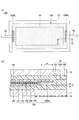
- FIG. 1 is a diagram illustrating the laminated glass according to the first embodiment, and FIG. 1A schematically shows a state in which the laminated glass is attached to the vehicle and visually recognized from the outside of the vehicle interior to the inside of the vehicle.
- FIG. 1B is a partially enlarged cross-sectional view taken along the line AA of FIG. 1A.
- the laminated glass 10 is a laminated glass for a vehicle having a glass plate 11, a glass plate 12, an interlayer film 13, a shielding layer 14, and a dimming element 15.
- the shielding layer 14 is provided as needed.
- the laminated glass 10 may have a curved shape in the longitudinal direction and the lateral direction.
- the laminated glass 10 may have a shape curved only in the longitudinal direction or a shape curved only in the lateral direction.
- the laminated glass 10 has a rectangular shape, but the planar shape of the laminated glass 10 is not limited to a rectangular shape, and may be any shape including a trapezoidal shape.
- the laminated glass 10 can be applied to, for example, roof glass, rear glass, rear side glass, rear quarter glass, roof glass, extra glass, etc. for vehicles.
- the extra glass is glass attached to the rear side of the vehicle in order to improve the rear visibility of the driver of the vehicle.
- the glass plate 11 is a glass plate inside the vehicle that becomes the inside of the vehicle when the laminated glass 10 is attached to the vehicle.
- the glass plate 12 is a vehicle outer glass plate that becomes the outer side of the vehicle when the laminated glass 10 is attached to the vehicle.
- the glass plates 11 and 12 may have a predetermined curvature.
- the glass plate 11 and the glass plate 12 are a pair of glass plates facing each other, and the interlayer film 13 and the dimming element 15 are located between the pair of glass plates.
- the glass plate 11 and the glass plate 12 are fixed with the interlayer film 13 and the light control element 15 sandwiched between them.
- the interlayer film 13 is a film that joins the glass plate 11 and the glass plate 12.
- the interlayer film 13 is located between, for example, the intermediate film 131 bonded to the glass plate 11, the intermediate film 132 bonded to the glass plate 12, and the intermediate film 131 and the intermediate film 132, and surrounds the outer periphery of the dimming element 15. It has a frame-shaped interlayer film 133.
- the interlayer film 13 may have an interlayer film 131 to be bonded to the glass plate 11 and an intermediate film 132 to be bonded to the glass plate 12, and may not have the interlayer film 133. Even if the interlayer film 133 is not provided, the outer periphery of the dimming element 15 is surrounded by the interlayer film 131 and / or 132 during crimping in the manufacturing process of the laminated glass 10.
- the interlayer film 13 When it is not necessary to distinguish between the interlayer films 131, 132, and 133, they are simply referred to as the interlayer film 13. Details of the glass plate 11, the glass plate 12, and the interlayer film 13 will be described later.
- the shielding layer 14 is an opaque layer, and can be provided in a strip shape along the peripheral edge of the laminated glass 10, for example.
- the shielding layer 14 is, for example, an opaque (eg, black) colored ceramic layer.
- the shielding layer 14 may be a colored interlayer film or a colored film having a light-shielding property, or a combination of the colored interlayer film and the colored ceramic layer.
- the colored film may be integrated with an infrared reflective film or the like.
- the presence of the opaque shielding layer 14 on the laminated glass 10 can suppress deterioration of the resin such as urethane that holds the peripheral edge of the laminated glass 10 on the vehicle body due to ultraviolet rays. Further, the electrodes electrically connected to the dimming element 15 and the electrode take-out wiring can be concealed so as to be difficult to see from the outside of the vehicle and / or the inside of the vehicle.
- the shielding layer 14 can be formed, for example, by applying a ceramic color paste containing a meltable glass frit containing a black pigment on a glass plate by screen printing or the like and firing it, but the shielding layer 14 is not limited thereto.
- the shielding layer 14 may be formed by, for example, applying an organic ink containing a black or dark pigment on a glass plate by screen printing or the like and drying it.
- the shielding layer 14 is provided on the peripheral edge of the inner surface of the glass plate 11.
- the shielding layer 14 may be provided on the peripheral edge of the vehicle inner surface of the glass plate 12, if necessary, the peripheral edge of the vehicle inner surface of the glass plate 11, and the vehicle inner surface of the glass plate 12. It may be provided on both edges of the glass.
- the dimming element 15 is an element capable of switching the light transmittance of the laminated glass 10.
- the dimming element 15 may be arranged on substantially the entire laminated glass 10 or only a part thereof, if necessary.
- the planar shape of the dimming element 15 is, for example, a rectangle smaller than the planar shape of the laminated glass 10. In the example of FIG. 1, the peripheral edge of the dimming element 15 is located at a position where it overlaps with the shielding layer 14 in a plan view.
- the light control element 15 includes a base material 151, a conductive film 152, a light control layer 153, a conductive film 154, a base material 155, and an electrode 156, and is enclosed in an interlayer film 13. That is, the dimming element 15 is covered with an interlayer film 13.
- the dimming element 15 is, for example, in the form of a film.
- the thickness of the dimming element 15 is, for example, 0.05 mm or more and 0.5 mm or less, preferably 0.1 mm or more and 0.4 mm or less.
- An electrode take-out wiring 16 for connecting the electrode 156 to an external circuit is connected to the electrode 156 of the dimming element 15.
- the base materials 151 and 155 are transparent resin layers.
- the thicknesses of the base materials 151 and 155 are, for example, 5 ⁇ m or more and 500 ⁇ m or less, preferably 10 ⁇ m or more and 200 ⁇ m or less, and more preferably 50 ⁇ m or more and 150 ⁇ m or less.
- the substrates 151 and 155 include, for example, polyethylene terephthalate, polyethylene naphthalate, polyamide, polyether, polysulphon, polyethersulphon, polycarbonate, polyarylate, polyetherimide, polyetheretherketone, polyimide, aramid, polybutylene terephthalate, and the like. It can be formed by any one selected from the group of triacetyl cellulose, polyurethane, and cycloolefin polymer.
- the conductive film 152 is formed on the surface of the base material 151 on the glass plate 12 side, and is in contact with the surface of the light control layer 153 on the glass plate 11 side.
- the conductive film 154 is formed on the surface of the base material 155 on the glass plate 11 side, and is in contact with the surface of the light control layer 153 on the glass plate 12 side. That is, the conductive films 152 and 154 are a pair of conductive films sandwiching the light control layer 153.
- TCO transparent conductive oxide
- ITO tin-added indium oxide
- AZO aluminum-added zinc oxide
- ITO tin-added indium oxide
- ITO tin-doped indium oxide
- AZO aluminum-added zinc oxide
- indium-added cadmium oxide examples include, but are not limited to, tin-added indium oxide (ITO: tin-doped indium oxide), aluminum-added zinc oxide (AZO: aluminum doped zinc oxide), and indium-added cadmium oxide.
- conductive films 152 and 154 transparent conductive polymers such as poly (3,4-ethylenedioxythiophene) (PEDOT) or poly (4,4-dioctylcyclopentadithiophene) can also be preferably used.
- transparent conductive polymers such as poly (3,4-ethylenedioxythiophene) (PEDOT) or poly (4,4-dioctylcyclopentadithiophene) can also be preferably used.
- PEDOT poly (3,4-ethylenedioxythiophene)
- poly (4,4-dioctylcyclopentadithiophene) poly(1,4-dioctylcyclopentadithiophene)
- a laminated film of a metal layer and a dielectric layer silver nanowires, a metal mesh of silver or copper and the like can also be preferably used.
- the conductive films 152 and 154 can be formed by using, for example, a physical vapor deposition method (PVD: Physical Vapor Deposition) such as a sputtering method, a vacuum vapor deposition method, or an ion plating method.
- PVD Physical vapor deposition
- the conductive films 152 and 154 may be formed by using a chemical vapor deposition (CVD) method or a wet coating method.
- the dimming layer 153 is sandwiched between the base material 151 on which the conductive film 152 is formed and the base material 155 on which the conductive film 154 is formed.
- the dimming layer 153 for example, any one or more selected from the group of suspended particle device (SPD: Suspended Particle Device), guest host liquid crystal, photochromic, electrochromic, and electrokinetic can be selected.
- SPD suspended particle device
- guest host liquid crystal for example, any one or more selected from the group of suspended particle device (SPD: Suspended Particle Device), guest host liquid crystal, photochromic, electrochromic, and electrokinetic can be selected.
- the dimming element 15 is arranged so as to face each other, the base material 151 on which the conductive film 152 is formed, the base material 155 on which the conductive film 154 is formed, and the conductive film 152 and the conductive film 154 facing each other. It has a dimming layer 153 composed of any one or more selected from the group of suspended particle device, guest host liquid crystal, photochromic, electrochromic, and electrokinetic arranged between and.
- the suspended particle device is a general SPD film configured by sandwiching a polymer layer containing suspended particles that can be oriented by applying a voltage between two substrates coated with a conductive film inside. Can be used.
- Such an SPD film has a high visible light transmittance and a high transparency by orienting the suspended particles in the polymer layer by turning on the power switch and applying a voltage between the transparent conductive films. Become. When the power switch is off, the suspended particles in the polymer layer are not oriented, the visible light transmittance is low, and the transparency is low.
- the SPD film for example, a commercially available product such as LCF-1103DHA (trade name, manufactured by Hitachi Kasei Co., Ltd.) can be used. Since such a commercially available product is supplied in a predetermined size, it is cut into a desired size before use.
- the thickness of the SPD film is not particularly limited, but is preferably 0.1 mm or more and 0.4 mm or less from the viewpoint of handleability and availability.
- the electrode 156 is arranged at a position overlapping the shielding layer 14 in a plan view, for example.
- the electrode 156 is inserted between the conductive film 152 and the conductive film 154.
- the first main surface and the second main surface of the electrode 156 are in contact with a film other than the interlayer film 13.
- the first main surface of the electrode 156 is a surface facing the glass plate 11 side.
- the second main surface of the electrode 156 is a surface opposite to the first main surface and faces the glass plate 12 side.
- the electrodes 156 are electrically separated vertically through an insulating layer (not shown), one of the upper and lower electrodes is electrically connected to the conductive film 152, and the other upper and lower electrodes are electrically connected to the conductive film 154. , The conductive films 152 and 154 are energized to drive the dimming layer 153. That is, the first main surface of the electrode 156 is in contact with the conductive film 152, and the second main surface of the electrode 156 is in contact with the conductive film 154.
- One pole of the electrode 156 is, for example, a positive electrode, and is connected to the positive side of a power source such as a battery mounted on a vehicle via an electrode take-out wiring 16 electrically connected to one pole of the electrode 156.
- the other pole of the electrode 156 is, for example, a negative electrode, and is connected to the negative side of a power source such as a battery mounted on a vehicle via an electrode take-out wiring 16 electrically connected to the other pole of the electrode 156.
- the transmittance of the dimming layer 153 is switched according to the voltage.
- the material of the electrode 156 is not particularly limited as long as it is a conductive material, and examples thereof include a metal material.
- metal materials include gold, silver, copper, aluminum, tungsten, platinum, palladium, nickel, cobalt, titanium, iridium, zinc, magnesium, tin and the like. Further, these metals may be plated or may be composed of a composite with an alloy or a resin.
- a copper ribbon, a flat braided copper wire, or an FPC Flexible Printed Circuit
- the copper ribbon or flat braided conductor may be plated with a metal other than copper.
- the electrode 156 can be bonded to the conductive films 152 and 154 by any of a conductive adhesive material (conductive adhesive layer), an anisotropic conductive film, and solder. Further, the electrode 156 may be brought into direct contact with the conductive films 152 and 154 without using a conductive adhesive material, an anisotropic conductive film, or solder. Alternatively, the electrode 156 may be formed by a printing method such as screen printing, inkjet printing, offset printing, flexographic printing, or gravure printing.
- the electrode 156 has a length and shape necessary and sufficient for energizing the dimming element 15.
- the shape of the electrode 156 is not particularly limited, but is generally substantially rectangular. Since the electrode 156 needs to be concealed by the shielding layer 14, for example, the glass plates 11 and 12 are placed on either end (the short side of either one) of the dimming element 15 in the longitudinal direction. It is arranged substantially parallel to the peripheral edge.
- the electrode 156 is preferably arranged 10 mm or more inward from the peripheral edges of the glass plates 11 and 12, and more preferably 15 mm or more inward. With such an arrangement, it is possible to reduce the possibility that moisture invades from the peripheral edges of the glass plates 11 and 12 and causes corrosion of the electrodes 156 and short circuits between different potentials.
- the length of the electrode 156 is not particularly limited, but is preferably 5 mm or more in consideration of ensuring a sufficient energizing function and improving workability. As will be described later, a plurality of electrodes 156 may exist, and they may be arranged on the same side or may be arranged so as to face the opposite sides.
- the handleability is improved, and the contact area with the conductive films 152 and 154 can be sufficiently secured, so that the function as an electrode is fully exhibited. It will be possible.
- the shielding layer 14 facilitates concealment and improves the design.
- the thickness of the electrode 156 is preferably 0.05 mm to 0.4 mm.
- the thickness of the electrode 156 is preferably 0.05 mm to 0.4 mm.
- the dimming element 15 has an electrode forming portion in which the electrode 156 is formed and an electrode non-forming portion in which the electrode 156 is not formed.
- the electrode forming portion is a portion that overlaps with the electrode 156 in a plan view, and does not include an inclined portion (a portion whose thickness decreases as the distance from the electrode 156 increases) around the electrode 156.
- all parts other than the electrode forming part are electrode non-forming parts.
- the dimming element 15 includes a first reference surface 158 and a second reference surface 159 that serve as a reference when defining the height of the electrode forming portion.
- the first reference surface 158 is a non-electrode forming portion and is a surface in contact with the interlayer film 131 on the glass plate 11 side in a portion where the thickness of the dimming element 15 is substantially constant.
- the height of the electrode forming portion when the first reference surface 158 is used as a reference is lower than the first reference surface 158 when the glass plate 11 side is in the positive direction with respect to the first reference surface 158.
- the problem is the magnitude of the absolute value of the height of the electrode forming portion. Therefore, hereinafter, the average value of the heights of the electrode forming portions with respect to the first reference plane 158 is the average of the absolute values of the heights of the electrode forming portions with respect to the first reference plane 158. Means a value.
- the height of the electrode forming portion when the second reference surface 159 is used as a reference is lower than the second reference surface 159 when the glass plate 12 side is in the positive direction with respect to the second reference surface 159.
- the problem is the magnitude of the absolute value of the height of the electrode forming portion. Therefore, hereinafter, the average value of the heights of the electrode forming portions with respect to the second reference plane 159 is the average of the absolute values of the heights of the electrode forming portions with respect to the second reference plane 159. Means a value.
- the portion where the thickness of the dimming element 15 is substantially constant is defined as an inclined portion around the electrode 156 in FIG. 1 (b) in the electrode non-forming portion and a side wall of the electrode 156 A 2 in FIG. 3 described later. This is a portion excluding the exposed recess 15x. Therefore, the inclined portion around the electrode 156 and the recess 15x described later are not included in the first reference surface 158.
- the second reference surface 159 is a non-electrode forming portion and is a surface in contact with the interlayer film 132 on the glass plate 12 side in a portion where the thickness of the dimming element 15 is substantially constant. Therefore, the inclined portion around the electrode 156 is not included in the second reference plane 159.
- t1 indicates an average value [mm] of the height (absolute value) of the electrode forming portion when the first reference surface 158 of the dimming element 15 is used as a reference.
- t2 indicates an average value [mm] of the height (absolute value) of the electrode forming portion when the second reference surface 159 of the dimming element 15 is used as a reference.
- w indicates the length [mm] of the electrode 156 in the lateral direction.
- t1, t2, and w are 0 ⁇ w ⁇ t1 ⁇ 0.7 and 0 ⁇ w ⁇ t2 ⁇ 0.7 (however, 3 ⁇ w ⁇ 20).
- -It is determined to satisfy the equation (1).
- T1 and w are determined so that the value [mm 2 ] multiplied by [mm] is 0 [mm 2 ] or more and 0.7 [mm 2] or less.
- t2 and w are determined so as to be 0 [mm 2 ] or more and 0.7 [mm 2] or less.
- t1 and t2 are determined so as to satisfy the equation (1) for the average value of w. To.
- a laminated body in which the glass plate 11, the interlayer film 131, the dimming element 15, the interlayer film 133, the intermediate film 132, and the glass plate 12 are sequentially laminated is prepared. Then, the prepared laminate is placed in, for example, a rubber bag, and the inside of the rubber bag is heated while being sucked under reduced pressure (deaeration treatment) and pre-crimped. If necessary, the pre-crimped laminate is placed in, for example, an autoclave. Heat and pressurize the bag to perform main bonding (main crimping).
- the degassing property deteriorates in the process of manufacturing the laminated glass 10, and appearance defects such as foaming and air residue occur.
- the thickness deviation around the electrode is reduced. Therefore, in the process of manufacturing the laminated glass 10, it is possible to suppress poor deaeration around the electrodes (improve the exhaustability of residual air), and it is possible to prevent the occurrence of appearance defects such as foaming and residual air.
- t1, t2, and w satisfy the formula (1), and t1 ⁇ 0.15 [mm] and t2 ⁇ 0.15 [mm]. By satisfying this requirement, in the step of manufacturing the laminated glass 10, it is possible to further suppress the degassing defect around the electrode.
- the glass plate 11, the glass plate 12, and the interlayer film 13 will be described in detail.
- the glass plates 11 and 12 may be inorganic glass or organic glass.
- the inorganic glass for example, soda lime glass, aluminosilicate glass, borosilicate glass, non-alkali glass, quartz glass and the like are used without particular limitation.
- the glass plate 12 located on the outside of the laminated glass 10 is preferably inorganic glass from the viewpoint of scratch resistance, and is preferably soda lime glass from the viewpoint of moldability.
- the glass plate 11 and the glass plate 12 are soda lime glass, clear glass, green glass containing an iron component in a predetermined amount or more, and UV-cut green glass can be preferably used.
- the inorganic glass may be either untempered glass or tempered glass.
- Untempered glass is made by molding molten glass into a plate shape and slowly cooling it. Tempered glass is formed by forming a compressive stress layer on the surface of untempered glass.
- the tempered glass may be either physically tempered glass such as wind-cooled tempered glass or chemically tempered glass.
- physically tempered glass for example, a glass plate uniformly heated in bending molding is rapidly cooled from a temperature near the softening point, or by an operation other than slow cooling, the temperature difference between the glass surface and the inside of the glass causes the glass surface to become.
- the glass surface can be strengthened.
- the glass surface can be strengthened by generating compressive stress on the glass surface by an ion exchange method or the like.
- a glass that absorbs ultraviolet rays or infrared rays may be used, and more preferably, a glass plate colored to such an extent that the transparency is not impaired may be used.
- examples of the material of organic glass include polycarbonate, for example, acrylic resin such as polymethylmethacrylate, and transparent resin such as polyvinyl chloride and polystyrene.
- the shapes of the glass plates 11 and 12 are not particularly limited to a rectangular shape, and may be a shape processed into various shapes and curvatures. Gravity molding, press molding, roller molding and the like are used for bending molding of the glass plates 11 and 12.
- the molding method of the glass plates 11 and 12 is not particularly limited, but for example, in the case of inorganic glass, a glass plate molded by a float method or the like is preferable.
- the thinnest portion of the glass plate 12 is preferably 1.1 mm or more and 3 mm or less.
- the strength such as stepping stone resistance is sufficient, and when it is 3 mm or less, the mass of the laminated glass 10 does not become too large, which is preferable in terms of fuel efficiency of the vehicle. ..
- the thinnest portion of the glass plate 12 is more preferably 1.8 mm or more and 2.8 mm or less, further preferably 1.8 mm or more and 2.6 mm or less, and further preferably 1.8 mm or more and 2.2 mm or less. More preferably, it is 8 mm or more and 2.0 mm or less.
- the thickness of the glass plate 11 is preferably 0.3 mm or more and 2.3 mm or less.
- the handleability is good, and when it is 2.3 mm or less, the mass does not become too large.
- the glass plates 11 and 12 may have a flat plate shape or a curved shape.
- the glass plates 11 and 12 have a curved shape and the thickness of the glass plates 11 is not appropriate, when two glass plates 11 and 12 having a particularly deep bend are formed, a mismatch occurs between the two shapes. , It greatly affects the glass quality such as residual stress after crimping.
- the plate thickness of the glass plate 11 is set to 0.3 mm or more and 2.3 mm or less.
- Setting the plate thickness of the glass plate 11 to 0.3 mm or more and 2.3 mm or less is particularly effective for maintaining the glass quality in deeply bent glass.
- the thickness of the glass plate 11 is more preferably 0.5 mm or more and 2.1 mm or less, and further preferably 0.7 mm or more and 1.9 mm or less. Within this range, the above effect becomes even more remarkable.
- a coating having a water-repellent, ultraviolet or infrared blocking function, or a coating having low reflection characteristics and low radiation characteristics may be provided on the outside of the glass plate 11 and / or 12. Further, a film having ultraviolet or infrared ray blocking, low radiation characteristics, visible light absorption, coloring or the like may be provided on the side of the glass plate 11 and / or 12 in contact with the interlayer film 13.
- the glass plates 11 and 12 are curved inorganic glass, the glass plates 11 and 12 are bent and molded after being molded by the float method and before being bonded by the interlayer film 13. Bending molding is performed by softening the glass by heating. The heating temperature of the glass during bending is approximately 550 ° C to 700 ° C.
- thermoplastic resin is often used as the interlayer film 13, and for example, a plasticized polyvinyl acetal resin, a plasticized polyvinyl chloride resin, a saturated polyester resin, a plasticized saturated polyester resin, a polyurethane resin, and a plasticized polyurethane resin are used.
- thermoplastic resins conventionally used for this type of application such as resins, ethylene-vinyl acetate copolymer resins, ethylene-ethyl acrylate copolymer resins, cycloolefin polymer resins, and ionomer resins.
- the resin composition containing the modified block copolymer hydride described in Japanese Patent No. 6065221 can also be preferably used.
- plasticized polyvinyl acetal-based resins have an excellent balance of various performances such as transparency, weather resistance, strength, adhesive strength, penetration resistance, impact energy absorption, moisture resistance, heat insulation, and sound insulation. Is preferably used. These thermoplastic resins may be used alone or in combination of two or more. "Plasticization" in the plasticized polyvinyl acetal-based resin means that it is plasticized by adding a plasticizer. The same applies to other plasticized resins.
- the dimming element 15 when the dimming element 15 is enclosed in the interlayer film 13, it may be deteriorated by a specific plasticizer depending on the type of the object to be enclosed.
- a resin that does not substantially contain the plasticizer Is preferably used. That is, it may be preferable that the interlayer film 13 does not contain a plasticizer.
- the resin containing no plasticizer include an ethylene-vinyl acetate copolymer resin.
- the polyvinyl acetal resin is a polyvinyl formal resin obtained by reacting polyvinyl alcohol (hereinafter, may also be referred to as “PVA” if necessary) with formaldehyde, and a narrow sense obtained by reacting PVA with acetaldehyde.
- Polyvinyl butyral resin obtained by reacting PVA with n-butylaldehyde hereinafter, may be referred to as "PVB” if necessary
- PVB is preferable because it has an excellent balance of various performances such as strength, adhesive strength, penetration resistance, impact energy absorption, moisture resistance, heat insulation, and sound insulation.
- These polyvinyl acetal-based resins may be used alone or in combination of two or more.
- the material forming the interlayer film 13 is not limited to the thermoplastic resin. Further, the interlayer film 13 may contain functional particles such as an infrared absorber, an ultraviolet absorber, and a luminescent agent. Further, the interlayer film 13 may have a colored portion called a shade band.
- the film thickness of the interlayer film 13 is preferably 0.5 mm or more at the thinnest part. When the film thickness of the thinnest portion of the interlayer film 13 is 0.5 mm or more, the impact resistance required for the laminated glass 10 is sufficient.
- the film thickness of the interlayer film 13 is preferably 3 mm or less at the thickest portion. When the maximum value of the film thickness of the interlayer film 13 is 3 mm or less, the mass of the laminated glass 10 does not become too large.
- the maximum value of the film thickness of the interlayer film 13 is more preferably 2.8 mm or less, and further preferably 2.6 mm or less.
- the interlayer film 13 may have four or more layers. For example, by forming an interlayer film from four or more layers and making the shear modulus of any layer excluding the layers on both sides smaller than the shear modulus of the layers on both sides by adjusting a plasticizer or the like, the laminated glass 10 is formed. Sound insulation can be improved. In this case, the shear modulus of the layers on both sides may be the same or different.
- the interlayer films 131, 132, and 133 contained in the interlayer film 13 are all formed of the same material, but a part or all of the interlayer films 131, 132, and 133 are formed of different materials. May be good.
- the material may have a shear modulus smaller than that of the interlayer films 131 and 132.
- the shear modulus of the interlayer film 133 is smaller than the shear modulus of the interlayer films 131 and 132, the sound insulation of the laminated glass 10 can be improved.
- the shear modulus of the interlayer film 132 is smaller than the shear modulus of the interlayer film 131 and 133, the sound insulation of the laminated glass 10 can be improved.
- the above resin material to be an interlayer film is appropriately selected and extruded in a heat-melted state using an extruder.
- the extrusion conditions such as the extrusion speed of the extruder are set to be uniform.
- the interlayer film 13 is completed by stretching the extruded resin film, for example, as necessary, in order to give curvature to the upper side and the lower side according to the design of the laminated glass 10.
- the total thickness of the laminated glass 10 is preferably 2.8 mm or more and 10 mm or less. When the total thickness of the laminated glass 10 is 2.8 mm or more, sufficient rigidity can be secured. Further, when the total thickness of the laminated glass 10 is 10 mm or less, sufficient transmittance can be obtained and haze can be reduced.
- the plate deviation between the glass plate 11 and the glass plate 12 is preferably 1.5 mm or less, and more preferably 1 mm or less.
- the plate deviation between the glass plate 11 and the glass plate 12 is, that is, the amount of deviation between the end portion of the glass plate 11 and the end portion of the glass plate 12 in a plan view.
- the plate deviation between the glass plate 11 and the glass plate 12 is 1.5 mm or less on at least one side of the laminated glass 10, it is preferable in that the appearance is not impaired. It is more preferable that the plate deviation between the glass plate 11 and the glass plate 12 is 1.0 mm or less on at least one side of the laminated glass 10 in that the appearance is not impaired.
- an interlayer film 13 and a dimming element 15 are sandwiched between the glass plate 11 and the glass plate 12 to form a laminated body. Then, for example, this laminate is placed in a rubber bag and bonded at a temperature of about 70 ° C. to 110 ° C. in a vacuum having a gauge pressure of ⁇ 65 kPa to ⁇ 100 kPa.
- the heating conditions, temperature conditions, and laminating method are appropriately selected in consideration of the properties of the dimming element 15, for example, so as not to deteriorate during laminating.
- a laminated glass 10 having more excellent durability can be obtained.
- this heating and pressurizing step may not be used in consideration of the simplification of the step and the characteristics of the material to be sealed in the laminated glass 10.
- the glass plate 11 and the glass plate 12 in addition to the interlayer film 13 and the dimming element 15, heating wire, infrared reflection, light emission, power generation, dimming, touch panel, visible light, as long as the effect of the present application is not impaired.
- It may have a film or device having functions such as reflection, scattering, decoration, and absorption.
- the surface of the laminated glass 10 may have a film having functions such as anti-fog, water-repellent, heat-shielding, and low reflection.
- a film having functions such as heat shielding and heat generation may be provided on the outer surface of the glass plate 11 and the inner surface of the glass plate 12.
- the thickness deviation around the electrode is reduced. Therefore, in the process of manufacturing the laminated glass 10, it is possible to suppress poor deaeration around the electrodes (improve the exhaustability of residual air), and it is possible to prevent the occurrence of appearance defects such as foaming and residual air.
- Modification 1 of the first embodiment shows an example of a laminated glass provided with a dimming element having an electrode structure different from that of the first embodiment.
- the description of the same components as those of the above-described embodiment may be omitted.
- FIG. 2 is a diagram illustrating the laminated glass according to the first modification of the first embodiment, and FIG. 2A schematically shows a state in which the laminated glass is attached to the vehicle and visually recognized from the outside of the vehicle interior to the inside of the vehicle. ing.
- FIG. 2B is a partially enlarged cross-sectional view taken along the line BB of FIG. 2A.
- the laminated glass 10A is different from the laminated glass 10 (see FIG. 1) in that the dimming element 15 is replaced with the dimming element 15A.
- the dimming element 15A differs from the dimming element 15 having one electrode 156 (see FIG. 1) in that it has a pair of electrodes 156A 1 and 156A 2.
- the configuration of the dimming element 15A other than the electrodes 156A 1 and 156A 2 is the same as that of the dimming element 15.
- the electrodes 156A 1, electrode lead-out wiring 16 1 for connecting the electrodes 156A 1 and the external circuit is connected. Further, the electrodes 156A 2, electrode lead wires 16 2 for connecting the electrode 156A 2 and the external circuit are connected.
- the electrodes 156A 1 and 156A 2 are arranged, for example, at positions overlapping the shielding layer 14 in a plan view.
- the 156A 1 and 156A 2 are arranged in the portion where the dimming element 15A is half-cut.
- the electrode 156A 1 is arranged so that the first main surface is in contact with the surface of the conductive film 152 exposed by partially removing the base material 155, the conductive film 154, and the dimming layer 153. ..
- the second main surface of the electrode 156A 1 is in contact with the interlayer film 132.
- the electrodes 156A 2 are arranged so that the second main surface is in contact with the surface of the conductive film 154 exposed by partially removing the base material 151, the conductive film 152, and the light control layer 153.
- the first main surface of the electrode 156A 2 is in contact with the interlayer film 131.
- the first main surface of the electrodes 156A 1 and 156A 2 is a surface facing the glass plate 11 side.
- the second main surface of the electrodes 156A 1 and 156A 2 is a surface opposite to the first main surface and faces the glass plate 12 side.
- Electrodes 156A 1 is, for example, a positive electrode, via the electrode lead wires 16 1, is connected to the positive side of the power supply such as a battery mounted on the vehicle.
- the electrode 156A 2 is a negative electrode for example, via the electrode lead wire 16 2 is connected to the negative side of the power supply such as a battery mounted on the vehicle.
- the transmittance of the dimming layer 153 is switched according to the voltage.
- the materials of the electrodes 156A 1 and 156A 2 , the bonding method with the conductive film, the length, the width, and the thickness are the same as those exemplified for the electrode 156 in the first embodiment.
- the peripheral portions of the glass plates 11 and 12 are formed on both ends (both short sides) of the dimming element 15A in the longitudinal direction. Arranged substantially parallel to (edge).
- the electrodes 156A 1 and 156A 2 are preferably arranged 10 mm or more inward from the peripheral edges of the glass plates 11 and 12, and more preferably 15 mm or more inward. With such an arrangement, it is possible to reduce the possibility that moisture invades from the peripheral edges of the glass plates 11 and 12 and causes corrosion of the electrodes 156A 1 and 156A 2 and a short circuit between different potentials.
- t1, t2, and w are determined to satisfy the formula (1).
- t2 0 because there is no step on the second reference surface 159 side.
- the length of the electrode 156A 1 in the lateral direction is w1
- the length of the electrode 156A 2 in the lateral direction is w2
- w1 ⁇ w2 each of w1 and w2 satisfies the equation (1).
- connection between the electrode and the conductive film is not particularly limited, and may be an insertion type electrode as shown in FIG. 1 or a half-cut type electrode as shown in FIG.
- the thickness deviation around the electrode is reduced by satisfying the equation (1) with t1, t2, and w of the laminated glass. Therefore, in the process of manufacturing the laminated glass, it is possible to suppress poor deaeration around the electrodes (improve the exhaust property of residual air), and it is possible to prevent the occurrence of appearance defects such as foaming and residual air.
- t1, t2, and w satisfy the formula (1) and t1 ⁇ 0.15 [mm]. By satisfying this requirement, it is possible to further suppress poor degassing around the electrodes in the step of manufacturing the laminated glass 10A.
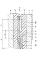
- FIG. 3 is a diagram illustrating a recess formed in the electrode non-forming portion.
- E 1 shows an electrode forming portion
- E 2 shows an electrode non-forming portion.
- the electrode forming portion E of the electrode non-forming portion E 2 is formed in a vertical cross section along a direction parallel to the lateral direction of the electrode 156A 2 .
- the end of the 1 side, the recess 15x for exposing the sidewalls of the electrode 156A 2 are formed (the same applies to the end portion of the electrode 156A 1 side).
- Recess 15x is recessed from the first reference surface 158 side of the non-electrode portion E 2 to the conductive film 154 side, bottom is formed by the conductive film 154.
- the height t3 of the first side wall of the recess 15x which is the side wall of the electrode 156A 2 , and the electrode non-forming portion E 2 side facing the first side wall.
- the distance wx between the first side wall and the second side wall is short in terms of improving degassing property.
- the distance wx between the first side wall and the second side wall is 5 mm or less, the effect on degassing is small, and when the distance wx is 3 mm or less, the effect on degassing is even smaller. If it is 2 mm or less, it is preferable because it has less influence on degassing.
- the height t3 of the first side wall of the recess 15x which is the side wall of the electrode 156A 2 , and the electrode non-forming portion E 2 side facing the first side wall.
- the height t4 of the second side wall of the above is larger than 0.15 mm.
- the distance wx between the first side wall and the second side wall is short in terms of improving degassing property.
- the distance wx between the first side wall and the second side wall is 5 mm or less, the effect on degassing is small, and when the distance wx is 3 mm or less, the effect on degassing is even smaller. If it is 2 mm or less, it is preferable because it has less influence on degassing.
- the second modification of the first embodiment shows an example of a laminated glass provided with a dimming element having an electrode arrangement different from that of the first modification of the first embodiment.
- the description of the same component as that of the above-described embodiment may be omitted.
- FIG. 4 is a plan view illustrating the laminated glass according to the second modification of the first embodiment, and schematically shows a state in which the laminated glass is attached to the vehicle and visually recognized from the outside of the vehicle interior to the inside of the vehicle interior.
- the laminated glass 10B is different from the laminated glass 10A (see FIG. 2) in that the dimming element 15A is replaced with the dimming element 15B.
- the dimming element 15B differs from the dimming element 15A (see FIG. 2) having a pair of electrodes 156A 1 and 156A 2 in that it has a pair of electrodes 156B 1 and 156B 2.
- the configuration of the dimming element 15B other than the electrodes 156B 1 and 156B 2 is the same as that of the dimming element 15A.
- the electrode 156B 1, the electrode take-out wiring 16 1 for connecting the electrode 156B 1 and the external circuit is connected. Further, the electrode 156B 2, electrode lead wires 16 2 for connecting the electrode 156B 2 and the external circuit is connected.
- the materials of the electrodes 156B 1 and 156B 2 , the bonding method with the conductive film, the length, the width, and the thickness are the same as those exemplified for the electrode 156 in the first embodiment.
- a glass plate is attached to either end (the short side of either one) of the dimming element 15B in the longitudinal direction. It is arranged substantially parallel to the peripheral edges (edges) of 11 and 12.
- the electrodes 156B 1 and 156B 2 are preferably arranged 10 mm or more inward from the peripheral edges of the glass plates 11 and 12, and more preferably 15 mm or more inward. With such an arrangement, it is possible to reduce the possibility that moisture invades from the peripheral edges of the glass plates 11 and 12 and causes corrosion of the electrodes 156B 1 and 156B 2 and a short circuit between different potentials.
- t1, t2, and w are determined to satisfy the formula (1).
- t2 0 because there is no step on the second reference surface 159 side.
- the length of the electrode 156B 1 in the lateral direction is w1
- the length of the electrode 156B 2 in the lateral direction is w2
- w1 ⁇ w2 each of w1 and w2 satisfies the equation (1).
- t1, t2, and w satisfy the formula (1) and t1 ⁇ 0.15 [mm]. By satisfying this requirement, it is possible to further suppress poor degassing around the electrodes in the step of manufacturing the laminated glass 10B.
- the laminated glass 10B has electrodes 156B 1 and B 2 at the end of the non-electrode formed portion on the electrode forming portion side in a vertical cross section along a direction parallel to the lateral direction of the electrode. A recess is formed that exposes the side wall.
- the distance between the first side wall and the second side wall is 5 mm or less. If it is, it is preferable in that the influence on degassing is small, if it is 3 mm or less, it is preferable in that the influence on degassing is further small, and if it is 2 mm or less, it is preferable in that the influence on degassing is further small.
- both the height of the first side wall and the height of the second side wall of the recess are larger than 0.15 mm, if the distance between the first side wall and the second side wall is 5 mm or less, the effect on degassing is affected. It is preferable in that it is small, and it is preferable that it is 3 mm or less because it has a smaller effect on degassing, and it is preferable that it is 2 mm or less because it has a smaller effect on degassing.
- the pair of electrodes may be arranged so as to face each other on the peripheral edges of the glass plates 11 and 12, or are arranged in a row on the same side of the peripheral edges of the glass plates 11 and 12 at predetermined intervals. May be done.
- the thickness deviation around the electrode is reduced by satisfying the equation (1) with t1, t2, and w of the laminated glass. Therefore, in the process of manufacturing the laminated glass, it is possible to suppress poor deaeration around the electrodes (improve the exhaust property of residual air), and it is possible to prevent the occurrence of appearance defects such as foaming and residual air.
- Modification 3 of the first embodiment shows another example of laminated glass provided with a dimming element having an electrode arrangement different from that of modification 1 of the first embodiment.
- the description of the same component as that of the above-described embodiment may be omitted.
- FIG. 5 is a plan view illustrating the laminated glass according to the modified example 3 of the first embodiment, and schematically shows a state in which the laminated glass is attached to the vehicle and visually recognized from the outside of the vehicle interior to the inside of the vehicle interior.
- the laminated glass 10C is different from the laminated glass 10A (see FIG. 2) in that the dimming element 15A is replaced with the dimming element 15C.
- Light control device 15C is that it has a pair of electrodes 156C 1 and 156C 2 are, different from the light control element 15A having a pair of electrodes 156A 1 and 156A 2 (see FIG. 2).
- the configuration of the dimming element 15C other than the electrodes 156C 1 and 156C 2 is the same as that of the dimming element 15A.
- the electrode 156C 1, electrode lead-out wiring 16 1 for connecting the electrode 156C 1 and an external circuit is connected. Further, the electrode 156C 2, electrode lead wires 16 2 for connecting the electrode 156C 2 and the external circuit is connected.
- the materials of the electrodes 156C 1 and 156C 2 , the bonding method with the conductive film, the length, the width, and the thickness are the same as those exemplified for the electrode 156 in the first embodiment.
- the electrodes 156C 1 and 156C 2 need to be concealed by the shielding layer 14, for example, glass is attached to either end (the long side of either one) of the dimming element 15C in the lateral direction. It is arranged substantially parallel to the peripheral edges (edges) of the plates 11 and 12.
- the electrodes 156C 1 and 156C 2 are preferably arranged 10 mm or more inward from the peripheral edges of the glass plates 11 and 12, and more preferably 15 mm or more inward. With such an arrangement, it is possible to reduce the possibility that moisture invades from the peripheral edges of the glass plates 11 and 12 and causes corrosion of the electrodes 156C 1 and 156C 2 and a short circuit between different potentials.
- t1, t2, and w are determined to satisfy the formula (1).
- t2 0 because there is no step on the second reference surface 159 side.
- the length of the electrode 156C 1 in the lateral direction is w1
- the length of the electrode 156C 2 in the lateral direction is w2
- w1 ⁇ w2 each of w1 and w2 satisfies the equation (1).
- t1, t2, and w satisfy the formula (1) and t1 ⁇ 0.15 [mm]. By satisfying this requirement, it is possible to further suppress poor degassing around the electrodes in the step of manufacturing the laminated glass 10C.
- the laminated glass 10C has electrodes 156C 1 and C 2 at the end of the non-electrode forming portion on the electrode forming portion side in a vertical cross section along a direction parallel to the lateral direction of the electrode. A recess is formed that exposes the side wall.
- the distance between the first side wall and the second side wall is 5 mm or less. If it is, it is preferable in that the influence on degassing is small, if it is 3 mm or less, it is preferable in that the influence on degassing is further small, and if it is 2 mm or less, it is preferable in that the influence on degassing is further small.
- both the height of the first side wall and the height of the second side wall of the recess are larger than 0.15 mm, if the distance between the first side wall and the second side wall is 5 mm or less, the effect on degassing is affected. It is preferable in that it is small, and it is preferable that it is 3 mm or less because it has a smaller effect on degassing, and it is preferable that it is 2 mm or less because it has a smaller effect on degassing.
- the pair of electrodes may be arranged so as to face each other at both ends in the longitudinal direction of the dimming element, or may be spaced apart from each other at either end in the longitudinal direction of the dimming element. They may be arranged in a row. Further, the dimming elements may be arranged in a row at a predetermined interval at any one end in the lateral direction.
- the thickness deviation around the electrode is reduced by satisfying the equation (1) with t1, t2, and w of the laminated glass. Therefore, in the process of manufacturing the laminated glass, it is possible to suppress poor deaeration around the electrodes (improve the exhaust property of residual air), and it is possible to prevent the occurrence of appearance defects such as foaming and residual air.
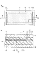
- FIG. 6 is a diagram illustrating the laminated glass according to the modified example 4 of the first embodiment, and FIG. 6A schematically shows a state in which the laminated glass is attached to the vehicle and visually recognized from the outside of the vehicle interior to the inside of the vehicle. ing.
- FIG. 6B is a partially enlarged cross-sectional view taken along the line CC of FIG. 6A.
- the laminated glass 10D differs from the laminated glass 10A (see FIG. 2) in that the dimming element 15A is replaced with the electric heating element 15D.
- the electric heating element 15D is an element capable of heating the laminated glass 10D. If necessary, the electric heating element 15D may be arranged on substantially the entire laminated glass 10D, or may be arranged only on a part of the laminated glass 10D.
- the planar shape of the electric heating element 15D is, for example, a rectangle.
- the outer edge portion of the electric heating element 15D is located, for example, at a position where it overlaps with the shielding layer 14 in a plan view.
- the electric heating element 15D is in the form of a film including a base material 155, a heat generating portion 154D, and electrodes 156D 1 and D 2, and is enclosed in an interlayer film 13. That is, the electric heating element 15D is surrounded by the interlayer film 13.
- the heat generating portion 154D can be formed from a conductive film such as gold, silver, copper, tin-doped indium oxide or the like.
- the heat generating portion 154D can be formed by using, for example, a physical vapor deposition method (PVD: Physical Vapor Deposition) such as a sputtering method, a vacuum vapor deposition method, or an ion plating method.
- PVD Physical Vapor Deposition
- the heat generating portion 154D may be formed by using a chemical vapor deposition method (CVD) or a wet coating method.
- a heating wire or a mesh-like metal may be used as the heat generating portion 154D.
- the material of the heating wire or the mesh-like metal is not particularly limited as long as it is a conductive material, and for example, at least one metal selected from the group consisting of gold, silver, copper, aluminum, nickel, and tungsten. Examples include alloys containing two or more metals selected from the group.
- the electrode 156D 1, electrode lead-out wiring 16 1 for connecting the electrode 156D 1 and the external circuit is connected. Further, the electrode 156D 2, electrode lead wires 16 2 for connecting the electrode 156D 2 to an external circuit are connected.
- the first main surfaces of the electrodes 156 D 1 and D 2 are in contact with the interlayer film 131.
- the second main surface of the electrodes 156D 1 and 156D 2 is in contact with the surface of the heat generating portion 154D.
- the first main surface of the electrodes 156D 1 and 156D 2 is a surface facing the glass plate 11 side.
- the second main surface of the electrodes 156D 1 and 156D 2 is a surface opposite to the first main surface and faces the glass plate 12 side.
- Electrode 156D 1 is, for example, a positive electrode, via the electrode lead wires 16 1, is connected to the positive side of the power supply such as a battery mounted on the vehicle. Further, the electrode 156D 2 is a negative electrode for example, via the electrode lead wire 16 2 is connected to the negative side of the power supply such as a battery mounted on the vehicle.
- the heat generating unit 154D When a voltage is supplied from a power source such as a battery to the heat generating unit 154D via the electrodes 156D 1 and 156D 2 , the amount of heat generated by the heat generating unit 154D is changed according to the voltage.
- the heat generating portion 154D When the heat generating portion 154D generates heat, the effect of eliminating the freezing of the moisture adhering to the laminated glass 10D (melting ice) and clearing the fogging (anti-fog) can be obtained.
- the materials of the electrodes 156D 1 and 156D 2 , the bonding method with the conductive film, the length, the width, and the thickness are the same as those exemplified for the electrode 156 in the first embodiment.
- the electrodes 156D 1 and 156D 2 need to be concealed by the shielding layer 14, for example, the peripheral portions of the glass plates 11 and 12 (on both short side sides) of the electric heating element 15D in the longitudinal direction (the peripheral portions of the glass plates 11 and 12). It is arranged approximately parallel to the edge).
- thermoelectric element 15D requires a uniform current distribution, it is preferable that the electrodes 156D 1 and 156D 2 are arranged over the entire side of the thermoelectric element 15D, as shown in FIG. 5A.
- the electrodes 156D 1 and 156D 2 are arranged over the entire side of the thermoelectric element 15D, as shown in FIG. 5A.
- a functional element such as the dimming element 15 that exerts its function by applying a voltage
- it may be arranged only on a part of the side as shown in FIG. 2A or the like.
- the electrodes 156D 1 and 156D 2 are preferably arranged 10 mm or more inward from the peripheral edges of the glass plates 11 and 12, and more preferably 15 mm or more inward. With such an arrangement, it is possible to reduce the possibility that moisture invades from the peripheral edges of the glass plates 11 and 12 and causes corrosion of the electrodes 156D 1 and 156D 2 and a short circuit between different potentials.
- t1, t2, and w are determined to satisfy the formula (1).
- t2 0 because there is no step on the second reference surface 159 side.
- the length of the electrode 156D 1 in the lateral direction is w1
- the length of the electrode 156D 2 in the lateral direction is w2
- w1 ⁇ w2 each of w1 and w2 satisfies the equation (1).
- t1, t2, and w satisfy the formula (1) and t1 ⁇ 0.15 [mm]. By satisfying this requirement, it is possible to further suppress poor degassing around the electrodes in the step of manufacturing the laminated glass 10D.
- the functional element sealed in the interlayer film is not limited to the dimming element, and may be, for example, an electric heating element. Even when the electric heating element is enclosed in the interlayer film of the laminated glass, the thickness deviation around the electrode is reduced by satisfying the equation (1) with t1, t2, and w of the laminated glass. Therefore, in the process of manufacturing the laminated glass, it is possible to suppress poor deaeration around the electrodes (improve the exhaust property of residual air), and it is possible to prevent the occurrence of appearance defects such as foaming and residual air.
- organic EL Organic Electro-Luminescence
- organic EL Organic Electro-Luminescence
- LED Light Emitting Diode
- liquid crystal display element In addition to dimming elements and electric heating elements, organic EL (Organic Electro-Luminescence) manufactured on a base material or bonded or bonded to a base material as a functional element that can be sealed in an interlayer film of laminated glass.
- organic EL Organic Electro-Luminescence
- examples thereof include inorganic EL (Inorganic Electro-Luminescence), LED (Light Emitting Diode), liquid crystal display element, and solar cell.
- the thickness deviation around the electrodes is reduced by satisfying the equation (1) with t1, t2, and w of the laminated glass. Therefore, in the process of manufacturing the laminated glass, it is possible to suppress poor deaeration around the electrodes (improve the exhaust property of residual air), and it is possible to prevent the occurrence of appearance defects such as foaming and residual air.
- the laminated glass 10D shown in FIG. 6 may be deformed like the laminated glass 10E shown in FIG. 7, the laminated glass 10F shown in FIG. 8, and the laminated glass 10G shown in FIG.
- the electric heating element 15E has electrodes 156D 3 that are stepped from the inside to the outside of the electric heating element 15E.
- the electric heating element 15F has an electrode 156D 4 that is inclined in a wedge shape from the inside to the outside of the electric heating element 15F.
- the base material 155G of the electric heating element 15G also functions as an interlayer film, and the second reference surface 159 side of the base material 155G is directly adhered to the glass plate 12.
- the first reference surface 158 side of the base material 155G is adhered to the glass plate 11 via the interlayer film 13.
- the material exemplified as the material of the interlayer film such as PVB can be used as the material of the base material 155G.
- Example 1 Examples and comparative examples will be described below, but the present invention is not limited to these examples. Of these, Examples 1, 3, 5, 7, 9, 11 and 12 are examples, and Examples 2, 4, 6, 8, 10 and 13 are comparative examples.
- Example 1 A glass plate (inside the car glass plate) that becomes the inner plate and a glass plate (outside the car glass plate) that becomes the outer plate when made into laminated glass were prepared (commonly known as VFL manufactured by AGC Inc.).
- the dimensions of the car inner glass plate and the car outer glass plate were 300 mm in length ⁇ 300 mm in width ⁇ 2 mm in thickness.
- two interlayer films (PVB manufactured by Solusia Japan, thickness 0.38 mm) were prepared. Then, one interlayer film, a PET film resembling a functional element, and the other interlayer film were sandwiched between the car inner glass plate and the car outer glass plate in this order to prepare a laminate. The position of the PET film as a functional element was adjusted so that the distance from the end of the glass plate to the end of the PET film was 40 mm.
- the laminate was placed in a rubber bag and bonded at a temperature of about 70 ° C. to 110 ° C. in a vacuum with a gauge pressure of -65 kPa to -100 kPa.
- the laminated glass for evaluation was prepared by heating and pressurizing under the conditions of a temperature of 100 ° C. to 150 ° C. and an absolute pressure of 0.6 MPa to 1.3 MPa. Two types of laminated glass for evaluation, in which the length of the PET film used as an electrode was 100 mm and 50 mm, were produced.
- Example 2 to 10 The size of each part of the PET film resembling an electrode was adjusted so that t1, t2, and w were the values shown in the columns of Examples 2 to 10 in FIG. 10, in the same manner as in Example 1.
- Laminated glass for evaluation was prepared.
- Example 11 to 13 An SPD film (manufactured by Hitachi Kasei Co., Ltd.) having a dimming layer thickness of 90 ⁇ m was used as a functional element, and a copper tape having a thickness of 70 ⁇ m was used as an electrode.
- the SPD film was half-cut to expose the transparent conductive film on one side, and a copper tape was attached thereto.
- the gap between the copper tape and the SPD film was prepared in two types of 3 mm (Example 11) and 5 mm (Examples 12 and 13). Further, the heights of the electrodes were made in two ways, 70 ⁇ m (Examples 11 and 12) and 210 ⁇ m (Example 13).
- a bake test 120 ° C., 2 hours was carried out on the laminated glass for evaluation, and after the bake test, the presence or absence of foaming of the interlayer film and air residue was visually confirmed.
- foaming or air residue was confirmed on the interlayer film, it was evaluated as x (failed), and when neither foaming or air residue was confirmed on the interlayer film, it was evaluated as ⁇ (passed).
- the evaluation results are shown in FIG. 10 together with the values of t1, t2, and w of the PET film as if it were an electrode. Further, it is shown in FIG. 11 together with the values of t1, t2, t3, t4, w, and wx of the copper tape actually used as the electrode. Since the evaluation results were exactly the same when the length of the PET film as an electrode was 100 mm and 50 mm, the length of the PET film as an electrode is not described in FIG. Since the evaluation results were exactly the same when the length of the copper tape used as the electrode was 100 mm and 50 mm, the length of the copper tape used as the electrode is not described in FIG.
Landscapes
- Chemical & Material Sciences (AREA)
- Crystallography & Structural Chemistry (AREA)
- Engineering & Computer Science (AREA)
- Mechanical Engineering (AREA)
- Joining Of Glass To Other Materials (AREA)
Priority Applications (4)
| Application Number | Priority Date | Filing Date | Title |
|---|---|---|---|
| DE112020005615.5T DE112020005615B4 (de) | 2019-11-15 | 2020-11-06 | Laminiertes glas |
| JP2021556068A JP7669931B2 (ja) | 2019-11-15 | 2020-11-06 | 合わせガラス |
| CN202080077407.8A CN114641460B (zh) | 2019-11-15 | 2020-11-06 | 夹层玻璃 |
| US17/661,081 US12459239B2 (en) | 2019-11-15 | 2022-04-28 | Laminated glass |
Applications Claiming Priority (2)
| Application Number | Priority Date | Filing Date | Title |
|---|---|---|---|
| JP2019206824 | 2019-11-15 | ||
| JP2019-206824 | 2019-11-15 |
Related Child Applications (1)
| Application Number | Title | Priority Date | Filing Date |
|---|---|---|---|
| US17/661,081 Continuation US12459239B2 (en) | 2019-11-15 | 2022-04-28 | Laminated glass |
Publications (1)
| Publication Number | Publication Date |
|---|---|
| WO2021095650A1 true WO2021095650A1 (ja) | 2021-05-20 |
Family
ID=75912037
Family Applications (1)
| Application Number | Title | Priority Date | Filing Date |
|---|---|---|---|
| PCT/JP2020/041514 Ceased WO2021095650A1 (ja) | 2019-11-15 | 2020-11-06 | 合わせガラス |
Country Status (5)
| Country | Link |
|---|---|
| US (1) | US12459239B2 (https=) |
| JP (1) | JP7669931B2 (https=) |
| CN (1) | CN114641460B (https=) |
| DE (1) | DE112020005615B4 (https=) |
| WO (1) | WO2021095650A1 (https=) |
Cited By (3)
| Publication number | Priority date | Publication date | Assignee | Title |
|---|---|---|---|---|
| WO2022253110A1 (en) * | 2021-05-31 | 2022-12-08 | Saint-Gobain Glass France | Glass assembly |
| WO2023127677A1 (ja) * | 2021-12-28 | 2023-07-06 | Agc株式会社 | 合わせガラスおよび合わせガラスの製造方法 |
| JP2025501912A (ja) * | 2022-01-28 | 2025-01-24 | フーチエン ワンダ オートモビル グラス インダストリー カンパニー,リミテッド | サンルーフガラス及び車両 |
Families Citing this family (7)
| Publication number | Priority date | Publication date | Assignee | Title |
|---|---|---|---|---|
| NL1043567B1 (nl) * | 2020-02-13 | 2021-09-15 | Autoglas D & K B V | Ruit en werkwijze voor het vervaardigen daarvan |
| CN116149104A (zh) * | 2021-11-19 | 2023-05-23 | 光羿智能科技(苏州)有限公司 | 一种电致变色器件及其制造方法 |
| DE102023118314A1 (de) * | 2023-07-11 | 2025-01-16 | Webasto SE | Scheibenaufbau mit Funktionselementen |
| US12194711B1 (en) * | 2023-07-26 | 2025-01-14 | Furcifer Inc. | Method for preparing laminated glass |
| DE102023210391A1 (de) * | 2023-10-20 | 2025-04-24 | Audi Aktiengesellschaft | Verbundglasscheibe sowie Verfahren zum Herstellen einer entsprechenden Verbundglasscheibe |
| KR20250084705A (ko) * | 2023-12-04 | 2025-06-11 | 현대자동차주식회사 | 투명 발광 시트 및 이를 이용한 램프 장치 |
| CN119644647B (zh) * | 2025-01-21 | 2025-10-28 | 浙江精一新材料科技有限公司 | 一种调光膜及调光玻璃 |
Citations (4)
| Publication number | Priority date | Publication date | Assignee | Title |
|---|---|---|---|---|
| JP2005049380A (ja) * | 2003-07-29 | 2005-02-24 | Nippon Sheet Glass Co Ltd | 調光体及び合わせガラス |
| WO2007142319A1 (ja) * | 2006-06-09 | 2007-12-13 | Nippon Sheet Glass Company, Limited | シート封入合わせガラス |
| WO2015019925A1 (ja) * | 2013-08-05 | 2015-02-12 | 旭硝子株式会社 | 複層ガラス |
| WO2019198748A1 (ja) * | 2018-04-11 | 2019-10-17 | 大日本印刷株式会社 | 合わせガラス、合わせガラスの製造方法、調光装置、調光セル及び調光装置用積層体 |
Family Cites Families (14)
| Publication number | Priority date | Publication date | Assignee | Title |
|---|---|---|---|---|
| US5425977A (en) * | 1993-08-16 | 1995-06-20 | Monsanto Company | Rough-surfaced interlayer |
| US7159756B2 (en) * | 2003-08-29 | 2007-01-09 | Ppg Industries Ohio, Inc. | Method of soldering and solder compositions |
| CN101243023B (zh) * | 2005-08-16 | 2012-07-18 | 旭硝子株式会社 | 车窗用夹层玻璃 |
| US9333728B2 (en) * | 2007-11-06 | 2016-05-10 | Guardian Industries Corp. | Ruggedized switchable glazing, and/or method of making the same |
| JP5515727B2 (ja) * | 2009-12-24 | 2014-06-11 | 旭硝子株式会社 | 導電フィルムの製造方法、および合わせガラス |
| FR2965641B1 (fr) * | 2010-10-04 | 2013-10-11 | Saint Gobain | Vitrage multiple a diffusion variable par cristaux liquides, son procede de fabrication |
| JP6065221B2 (ja) | 2013-06-13 | 2017-01-25 | 日本ゼオン株式会社 | 合わせガラス板 |
| KR102307080B1 (ko) * | 2014-02-25 | 2021-10-01 | 세키스이가가쿠 고교가부시키가이샤 | 접합 유리용 중간막, 접합 유리용 중간막의 제조 방법 및 접합 유리 |
| JP6866849B2 (ja) * | 2015-12-04 | 2021-04-28 | Agc株式会社 | 自動車用合わせガラス |
| JP6915619B2 (ja) * | 2016-08-12 | 2021-08-04 | Agc株式会社 | 合わせガラス |
| JP2018037263A (ja) * | 2016-08-31 | 2018-03-08 | 大日本印刷株式会社 | 乗り物用ガラス装置、及び該装置に用いられる加熱電極シートの製造方法 |
| PL3691891T3 (pl) * | 2017-10-04 | 2024-05-13 | Saint-Gobain Glass France | Sposób wytwarzania szkła laminowanego o elektrycznie sterowanych właściwościach optycznych |
| PE20201260A1 (es) | 2018-04-23 | 2020-11-19 | Saint Gobain | Barras colectoras largas con segmentos para mayor robustez |
| JP6554209B1 (ja) | 2018-05-29 | 2019-07-31 | 城東産業株式会社 | 梯子取付装置 |
-
2020
- 2020-11-06 WO PCT/JP2020/041514 patent/WO2021095650A1/ja not_active Ceased
- 2020-11-06 CN CN202080077407.8A patent/CN114641460B/zh active Active
- 2020-11-06 DE DE112020005615.5T patent/DE112020005615B4/de active Active
- 2020-11-06 JP JP2021556068A patent/JP7669931B2/ja active Active
-
2022
- 2022-04-28 US US17/661,081 patent/US12459239B2/en active Active
Patent Citations (4)
| Publication number | Priority date | Publication date | Assignee | Title |
|---|---|---|---|---|
| JP2005049380A (ja) * | 2003-07-29 | 2005-02-24 | Nippon Sheet Glass Co Ltd | 調光体及び合わせガラス |
| WO2007142319A1 (ja) * | 2006-06-09 | 2007-12-13 | Nippon Sheet Glass Company, Limited | シート封入合わせガラス |
| WO2015019925A1 (ja) * | 2013-08-05 | 2015-02-12 | 旭硝子株式会社 | 複層ガラス |
| WO2019198748A1 (ja) * | 2018-04-11 | 2019-10-17 | 大日本印刷株式会社 | 合わせガラス、合わせガラスの製造方法、調光装置、調光セル及び調光装置用積層体 |
Cited By (3)
| Publication number | Priority date | Publication date | Assignee | Title |
|---|---|---|---|---|
| WO2022253110A1 (en) * | 2021-05-31 | 2022-12-08 | Saint-Gobain Glass France | Glass assembly |
| WO2023127677A1 (ja) * | 2021-12-28 | 2023-07-06 | Agc株式会社 | 合わせガラスおよび合わせガラスの製造方法 |
| JP2025501912A (ja) * | 2022-01-28 | 2025-01-24 | フーチエン ワンダ オートモビル グラス インダストリー カンパニー,リミテッド | サンルーフガラス及び車両 |
Also Published As
| Publication number | Publication date |
|---|---|
| CN114641460B (zh) | 2023-12-29 |
| DE112020005615T5 (de) | 2022-09-08 |
| JP7669931B2 (ja) | 2025-04-30 |
| US12459239B2 (en) | 2025-11-04 |
| US20220250359A1 (en) | 2022-08-11 |
| CN114641460A (zh) | 2022-06-17 |
| JPWO2021095650A1 (https=) | 2021-05-20 |
| DE112020005615B4 (de) | 2026-01-29 |
Similar Documents
| Publication | Publication Date | Title |
|---|---|---|
| US12459239B2 (en) | Laminated glass | |
| JP7472620B2 (ja) | 合わせガラス及び合わせガラスユニット | |
| US12285927B2 (en) | Laminated glass | |
| JP7196922B2 (ja) | 合わせガラス | |
| JP7472870B2 (ja) | 合わせガラス | |
| WO2019230732A1 (ja) | 合わせガラス | |
| US12090730B2 (en) | Laminated glass | |
| JP7255441B2 (ja) | 合わせガラス | |
| CN113207287B (zh) | 具有嵌入在热塑性中间层中的功能元件和排气结构的复合玻璃板 | |
| JP2019167275A (ja) | 合わせガラス | |
| JP2022169820A (ja) | 合わせガラス | |
| JP2025158988A (ja) | 合わせガラス | |
| JP7669930B2 (ja) | 合わせガラス及びその製造方法、複層ガラス | |
| JP7363547B2 (ja) | 合わせガラス | |
| WO2025075026A1 (ja) | 調光フィルム、合わせガラス、及び車両用窓ガラス | |
| CN121843907A (zh) | 夹层玻璃及车窗单元 | |
| WO2025079574A1 (ja) | 調光フィルム、合わせガラス | |
| WO2026009663A1 (ja) | 調光フィルム、及び合わせガラス | |
| JP2025035265A (ja) | 調光合わせガラス |
Legal Events
| Date | Code | Title | Description |
|---|---|---|---|
| 121 | Ep: the epo has been informed by wipo that ep was designated in this application |
Ref document number: 20887653 Country of ref document: EP Kind code of ref document: A1 |
|
| ENP | Entry into the national phase |
Ref document number: 2021556068 Country of ref document: JP Kind code of ref document: A |
|
| WWE | Wipo information: entry into national phase |
Ref document number: 112020005615 Country of ref document: DE |
|
| 122 | Ep: pct application non-entry in european phase |
Ref document number: 20887653 Country of ref document: EP Kind code of ref document: A1 |
|
| WWG | Wipo information: grant in national office |
Ref document number: 112020005615 Country of ref document: DE |