WO2021095171A1 - 印刷装置 - Google Patents
印刷装置 Download PDFInfo
- Publication number
- WO2021095171A1 WO2021095171A1 PCT/JP2019/044573 JP2019044573W WO2021095171A1 WO 2021095171 A1 WO2021095171 A1 WO 2021095171A1 JP 2019044573 W JP2019044573 W JP 2019044573W WO 2021095171 A1 WO2021095171 A1 WO 2021095171A1
- Authority
- WO
- WIPO (PCT)
- Prior art keywords
- transfer
- ribbon
- thermal
- medium
- peeling
- Prior art date
- Legal status (The legal status is an assumption and is not a legal conclusion. Google has not performed a legal analysis and makes no representation as to the accuracy of the status listed.)
- Ceased
Links
Images


Classifications
-
- B—PERFORMING OPERATIONS; TRANSPORTING
- B41—PRINTING; LINING MACHINES; TYPEWRITERS; STAMPS
- B41J—TYPEWRITERS; SELECTIVE PRINTING MECHANISMS, i.e. MECHANISMS PRINTING OTHERWISE THAN FROM A FORME; CORRECTION OF TYPOGRAPHICAL ERRORS
- B41J2/00—Typewriters or selective printing mechanisms characterised by the printing or marking process for which they are designed
- B41J2/315—Typewriters or selective printing mechanisms characterised by the printing or marking process for which they are designed characterised by selective application of heat to a heat sensitive printing or impression-transfer material
- B41J2/32—Typewriters or selective printing mechanisms characterised by the printing or marking process for which they are designed characterised by selective application of heat to a heat sensitive printing or impression-transfer material using thermal heads
- B41J2/325—Typewriters or selective printing mechanisms characterised by the printing or marking process for which they are designed characterised by selective application of heat to a heat sensitive printing or impression-transfer material using thermal heads by selective transfer of ink from ink carrier, e.g. from ink ribbon or sheet
-
- B—PERFORMING OPERATIONS; TRANSPORTING
- B41—PRINTING; LINING MACHINES; TYPEWRITERS; STAMPS
- B41J—TYPEWRITERS; SELECTIVE PRINTING MECHANISMS, i.e. MECHANISMS PRINTING OTHERWISE THAN FROM A FORME; CORRECTION OF TYPOGRAPHICAL ERRORS
- B41J17/00—Mechanisms for manipulating page-width impression-transfer material, e.g. carbon paper
- B41J17/30—Constructions of guides for the impression-transfer material
Definitions
- the present invention relates to a printing apparatus using a thermal transfer ribbon.
- the thermal transfer type printing device uses a thermal transfer ribbon to form characters and images on the transfer medium.
- the thermal transfer ribbon comprises a substrate and a transfer layer supported by the substrate.
- the printing apparatus brings the transfer layer of the thermal transfer ribbon into contact with the transfer medium, presses a selected region of the thermal transfer ribbon toward the transfer medium, and applies heat to the region.
- the transfer layer of the transfer target region which is the selected region, is transferred to the transfer medium.
- the transfer target region so as to represent characters and images, characters and images composed of a transfer layer are formed on the transfer medium.
- An example of a thermal transfer ribbon includes an optical functional layer in the transfer layer.
- the optical functional layer has a diffraction structure that constitutes a hologram.
- the interference and diffraction of light due to the diffraction structure act to change the color of the optical functional layer according to the observation angle, thereby enhancing the anti-counterfeiting effect and decorativeness of the printed matter to which the optical functional layer is transferred (for example).
- Patent Document 1 Patent Document 1
- the transfer layer includes a release layer in contact with the base material and an adhesive layer in contact with the transfer medium.
- the transfer layer includes an optical functional layer
- the optical functional layer is sandwiched between a release layer and an adhesive layer.
- the adhesion between the base material and the release layer decreases, while the adhesion between the adhesive layer and the transfer medium increases. ..
- the transfer layer is peeled off from the base material and fixed to the transfer medium.
- the heat applied to the thermal transfer ribbon is easily transmitted to the peripheral region of the transfer target region, and the adhesion between the base material and the release layer is lowered even in the peripheral region.
- the pressure applied to the thermal transfer ribbon is difficult to be transmitted to the peripheral region, and the adhesion between the adhesive layer and the transfer medium is difficult to increase in the peripheral region. That is, the transfer layer in the peripheral region is easily peeled off from the base material, but is difficult to be fixed to the transfer medium.
- an edge portion extending from the transfer portion is formed around the transfer portion composed of the transfer layer in the transfer target region on the transfer medium.
- the marginal portion is a transfer layer in a peripheral region peeled off from the base material, and can be easily removed from the transfer medium. If the edge portion is formed, the edge portion taken from the transfer medium may hinder the smooth progress of the process in the post-process of transfer using the thermal transfer ribbon.
- the optical functional layer in which the diffraction structure composed of fine irregularities is formed is harder than the colored layer formed by applying ink. Therefore, when the transfer layer includes the optical functional layer, the transfer layer in the peripheral region is formed. Is connected to the transfer layer in the transfer target region and easily peels off from the base material. That is, the edge portion is likely to be formed.
- An object of the present invention is to provide a printing apparatus capable of suppressing the formation of an edge portion.
- a printing device configured to transfer the transfer layer from a thermal transfer ribbon having a transfer layer containing a hologram to a transfer medium, and includes a head mechanism including a thermal head and the above.
- a ribbon transport unit that defines a transport path for the thermal transfer ribbon and transports the thermal transfer ribbon along the transport path, and a transfer path for the transfer medium is defined to transport the transfer medium along the transport path.
- a medium transfer section is provided, and each of the transfer path of the thermal transfer ribbon and the transfer path of the transfer medium is a transfer position where the thermal transfer ribbon superimposed on the transfer medium receives heat and pressure from the thermal head.
- the angle formed by the direction in which the transfer medium is conveyed is 30 ° or less.
- a printing device that solves the above problems is a printing device configured to transfer the transfer layer to a transfer medium from a thermal transfer ribbon having a base material and a transfer layer, and the transfer layer is the base material.
- the printing apparatus includes a peeling layer in contact with the peeling layer and a resin layer containing a curable resin and in contact with the peeling layer, and the printing apparatus defines a head mechanism including a thermal head and a transport path of the thermal transfer ribbon to obtain the thermal transfer ribbon.
- the ribbon transport section for transporting along the transport path and the medium transport section for defining the transport path of the transfer medium and transporting the transfer medium along the transport path are provided, and the transfer path of the thermal transfer ribbon is provided.
- the transfer path of the transfer medium are the transfer position where the thermal transfer ribbon superimposed on the transfer medium receives heat and pressure from the thermal head, and the transfer medium downstream from the transfer position.
- the angle formed by the direction in which the thermal transfer ribbon is conveyed from the peeling position and the direction in which the transfer medium is conveyed from the peeling position includes a peeling position where the peeling of the thermal transfer ribbon from the above is started. It is below °.
- the adhesion force which is the force required for peeling between the base material and the transfer layer in the thermal transfer ribbon, is larger than in the case where the angle is large. Further, in the thermal transfer ribbon, the adhesion force is larger in the region receiving only heat than in the region receiving heat and pressure from the thermal head. Therefore, even when heat is transferred from the transfer target region subjected to heat and pressure to the peripheral region, it is possible to prevent the transfer layer from peeling from the base material in the peripheral region. Therefore, the formation of the edge portion is suppressed.
- the angle formed by the direction in which the thermal transfer ribbon is conveyed from the peeling position and the direction in which the transfer medium is conveyed from the peeling position may be 15 ° or less. According to the above configuration, the adhesion force becomes larger, and the difference in the adhesion force between the region subjected to heat and pressure and the region receiving only heat becomes larger. Therefore, the formation of the edge portion is more preferably suppressed.
- the ribbon conveying portion includes a routing member configured to abut on the thermal transfer ribbon downstream of the transfer position to define the direction in which the thermal transfer ribbon is conveyed, and the routing member. May be connected to a portion of the head mechanism that is different from the thermal head.
- the head mechanism includes a movable portion that changes the position of the thermal head with respect to the transfer path of the thermal transfer ribbon, and the movable portion is the side opposite to the transfer path of the thermal transfer ribbon with respect to the thermal head. It is connected to the thermal head, and the path defining member may be connected to a portion of the head mechanism located on the opposite side of the movable portion from the thermal head.
- the high temperature of the routing member is suppressed as compared with the case where the routing member is connected to the thermal head, and as a result, heat is transferred from the routing member to the thermal transfer ribbon. It is possible to prevent the thermal transfer ribbon from becoming hot at the peeling position. Therefore, it is possible to suppress a decrease in the adhesive force of the thermal transfer ribbon. Thereby, the formation of the edge portion can be suppressed more preferably.
- the thermal transfer ribbon 10 is a sheet extending in a strip shape, and includes a base material 11 and a transfer layer 12.
- the transfer layer 12 includes a release layer 13, an optical functional layer 14, and an adhesive layer 15.
- the release layer 13 is in contact with the base material 11.
- the adhesive layer 15 is located on the outermost side of the thermal transfer ribbon 10 on the opposite side of the base material 11.
- the optical functional layer 14 is sandwiched between the release layer 13 and the adhesive layer 15.
- the thermal transfer ribbon 10 and the transfer medium are overlapped with each other so that the adhesive layer 15 and the transfer medium are in contact with each other, and the base material 11 is positioned with respect to the transfer layer 12. From the side, heat and pressure are applied to the thermal transfer ribbon 10. In the thermal transfer ribbon 10, the region that receives heat and pressure is the region to be transferred.
- the base material 11 is a resin base material.
- the base material 11 is preferably formed of a material having excellent heat resistance, such as polyethylene terephthalate (PET), cellophane, which is a thin film made from cellulose, and polypropylene.
- PET polyethylene terephthalate
- cellophane which is a thin film made from cellulose
- polypropylene polyethylene terephthalate
- polyethylene terephthalate is preferably used as the material of the base material 11.
- the thickness of the base material 11 is, for example, 4 ⁇ m or more and 50 ⁇ m or less.
- the release layer 13 contains an acrylic resin, an epoxy resin, a butyral resin, an epoxy acrylate resin, a urethane acrylate resin, and the like.
- an acrylic material is preferably used as the main component of the release layer 13.
- the thickness of the release layer 13 is, for example, 0.1 ⁇ m or more and 5 ⁇ m or less.
- the optical functional layer 14 includes a diffractive structure layer on which a diffractive structure forming a hologram is formed.
- the diffraction structure is a fine uneven structure such as a relief structure.
- the diffraction structure layer is an example of a resin layer, and contains a curable resin such as a photocurable resin or a thermosetting resin as a main component.
- the optical functional layer 14 may include a reflective layer for increasing the intensity of light emitted from the diffractive structure layer.
- the reflective layer is formed, for example, from a transparent dielectric.
- the thickness of the optical functional layer 14 is, for example, 0.1 ⁇ m or more and 5 ⁇ m or less.
- the adhesive layer 15 contains an acrylic resin, an epoxy resin, a urethane resin, a polyester resin, or the like as a main component.
- the thickness of the adhesive layer 15 is, for example, 0.1 ⁇ m or more and 10 ⁇ m or less.
- the transfer layer 12 includes, in addition to the release layer 13, the optical function layer 14, and the adhesive layer 15, other layers such as a layer for enhancing the adhesion between the release layer 13 and the optical function layer 14. You may.
- the total thickness of the transfer layer 12 is, for example, 0.3 ⁇ m or more and 50 ⁇ m or less.
- the main component of each layer is a component having the highest content in each layer.
- the adhesion between the base material 11 and the release layer 13 is increased, so that the adhesion force F, which is the force required for the separation between the base material 11 and the transfer layer 12, is increased. Even if the adhesion force F is reduced by heating the thermal transfer ribbon 10, the adhesion force F may be maintained at a sufficient size. If the adhesive force F is sufficiently large, when the thermal transfer ribbon 10 is to be peeled off from the transfer medium, the adhesion between the adhesive layer 15 and the transfer medium is increased by heat pressure. Only in the region, the transfer layer 12 is held on the transfer medium and peels off from the substrate 11.
- One of the means for increasing the adhesion force F is to adjust the material of the thermal transfer ribbon 10.
- the base material 11 is made of PET
- a highly adhesive material having high adhesion to PET is used as the material of the release layer 13. It is possible to mix.
- the high-adhesion material is a resin having a high affinity for PET, for example, polyester.
- an acrylic material is used as the main component of the release layer 13.
- a material having a high affinity for PET, such as polyester, is not suitable for addition to the release layer 13 because it is easily phase-separated from the acrylic material.
- the diffraction structure layer of the optical functional layer 14 is compatible with a curable resin as a main component in order to suppress deformation of fine irregularities due to heating during transfer, in other words, to improve the heat resistance of the diffraction structure.
- a thermosetting agent such as isocyanate or an ultraviolet curing agent is added. Therefore, the transfer layer 12 including the optical functional layer 14 is more than a transfer layer containing a colored layer formed by application of ink, that is, a transfer layer of a thermal transfer ribbon used for forming a region to be colored by a dye. Is also hard.
- the curing agent Since the curing agent has diffusivity, when the curing agent is contained in the optical functional layer 14, the curing agent is diffused to the release layer 13. Therefore, if the release layer 13 contains a highly adhesive material, the material and the curing agent may react with each other to increase the adhesion between the base material 11 and the release layer 13. If the adhesion between the base material 11 and the release layer 13 becomes too high, the transfer layer 12 will not easily peel off from the base material 11 even in the transfer target region, and the transfer accuracy will be lowered.
- the thermal transfer ribbon 10 provided with the optical functional layer 14 it is difficult to increase the adhesion force F by adjusting the material. Further, even if the adhesive force F can be increased by adjusting the materials, the usable materials and the blending amount thereof are severely limited, so that the load required for manufacturing the thermal transfer ribbon 10 increases. Therefore, the inventor of the present application focused on the angle at which the thermal transfer ribbon 10 is peeled from the transfer medium and the temperature of the thermal transfer ribbon 10 at the time of peeling, and analyzed the relationship between these and the adhesion force F, and as a result, the printing apparatus. It was found that it is possible to suppress the occurrence of marginal parts by improving the configuration of.
- the peeling angle ⁇ Prior to the description of the printing apparatus of the present embodiment, the peeling angle ⁇ will be described.
- the transfer medium is brought into contact with the transfer medium, heat and pressure are applied to the transfer target region, and then the transfer medium is peeled off from the transfer medium.
- the transfer medium is a thermal transfer ribbon, and the transfer medium is a film or paper.
- the angle formed between the transfer medium and the transfer medium at the start point of peeling of the transfer medium with respect to the transfer medium is the peel angle ⁇ .
- the peeling angle ⁇ will be specifically described with reference to the drawings.
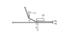
- heating and pressurization are performed by the thermal head 100.
- Each of the transfer medium Ma and the transfer medium Mb is conveyed so as to pass through the transfer position Pt and the peeling position Pe.
- the transfer medium Ma is superposed on the transfer medium Mb and receives heat and pressure from the thermal head 100.
- the transfer medium Ma is peeled off from the transfer medium Mb downstream of the transfer position Pt in the transport path.
- the position where the transfer medium Ma starts to separate from the transfer medium Mb is the peeling position Pe. That is, the direction in which the transfer medium Ma is conveyed from the peeling position Pe and the direction in which the transfer medium Mb is conveyed from the peeling position Pe are different from each other.
- the angle formed by the first direction in which the transfer medium Ma is conveyed from the peeling position Pe and the second direction in which the transfer medium Mb is conveyed from the peeling position Pe is the peeling angle ⁇ . is there.
- the peeling angle ⁇ is an angle formed between the transport path of the transfer medium Ma and the transport path of the transfer medium Mb at the peeling position Pe.
- the transfer path of the transfer medium Ma is defined by the transfer mechanism of the transfer medium Ma
- the transfer path of the transfer medium Mb is defined by the transfer mechanism of the transfer medium Mb.
- the transport mechanism of each medium includes a mechanism such as a roller that feeds and collects the medium, and a mechanism that supports the medium in the middle of the transport path.
- the transfer direction of the transfer medium Ma is defined by the path defining member 110 included in the transfer mechanism of the transfer medium Ma, whereby the peeling position Pe and the peeling angle ⁇ are determined.
- the routing member 110 comes into contact with the transfer medium Ma downstream of the transfer position Pt and changes the direction in which the transfer medium Ma is conveyed.
- the routing member 110 is arranged at a position downstream of the transfer position Pt and in contact with the transfer medium Ma superimposed on the transfer medium Mb. Then, the peeling position Pe is formed immediately after the contact position between the routing member 110 and the transfer medium Ma. That is, the peeling position Pe is determined by the position of the path defining member 110 in the direction along the flow of the medium. The direction in which the transfer medium Mb is conveyed does not change between the upstream and downstream of the peeling position Pe.
- the peeling position Pe When the point through which the transfer medium Ma passes is defined at a predetermined position downstream from the peeling position Pe by the position of a member supporting the transfer medium Ma, a roller for winding the transfer medium Ma, or the like, the peeling position Pe The peeling angle ⁇ changes according to. Therefore, the peeling angle ⁇ is determined by the position of the path defining member 110 in the direction along the flow of the medium.
- the routing member 110 is arranged at a position downstream of the transfer position Pt and downstream of the peeling position Pe and in contact with the transfer medium Ma peeled from the transfer medium Mb. ..
- the peeling position Pe is formed in the vicinity of the transfer position Pt, and the transfer medium Ma is conveyed in the direction from the peeling position Pe toward the contact position with the routing member 110.
- the direction in which the transfer medium Mb is conveyed does not change between the upstream and downstream of the peeling position Pe.
- the peeling angle ⁇ is determined by the position of the path defining member 110 with respect to the peeling position Pe. In other words, the peeling angle ⁇ is determined by the position of the path defining member 110 in the direction along the flow of the medium and the height direction orthogonal to the direction.
- the path defining member 110 may have an inclined surface having a predetermined angle, for example, and the inclined surface may be brought into contact with the transfer medium Ma downstream from the peeling position Pe.
- the transfer medium Ma is conveyed from the peeling position Pe along the inclined surface. That is, the path defining member 110 defines the direction in which the transfer medium Ma is conveyed from the peeling position Pe, and the peeling angle ⁇ is determined by this.
- the routing member 110 has a function of changing the direction in which the transfer medium Ma is conveyed between the upstream and the downstream of the contact position between the routing member 110 and the transfer medium Ma. Then, at least one of the peeling position Pe and the peeling angle ⁇ is determined because the routing member 110 changes the transport direction of the transfer medium Ma.
- the printing apparatus may not be provided with the path defining member 110, and the peeling position Pe and the peeling angle ⁇ may be defined depending on the position of the roller or the like that winds up the transfer medium Ma. Further, the direction in which the transfer medium Mb is conveyed is changed in the middle of the transfer path, which may contribute to the definition of the peeling position Pe and the peeling angle ⁇ .
- Print device configuration The configuration of the printing apparatus of this embodiment will be described.
- the printing apparatus of this embodiment is configured so that the peeling angle ⁇ is 30 ° or less.
- the printing apparatus 20 of the present embodiment includes a head mechanism 30 including a thermal head 31, a platen roller 40 facing the thermal head 31, and a ribbon transport portion 50 which is a transport mechanism of the thermal transfer ribbon 10.
- a medium transport unit 60 which is a transport mechanism for the transfer medium 19, is provided.
- the ribbon transport unit 50 defines a transport path for the thermal transfer ribbon 10, and transports the thermal transfer ribbon 10 along the transfer path.
- the medium transport unit 60 defines a transport path for the transfer medium 19, and transports the transfer medium 19 along the transfer path.
- the transport path of the thermal transfer ribbon 10 is an example of the first transport path
- the transport path of the transfer medium 19 is an example of the second transport path.
- the platen roller 40 supports the transfer medium 19 and rotates with the width direction of the transport path of the transfer medium 19 as the axial direction.
- Each of the transfer path of the thermal transfer ribbon 10 and the transfer path of the transfer medium 19 includes a transfer position Pt and a peeling position Pe.
- the transfer position Pt is a position where the thermal transfer ribbon 10 stacked on the transfer medium 19 receives heat and pressure from the thermal head 31.
- the thermal transfer ribbon 10 is in contact with the transfer medium 19 so that the transfer medium 19 and the transfer layer 12 are in contact, and the thermal transfer ribbon 10 and the transfer medium 19 are between the thermal head 31 and the platen roller 40. It is sandwiched between. Heat and pressure are applied to the thermal transfer ribbon 10 from the side where the substrate 11 is located relative to the transfer layer 12.
- the peeling position Pe is downstream from the transfer position Pt and is a position at which the thermal transfer ribbon 10 from the transfer medium 19 starts to be peeled.
- a part of the transfer layer 12, that is, the transfer layer 12 of the portion to be transferred is peeled from the base material 11 and remains on the transfer medium 19.
- the thermal head 31 includes a plurality of heat generating resistors.
- the plurality of heat generating resistors are configured to be able to selectively generate heat by energization, and are arranged along the width direction of the transport path of the thermal transfer ribbon 10 and the transfer medium 19.
- the thermal transfer ribbon 10 faces the heat generating resistor at the transfer position Pt. At the transfer position Pt, the heat-generating resistor that generates heat presses the thermal transfer ribbon 10 toward the transfer medium 19.
- the portion of the thermal transfer ribbon 10 on which the generated heat-generating resistor is pressed is the transfer target region.
- the transfer layer 12 in the transfer target region is transferred to the transfer medium 19, and dots containing the hologram are formed on the transfer medium 19.
- the diameter of the region pressed by one heat generating resistor, that is, the dot diameter is, for example, 10 ⁇ m or more and 500 ⁇ m or less.
- the thermal head 31 includes a control unit that controls energization of the heat generation resistor, and the control unit heats the heat generation resistor at a position corresponding to the data to be printed.
- the control unit heats the heat generation resistor at a position corresponding to the data to be printed.
- the ribbon transport section 50 and the medium transport section 60 are configured so that the peeling angle ⁇ is 30 ° or less. That is, the ribbon transport section 50 defines the transport path of the thermal transfer ribbon 10 and the medium transport section 60 defines the transport path of the transfer medium 19 so that the peeling angle ⁇ is 30 ° or less.
- the thermal transfer ribbon 10 is rolled into a roll before use.
- the ribbon transport unit 50 includes a delivery roller that feeds the heat transfer ribbon 10 from the roll toward the transfer position Pt, a take-up roller that winds up the used heat transfer ribbon 10 downstream from the peeling position Pe, and a feed roller and a take-up roller. Includes a plurality of support rollers that support the thermal transfer ribbon 10 between them.
- the transfer medium 19 may be a paper or film cut to a predetermined length, or may be a strip-shaped film supplied from a roll.
- the medium transport unit 60 is a feeding mechanism that feeds the transfer medium 19 toward the transfer position Pt, a recovery mechanism that collects the transfer medium 19 downstream from the peeling position Pe, and a transfer mechanism between the delivery mechanism and the recovery mechanism. Includes rollers and supports that support the medium 19.
- the ribbon transport unit 50 further includes a routing member 51.
- the routing member 51 comes into contact with the thermal transfer ribbon 10 from the position side of the base material 11 on the thermal transfer ribbon 10 downstream of the transfer position Pt. Then, when the routing member 51 comes into contact with the thermal transfer ribbon 10, the direction in which the thermal transfer ribbon 10 is conveyed changes between upstream and downstream of the contact position between the routing member 51 and the thermal transfer ribbon 10.
- the path defining member 51 is connected to the head mechanism 30.
- the path defining member 51 has an inclined surface, and the inclined surface comes into contact with the thermal transfer ribbon 10.
- the peeling position Pe is formed near the end portion located upstream in the portion where the path defining member 51 and the thermal transfer ribbon 10 are in contact with each other.
- the thermal transfer ribbon 10 is conveyed from the peeling position Pe along the inclined surface of the path defining member 51.
- the peeling position Pe is defined by the position of the path defining member 51, and the peeling angle ⁇ is defined by the angle of the inclined surface.
- the configuration in which the path defining member 51 defines the peeling position Pe and the peeling angle ⁇ may be different from the configuration shown in FIG. 4, and in the printing apparatus 20, the peeling position Pe and the peeling by the path defining member 110 described above may be different. Any of the specified configurations of the angle ⁇ can be adopted. In short, the path defining member 51 defines the transport direction of the thermal transfer ribbon 10, and this may be one of the factors that define the peeling angle ⁇ .
- the peeling angle ⁇ is 30 ° or less, the formation of the edge portion can be suppressed due to the increase in the adhesion force F.
- the peeling angle ⁇ is more preferably 15 ° or less. Further, in order to facilitate the production of the printing apparatus 20, the peeling angle ⁇ is preferably 2 ° or more.
- the head mechanism 30 includes a movable portion 32 that changes the position of the thermal head 31 with respect to the transport path of the thermal transfer ribbon 10.
- the movable portion 32 changes the distance between the thermal transfer ribbon 10 and the thermal head 31 by moving the movable portion 32.
- the movable portion 32 is connected to the thermal head 31 on the opposite side of the transfer path of the thermal transfer ribbon 10 to the thermal head 31.
- the movable portion 32 brings the thermal head 31 close to the thermal transfer ribbon 10.
- the path defining member 51 is connected to a portion of the head mechanism 30 that is different from the thermal head 31. Specifically, the path defining member 51 is supported by a support portion 33, which is a portion of the head mechanism 30 located on the opposite side of the thermal head 31 with respect to the movable portion 32.
- the support portion 33 is, for example, a portion that functions as a frame that supports the movable portion 32 and the thermal head 31.
- the path defining member 51 Since the path defining member 51 is in contact with the heat transfer ribbon 10 near the peeling position Pe, when the path defining member 51 is at a high temperature, the heat is transferred to the heat transfer ribbon 10 and the temperature of the heat transfer ribbon 10 at the peeling position Pe rises. To do. However, since the adhesion F of the thermal transfer ribbon 10 increases as the temperature of the thermal transfer ribbon 10 decreases, it is preferable that the temperature of the thermal transfer ribbon 10 at the peeling position Pe is low.
- the routing member 51 is connected to a portion of the head mechanism 30 that is different from the thermal head 31, the routing member 51 is connected to the thermal head 31 that becomes hot due to heat generation. Compared with the case, the path defining member 51 is less likely to become hot. Therefore, since the amount of heat transferred from the path defining member 51 to the heat transfer ribbon 10 can be suppressed, the temperature of the heat transfer ribbon 10 at the peeling position Pe can be suppressed low.
- the support portion 33 that functions as a frame has a large surface area, it has high heat dissipation and is unlikely to reach a high temperature. Therefore, since the routing member 51 is connected to the support portion 33, the temperature of the routing member 51 can be suppressed to be lower, and as a result, the temperature of the thermal transfer ribbon 10 at the peeling position Pe can be suppressed to be lower. ..
- the printing device 20 may not be provided with the path defining member 51, and the peeling angle ⁇ may be defined depending on the position of the roller or the like that winds up the thermal transfer ribbon 10. Further, the direction in which the transfer medium 19 is conveyed may be changed in the middle of the transfer path, which may be one of the factors that define the peeling angle ⁇ . Further, the temperature of the routing member 51 may be lowered by providing the cooling mechanism of the routing member 51, whereby the temperature of the thermal transfer ribbon 10 at the peeling position Pe may be kept low.
- a first sample S1 corresponding to the transfer target region R1 and a second sample S2 corresponding to the peripheral region R2 were prepared.
- the first sample S1 is a sample in which heat and pressure are applied to the thermal transfer ribbon 10.
- the second sample S2 is a sample in which only heat is applied to the thermal transfer ribbon 10.
- the first sample S1 was prepared using a transfer machine equipped with a thermal head equipped with a heat generating resistor array. The resistance of the heating resistor array is 3000 ⁇ . A voltage of 24 V and a total of 3 ms of electrical energy were applied to the heat-generating resistor array to press the sample, and the first sample S1 was prepared. The pressing force was 2.5 kgf.
- the second sample S2 was subjected to heat of 80 ° C. for 5 seconds.
- the thickness and material of the thermal transfer ribbon 10 in each of the samples S1 and S2 are as follows. Each sample S1 and S2 was formed in a strip shape having a width of 20 mm. ⁇ Thickness and material> Base material thickness: 12 ⁇ m Material: Polyethylene terephthalate release layer Thickness: 0.8 ⁇ m Material: Acrylic release agent (MCS5041: manufactured by Dainippon Ink and Chemicals Co., Ltd.) Optical functional layer Thickness: 0.8 ⁇ m Material: [Main agent] Acrylic polyol resin (MCA4039: manufactured by DIC Corporation) [Curing agent] Isocyanate curing agent (MCX102: manufactured by DIC Corporation) Adhesive layer thickness: 0.6 ⁇ m Material: Epoxy resin (EP1001: manufactured by Mitsubishi Chemical Corporation), polyester resin (Vy300: manufactured by Toyobo Co., Ltd.)
- the test method of the adhesion force F measurement test will be described.
- the sample is fixed to the stage of the testing machine so that the adhesive layer 15 is in contact with the stage surface, and a load is applied to the base material 11 with the angle of the stage surface with respect to the vertical direction as the target peeling angle ⁇ .
- the base material 11 was pulled vertically downward.
- the load applied to the base material 11 was gradually increased, and the load when the base material 11 was peeled off from the release layer 13 was defined as the adhesion force F.
- the adhesion force F was measured by changing the temperature of the sample.
- the sample was heated by heating the stage.
- FIG. 6 shows the measurement results of the adhesion force F for each of the first sample S1 and the second sample S2 when the peeling angle ⁇ is 15 ° and when the peeling angle ⁇ is 90 °. This measurement was performed without heating the sample. That is, the temperature of the sample is room temperature. Room temperature was 23 ° C.
- the adhesion force F when the peeling angle ⁇ is 15 ° is the adhesion force F when the peeling angle ⁇ is 90 °. Remarkably large compared to. Further, when the peeling angle ⁇ is 90 °, there is almost no difference in the adhesion force F between the first sample S1 and the second sample S2, whereas when the peeling angle ⁇ is 15 °, there is no difference. The adhesion F of the two samples S2 was clearly larger than the adhesion F of the first sample S1.
- the transfer layer 12 When the thermal transfer ribbon 10 is peeled off from the transfer medium 19, in the transfer target region R1, the transfer layer 12 is in strong contact with the transfer medium 19, so that the adhesion F is large, that is, the transfer layer 12 and the base. Even when the adhesion with the material 11 is high, the transfer layer 12 is peeled off from the base material 11 and remains on the transfer medium 19. On the other hand, in the peripheral region R2, the adhesion between the transfer layer 12 and the transfer medium 19 is low. Therefore, if the adhesion F is large, the transfer layer is peeled off from the transfer medium 19 when the thermal transfer ribbon 10 is peeled off. 12 is peeled from the transfer medium 19 together with the base material 11. Therefore, the larger the adhesion force F, the more difficult it is for the edge portion to be formed.
- the adhesion F of the peripheral region R2 is larger than that of the transfer target region R1
- the adhesion between the transfer layer 12 and the transfer medium 19 is assumed to be about the same between the transfer target region R1 and the peripheral region R2. Even so, the transfer layer 12 is less likely to be peeled off from the base material 11 in the peripheral region R2 than in the transfer target region R1.
- the adhesion between the transfer layer 12 and the transfer medium 19 in the peripheral region R2 is smaller than the adhesion of the transfer target region R1, so that the peripheral region R2 is even more adherent. As a result, the transfer layer 12 is less likely to be peeled off from the base material 11.
- the peeling angle ⁇ is set to a large angle of about 90 ° in order to reduce the energy required for peeling the thermal transfer ribbon from the transfer medium.
- the printing apparatus 20 of the present embodiment by intentionally reducing the peeling angle ⁇ , it is possible to obtain an effect of suppressing the formation of the edge portion, which cannot be imagined by the conventional printing apparatus.
- FIG. 7 shows the measurement results of the adhesion force F of the first sample S1 and the second sample S2 for each of the case where the sample is not heated and the case where the sample is heated.
- the peeling angle ⁇ is 15 ° C.
- the room temperature is 23 ° C.
- the heating temperature of the sample is 80 ° C.
- the lower the sample temperature the larger the adhesion force F for both the first sample S1 and the second sample S2.
- the lower the sample temperature the larger the difference in the adhesion force F between the first sample S1 and the second sample S2. Therefore, the lower the temperature of the thermal transfer ribbon 10 at the time of peeling, the more the formation of the edge portion can be suppressed.
- the peeling angle ⁇ is 30 ° or less, the effect of suppressing the formation of the edge portion can be obtained as compared with the case where the peeling angle ⁇ is 90 °, regardless of the temperature of the thermal transfer ribbon 10. If the peeling angle ⁇ is 30 ° or less and the temperature of the thermal transfer ribbon 10 at the peeling position Pe is low, the effect of suppressing the formation of the edge portion is further enhanced.
- the diameter of the transfer body which is a portion made of the transfer layer 12 formed on the transfer medium 19 including the edge portion, becomes large.
- the rate of change in the diameter of the transfer member with respect to the applied energy was analyzed for each of the cases where the peeling angle ⁇ was 15 ° and 90 °, the case where the peeling angle ⁇ was 90 ° was found to be the diameter of the transfer body. It was confirmed that the rate of change was large, that is, when the applied energy was increased by a predetermined amount, the amount of increase in the diameter of the transcript became larger.
- the peeling angle ⁇ is 90 ° when the environment in which the transfer is performed changes like the temperature around the thermal head 31 and the degree of heat transfer to the periphery of the transfer target region R1 changes.
- the peeling angle ⁇ is 15 °, it means that the change in the diameter of the transfer body is smaller. Therefore, the smaller the peeling angle ⁇ , the more stable the transfer result can be obtained regardless of the environment in which the transfer is performed. That is, when the peeling angle ⁇ is 30 ° or less, it is possible to obtain the effect of reducing the burden required for preparing the environment in which the transfer is performed when the printing apparatus 20 is used.
- the printing device 20 is used for manufacturing a personal information medium.
- the personal information medium 70 has a card shape.
- the personal information medium 70 is embodied in, for example, an ID card or the like that proves the identity of the owner.
- the personal information medium 70 includes a support 71, a hologram portion 72, and a coloring portion 73.
- the support 71 supports each of the hologram portion 72 and the coloring portion 73.
- the support 71 may be composed of a plurality of layers.
- the support 71 includes, for example, a resin base material.
- the hologram portion 72 is formed by transferring the transfer layer 12 from the thermal transfer ribbon 10 by the printing apparatus 20. That is, the hologram unit 72 includes a hologram formed by the diffraction structure of the optical functional layer 14.
- the colored portion 73 exhibits a color due to the dye. That is, the color visually recognized in the coloring portion 73 is due to the absorption of light by the dye.
- the coloring portion 73 is formed by printing with toner or ink.
- the hologram unit 72 includes a portion indicating the first personal information Ia, and the coloring portion 73 includes a portion indicating the second personal information Ib.
- the first personal information Ia and the second personal information Ib are personal information about the same person, and specifically, personal information of a person who is the owner of the personal information medium 70.
- Personal information is information that can be used to identify an individual, such as a name, date of birth, address, and facial image.
- each of the first personal information Ia and the second personal information Ib includes a color face image.
- the diffraction structure layer included in the optical functional layer 14 has a red region, a green region, and a blue region along the extending direction of the thermal transfer ribbon 10. It has a structure in which it is repeatedly arranged in a predetermined order.
- the red region is configured to emit red diffracted light in a predetermined direction
- the green region is configured to emit green diffracted light in a predetermined direction
- the blue region is configured to emit green diffracted light in a predetermined direction. It is configured to emit blue diffracted light in the direction.
- the transfer of the transfer layer 12 including the red region, the transfer of the transfer layer 12 including the green region, and the transfer of the transfer layer 12 including the blue region are sequentially performed on the predetermined region of the transfer medium 19, thereby being transferred.
- a color image composed of a set of dots is formed on the medium 19.
- the printing device 20 may be used for manufacturing a printed matter different from the personal information medium 70. Further, the printing apparatus 20 may use a base material contained in the final product such as the personal information medium 70 as the transfer medium 19, and transfer the transfer layer 12 directly to the base material. Alternatively, the printing apparatus 20 may use a base material different from the base material contained in the final product as the transfer medium 19, and transfer the transfer layer 12 from the thermal transfer ribbon 10 to the transfer medium 19. In this case, the transfer layer 12 transferred to the transfer medium 19 is further transferred to the base material contained in the final product to form the product.
- the adhesion force F of the thermal transfer ribbon 10 is larger than that when the peeling angle ⁇ is large. Further, in the thermal transfer ribbon 10, the adhesion force F is larger in the region that receives only heat than in the region that receives heat and pressure. Therefore, even when heat is transferred from the transfer target region R1 to the peripheral region R2, it is possible to prevent the transfer layer 12 from peeling from the base material 11 in the peripheral region R2. Therefore, the formation of the edge portion is suppressed.
- the routing member 51 Since the routing member 51 is connected to a portion different from the thermal head 31, the routing member 51 becomes hotter than when the routing member 51 is connected to the thermal head 31. Is suppressed. As a result, heat is suppressed from being transferred from the path defining member 51 to the heat transfer ribbon 10, so that the heat transfer ribbon 10 is prevented from becoming hot at the peeling position Pe. Therefore, since it is possible to suppress a decrease in the adhesion force F of the thermal transfer ribbon 10, the formation of the edge portion is more preferably suppressed.
- the path defining member 51 is connected to a portion of the head mechanism 30 that is located on the side opposite to the thermal head 31 with respect to the movable portion 32 that moves the thermal head 31, the head mechanism 30 Since the routing member 51 is connected to a portion further away from the thermal head 31, it is possible to accurately suppress the temperature of the routing member 51 from becoming high. Therefore, since the temperature of the thermal transfer ribbon 10 at the peeling position Pe can be suppressed low, the formation of the edge portion can be suppressed more preferably.
Landscapes
- Electronic Switches (AREA)
- Impression-Transfer Materials And Handling Thereof (AREA)
Priority Applications (5)
| Application Number | Priority Date | Filing Date | Title |
|---|---|---|---|
| JP2021555701A JP7435619B2 (ja) | 2019-11-13 | 2019-11-13 | 印刷装置 |
| CN201980101870.9A CN114630753B (zh) | 2019-11-13 | 2019-11-13 | 印刷装置 |
| PCT/JP2019/044573 WO2021095171A1 (ja) | 2019-11-13 | 2019-11-13 | 印刷装置 |
| EP19952150.1A EP4059726B1 (en) | 2019-11-13 | 2019-11-13 | Printing device |
| US17/739,685 US12162291B2 (en) | 2019-11-13 | 2022-05-09 | Printing apparatus |
Applications Claiming Priority (1)
| Application Number | Priority Date | Filing Date | Title |
|---|---|---|---|
| PCT/JP2019/044573 WO2021095171A1 (ja) | 2019-11-13 | 2019-11-13 | 印刷装置 |
Related Child Applications (1)
| Application Number | Title | Priority Date | Filing Date |
|---|---|---|---|
| US17/739,685 Continuation US12162291B2 (en) | 2019-11-13 | 2022-05-09 | Printing apparatus |
Publications (1)
| Publication Number | Publication Date |
|---|---|
| WO2021095171A1 true WO2021095171A1 (ja) | 2021-05-20 |
Family
ID=75912089
Family Applications (1)
| Application Number | Title | Priority Date | Filing Date |
|---|---|---|---|
| PCT/JP2019/044573 Ceased WO2021095171A1 (ja) | 2019-11-13 | 2019-11-13 | 印刷装置 |
Country Status (5)
| Country | Link |
|---|---|
| US (1) | US12162291B2 (https=) |
| EP (1) | EP4059726B1 (https=) |
| JP (1) | JP7435619B2 (https=) |
| CN (1) | CN114630753B (https=) |
| WO (1) | WO2021095171A1 (https=) |
Citations (8)
| Publication number | Priority date | Publication date | Assignee | Title |
|---|---|---|---|---|
| JPH08222837A (ja) * | 1995-02-15 | 1996-08-30 | Ricoh Elemex Corp | 熱転写リボン、それを用いる熱転写記録装置、およびその熱転写リボンを使用する回路基板の製作方法 |
| JP2002079701A (ja) * | 2000-09-04 | 2002-03-19 | Alps Electric Co Ltd | 熱転写プリンタ |
| JP2010125803A (ja) * | 2008-11-28 | 2010-06-10 | Nissha Printing Co Ltd | ホログラム調加飾シートの製造方法とこれに用いるホログラム調パターン形成用リボン、および成形同時加飾成形品の製造方法 |
| JP2012066488A (ja) * | 2010-09-24 | 2012-04-05 | Dainippon Printing Co Ltd | 熱転写リボン及びこれを用いた画像形成方法、並びに熱転写リボンの製造方法 |
| JP2013022797A (ja) * | 2011-07-20 | 2013-02-04 | Sinfonia Technology Co Ltd | 熱転写プリンタ |
| JP2013121676A (ja) * | 2011-12-09 | 2013-06-20 | Sinfonia Technology Co Ltd | 熱転写プリンタ |
| US20130215209A1 (en) * | 2012-02-17 | 2013-08-22 | Markem-Imaje Limited | Printing apparatus and method of operation of a printing apparatus |
| JP2015052719A (ja) * | 2013-09-06 | 2015-03-19 | 大日本印刷株式会社 | ホログラム積層体の製造方法 |
Family Cites Families (9)
| Publication number | Priority date | Publication date | Assignee | Title |
|---|---|---|---|---|
| US5072238A (en) * | 1988-03-30 | 1991-12-10 | Canon Kabushiki Kaisha | Heat transfer recording method |
| JPH0426750U (https=) * | 1990-06-26 | 1992-03-03 | ||
| JP3370868B2 (ja) * | 1996-11-11 | 2003-01-27 | シャープ株式会社 | 熱転写プリント装置 |
| JP3737037B2 (ja) * | 2001-05-31 | 2006-01-18 | ニスカ株式会社 | 印刷装置 |
| US6857736B2 (en) * | 2001-08-10 | 2005-02-22 | Seiko Epson Corporation | Ink jet recorded matter and production process therefor, and thermal transfer sheet, ink jet recording apparatus, thermal transfer apparatus, and ink jet recording medium |
| US20120276922A1 (en) | 2011-04-28 | 2012-11-01 | Ho-Sung Chien | Method of Handling Velocity Triggered SUPL Service and Related Communication Device |
| DE102012110222B4 (de) * | 2012-10-25 | 2015-05-07 | Leonhard Kurz Stiftung & Co. Kg | Heißprägevorrichtung |
| JP6351068B2 (ja) * | 2014-05-30 | 2018-07-04 | サトーホールディングス株式会社 | 熱転写プリンタ |
| WO2016084851A1 (ja) * | 2014-11-28 | 2016-06-02 | 凸版印刷株式会社 | 画像形成体製造装置、転写リボン及び画像形成体製造方法 |
-
2019
- 2019-11-13 CN CN201980101870.9A patent/CN114630753B/zh active Active
- 2019-11-13 EP EP19952150.1A patent/EP4059726B1/en active Active
- 2019-11-13 JP JP2021555701A patent/JP7435619B2/ja active Active
- 2019-11-13 WO PCT/JP2019/044573 patent/WO2021095171A1/ja not_active Ceased
-
2022
- 2022-05-09 US US17/739,685 patent/US12162291B2/en active Active
Patent Citations (8)
| Publication number | Priority date | Publication date | Assignee | Title |
|---|---|---|---|---|
| JPH08222837A (ja) * | 1995-02-15 | 1996-08-30 | Ricoh Elemex Corp | 熱転写リボン、それを用いる熱転写記録装置、およびその熱転写リボンを使用する回路基板の製作方法 |
| JP2002079701A (ja) * | 2000-09-04 | 2002-03-19 | Alps Electric Co Ltd | 熱転写プリンタ |
| JP2010125803A (ja) * | 2008-11-28 | 2010-06-10 | Nissha Printing Co Ltd | ホログラム調加飾シートの製造方法とこれに用いるホログラム調パターン形成用リボン、および成形同時加飾成形品の製造方法 |
| JP2012066488A (ja) * | 2010-09-24 | 2012-04-05 | Dainippon Printing Co Ltd | 熱転写リボン及びこれを用いた画像形成方法、並びに熱転写リボンの製造方法 |
| JP2013022797A (ja) * | 2011-07-20 | 2013-02-04 | Sinfonia Technology Co Ltd | 熱転写プリンタ |
| JP2013121676A (ja) * | 2011-12-09 | 2013-06-20 | Sinfonia Technology Co Ltd | 熱転写プリンタ |
| US20130215209A1 (en) * | 2012-02-17 | 2013-08-22 | Markem-Imaje Limited | Printing apparatus and method of operation of a printing apparatus |
| JP2015052719A (ja) * | 2013-09-06 | 2015-03-19 | 大日本印刷株式会社 | ホログラム積層体の製造方法 |
Also Published As
| Publication number | Publication date |
|---|---|
| JP7435619B2 (ja) | 2024-02-21 |
| EP4059726A1 (en) | 2022-09-21 |
| EP4059726A4 (en) | 2023-07-19 |
| CN114630753B (zh) | 2023-11-03 |
| US20220258491A1 (en) | 2022-08-18 |
| EP4059726B1 (en) | 2024-08-07 |
| US12162291B2 (en) | 2024-12-10 |
| CN114630753A (zh) | 2022-06-14 |
| JPWO2021095171A1 (https=) | 2021-05-20 |
Similar Documents
| Publication | Publication Date | Title |
|---|---|---|
| US20120003346A1 (en) | Sheet surface treating apparatus | |
| US10160247B2 (en) | Plastic card printing with thermally transferrable adhesive | |
| US20250115057A1 (en) | Thermal transfer printer, method for producing printed product, printed product, combination of thermal transfer sheet and intermediate transfer medium, intermediate transfer medium, and thermal transfer sheet | |
| US10105981B2 (en) | Transfer lamination | |
| JP2020199682A (ja) | プリンタおよび間接転写記録方法 | |
| JP7435619B2 (ja) | 印刷装置 | |
| JP6834279B2 (ja) | 熱転写システム | |
| WO2002070263A9 (en) | Printer with reverse image sheet | |
| JP2005319777A (ja) | 受容層転写材及び転写シート、並びにそれを用いた画像形成方法 | |
| JP2010228289A (ja) | 印画物製造方法、印画物製造装置、および製本物 | |
| JP2004299377A (ja) | 転写用加圧ロール、転写装置及びインクジェット記録装置 | |
| JP4966491B2 (ja) | 熱転写方法及び熱転写装置及びインクジェット記録装置 | |
| US8585034B1 (en) | Receiver supply using cut sheet media | |
| EP3505354B1 (en) | Thermal printhead having asymmetric recording elements | |
| JP2003341243A (ja) | 画像記録方法およびそれに使用する画像記録装置 | |
| CN114286753B (zh) | 热转印印刷装置、印刷物的制造方法以及中间转印介质 | |
| JP4019797B2 (ja) | プリンタ装置及びプリント方法 | |
| JP7275974B2 (ja) | 熱転写システム | |
| JP2012013870A (ja) | 光沢処理装置 | |
| JP2012013868A (ja) | 加熱装置 | |
| JP2006263978A (ja) | 熱転写記録方法および熱転写記録装置 | |
| JP2004338220A (ja) | インクリボン、およびこのインクリボンを用いた記録方法 | |
| JP2020116821A (ja) | 熱転写システム | |
| JP6331142B2 (ja) | Icカードを製造する方法 | |
| US8820915B2 (en) | Method for handling cut sheet media |
Legal Events
| Date | Code | Title | Description |
|---|---|---|---|
| 121 | Ep: the epo has been informed by wipo that ep was designated in this application |
Ref document number: 19952150 Country of ref document: EP Kind code of ref document: A1 |
|
| ENP | Entry into the national phase |
Ref document number: 2021555701 Country of ref document: JP Kind code of ref document: A |
|
| NENP | Non-entry into the national phase |
Ref country code: DE |
|
| ENP | Entry into the national phase |
Ref document number: 2019952150 Country of ref document: EP Effective date: 20220613 |