WO2021084936A1 - クラッチ機構および動力工具 - Google Patents
クラッチ機構および動力工具 Download PDFInfo
- Publication number
- WO2021084936A1 WO2021084936A1 PCT/JP2020/034445 JP2020034445W WO2021084936A1 WO 2021084936 A1 WO2021084936 A1 WO 2021084936A1 JP 2020034445 W JP2020034445 W JP 2020034445W WO 2021084936 A1 WO2021084936 A1 WO 2021084936A1
- Authority
- WO
- WIPO (PCT)
- Prior art keywords
- engaging member
- diameter
- holding hole
- rotation axis
- clutch plate
- Prior art date
- Legal status (The legal status is an assumption and is not a legal conclusion. Google has not performed a legal analysis and makes no representation as to the accuracy of the status listed.)
- Ceased
Links
Images


Classifications
-
- B—PERFORMING OPERATIONS; TRANSPORTING
- B25—HAND TOOLS; PORTABLE POWER-DRIVEN TOOLS; MANIPULATORS
- B25F—COMBINATION OR MULTI-PURPOSE TOOLS NOT OTHERWISE PROVIDED FOR; DETAILS OR COMPONENTS OF PORTABLE POWER-DRIVEN TOOLS NOT PARTICULARLY RELATED TO THE OPERATIONS PERFORMED AND NOT OTHERWISE PROVIDED FOR
- B25F5/00—Details or components of portable power-driven tools not particularly related to the operations performed and not otherwise provided for
- B25F5/001—Gearings, speed selectors, clutches or the like specially adapted for rotary tools
-
- B—PERFORMING OPERATIONS; TRANSPORTING
- B25—HAND TOOLS; PORTABLE POWER-DRIVEN TOOLS; MANIPULATORS
- B25B—TOOLS OR BENCH DEVICES NOT OTHERWISE PROVIDED FOR, FOR FASTENING, CONNECTING, DISENGAGING OR HOLDING
- B25B23/00—Details of, or accessories for, spanners, wrenches, screwdrivers
- B25B23/14—Arrangement of torque limiters or torque indicators in wrenches or screwdrivers
-
- F—MECHANICAL ENGINEERING; LIGHTING; HEATING; WEAPONS; BLASTING
- F16—ENGINEERING ELEMENTS AND UNITS; GENERAL MEASURES FOR PRODUCING AND MAINTAINING EFFECTIVE FUNCTIONING OF MACHINES OR INSTALLATIONS; THERMAL INSULATION IN GENERAL
- F16D—COUPLINGS FOR TRANSMITTING ROTATION; CLUTCHES; BRAKES
- F16D43/00—Automatic clutches
- F16D43/02—Automatic clutches actuated entirely mechanically
- F16D43/20—Automatic clutches actuated entirely mechanically controlled by torque, e.g. overload-release clutches, slip-clutches with means by which torque varies the clutching pressure
- F16D43/202—Automatic clutches actuated entirely mechanically controlled by torque, e.g. overload-release clutches, slip-clutches with means by which torque varies the clutching pressure of the ratchet type
- F16D43/204—Automatic clutches actuated entirely mechanically controlled by torque, e.g. overload-release clutches, slip-clutches with means by which torque varies the clutching pressure of the ratchet type with intermediate balls or rollers
- F16D43/206—Automatic clutches actuated entirely mechanically controlled by torque, e.g. overload-release clutches, slip-clutches with means by which torque varies the clutching pressure of the ratchet type with intermediate balls or rollers moving axially between engagement and disengagement
-
- F—MECHANICAL ENGINEERING; LIGHTING; HEATING; WEAPONS; BLASTING
- F16—ENGINEERING ELEMENTS AND UNITS; GENERAL MEASURES FOR PRODUCING AND MAINTAINING EFFECTIVE FUNCTIONING OF MACHINES OR INSTALLATIONS; THERMAL INSULATION IN GENERAL
- F16D—COUPLINGS FOR TRANSMITTING ROTATION; CLUTCHES; BRAKES
- F16D7/00—Slip couplings, e.g. slipping on overload, for absorbing shock
- F16D7/04—Slip couplings, e.g. slipping on overload, for absorbing shock of the ratchet type
- F16D7/06—Slip couplings, e.g. slipping on overload, for absorbing shock of the ratchet type with intermediate balls or rollers
- F16D7/08—Slip couplings, e.g. slipping on overload, for absorbing shock of the ratchet type with intermediate balls or rollers moving axially between engagement and disengagement
Definitions
- the present invention relates to a clutch mechanism for limiting the rotational torque transmitted from the input shaft to the output shaft, and a power tool provided with the clutch mechanism.
- a clutch mechanism is provided between the rotary drive shaft of the drive unit and the output shaft to which a machining tool such as a driver bit or a drill bit is attached.
- a machining tool such as a driver bit or a drill bit is attached.
- Patent Documents 1 and 2 For example, by providing the electric driver with a clutch mechanism, it is possible to limit the rotational torque applied to the screw via the driver bit and prevent the screw from being damaged.
- the clutch mechanism releases the drive connection due to the screw seating and the rotational torque suddenly increases, it is judged that the screw tightening is completed and the motor drive is stopped or the number of screw tightening is counted. You can also do it.
- the clutch ball arranged on the output shaft side is arranged so as to engage with the protrusion of the clutch member on the rotation drive shaft side in the rotational direction, and the clutch ball is clutched by a spring.
- the clutch ball is urged to the side of the member to maintain the state of being engaged with the protrusion. While the clutch ball is engaged with the protrusion in the rotational direction, the rotational torque is transmitted from the rotational drive shaft to the output shaft, and when an excessive rotational torque acts, the clutch ball resists the urging force of the spring and of the rotational axis. By shifting in the direction, the engagement between the clutch ball and the protrusion in the rotational direction is released, and the transmission of the rotational torque is released.
- the maximum rotational torque that can be transmitted by the clutch mechanism depends on the urging force of the spring, the displacement amount of the clutch ball when the clutch mechanism is released, the radial position where the clutch ball engages with the protrusion of the clutch member, and the like. .. Therefore, for example, the maximum rotational torque that can be transmitted by the clutch mechanism can be changed by changing the size and arrangement of the clutch balls.
- the size of the holding hole for holding the clutch ball is usually set according to the size of the clutch ball, it cannot be replaced with a clutch ball having a different size. Further, since the position of the clutch ball is determined by the position of the holding hole, the position of the clutch ball cannot be shifted.
- a plurality of types of members having holding holes for holding the clutch balls formed at different sizes and different positions are prepared in accordance with the required maximum rotational torque. It is necessary to select and use the member. Then, the types of parts that must be prepared increase and the cost increases. Further, when the maximum rotational torque is to be changed later, not only the clutch ball but also the member holding the clutch ball must be replaced, which complicates the work.
- the present invention provides a clutch mechanism capable of changing the maximum rotational torque that can be transmitted without changing the parts that hold the engaging member (clutch ball), and a power tool provided with such a clutch mechanism. With the goal.
- a clutch mechanism arranged between an input shaft and an output shaft to limit the rotational torque transmitted from the input shaft to the output shaft.
- a first clutch plate that is driven and connected to one of an input shaft and an output shaft, is rotatably arranged around a rotation axis, and has an engaging protrusion that protrudes in the direction of the rotation axis.
- a second clutch plate that is drive-connected to the other of the input shaft and the output shaft, faces the first clutch plate in the direction of the rotation axis, and is rotatably arranged around the rotation axis.
- a second clutch plate having an inner holding hole penetrating in the direction of the rotation axis and an outer holding hole penetrating in the direction of the rotation axis at a position radially outside the inner holding hole.
- An engaging member that is selectively arranged in one of the inner holding holes and the outer holding holes and is displaceably held in the one holding hole in the direction of the rotation axis.
- a slide member that abuts on the engaging member in the direction of the rotation axis and presses the engaging member toward the first clutch plate.
- the clutch mechanism is designed so that the maximum rotational torque is larger when the engaging member is selectively arranged in the outer holding hole than when the engaging member is selectively arranged in the inner holding hole.
- the second clutch plate is formed with an inner holding hole and an outer holding hole located radially outside the inner holding hole, and the engaging member is included in the inner holding hole and the outer holding hole. It is designed to be selectively placed on one side. It is possible to change the maximum rotational torque that can be transmitted by the clutch mechanism without replacing the second clutch plate by simply selecting whether to place the engaging member in the inner holding hole or the outer holding hole at the time of assembly. It becomes.
- the outer holding hole has a larger diameter than the inner holding hole
- the engaging member has a smaller diameter spherical engaging member corresponding to the inner holding hole and a larger diameter than the small diameter engaging member.
- the spherical engaging member having a diameter and having a large diameter corresponding to the outer holding hole may be selected so as to correspond to the one holding hole.
- the first clutch plate has an inner engaging surface that engages with the small diameter spherical engaging member when the small diameter spherical engaging member is arranged in the inner holding hole, and the inside of the outer holding hole.
- the large-diameter spherical engaging member has an outer engaging surface that engages with the large-diameter spherical engaging member when the large-diameter spherical engaging member is arranged, and the inner engaging surface has the small-diameter spherical engaging member. It can be made to protrude toward the second clutch plate from the outer engaging surface by the difference in diameter between the large diameter spherical engaging member and the large diameter spherical engaging member.
- a clutch mechanism arranged between an input shaft and an output shaft to limit the rotational torque transmitted from the input shaft to the output shaft.
- a first clutch plate that is driven and connected to one of an input shaft and an output shaft, is rotatably arranged around a rotation axis, and has an engaging protrusion that protrudes in the direction of the rotation axis.
- a second clutch plate that is drive-connected to the other of the input shaft and the output shaft, faces the first clutch plate in the direction of the rotation axis, and is rotatably arranged around the rotation axis.
- a second clutch plate having a small-diameter holding hole penetrating in the direction of the rotation axis and a large-diameter holding hole having a diameter larger than that of the small-diameter holding hole and penetrating in the direction of the rotation axis.
- An engaging member selected from a small-diameter engaging member corresponding to the small-diameter holding hole and a large-diameter engaging member having a larger diameter than the small-diameter engaging member and corresponding to the large-diameter holding hole.
- An engaging member that is arranged in the corresponding holding hole of the small-diameter holding hole and the large-diameter holding hole and is displaceably held in the corresponding holding hole in the direction of the rotation axis.
- a slide member that abuts on the engaging member in the direction of the rotation axis and presses the engaging member toward the first clutch plate.
- the engaging member is displaced together with the slide member in the direction of the rotation axis by the engaging protrusion, and the engagement between the engaging protrusion and the engaging member in the rotation direction is released. As a result, the transmission of the rotational torque is released.
- the maximum rotational torque is higher when the large-diameter engaging member is selectively arranged in the large-diameter holding hole than when the small-diameter engaging member is selectively arranged in the small-diameter holding hole.
- a small-diameter holding hole and a large-diameter holding hole having a larger diameter than the small-diameter holding hole are formed in the second clutch plate, and among the small-diameter engaging member and the large-diameter engaging member.
- One is selectively arranged in the corresponding holding hole.
- the present invention A drive unit with an input shaft and An output shaft with a tool mounting part to which a machining tool is mounted,
- the clutch mechanism described above which is arranged between the input shaft and the output shaft, Provide a power tool equipped with.
- FIG. 1 It is a functional block diagram of the electric driver of FIG. It is an enlarged view of the clutch mechanism of the electric driver of FIG. 1 and its surroundings. It is an enlarged view of the clutch mechanism and its surroundings which shows the state which the tubular shaft part of an output shaft is pushed. It is an exploded perspective view seen from above of the component which constitutes a clutch mechanism. It is an exploded perspective view seen from the bottom of the component constituting a clutch mechanism. It is an enlarged view of the clutch mechanism and its surroundings which shows the state which the clutch mechanism has released the transmission of the rotational torque. It is a flowchart which shows the operation at the time of determining the wear state.
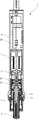
- the electric driver (power tool) 1 includes a tool housing 10, an electric motor (drive unit) 12 arranged in the tool housing 10, and a driver bit (machining).
- An output shaft 16 having a tool mounting portion 14 to which a tool) can be detachably attached, a planetary gear mechanism 20 that decelerates and transmits the rotation of a rotation drive shaft (input shaft) 18 of an electric motor 12, and a planetary gear mechanism 20.
- a clutch mechanism 22 arranged between the output shaft 16 and the clutch mechanism 22 is provided. The rotational torque of the electric motor 12 is transmitted to the output shaft 16 via the planetary gear mechanism 20 and the clutch mechanism 22.
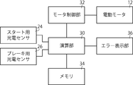
- a start photoelectric sensor 24 for starting the drive of the electric motor 12 and a brake photoelectric sensor 26 for stopping the drive of the electric motor 12 are provided in the tool housing 10, and will be described later.
- the drive and stop of the electric motor 12 are controlled based on the output values of the photoelectric sensors 24 and 26.
- the control circuit 28 arranged in the tool housing 10 stores a calculation unit 30, a motor control unit 32 for performing drive control of the electric motor 12, a control program, control parameters, and the like.
- a memory 34 is provided for this purpose.
- the start photoelectric sensor 24 and the brake photoelectric sensor 26 are connected to the calculation unit 30, and the calculation unit 30 starts and stops driving the electric motor 12 based on the output values of the start photoelectric sensor 24 and the brake photoelectric sensor 26.
- the electric screwdriver 1 also includes an error display unit 36 arranged at a position that is easy for the operator to see.
- the error display unit 36 has an LED, and when an error occurs, the LED emits light to display the state to the operator.
- the start photoelectric sensor 24 has a light projecting unit (not shown) and a light receiving unit 24a facing each other, and receives light emitted from the light emitting unit by the light receiving unit 24a, and the amount of light received by the light receiving unit 24a.
- the output value is output according to.
- the photoelectric sensor 26 for a brake also has a light emitting unit (not shown) and a light receiving unit 26a facing each other, and the light emitted from the light emitting unit is received by the light receiving unit 26a, and the amount of light received by the light receiving unit 26a.
- the output value is output according to.
- the start photoelectric sensor 24 and the brake photoelectric sensor 26 are configured so that the output value increases as the amount of light received by the light receiving units 24a and 26a decreases.
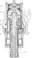
- the output shaft 16 has a solid shaft portion 38 connected to the clutch mechanism 22 and a tubular shaft portion 40 arranged so as to slide on the outer peripheral surface 38a of the solid shaft portion 38. It consists of.
- the solid shaft portion 38 and the tubular shaft portion 40 are fixed in the rotational direction.
- a spherical locker 44 is arranged in the locker holding hole 42 formed in the tubular shaft portion 40, and a sleeve 46 is arranged on the outer peripheral surface 40a of the tubular shaft portion 40. When the sleeve 46 is displaced from the position shown in the drawing to the tip side (lower side when viewed in the drawing), the locker 44 can be displaced outward in the radial direction.
- the driver bit is fixed to the output shaft 16.
- the tool mounting portion 14 of the output shaft 16 is composed of the tubular shaft portion 40, the locker 44, and the sleeve 46.
- the tubular shaft portion 40 of the output shaft 16 becomes the tool housing as shown in FIG. It is pushed into 10.
- the switch plate 52 arranged at the rear end portion 50 of the tubular shaft portion 40 also displaces the tubular shaft portion 40 together.
- the switch plate 52 enters between the light emitting unit and the light receiving unit 24a of the start photoelectric sensor 24, and partially blocks the light projected from the light emitting unit toward the light receiving unit 24a. ..
- the calculation unit 30 starts driving the electric motor 12 when it receives an output value (a signal instructing drive start) larger than a predetermined start threshold value from the start photoelectric sensor 24.
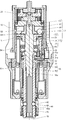
- the clutch mechanism 22 is driven and connected to the first clutch plate 54, which is drive-connected to the rotary drive shaft 18 of the electric motor 12 via the planetary gear mechanism 20, and the solid shaft portion 38, which is the output shaft 16.
- 2 Clutch plate 56 is provided.
- the first clutch plate 54 and the second clutch plate 56 are rotatably arranged around the rotation axis R, respectively.
- the second clutch plate 56 is arranged so as to face the first clutch plate 54.
- a holding groove 58 extending in the radial direction is formed on the facing surface 55 of the first clutch plate 54 facing the second clutch plate 56, and the rotation axis is formed in the holding groove 58.
- the columnar engaging member (engaging protrusion) 60 extending in the radial direction of R is rotatably held.
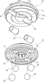
- the second clutch plate 56 has two inner holding holes (small diameter holding holes) 62 penetrating in the direction of the rotation axis R and two inner holding holes (small diameter holding holes) 62 penetrating in the direction of the rotation axis R at positions radially outside the inner holding holes 62.
- Two outer holding holes (large diameter holding holes) 64 are formed.
- the outer holding hole 64 has a larger diameter than the inner holding hole 62.
- a small-diameter spherical engaging member (engaging member) 66 is held in the inner holding hole 62, and the outer holding hole 64 has a larger diameter than the small-diameter spherical engaging member 66.
- the spherical engaging member (engaging member) 68 of the above is held. However, only one engaging member is used, and when assembling the electric screwdriver 1, a small diameter spherical engaging member 66 corresponding to the inner holding hole 62 and a large diameter corresponding to the outer holding hole 64 are used. One of the spherical engaging members 68 is selected and only the selected engaging member is placed in the corresponding holding hole. In FIGS.
- a large-diameter spherical engaging member 68 is selectively arranged in the outer holding hole 64.
- the facing surface 55 of the first clutch plate 54 has an inner side that engages with the small-diameter spherical engaging member 66 when the small-diameter spherical engaging member 66 is arranged in the inner holding hole 62.
- An engaging surface 55a and an outer engaging surface 55b that engages with the large-diameter spherical engaging member 68 when the large-diameter spherical engaging member 68 is arranged in the outer holding hole 64 are formed.
- the inner engaging surface 55a protrudes toward the second clutch plate 56 from the outer engaging surface 55b by the difference in diameter between the small diameter spherical engaging member 66 and the large diameter spherical engaging member 68. ..
- the engaging member 68 is arranged, the height at which the large-diameter spherical engaging member 68 protrudes from the second clutch plate 56 is the same.
- the clutch mechanism 22 further includes a displacement member 70 displaced in the direction of the rotation axis R with respect to the solid shaft portion 38 of the second clutch plate 56 and the output shaft 16.
- the displacement member 70 includes a slide member 72 that slides on the outer peripheral surface 38a of the solid shaft portion 38 in the direction of the rotation axis R, and a thrust receiving member 76 that is made rotatable with respect to the slide member 72 by the bearing 74. It has a sensor pin 80 that is pressed by a thrust receiving member 76 by a spring 78 and is arranged so as to be displaced in the direction of the rotation axis R together with the slide member 72 and the thrust receiving member 76.
- the thrust receiving member 76 of the displacement member 70 is pressed toward the second clutch plate 56 by the clutch spring 82 via the transmission pin 84. Since the large-diameter spherical engaging member 68 is in contact with the engaging surface 72a of the slide member 72, the side of the first clutch plate 54 and the cylindrical engaging member 60 via the thrust receiving member 76 and the slide member 72. Is being urged to.
- the cylindrical engaging member 60 and the spherical engaging member 68 are engaged on a curved surface, and in a state where the rotational torque is transmitted, the spherical engaging member 68 is in the direction of the rotation axis R from the cylindrical engaging member 60.
- the force is applied in the direction away from the columnar engaging member 60.
- the spherical engaging member 68 is urged toward the first clutch plate 54 by the clutch spring 82. Therefore, while the force in the direction of the rotation axis R received by the spherical engagement member 68 from the columnar engagement member 60 is within the range of the urging force of the clutch spring 82, the spherical engagement member 68 is in the direction of the rotation axis R.
- the state in which the columnar engaging member 60 and the spherical engaging member 68 are engaged in the rotational direction and the rotational torque is transmitted is maintained without being displaced.
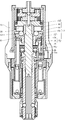
- the spherical engaging member 68 When a load equal to or greater than a predetermined maximum rotational torque acts on the clutch mechanism 22, the spherical engaging member 68 is pushed in the direction of the rotation axis R by the cylindrical engaging member 60, and the clutch spring 82 is compressed together with the displacement member 70. It is displaced in a direction away from the first clutch plate 54 (downward as seen in the figure). As shown in FIG. 7, when the spherical engaging member 68 is displaced to a state where it completely rides on the cylindrical engaging member 60, the cylindrical engaging member 60 and the spherical engaging member 68 are engaged in the rotational direction. Is released, and the transmission of rotational torque from the first clutch plate 54 to the second clutch plate 56 is also temporarily released.
- the sensor pin 80 of the displacement member 70 enters between the light emitting portion and the light receiving portion 26a of the photoelectric sensor 26 for braking. As a result, the sensor pin 80 partially blocks the light projected from the light emitting unit toward the light receiving unit 26a.
- the calculation unit 30 can detect the position of the sensor pin 80 between the light emitting unit and the light receiving unit 26a based on the output value of the brake photoelectric sensor 26. When the output value of the brake photoelectric sensor 26 exceeds a predetermined release determination reference value, the calculation unit 30 determines that the clutch mechanism 22 has released the transmission of the rotational torque, and stops driving the electric motor 12.
- the columnar engaging member 60 and the spherical engaging member 68 rub against each other while receiving a relatively large force. Therefore, as the electric screwdriver 1 is used repeatedly, the columnar engaging member 60 and the spherical engaging member 68 gradually wear. Further, since movements of rubbing against each other may occur between the spherical engaging member 68 and the slide member 72 and between the slide member 72 and the thrust receiving member 76, these members may also wear. When the members constituting the clutch mechanism 22 are worn in this way, the sensor pin 80 is released when the spherical engaging member 68 rides on the cylindrical engaging member 60 and the transmission of the rotational torque by the clutch mechanism 22 is released.
- the amount of entry between the light emitting portion and the light receiving portion 26a of the photoelectric sensor 26 for the brake becomes smaller.
- the calculation unit 30 monitors the output value of the photoelectric photoelectric sensor 26 for the brake, and the sensor pin 80 is located between the light emitting unit and the light receiving unit 26a based on the output value of the photoelectric sensor 26 for the brake. The position is detected to determine the wear state of the clutch mechanism 22.
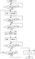
- the wear state of the electric screwdriver 1 is specifically determined by the operation shown in the flowchart of FIG.
- the calculation unit 30 is activated (S10).
- the calculation unit 30 monitors the output value of the start photoelectric sensor 24, and when the output value of the start photoelectric sensor 24 becomes larger than a predetermined start threshold value (S12), the driver bit attached to the tool attachment unit 14 is released. It is determined that the motor 12 has been pushed in, and the rotary drive of the electric motor 12 is started (S14).
- the calculation unit 30 monitors the output value of the brake photoelectric sensor 26, and the output value of the brake photoelectric sensor 26 becomes larger than the predetermined release determination reference value (S16) and then equal to or less than the release determination reference value.
- the maximum output value having the largest difference from the release determination reference value among the output values during that period is stored in the memory 34 (S18), and the drive of the electric motor 12 is stopped (S17). S20).
- the calculation unit 30 monitors the output value of the start photoelectric sensor 24 again, and when the output value of the start photoelectric sensor 24 changes to a value larger than the start threshold value (S22), the brake is stored in the memory 34.
- the maximum output value of the photoelectric sensor 26 is compared with a predetermined wear determination reference value (S24). When the maximum output value rises to the wear judgment reference value and exceeds the wear judgment reference value, it is determined that the sensor pin 80 is sufficiently displaced and the clutch mechanism 22 is not worn so much.
- the drive of the electric motor 12 is restarted (S14).
- the maximum output value has not reached the wear determination reference value and is therefore smaller than the wear determination reference value, it is determined that the sensor pin 80 is not sufficiently displaced and the clutch mechanism 22 is worn.
- an error signal is issued (S26).
- the error display unit 36 emits light so as to indicate that the wear of the clutch mechanism 22 has progressed by a certain amount or more. In this case, the driving of the electric motor 12 is not started.
- the output value of the start photoelectric sensor 24 and the brake photoelectric sensor 26 may decrease when the amount of light received by the light receiving unit 26a decreases.
- the driving of the electric motor 12 is started when the output value of the start photoelectric sensor 24 changes to a value smaller than the start threshold value. Further, when the output value of the brake photoelectric sensor 26 changes to a value smaller than the release determination reference value and then returns to a value equal to or higher than the release determination reference value, it is determined that the clutch mechanism 22 has been released, and the output during that period. If the minimum output value having the largest difference from the release judgment reference value among the values does not reach the wear judgment reference value or less and is larger than the wear judgment reference value, an error signal is issued.
- the determination of the wear state does not only indicate two states of whether or not the wear exceeds a certain amount, but also determines the progress of the wear in three or more stages or analog based on the output value of the photoelectric sensor 26 for the brake. It may be shown steplessly.
- a small-diameter spherical engaging member 66 can be selectively arranged and assembled in the inner holding hole 62.
- the small-diameter spherical engaging member 66 arranged in the inner holding hole 62 engages with the inner engaging surface 55a protruding from the outer engaging surface 55b on the facing surface 55 of the first clutch plate 54. It fits.
- the displacement member 70 of the clutch mechanism 22 is in the same position as in the state of FIG. 3 in which the large-diameter spherical engaging member 68 is arranged.
- the position of the sensor pin 80 with respect to the brake photoelectric sensor 26 is also the same.
- the displacement amount of the displacement member 70 is smaller than that in the state of FIG. 7 in which the large-diameter spherical engaging member 68 is arranged. Therefore, the amount of the sensor pin 80 entering between the light emitting portion and the light receiving portion 26a of the photoelectric sensor 26 for the brake is smaller than that in the case of FIG. Therefore, when the small-diameter spherical engaging member 66 is selectively arranged, the release determination reference value and the wear determination reference value are smaller than when the large-diameter spherical engaging member 68 is selectively arranged. Is set to.
- the clutch mechanism 22 is released with a smaller rotational torque when the positions where the spherical engaging members 66 and 68 are engaged with the cylindrical engaging member 60 are inward in the radial direction with respect to the rotation axis R. It will be. Therefore, in the electric screwdriver 1, when the small-diameter spherical engaging member 66 is selectively arranged in the inner holding hole 62, the large-diameter spherical engaging member 68 is selectively arranged in the outer holding hole 64. The clutch mechanism 22 is released with a smaller rotational torque than in the case.
- the maximum rotational torque that can be transmitted by the clutch mechanism 22 is large depending on whether the large-diameter spherical engaging member 68 is arranged in the outer holding hole 64 or the small-diameter spherical engaging member 66 is arranged in the inner holding hole 62. It is possible to change the torque.
- the sizes of the inner holding hole and the outer holding hole may be the same, and the engaging members arranged in the inner holding hole and the outer holding hole may be the same. In this case, since the positions of the engaging members in the radial direction in which they engage with the columnar engaging member 60 are different, the maximum rotational torque can be set to different sizes.
- the small-diameter holding hole and the large-diameter holding hole may be formed at the same position in the radial direction.
- the maximum rotational torque can be set to different sizes.
- the positions of the holding holes in the radial direction are different and the sizes of the engaging members are also different, the difference in the maximum rotational torque that can be set can be made larger.
- the columnar engaging member constituting the engaging protrusion may be a member having another shape such as a spherical shape instead of a cylindrical shape, or may be integrally formed with the first clutch plate and formed from the first clutch plate. It may be a protruding part. Further, the columnar engaging member is driven and connected to the output shaft side, and the engaging member is driven and connected to the input shaft side so that the displacement member is displaced to the input shaft side when the clutch mechanism is released. It can also be configured.
- the power tool according to the present invention is described by taking an electric screwdriver having an electric motor as a drive unit as an example, but for example, an electric tool other than the electric screwdriver such as an electric drill or an electric grinding machine. It can also be used as another power tool such as an air tool whose drive unit is an air motor.
- the clutch mechanism can also be used in mechanical structures other than power tools.
Landscapes
- Engineering & Computer Science (AREA)
- General Engineering & Computer Science (AREA)
- Mechanical Engineering (AREA)
- Details Of Spanners, Wrenches, And Screw Drivers And Accessories (AREA)
- One-Way And Automatic Clutches, And Combinations Of Different Clutches (AREA)
Priority Applications (4)
| Application Number | Priority Date | Filing Date | Title |
|---|---|---|---|
| DE112020005195.1T DE112020005195T5 (de) | 2019-10-28 | 2020-09-11 | Kupplungsmechanismus und Elektrowerkzeug |
| CN202080075119.9A CN114599893B (zh) | 2019-10-28 | 2020-09-11 | 离合器机构及动力工具 |
| JP2021554150A JP7220304B2 (ja) | 2019-10-28 | 2020-09-11 | クラッチ機構および動力工具 |
| US17/730,799 US12129897B2 (en) | 2019-10-28 | 2022-04-27 | Clutch mechanism and power tool |
Applications Claiming Priority (2)
| Application Number | Priority Date | Filing Date | Title |
|---|---|---|---|
| JP2019195448 | 2019-10-28 | ||
| JP2019-195448 | 2019-10-28 |
Related Child Applications (1)
| Application Number | Title | Priority Date | Filing Date |
|---|---|---|---|
| US17/730,799 Continuation US12129897B2 (en) | 2019-10-28 | 2022-04-27 | Clutch mechanism and power tool |
Publications (1)
| Publication Number | Publication Date |
|---|---|
| WO2021084936A1 true WO2021084936A1 (ja) | 2021-05-06 |
Family
ID=75714632
Family Applications (1)
| Application Number | Title | Priority Date | Filing Date |
|---|---|---|---|
| PCT/JP2020/034445 Ceased WO2021084936A1 (ja) | 2019-10-28 | 2020-09-11 | クラッチ機構および動力工具 |
Country Status (5)
| Country | Link |
|---|---|
| US (1) | US12129897B2 (https=) |
| JP (1) | JP7220304B2 (https=) |
| CN (1) | CN114599893B (https=) |
| DE (1) | DE112020005195T5 (https=) |
| WO (1) | WO2021084936A1 (https=) |
Cited By (1)
| Publication number | Priority date | Publication date | Assignee | Title |
|---|---|---|---|---|
| WO2024262210A1 (ja) * | 2023-06-19 | 2024-12-26 | パナソニック株式会社 | トルククラッチ機構及び電動工具 |
Citations (4)
| Publication number | Priority date | Publication date | Assignee | Title |
|---|---|---|---|---|
| JPS56120828A (en) * | 1980-02-11 | 1981-09-22 | Hilti Ag | Overload clutch |
| JPS59105375U (ja) * | 1982-12-29 | 1984-07-16 | 日立工機株式会社 | クラツチ式締付工具 |
| JPH0219479U (https=) * | 1988-07-22 | 1990-02-08 | ||
| US20140073440A1 (en) * | 2012-09-11 | 2014-03-13 | Comer Industries S.P.A. | Torque Limiting Device, Particularly for Power Transmission Elements |
Family Cites Families (16)
| Publication number | Priority date | Publication date | Assignee | Title |
|---|---|---|---|---|
| JPS59105375A (ja) | 1982-12-08 | 1984-06-18 | Nec Corp | 半導体装置 |
| JPS613862U (ja) | 1984-06-12 | 1986-01-10 | 株式会社竹中工務店 | ユニツトバス |
| SU1471000A1 (ru) * | 1986-02-26 | 1989-04-07 | М.П.Шигакарёв | Предохранительна шарикова муфта |
| GB8620214D0 (en) * | 1986-08-20 | 1986-10-01 | Gib Precision Ltd | Torque limited clutch |
| SU1700306A1 (ru) * | 1989-12-29 | 1991-12-23 | М. П. Шишкарев | Предохранительна фрикционна муфта |
| JPH0737817B2 (ja) * | 1991-12-10 | 1995-04-26 | 株式会社椿本エマソン | 回転方向によって異なるトリップトルクを有するボールクラッチ |
| JPH0737817A (ja) | 1993-06-28 | 1995-02-07 | Sony Corp | プラズマ計測用プローブ及びこれを用いたプラズマ計測方法 |
| DE19611622C1 (de) * | 1996-03-25 | 1997-07-24 | Walterscheid Gmbh Gkn | Drehmomentbegrenzungskupplung |
| WO2004024398A1 (en) | 2002-09-13 | 2004-03-25 | Black & Decker Inc | Rotary tool |
| JP2006118645A (ja) * | 2004-10-22 | 2006-05-11 | Ntn Corp | 回転伝達装置 |
| DE112010003617T5 (de) * | 2009-09-11 | 2012-08-23 | Ntn Corp. | Elektrofahrzeug |
| US9039538B2 (en) | 2013-10-21 | 2015-05-26 | Moog Inc. | Non-chattering ball detent torque limiter |
| JP6178283B2 (ja) | 2014-05-30 | 2017-08-09 | ツバキ山久チエイン株式会社 | 過負荷保護装置 |
| JP6539156B2 (ja) | 2015-08-27 | 2019-07-03 | 日東工器株式会社 | 空気式工具 |
| DE112016003913B4 (de) | 2015-08-31 | 2022-05-25 | Nitto Kohki Co., Ltd. | Angetriebenes Werkzeug |
| JP2017061973A (ja) * | 2015-09-24 | 2017-03-30 | Ntn株式会社 | 逆入力防止クラッチ |
-
2020
- 2020-09-11 JP JP2021554150A patent/JP7220304B2/ja active Active
- 2020-09-11 DE DE112020005195.1T patent/DE112020005195T5/de active Granted
- 2020-09-11 WO PCT/JP2020/034445 patent/WO2021084936A1/ja not_active Ceased
- 2020-09-11 CN CN202080075119.9A patent/CN114599893B/zh active Active
-
2022
- 2022-04-27 US US17/730,799 patent/US12129897B2/en active Active
Patent Citations (4)
| Publication number | Priority date | Publication date | Assignee | Title |
|---|---|---|---|---|
| JPS56120828A (en) * | 1980-02-11 | 1981-09-22 | Hilti Ag | Overload clutch |
| JPS59105375U (ja) * | 1982-12-29 | 1984-07-16 | 日立工機株式会社 | クラツチ式締付工具 |
| JPH0219479U (https=) * | 1988-07-22 | 1990-02-08 | ||
| US20140073440A1 (en) * | 2012-09-11 | 2014-03-13 | Comer Industries S.P.A. | Torque Limiting Device, Particularly for Power Transmission Elements |
Cited By (1)
| Publication number | Priority date | Publication date | Assignee | Title |
|---|---|---|---|---|
| WO2024262210A1 (ja) * | 2023-06-19 | 2024-12-26 | パナソニック株式会社 | トルククラッチ機構及び電動工具 |
Also Published As
| Publication number | Publication date |
|---|---|
| US20220252113A1 (en) | 2022-08-11 |
| CN114599893A (zh) | 2022-06-07 |
| CN114599893B (zh) | 2023-08-04 |
| JPWO2021084936A1 (https=) | 2021-05-06 |
| DE112020005195T5 (de) | 2022-09-29 |
| JP7220304B2 (ja) | 2023-02-09 |
| US12129897B2 (en) | 2024-10-29 |
Similar Documents
| Publication | Publication Date | Title |
|---|---|---|
| KR101322216B1 (ko) | 마찰 클러치를 가진 파워 툴 | |
| US6688406B1 (en) | Power tool having a function control mechanism for controlling operation in one of rotary drive and hammering modes | |
| US9636818B2 (en) | Multi-speed cycloidal transmission | |
| JP4160393B2 (ja) | 第一段クラッチ | |
| US7712546B2 (en) | Power tool having torque limiter | |
| US5568849A (en) | Clutch mechanism in power driven screwdriver | |
| US11413737B2 (en) | Hand-held power tool with a mode-setting device | |
| US20100236889A1 (en) | Power Tool | |
| WO2021084936A1 (ja) | クラッチ機構および動力工具 | |
| JP2021066003A (ja) | 動力工具 | |
| US7188557B2 (en) | Tightening tool | |
| JP7710353B2 (ja) | ネジ締め工具 | |
| JP2009012173A (ja) | 手工具装置 | |
| CN103707253B (zh) | 冲击旋转工具 | |
| KR102219738B1 (ko) | 전동공구 | |
| JP5391868B2 (ja) | ねじ締め機 | |
| JP7810895B2 (ja) | 作業機 | |
| JP2025104116A (ja) | フレア形成装置及びフレア形成工具 | |
| JP4448049B2 (ja) | 電動ドライバ | |
| WO2024024250A1 (ja) | 作業機 |
Legal Events
| Date | Code | Title | Description |
|---|---|---|---|
| 121 | Ep: the epo has been informed by wipo that ep was designated in this application |
Ref document number: 20880960 Country of ref document: EP Kind code of ref document: A1 |
|
| ENP | Entry into the national phase |
Ref document number: 2021554150 Country of ref document: JP Kind code of ref document: A |
|
| 122 | Ep: pct application non-entry in european phase |
Ref document number: 20880960 Country of ref document: EP Kind code of ref document: A1 |