WO2021084764A1 - 伸縮部材及びこの伸縮部材を有する使い捨て着用物品 - Google Patents
伸縮部材及びこの伸縮部材を有する使い捨て着用物品 Download PDFInfo
- Publication number
- WO2021084764A1 WO2021084764A1 PCT/JP2019/045424 JP2019045424W WO2021084764A1 WO 2021084764 A1 WO2021084764 A1 WO 2021084764A1 JP 2019045424 W JP2019045424 W JP 2019045424W WO 2021084764 A1 WO2021084764 A1 WO 2021084764A1
- Authority
- WO
- WIPO (PCT)
- Prior art keywords
- sheet
- sheet layer
- elastic
- elastic sheet
- color
- Prior art date
- Legal status (The legal status is an assumption and is not a legal conclusion. Google has not performed a legal analysis and makes no representation as to the accuracy of the status listed.)
- Ceased
Links
Images


Classifications
-
- A—HUMAN NECESSITIES
- A61—MEDICAL OR VETERINARY SCIENCE; HYGIENE
- A61F—FILTERS IMPLANTABLE INTO BLOOD VESSELS; PROSTHESES; DEVICES PROVIDING PATENCY TO, OR PREVENTING COLLAPSING OF, TUBULAR STRUCTURES OF THE BODY, e.g. STENTS; ORTHOPAEDIC, NURSING OR CONTRACEPTIVE DEVICES; FOMENTATION; TREATMENT OR PROTECTION OF EYES OR EARS; BANDAGES, DRESSINGS OR ABSORBENT PADS; FIRST-AID KITS
- A61F13/00—Bandages or dressings; Absorbent pads
- A61F13/15—Absorbent pads, e.g. sanitary towels, swabs or tampons for external or internal application to the body; Supporting or fastening means therefor; Tampon applicators
- A61F13/45—Absorbent pads, e.g. sanitary towels, swabs or tampons for external or internal application to the body; Supporting or fastening means therefor; Tampon applicators characterised by the shape
- A61F13/49—Absorbent pads, e.g. sanitary towels, swabs or tampons for external or internal application to the body; Supporting or fastening means therefor; Tampon applicators characterised by the shape specially adapted to be worn around the waist, e.g. diapers, nappies
- A61F13/49007—Form-fitting, self-adjusting disposable diapers
- A61F13/49009—Form-fitting, self-adjusting disposable diapers with elastic means
- A61F13/4902—Form-fitting, self-adjusting disposable diapers with elastic means characterised by the elastic material
-
- A—HUMAN NECESSITIES
- A61—MEDICAL OR VETERINARY SCIENCE; HYGIENE
- A61F—FILTERS IMPLANTABLE INTO BLOOD VESSELS; PROSTHESES; DEVICES PROVIDING PATENCY TO, OR PREVENTING COLLAPSING OF, TUBULAR STRUCTURES OF THE BODY, e.g. STENTS; ORTHOPAEDIC, NURSING OR CONTRACEPTIVE DEVICES; FOMENTATION; TREATMENT OR PROTECTION OF EYES OR EARS; BANDAGES, DRESSINGS OR ABSORBENT PADS; FIRST-AID KITS
- A61F13/00—Bandages or dressings; Absorbent pads
- A61F13/15—Absorbent pads, e.g. sanitary towels, swabs or tampons for external or internal application to the body; Supporting or fastening means therefor; Tampon applicators
- A61F13/45—Absorbent pads, e.g. sanitary towels, swabs or tampons for external or internal application to the body; Supporting or fastening means therefor; Tampon applicators characterised by the shape
- A61F13/49—Absorbent pads, e.g. sanitary towels, swabs or tampons for external or internal application to the body; Supporting or fastening means therefor; Tampon applicators characterised by the shape specially adapted to be worn around the waist, e.g. diapers, nappies
- A61F13/49001—Absorbent pads, e.g. sanitary towels, swabs or tampons for external or internal application to the body; Supporting or fastening means therefor; Tampon applicators characterised by the shape specially adapted to be worn around the waist, e.g. diapers, nappies having preferential bending zones, e.g. fold lines or grooves
-
- A—HUMAN NECESSITIES
- A61—MEDICAL OR VETERINARY SCIENCE; HYGIENE
- A61F—FILTERS IMPLANTABLE INTO BLOOD VESSELS; PROSTHESES; DEVICES PROVIDING PATENCY TO, OR PREVENTING COLLAPSING OF, TUBULAR STRUCTURES OF THE BODY, e.g. STENTS; ORTHOPAEDIC, NURSING OR CONTRACEPTIVE DEVICES; FOMENTATION; TREATMENT OR PROTECTION OF EYES OR EARS; BANDAGES, DRESSINGS OR ABSORBENT PADS; FIRST-AID KITS
- A61F13/00—Bandages or dressings; Absorbent pads
- A61F13/15—Absorbent pads, e.g. sanitary towels, swabs or tampons for external or internal application to the body; Supporting or fastening means therefor; Tampon applicators
- A61F13/51—Absorbent pads, e.g. sanitary towels, swabs or tampons for external or internal application to the body; Supporting or fastening means therefor; Tampon applicators characterised by the outer layers of the pads
- A61F13/514—Backsheet, i.e. the impermeable cover or layer furthest from the skin
- A61F13/51456—Backsheet, i.e. the impermeable cover or layer furthest from the skin characterised by its properties
- A61F13/51458—Backsheet, i.e. the impermeable cover or layer furthest from the skin characterised by its properties being air-pervious or breathable
-
- A—HUMAN NECESSITIES
- A61—MEDICAL OR VETERINARY SCIENCE; HYGIENE
- A61F—FILTERS IMPLANTABLE INTO BLOOD VESSELS; PROSTHESES; DEVICES PROVIDING PATENCY TO, OR PREVENTING COLLAPSING OF, TUBULAR STRUCTURES OF THE BODY, e.g. STENTS; ORTHOPAEDIC, NURSING OR CONTRACEPTIVE DEVICES; FOMENTATION; TREATMENT OR PROTECTION OF EYES OR EARS; BANDAGES, DRESSINGS OR ABSORBENT PADS; FIRST-AID KITS
- A61F13/00—Bandages or dressings; Absorbent pads
- A61F13/15—Absorbent pads, e.g. sanitary towels, swabs or tampons for external or internal application to the body; Supporting or fastening means therefor; Tampon applicators
- A61F13/51—Absorbent pads, e.g. sanitary towels, swabs or tampons for external or internal application to the body; Supporting or fastening means therefor; Tampon applicators characterised by the outer layers of the pads
- A61F13/514—Backsheet, i.e. the impermeable cover or layer furthest from the skin
- A61F13/51496—Backsheet, i.e. the impermeable cover or layer furthest from the skin having visual effects
-
- A—HUMAN NECESSITIES
- A61—MEDICAL OR VETERINARY SCIENCE; HYGIENE
- A61F—FILTERS IMPLANTABLE INTO BLOOD VESSELS; PROSTHESES; DEVICES PROVIDING PATENCY TO, OR PREVENTING COLLAPSING OF, TUBULAR STRUCTURES OF THE BODY, e.g. STENTS; ORTHOPAEDIC, NURSING OR CONTRACEPTIVE DEVICES; FOMENTATION; TREATMENT OR PROTECTION OF EYES OR EARS; BANDAGES, DRESSINGS OR ABSORBENT PADS; FIRST-AID KITS
- A61F13/00—Bandages or dressings; Absorbent pads
- A61F13/15—Absorbent pads, e.g. sanitary towels, swabs or tampons for external or internal application to the body; Supporting or fastening means therefor; Tampon applicators
- A61F13/45—Absorbent pads, e.g. sanitary towels, swabs or tampons for external or internal application to the body; Supporting or fastening means therefor; Tampon applicators characterised by the shape
- A61F13/49—Absorbent pads, e.g. sanitary towels, swabs or tampons for external or internal application to the body; Supporting or fastening means therefor; Tampon applicators characterised by the shape specially adapted to be worn around the waist, e.g. diapers, nappies
- A61F2013/49088—Absorbent pads, e.g. sanitary towels, swabs or tampons for external or internal application to the body; Supporting or fastening means therefor; Tampon applicators characterised by the shape specially adapted to be worn around the waist, e.g. diapers, nappies characterized by the leg opening
Definitions
- the present invention relates to an elastic member having an elastic structure in which an elastic sheet such as an elastic film is sandwiched between a first sheet layer and a second sheet layer, and a disposable wearable article having the elastic member.
- the elastic sheet is laminated between the first sheet layer and the second sheet layer, and the elastic sheet is stretched in the expansion / contraction direction, and the first sheet layer and the second sheet are formed.
- the layers are a large number of point-shaped sheet joints arranged at intervals in the expansion / contraction direction and the direction orthogonal to the expansion / contraction direction, and are joined through joint holes formed in the elastic sheet. Then, in the natural length state of this elastic member, as the elastic sheet contracts between the sheet joints, the interval between the sheet joints becomes narrower, and between the sheet joints in the first sheet layer and the second sheet layer. Folds that extend in the direction intersecting the expansion and contraction direction are formed.
- the elastic sheet extends between the sheet joints, the distance between the sheet joints and the folds in the first sheet layer and the second sheet layer expand, and the first sheet layer and the second sheet layer are completely extended. Elastic elongation is possible up to the unfolded state. Further, at least in a state of being extended to some extent, the vent hole is opened by separating the edge of the joint hole from the outer peripheral edge of the sheet joint portion in the expansion / contraction direction.
- the elastic members used in disposable wear articles are not only functional requirements such as breathability, fit and flexibility, but also cloth. A close appearance is also required. Therefore, as the first sheet layer and the second sheet layer, a non-woven fabric which is a thin and flexible material is suitable.
- the shape of the ventilation holes can be seen through slightly, depending on the user. There was a risk that the appearance would be unfavorable.
- Japanese Unexamined Patent Publication No. 2016-189932 Japanese Unexamined Patent Publication No. 2015-202982 JP-A-2016-140477 Japanese Unexamined Patent Publication No. 2016-189931 Japanese Unexamined Patent Publication No. 2016-189933 JP-A-2017-0642224 JP-A-2017-148169 Japanese Unexamined Patent Publication No. 2017-225508
- a main object of the present invention is to provide an elastic member having an excellent aesthetic appearance while having a ventilation hole in the elastic sheet.
- the telescopic members that have solved the above problems and the disposable wearable articles having the telescopic members are as follows.
- An elastic sheet is interposed between the outer sheet layer having an exposed portion and the lower sheet layer, and the outer sheet layer and the lower sheet layer penetrate the elastic sheet at a large number of sheet joints arranged at intervals. It has an elastic sheet telescopic structure that is joined through a joint hole or through the elastic sheet.
- the region having the elastic sheet stretchable structure has a stretchable region that is contracted in the stretchable direction due to the shrinkage of the elastic sheet and is expandable in the stretchable direction.
- the edge of the joint hole has a ventilation hole that opens away from the outer peripheral edge of the sheet joint portion in the expansion / contraction direction.
- the color of the outer surface of the elastic sheet and the color of the portion of the outer surface of the lower sheet layer seen through the ventilation holes can be seen through the outer sheet layer.
- the color difference ⁇ E between the color of the outer surface of the elastic sheet and the color of the outer surface of the lower sheet layer is 5 or less.
- the elastic sheet has a light transmittance of 40 to 60%.
- the telescopic member of the first aspect is a light transmittance of 40 to 60%.
- the light transmittance of the lower sheet layer is 0.5 to 2.0 times the light transmittance of the elastic sheet.
- the telescopic member of the first or second aspect is 0.5 to 2.0 times the light transmittance of the elastic sheet.
- the light transmittance of the lower sheet layer and the elastic sheet is preferably within the range of this embodiment.
- the outer sheet layer is a perforated non-woven fabric provided with holes penetrating the front and back surfaces arranged at intervals.
- the color difference ⁇ E between the color of the outer surface of the elastic sheet and the color of the outer surface of the outer sheet layer is 5 or less.
- the outer sheet layer uniformly covers the outside of the elastic sheet, even if the color difference with respect to the elastic sheet is large, it does not directly affect the appearance of the vents, but in order to improve the air permeability of the outer sheet layer.
- the holes of the perforated non-woven fabric are conspicuous, and some users may feel that the appearance is not so preferable.
- the outer sheet layer, the elastic sheet, and the lower sheet layer are sheets having an outer surface having a whiteness of 60 to 80%, respectively.
- the outer sheet layer is a non-woven fabric having a fiber fineness of 1.0 to 6.0 dtex and a basis weight of 15 to 25 g / m 2.
- the outer sheet layer is a non-woven fabric within the range of this embodiment, but such a non-woven fabric has a high light transmittance (for example, 50% or more), so that the ventilation holes can be seen through. It will be easier. Therefore, the above-mentioned color difference becomes particularly significant when applied when it has an outer sheet layer as in this embodiment.
- the expansion and contraction region has the ventilation holes opened in a state of natural length.
- the vent hole is a portion where the edge of the joint hole is formed apart from the outer peripheral edge of the sheet joint portion in the expansion / contraction direction, the vent hole is deformed by the elongation of the elastic sheet and becomes larger as it approaches the expanded state. Further, depending on the shape of the sheet joint portion (for example, circular shape), the edge of the joint hole and the outer peripheral edge of the sheet joint portion may be in close contact with each other in a natural length state, and a ventilation hole may not be formed. Even in this case, in a state of being stretched to some extent, such as in a mounted state, the joint holes are stretched in the expansion / contraction direction, so that ventilation holes are opened at least on both sides of the sheet joint in the expansion / contraction direction.
- the edge of the joint hole and the outer peripheral edge of the sheet joint portion may be in close contact with each other in a natural length state, and a ventilation hole may not be formed. Even in this case, in a state of being stretched to some extent, such as in a mounted state, the joint holes are stretched in the
- the elastic region has a natural length and the vent holes are opened as in the present elastic member.
- this type of product is sold in its natural length, having an opening in the elastic sheet in its natural length may affect the appearance of the product before use. Therefore, each of the above-described aspects is particularly significant when applied to a structure in which the ventilation holes are opened in a state of natural length.
- ⁇ 8th aspect> An integrated exterior body from the front body to the back body, or an exterior body separately provided on the front body and the back body, and an interior body attached to the middle part in the width direction of the exterior body and covering both front and rear sides of the crotch part.
- the exterior body on at least one of the front body and the back body covers an elastic sheet according to any one of the first to seventh aspects over a width direction range corresponding to the side seal portions in at least a part range in the front-rear direction.
- An elastic member having an elastic structure so that the elastic direction of the elastic region is the width direction.
- the above-mentioned elastic member is suitable for the outer body of a pants-type disposable wear article as in this embodiment.
- the elastic sheet has ventilation holes, it has advantages such as being an aesthetically pleasing elastic member.
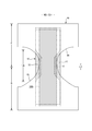
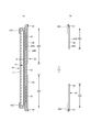
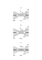
- FIG. 1 is a cross-sectional view taken along the line AA of FIG. It is a cross-sectional view of BB of FIG. It is a plan view (outer surface side) of the pants type disposable diaper in the unfolded state.
- A) is a sectional view taken along the line CC of FIG.
- FIG. 7B is a sectional view taken along the line EE of FIG.
- (A) is a plan view of a main part of the expansion / contraction region
- (b) is a cross-sectional view taken along the line DD of (a)
- (c) is a cross-sectional view taken in a mounted state
- (d) is a cross-sectional view taken in a natural length state.
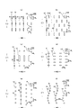
- It is a top view which shows various shapes of a sheet joint part.
- It is a top view of the expansion and contraction area in the expanded state.
- (A) is a cross-sectional view taken along the line DD of FIG. 12, and (b) is a cross-sectional view taken along the line in the natural length state. It is a top view of the expansion and contraction area in the expanded state. It is a top view which shows the main part of the expansion and contraction area in an expanded state in an enlarged manner. It is a top view which shows the main part of the expansion and contraction region in a natural length state in an enlarged manner. It is sectional drawing which shows roughly the cross section of the main part of the exterior body extended to some extent. It is sectional drawing which shows roughly the cross section of the main part of the exterior body extended to some extent. It is the schematic of the ultrasonic sealing apparatus.
- (A) is a plan view of a main part of a non-stretchable region
- (b) is a cross-sectional view taken along the line DD of (a)
- (c) is a cross-sectional view taken in a mounted state
- (d) is a cross-sectional view taken in a natural length state.
- It is a main part plan view of a non-stretchable region.
- It is a main part enlarged plan view which shows various patterns of the hole of a perforated non-woven fabric.
- It is a main part enlarged plan view which shows various patterns of the hole of a perforated non-woven fabric.
- the dotted pattern portion in the figure shows an adhesive as a joining means for joining each component located on the front side and the back side, and is a solid, bead, curtain, summit or spiral coating of hot melt adhesive, or
- the fixed portion of the elastic member is formed by pattern coating (transfer of hot melt adhesive by the letterpress method) or by coating the elastic member on the outer peripheral surface of the elastic member such as comb gun or sure wrap coating instead of or together with this. It is a thing.
- the hot melt adhesive include EVA type, adhesive rubber type (elastomer type), olefin type, polyester / polyamide type and the like, but they can be used without particular limitation.
- a joining means for joining each component a means by material welding such as a heat seal or an ultrasonic seal can also be used.
- non-woven fabric in the following description, a known non-woven fabric can be appropriately used depending on the site and purpose.
- the constituent fibers of the non-woven fabric include olefin-based fibers such as polyethylene and polypropylene, polyester-based and polyamide-based synthetic fibers (including single-component fibers and composite fibers such as core sheaths), as well as recycled rayon and cupra. Fibers, natural fibers such as cotton, and the like can be selected without particular limitation, and these can be mixed and used. In order to increase the flexibility of the non-woven fabric, it is preferable that the constituent fibers are crimped fibers.
- the non-woven fabric generally has a short fiber non-woven fabric, a long fiber non-woven fabric, a spunbond non-woven fabric, a melt blown non-woven fabric, a spunlace non-woven fabric, a thermal bond (air-through) non-woven fabric, and a needle punch depending on the fiber length, the sheet forming method, the fiber bonding method, and the laminated structure.
- Laminated non-woven fabric means that it is manufactured as an integral non-woven fabric including all layers and fiber-bonded processing is performed over all layers, and a plurality of separately manufactured non-woven fabrics are attached by a joining means such as a hot melt adhesive. Does not include combined items.
- FIGS. 1 to 6 show pants-type disposable diapers.
- the reference numeral LD vertical direction
- WD indicates the width direction.
- This pants-type disposable diaper (hereinafter, also simply referred to as a diaper) has an outer body 20 forming a front body F and a back body B, and an inner body 10 fixed and integrated to the inner surface of the outer body 20.
- the interior body 10 is formed by interposing an absorber 13 between the liquid-permeable top sheet 11 and the liquid-impermeable sheet 12.
- the interior body 10 and the exterior body 20 are joined to the front body F and the back body B.
- the waist opening and the left and right sides are formed by folding at the center of the front-rear direction LD (longitudinal direction), which is the boundary between the two, and joining the both side portions to each other by heat welding or hot melt adhesive to form the side seal portion 21.
- LD longitudinal direction
- the interior body 10 has a structure in which an absorber 13 is interposed between a top sheet 11 and a liquid-impermeable sheet 12 made of polyethylene or the like, and has a top. It absorbs and retains the excrement liquid that has passed through the sheet 11.
- the planar shape of the interior body 10 is not particularly limited, but it is generally substantially rectangular as shown in FIG.
- the top sheet 11 that covers the front side (skin side) of the absorber 13 is perforated (having holes formed by needle sticking or punching) or non-perforated (having fiber gaps, but needle sticking or punching).
- Non-woven fabrics hose that do not have holes formed by), perforated plastic sheets, and the like are preferably used.
- liquid-impermeable sheet 12 that covers the back side (non-skin contact side) of the absorber 13
- a liquid-impermeable plastic sheet such as polyethylene or polypropylene
- a microporous sheet obtained by melt-kneading an inorganic filler in an olefin resin such as polyethylene or polypropylene to form a sheet and then stretching it in a uniaxial or biaxial direction can be preferably used.
- the absorber 13 is basically a known material, for example, a stack of pulp fibers, an aggregate of filaments such as cellulose acetate, or a non-woven fabric, and a highly absorbent polymer is mixed or fixed as necessary. Can be used.
- the absorber 13 can be packaged with a liquid-permeable and liquid-retaining packaging sheet 15 such as crepe paper, if necessary, in order to retain the shape and polymer.
- the shape of the absorber 13 is formed in a substantially hourglass shape having a constricted portion 13N narrower than both front and rear sides in the crotch portion.
- the size of the constricted portion 13N can be appropriately determined, but the length of the constricted portion 13N in the front-rear direction can be about 20 to 50% of the total length of the diaper, and the width of the narrowest portion is 40 of the total width of the absorber 13. It can be about 60%.
- the planar shape of the interior body 10 is substantially rectangular, the portion of the interior body 10 corresponding to the constricted portion 13N of the absorber 13 does not have the absorber 13.
- the absorber side portion 17 is formed.
- the liquid-impermeable sheet 12 is folded back together with the top sheet 11 on both sides of the absorber 13 in the width direction.
- the liquid impermeable sheet 12 it is desirable to use an opaque sheet so that brown color such as defecation and urine does not appear.
- the opacity a plastic in which pigments such as calcium carbonate, titanium oxide, zinc oxide, white carbon, clay, talc, and barium sulfate and a filler are added and formed into a film is preferably used.
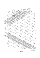
- Rising gathers 60 that fit around the legs are formed on both sides of the interior body 10. As shown in FIGS. 5 and 6, the rising gather 60 has a fixed portion 61 fixed to the side portion of the back surface of the interior body 10, and the interior body 10 from the fixed portion 61 via the side of the interior body 10. With the main body 62 extending to the side of the surface of the main body 62 and the front and rear ends of the main body 62 in an inverted state, hot melt adhesive 65b or the like is applied to the side of the surface of the interior body 10 (top sheet 11 in the illustrated example). It has an inverted portion 63 that is fixed and formed, and a free portion 64 that is formed so that the space between the inverted portions 63 is not fixed.
- Each of these parts is formed of a gather sheet 65 made by folding a sheet such as a non-woven fabric into a double sheet.
- the gather sheet 65 is attached to the entire interior body 10 in the front-rear direction, the inverted portion 63 is provided on the front side and the rear side of the non-absorbent body side portion 17, and the free portion 64 is provided on both front and rear sides of the non-absorbent body side portion 17. It has been postponed.
- a gather elastic member 66 is arranged at the tip of a free portion or the like. The gather elastic member 66 is for raising the free portion 64 by the elastic contraction force as shown in FIG. 5 in the product state.
- the fixed structure of the gathered elastic member 66 and the gathered sheet 65 is not particularly limited, and as in the examples shown in FIGS. 5 and 6, for example, except for the lodging portion 63, the gathered elastic member 66 is located at the position of the gathered elastic member 66 via a hot melt adhesive.
- the gather elastic member 66 is adhesively fixed to the gather sheet 65 and the facing surfaces of the gather sheet 65 are joined, there is no hot melt adhesive at the position of the gather elastic member 66 in the inverted portion 63, and therefore the gather elasticity.
- a structure can be adopted in which the member 66 and the gather sheet 65 are not adhered to each other, and the facing surfaces of the gather sheet 65 are not joined at the position where the gather elastic member 66 is held.
- the gather elastic member 66 commonly used materials such as styrene rubber, olefin rubber, urethane rubber, ester rubber, polyurethane, polyethylene, polystyrene, styrene butadiene, silicone, and polyester can be used. Further, in order to make it difficult to see from the outside, it is preferable to arrange the thickness at 925 dtex or less, the tension at 150 to 350%, and the interval at 7.0 mm or less. As the gather elastic member 66, a tape-shaped member having a certain width may be used in addition to the elongated shape as shown in the illustrated example.
- non-woven fabrics can be used as the gather sheet 65, but in particular, in order to prevent stuffiness, it is preferable to use a non-woven fabric having a reduced basis weight and excellent breathability. Furthermore, regarding the gather sheet 65, in order to prevent the permeation of urine and the like, prevent fogging, and enhance the feel (dry feeling) on the skin, silicone-based, paraffin metal-based, alkylchromic chloride-based water repellents, etc. It is desirable to use a water-repellent treated non-woven fabric coated with.
- the back surface of the interior body 10 is joined to the inner surface of the exterior body 20 by a hot melt adhesive or the like in the inner / outer fixed region 10B (diagonal line region).
- the inside / outside fixed region 10B can be appropriately defined and can be almost the entire width direction WD of the interior body 10, but it is preferable that both ends in the width direction are not fixed to the exterior body 20.
- the exterior body 20 has at least a waist circumference T of the front body F and a waist circumference T of the back body B, and in the illustrated example, between the waist circumference T of the front body F and the waist circumference T of the back body B. It further has an intermediate portion L which is a range in the front-rear direction of the above. As shown in the illustrated example, the exterior body 20 may have the side edge of the exterior body 20 located at the center side in the width direction of the side edge of the interior body 10 in the crotch portion, or may be located outside in the width direction.
- the first sheet layer 20A and the second sheet layer are as shown in FIGS. 2 and 4 to 6, except for the middle portion L in the front-rear direction and the waist end portion 23.
- An elastic sheet 30 is interposed between the 20Bs, and as shown in FIG. 9 and the like, the first sheet layer 20A and the second sheet layer 20B are arranged at a large number of sheet joints 40 at intervals. It has an elastic sheet telescopic structure 20X joined through a joint hole 31 penetrating the elastic sheet 30.
- the region having the elastic sheet expansion / contraction structure is contracted in the width direction due to the contraction of the elastic sheet 30 and is expandable in the width direction (that is, the expansion / contraction direction ED becomes the width direction WD of the diaper).
- the planar shape of the exterior body 20 is formed by concave leg circumference lines 29 so that both side edges in the width direction of the intermediate portion L form leg openings, respectively, and has a shape similar to an hourglass as a whole.
- the exterior body 20 may be individually formed by the front body F and the back body B, and may be arranged so as to be separated from each other in the front-rear direction LD of the diaper at the crotch portion.
- the waist end portion 23 in order to strengthen the tightening of the waist end portion 23, the waist end portion 23 is not provided with the elastic sheet elastic structure 20X, and the waist end portion 23 is expanded and contracted by the conventional elongated waist portion elastic member 24.
- the elastic sheet telescopic structure 20X may extend to the waist end 23, if necessary, as shown in FIGS. 7 and 8.
- the waist elastic member 24 is an elongated elastic member such as a plurality of elastic threads arranged at intervals in the front-rear direction LD, and gives an elastic force so as to tighten around the waist of the body.
- the waist elastic members 24 are not substantially arranged as a bundle at close intervals, but are three or more at intervals of about 3 to 8 mm in the front-rear direction so as to form a predetermined expansion / contraction zone. , Preferably 5 or more are arranged.
- the elongation rate at the time of fixing the waist elastic member 24 can be appropriately determined, but in the case of a normal adult, it can be about 230 to 320%.
- thread rubber is used in the illustrated example, but other elongated elastic members such as flat rubber may be used.
- an elastic sheet 30 may be provided at the waist end 23, and an elongated waist elastic member 24 may be provided at a position overlapping the elastic sheet 30 to form an elastic structure composed of both elastic members.
- the edge portion of the leg opening in the exterior body 20 is not provided with the elongated elastic member extending along the leg opening, but is located at a position overlapping the elastic sheet 30 in the edge portion or the edge.
- An elongated elastic member may be provided instead of the elastic sheet 30 of the portion.
- the elastic sheet elastic structure 20X is not provided in the intermediate portion L between the waist circumference T of the front body F and the waist circumference T of the back body B, or the front body.
- An elastic sheet elastic structure 20X is continuously provided in the front-rear direction LD from the inside of the waist circumference T of F through the middle portion L to the inside of the waist circumference T of the back body B, or either the front body F or the back body B is provided.
- Appropriate deformation is also possible, such as providing an elastic sheet telescopic structure 20X only on the surface.
- the region of the exterior body 20 having the elastic sheet telescopic structure 20X has a stretchable region that can be stretched in the width direction WD.
- the elastic sheet 30 contracts in the width direction WD due to the contraction force of the elastic sheet 30, and can expand in the width direction WD. More specifically, in a state where the elastic sheet 30 is extended in the width direction WD, the elastic sheet 30 is separated from each other in the width direction WD and the front-rear direction LD (direction LD orthogonal to the expansion / contraction direction) orthogonal to the width direction WD.
- the elastic sheet elastic structure 20X is formed by joining the first sheet layer 20A and the second sheet layer 20B through the joint hole 31 to form a large number of sheet joint portions 40, and the elastic sheet 30 is formed in the elastic region 80.
- the sheet joint 40 is arranged so that the first sheet layer 20A and the second sheet layer 20B are contracted by the contraction force of the elastic sheet 30 to form the contraction folds 25. Thereby, such elasticity can be imparted.
- the stretchable region 80 swells in the direction in which the first sheet layer 20A and the second sheet layer 20B between the sheet joints 40 are separated from each other, as shown in FIGS. 9 (d) and 14 (b). Therefore, the contraction folds 25 extending in the front-rear direction LD are formed, and even in the wearing state in which the contraction folds 25 extend in the width direction WD to some extent, the contraction folds 25 are extended but remain. Further, as shown in the illustrated embodiment, the first sheet layer 20A and the second sheet layer 20B are not joined to the elastic sheet 30 except between the first sheet layer 20A and the second sheet layer 20B at least in the sheet joining portion 40. As can be seen from FIG. 9C assuming a mounted state and FIG.
- the elastic sheet 30 Even if the edge of the joint hole 31 is separated from the outer peripheral edge of the sheet joint 40 in the expansion / contraction direction and the ventilation hole 33 (gap) is opened, and the material of the elastic sheet 30 is a non-perforated film or sheet, this passage is achieved. Breathability is added by the pores 33.
- the elastic sheet 30 has a portion 32 linearly continuous along the width direction WD, in the natural length state, the joint hole 31 is narrowed due to further contraction of the elastic sheet 30, and the joint hole 31 is narrowed. A gap is hardly formed between the 31 and the sheet joint 40, and when the elastic sheet 30 does not have a linearly continuous portion along the width direction WD, the ventilation hole 33 remains.
- the maximum elongation of the WD in the width direction of the expansion / contraction region 80 is 190% or more (preferably 200 to 220%).
- the maximum elongation of the stretchable region 80 is substantially determined by the stretch ratio of the elastic sheet 30 at the time of manufacture, but based on this, it decreases due to a factor that inhibits the shrinkage of the WD in the width direction.
- the main factor of such an inhibitory factor is the ratio of the length L of the sheet joint 40 to the unit length in the width direction WD, and the larger the ratio, the lower the maximum elongation. In a normal case, since the length L of the sheet joint 40 correlates with the area ratio of the sheet joint 40, the maximum elongation of the expansion / contraction region 80 can be adjusted by the area ratio of the sheet joint 40.
- the elongation stress of the expansion / contraction region 80 is mainly the width of the elastic sheet 30 when the elastic sheet 30 has a portion 32 linearly continuous along the width direction WD as shown in the example shown in FIG. It can be adjusted by the sum of the orthogonal dimension 32w (equal to the joint hole spacing 31d) of the portions 32 (see FIG. 9A) that are linearly continuous along the direction WD.
- the elastic sheet 30 does not have a linearly continuous portion along the width direction WD as in the example shown in FIG. 11 and the example shown in FIG. 15, the elongation stress of the expansion / contraction region 80 is increased.
- the crossing angle between the continuous direction of the non-joining bands 51 and 52 and the expansion and contraction direction ED where the parts without the sheet joint are continuous It is preferable that the acute-angled crossing angles ⁇ 1 and ⁇ 2 formed by the direction ED are larger than 0 degrees and 45 degrees or less, particularly in the range of 10 to 30 degrees.
- the area ratio of the sheet joint 40 in the expansion / contraction region 80 and the area of each sheet joint 40 can be appropriately determined, but usually, it is preferably within the following range.
- Area of sheet joint 40 0.14 to 3.5 mm 2 (particularly 0.14 to 1.0 mm 2 )
- Area ratio of sheet joint 40 1.8 to 19.1% (especially 1.8 to 10.6%)
- the maximum elongation and elongation stress of the expansion / contraction region 80 can be adjusted by the area of the sheet joint 40. Therefore, as shown in FIG. 2, a plurality of regions having different area ratios of the sheet joint 40 are formed in the expansion / contraction region 80. It can be provided and the fit can be changed according to the part.
- the edge region 82 of the leg opening has a higher area ratio of the sheet joint 40 than the other regions, and therefore has a weak elongation stress and is a region that flexibly expands and contracts.
- the area ratio of the sheet joint 40 in the expansion / contraction region 80 may be constant.
- the shapes of the individual sheet joints 40 and the joint holes 31 in the natural length state can be appropriately determined, but are perfect circles, ellipses, triangles, rectangles (see FIGS. 9, 11, and 15), and rhombuses (FIG. 9). It can be a polygon such as 10 (b)), a convex lens shape (see FIG. 10 (a)), a concave lens shape (see FIG. 10 (c)), a star shape, a cloud shape, or any other shape.
- the dimensions of the individual sheet joints are not particularly limited, but the maximum length 40y (approximately equal to the dimension 31y in the orthogonal direction of the joint hole 31) is 0.5 to 3.0 mm, particularly 0.7 to 1.1 mm.
- the maximum width 40x is preferably 0.1 to 3.0 mm, and particularly preferably 0.1 to 1.1 mm in the case of a shape long in the direction XD orthogonal to the expansion / contraction direction.
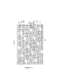
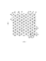
- the arrangement pattern of the sheet joint portion 40 of the expansion / contraction region 80 is not particularly limited, and any pattern (see, for example, Patent Documents 1 to 8) can be adopted, and in particular, the example shown in FIG. 9 and the example shown in FIG. 11 And, as in the example shown in FIG. 15, it is preferable that non-joining bands having continuous portions having no sheet joining portion exist in an oblique lattice pattern.
- the illustrated example shows a particularly preferable example, in which the stretchable region 80 has an acute angle (with respect to the stretchable direction ED) as non-joint bands 51 and 52 in which the portions having no sheet joint portion 40 are continuous in the expanded state.
- the first non-junction zone 51 that is linearly continuous along the first direction 51d intersecting the acute angle side crossing angle ⁇ 1) exists repeatedly at intervals in the direction orthogonal to the first direction 51d. Further, a large number of sheet joint portions 40 and joint holes 31 are provided at intervals between the adjacent first non-joining bands 51 in the expansion / contraction region 80. And characteristically, the unit structure including a plurality of first non-joining bands 51 having different first widths 51w, which are determined as widths in the direction orthogonal to the first direction 51d, is orthogonal to the first direction 51d in the expansion / contraction region 80. It exists repeatedly in the direction.
- the unit structure including the plurality of first non-joining bands 51 having different first widths 51w repeatedly exists in the direction orthogonal to the first direction 51d in the elastic region 80, the inside of the first non-joining band 51
- a similar width change of magnitude relation is formed in the continuous portion of the elastic sheet 30 of the above. That is, if the width 51w of the first non-joining band 51 is narrow, the width of the continuous portion of the internal elastic sheet 30 is also narrow, and if the width 51w of the first non-joining band 51 is wide, the continuous portion of the internal elastic sheet 30 is continuous. The width of the part also becomes wider.
- the expansion / contraction region 80 is stretched to some extent even in the natural length state (see FIGS. 13 and 17). Even when it is worn, it will have a beautiful appearance with diagonal stripes. That is, in a state of being contracted to some extent, the size of the contraction folds 25 in the first non-joining band 51 changes according to the first width 51w of the first non-joining band 51, and therefore, the diagonal stripes due to the influence of the contraction folds 25. The pattern will appear more clearly.
- the above-mentioned unit structure is not limited by the degree of the size of the width 51w as long as it includes a plurality of first non-joining bands 51 having different first widths 51w, but the first unit structure in the first non-joining band 51
- the width 51w is preferably 1.2 to 60 times larger and 0.01 to 0.8 times smaller than the first non-joint zone 51 having the nearest width 51w.
- the first width 51w in all the first non-joining bands 51 may be different and is shown.
- the first width 51w of some of the plurality of first non-joining bands 51 may be different from the first width 51w of the other single or plurality of first non-joining bands 51.
- the diagonal stripe pattern along the other diagonal direction appears in the same expansion / contraction region 80. If is more strongly visually recognized, the diagonal stripe pattern due to the continuous portion of the contraction folds 25 of the first non-joint band 51 may become inconspicuous.
- the maximum value of the first width 51w in the first non-joining zone 51 is the maximum value of the width in the direction orthogonal to the continuous direction in all the non-joining zones 51 and 52 having different and common inclination directions.
- the diagonal stripe pattern due to the contraction folds 25 of the first non-joining band 51 becomes more strongly visible in the expansion / contraction region 80, which is preferable.
- the maximum value of the first width 51w in the first non-joining band 51 can be appropriately determined, but it may be 1.2 to 60 times that of the first non-joining band 51 having the nearest width 51w. preferable.
- the width of all the non-joining bands 51 and 52 including the first non-joining band 51 is not limited in the direction orthogonal to the continuous direction, but is usually within the range of 0.02 to 5 mm. Is preferable. Needless to say, the width of the non-joining bands 51 and 52 in the direction orthogonal to the continuous direction is the first width 51w in the first non-joining band 51, which is a linearly continuous portion. Because it is the same width.
- the first spacing 51s which is determined as the spacing in the direction orthogonal to the first direction 51d in the adjacent first non-joining zones 51, can be appropriately determined. Therefore, the first interval 51s may be the same as the first width 51w in the adjacent first non-joining zone 51, may be wider, or may be narrower. As one preferable example, in the unit structure, the maximum value of the first width 51w in the first non-joining zone 51 may be smaller than the maximum value of the first interval 51s. By forming a wide interval portion in the unit structure in this way, the diagonal striped pattern due to the contraction folds 25 of the first non-joining band 51 becomes more strongly visible.
- the maximum value of the first width 51w in the first non-joining zone 51 can be appropriately determined, but it is preferably 0.01 to 9 times the maximum value of the first interval 51s.
- the distance between all the non-joining zones 51 and 52 including the first non-joining zone 51 in the direction orthogonal to the continuous direction is not particularly limited, but is usually within the range of 0.3 to 50 mm. Is preferable.
- the interval in the direction orthogonal to the continuous direction in the non-joining zones 51 and 52 is the first interval 51s in the first non-joining zone 51, which is equal to the continuous direction. ..
- the non-joint bands 51 and 52 are linearly continuous along the second direction 52d that intersects the acute angle (acute angle side intersection angle ⁇ 2) with respect to the extension / contraction direction ED other than the first direction 51d.
- the two non-joining bands 52 may repeatedly exist at intervals in the direction orthogonal to the second direction 52d, or the second non-joining band 52 may not exist.
- One preferable form having the second non-joining band 52 is that the non-joining bands 51 and 52 are formed in a diagonal lattice pattern in the expansion / contraction region 80, and the first non-joining band 51 is a diagonal lattice-like non-joining band.
- the second non-joining band 52 is a portion of the diagonal grid-like non-joining bands 51 and 52 that is continuous in the other direction.
- the positive and negative of the inclination with respect to the expansion / contraction direction ED are opposite to each other.
- the expansion / contraction region 80 is in the expanded state.
- the acute-angled crossing angles ⁇ 1 and ⁇ 2 with respect to the expansion / contraction direction ED in the first direction 51d and the second direction 52d are 5 to 45 degrees, particularly 10 to 30, so that sufficient elasticity in the expansion / contraction region 80 is ensured. Can be done.
- the diagonal stripe pattern due to the contraction folds 25 of the first non-joining band 51 may become inconspicuous. .. Therefore, when the second non-joining band 52 is provided as in the example shown in FIG. 15, the second width 52w determined as the width in the direction orthogonal to the second direction in the second non-joining band 52 is all the same or is the same. It is desirable to arrange the sheet joint portion 40 so as not to have the second non-joint band 52. As a result, the diagonal stripe pattern due to the contraction folds 25 of the first non-joining band 51 becomes more strongly visible in the expansion / contraction region 80.
- the sheet joints 40 are aligned in the first direction 51d between the adjacent first non-joint bands 51.
- all the sheet joints 40 are all aligned.
- the acute angle side crossing angle ⁇ 3 in the longitudinal direction with respect to the direction orthogonal to the expansion / contraction direction ED is within 10 degrees and the maximum dimension 40e of the expansion / contraction direction ED is 0.1 to 0.4 mm, the first non-joint is formed. It is preferable because the size of the expansion / contraction direction ED of the band 51 can be secured to be larger and the decrease in elasticity can be suppressed.
- the unit structure includes a wide first non-joining band 51 having a maximum first width 51w and a narrow first non-joining band 51 having a narrower first width 51w.
- the acute angle side intersection angle in the longitudinal direction with respect to the second direction 52d is within 5 degrees between the adjacent wide first non-joining bands 51.
- the sheet joints 40 having an elongated shape with a maximum dimension 40f in the direction orthogonal to the longitudinal direction of 0.1 to 0.4 mm are aligned in the first direction 51d at intervals.
- the acute angle side crossing angle ⁇ 3 in the longitudinal direction with respect to the first direction 51d is 45 degrees or more, and the maximum dimension 40 g in the direction orthogonal to the longitudinal direction is 0. It is preferable that the sheet joints 40 having an elongated shape of 1 to 0.4 mm are arranged at intervals in the first direction 51d. Due to the shape and arrangement of the sheet joints 40 in this way, the shrinkage folds 25 of the first non-joint band 51 are particularly visually emphasized with a smaller area of the sheet joints 40.
- the row of the sheet joints 40 (rows in the continuous direction of the non-joining bands 51 and 52) located between the adjacent non-joining bands 51 and 52 may be one row or a plurality of rows. Further, although the spacing between the sheet joints 40 in the row direction is preferably regular, not all spacings need to be constant, and some spacings may be different.
- a non-stretchable region 70 can be provided on at least one side of the stretchable region 80 in the width direction in the region of the exterior body 20 having the elastic sheet stretchable structure 20X.
- the non-stretchable region 70 means that the maximum stretch in the stretch direction is 120% or less.
- the maximum elongation of the non-stretchable region 70 is preferably 110% or less, and more preferably 100%.
- the arrangement of the stretchable region 80 and the non-stretchable region 70 can be appropriately determined.
- the non-stretchable region 70 is used as the non-stretchable region 70).
- the non-stretchable region 70 can be provided from the region that overlaps with the absorber 13 to the region that does not overlap with the absorber 13 located in the width direction WD or the front-rear direction LD, and the non-stretchable region is provided only in the region that does not overlap with the absorber 13. 70 can also be provided. Further, as shown in FIG. 7, it is not necessary to provide the non-stretchable region 70 in the region having the elastic sheet stretchable structure 20X.
- each sheet joint 40 in the non-stretchable region 70 is not particularly limited, and can be appropriately selected from the same shapes as those described in the section of the stretchable region 80.
- the area ratio of the sheet joint 40 and the area of each sheet joint 40 in the non-stretchable region can be appropriately determined, but in the normal case, the area of each sheet joint 40 is small if it is within the following range. Moreover, it is preferable that the non-stretchable region 70 does not become hard due to the low area ratio of the sheet joint portion 40.
- Area of sheet joint 40 0.10 to 0.75 mm 2 (particularly 0.10 to 0.35 mm 2 )
- Area ratio of sheet joint 40 4 to 13% (especially 5 to 10%)
- the non-stretchable region 70 can be formed by densely arranging the sheet joints 40 so that the first sheet layer 20A and the second sheet layer 20B do not shrink due to the contraction force of the elastic sheet 30 to form folds. it can.
- Specific examples of the method for forming the non-stretchable region 70 include those described in Patent Documents 3 to 6. 21 and 22 show an example of the non-stretchable region 70 described in Patent Document 6.
- the joint holes 31 are arranged in a staggered pattern in a dense arrangement to some extent, and the elastic sheet 30 is continuous with the expansion / contraction direction ED, but due to the presence of the joint holes 31, it is linear along the expansion / contraction direction ED. It does not have a continuous part.
- the ventilation holes 33 are opened with a size that is almost the same in both the natural length state and the unfolded state.
- the joining means of the first sheet layer 20A and the second sheet layer 20B in the sheet joining portion 40 is not particularly limited.
- the first sheet layer 20A and the second sheet layer 20B in the sheet joining portion 40 may be joined by a hot melt adhesive or by joining means by material welding such as heat sealing or ultrasonic sealing. ..
- the form in which the sheet joint 40 is formed by material welding is the first in the sheet joint 40.
- a first welded form in which the first sheet layer 20A and the second sheet layer 20B are joined only by a molten solidified product 20 m of at least one of the first sheet layer 20A and the second sheet layer 20B (FIG. 18 (a). )
- a second welded form in which the first sheet layer 20A and the second sheet layer 20B are joined only by the molten solidified product 30m of all or most or part of the elastic sheet 30 at the sheet joining portion 40 (FIG. 18 (FIG. 18). b)) or a third welding form in which both of these are combined (see FIG. 18C) may be used, but the second and third welding forms are preferable.
- the first sheet layer consisting of a part of the molten solidified product 20 m of the first sheet layer 20A and the second sheet layer 20B and the molten solidified product 30 m of all or most of the elastic sheet 30 at the sheet joint 40. It is a form in which 20A and the second sheet layer 20B are joined.
- the first sheet layer 20A and the second sheet layer 20A and the second sheet layer 20A and the second sheet layer 20A and the second sheet layer 20A and the second sheet layer 20A and the second sheet layer 20B use at least one of at least one of the 1st sheet layer 20A and the 2nd sheet layer 20B as an adhesive.
- the sheet layer 20B it is preferable that a part of the first sheet layer 20A and the second sheet layer 20B is not melted because the sheet bonding portion 40 is not hardened.
- the core (the core of all the fibers of the sheet joint 40 is required so that a part of the first sheet layer 20A and the second sheet layer 20B does not melt. Not only the core of the composite fiber but also the central part of the single component fiber remains), but the peripheral part (including not only the sheath of the composite fiber but also the surface layer side part of the single component fiber) is in a melted form or a part. The fibers do not melt at all, but the remaining fibers are all melted or the core remains but the surrounding part is melted.
- the peel strength becomes high.
- the first sheet layer 20A is under the condition that the melting point of at least one of the first sheet layer 20A and the second sheet layer 20B is higher than the melting point of the elastic sheet 30 and the heating temperature at the time of forming the sheet joint 40. It can be manufactured by sandwiching the elastic sheet 30 between the second sheet layer 20B, pressurizing and heating the portion to be the sheet joint 40, and melting only the elastic sheet 30.
- the melting point of at least one of the first sheet layer 20A and the second sheet layer 20B is higher than the melting point of the elastic sheet 30, between the first sheet layer 20A and the second sheet layer 20B. It can be manufactured by sandwiching the elastic sheet 30 and pressurizing and heating the portion to be the sheet joint portion 40 to melt at least one of the first sheet layer 20A and the second sheet layer 20B and the elastic sheet 30.
- the melting point of the elastic sheet 30 is preferably about 80 to 145 ° C., and the melting points of the first sheet layer 20A and the second sheet layer 20B are about 85 to 190 ° C., particularly about 150 to 190 ° C.
- the difference between the melting points of the first sheet layer 20A and the second sheet layer 20B and the melting points of the elastic sheet 30 is preferably about 60 to 90 ° C.
- the heating temperature is preferably about 100 to 150 ° C.
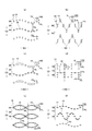
- the molten solidified product 30 m of the elastic sheet 30 is a sheet joint portion as shown in FIG. 19 (c).
- the first sheet layer 20A and the second sheet layer 20B in No. 40 may permeate between the fibers over the entire thickness direction, but as shown in FIG. 19A, they permeate between the fibers to the middle in the thickness direction, or As shown in FIG. 19B, the sheet joint 40 has higher flexibility in a form in which the fibers of the first sheet layer 20A and the second sheet layer 20B hardly permeate between the fibers.
- FIG. 20 shows an example of an ultrasonic sealing device suitable for forming the second welding form and the third welding form.
- this ultrasonic sealing device when forming the sheet joint 40, the first sheet layer 20A, between the anvil roll 100 having the protrusion 100a formed in the pattern of the sheet joint 40 on the outer surface and the ultrasonic horn 101, The elastic sheet 30 and the second sheet layer 20B are fed.
- the feed drive roll 103 and the nip roll 102 are made slower than the transfer speed of the anvil roll 100 and the ultrasonic horn 101 or later, the feed drive roll 103 and the nip roll 102
- the elastic sheet 30 is extended to a predetermined elongation rate in the MD direction (machine direction, flow direction) by the path from the nip position by the anvil roll 100 to the seal position by the ultrasonic horn 101.
- the elongation rate of the elastic sheet 30 can be set by selecting the speed difference between the anvil roll 100 and the feed drive roll 103, and can be set to, for example, about 300% to 500%.
- 102 is a nip roll.
- the first sheet layer 20A, the elastic sheet 30, and the second sheet layer 20B fed between the anvil roll 100 and the ultrasonic horn 101 are laminated in this order, and the protrusion 100a and the ultrasonic horn 101 are combined. While pressurizing between, it is heated by the ultrasonic vibration energy of the ultrasonic horn 101 to melt only the elastic sheet 30, or at least one of the first sheet layer 20A and the second sheet layer 20B and the elastic sheet 30 are melted.
- the area ratio of the sheet joint 40 is selected by selecting the size, shape, separation interval, arrangement pattern in the roll length direction and roll circumferential direction of the protrusion 100a of the anvil roll 100, and the like. Can be done.
- the joint hole 31 is formed from the portions on both sides in the expansion / contraction direction by the joint holes 31 as shown in FIGS. 9A, 12 and 13. Since it will be cut and lose the support on both sides in the contraction direction, it contracts until the center side of the LD in the direction orthogonal to the expansion / contraction direction ED is balanced with the center side in the expansion / contraction direction within the range where continuity in the direction orthogonal to the contraction direction can be maintained. Then, the joint hole 31 expands in the expansion / contraction direction ED.
- the constituent materials of the first sheet layer 20A and the second sheet layer 20B can be used without particular limitation, but are preferably breathable. Therefore, it is preferable to use a non-woven fabric from these viewpoints and from the viewpoint of flexibility.
- the basis weight is preferably about 10 to 25 g / m 2.
- a part or all of the first sheet layer 20A and the second sheet layer 20B may be a pair of layers in which one material is folded back and opposed to each other.
- the constituent material located on the outside is the second sheet layer 20B, and the folded portion 20C formed by folding back toward the inner surface side at the waist opening edge is used as the first sheet layer 20A.
- the elastic sheet 30 is interposed between them, and the constituent material located inside is the first sheet layer 20A and the constituent material located outside is the second sheet layer 20B in the other parts, and the elastic sheet 30 is placed between them. Can be intervened.
- the constituent material of the first sheet layer 20A and the constituent material of the second sheet layer 20B are individually provided over the entire front-rear direction LD, and the constituent material of the first sheet layer 20A and the second sheet are not folded back.
- An elastic sheet 30 can also be interposed between the constituent members of the layer 20B.
- the elastic sheet 30 is not particularly limited, and may be an elastic non-woven fabric as long as it is a sheet made of a thermoplastic resin having elasticity by itself. Further, as the elastic sheet 30, in addition to a non-perforated sheet, a sheet having a large number of holes and slits formed for ventilation can also be used.
- the tensile strength in the width direction WD (extension direction ED, MD direction) is 8 to 25 N / 35 mm
- the tensile strength in the front-rear direction LD (direction XD, CD direction orthogonal to the expansion / contraction direction) is 5 to 20 N / 35 mm, and the width direction.
- the elastic sheet 30 has a tensile elongation of 450 to 1050% in the WD and a tensile elongation of 450 to 1400% in the front-rear LD.
- the thickness of the elastic sheet 30 is not particularly limited, but is preferably about 20 to 40 ⁇ m.
- the ventilation hole 33 is a portion where the edge of the joint hole 31 is formed apart from the outer peripheral edge of the sheet joint portion 40 in the expansion / contraction direction ED, the ventilation hole 33 is deformed by the extension of the elastic sheet 30 and is in the expanded state. The closer it gets, the bigger it gets. Further, depending on the shape (for example, circular shape) of the sheet joint 40, the edge of the joint hole 31 and the outer peripheral edge of the sheet joint 40 may be in close contact with each other in a natural length state, and the ventilation hole 33 may not be formed.
- the joint holes 31 are stretched in the expansion / contraction direction ED, so that ventilation holes 33 are opened at least on both sides of the expansion / contraction direction ED of the sheet joint portion 40. Since the ventilation holes 33 improve the air permeability, as highlighted in FIGS. 12 and 13, FIG. 16 and FIG. 17, being visually recognized by the user gives the product a functional aesthetic appearance. Although it will bring about it, it may be perceived as an unfavorable appearance by some users.
- the color difference ⁇ E between the color of the outer surface of the elastic sheet 30 and the color of the outer surface of the first sheet layer 20A (lower sheet layer) is set to 5 or less, and the color of the outer surface of the elastic sheet 30 and the outer surface of the first sheet layer 20A are passed through. Since the difference from the color of the portion viewed from the pore 33 is small, it is preferable to make the shape of the ventilation hole 33 difficult to see through the second sheet layer 20B (outer sheet layer).
- the color difference ⁇ E between the color of the outer surface 30s of the elastic sheet 30 and the color of the outer surface 20s of the first sheet layer 20A is more preferably 3 or less, and particularly preferably 1.5 or less.
- the region where the color difference ⁇ E between the color of the outer surface 30s of the elastic sheet 30 and the color of the outer surface 20s of the first sheet layer 20A is 5 or less is the entire region having the elastic sheet elastic structure 20X. However, it may be a part of the region, for example, only the exposed portion exposed on the outer surface. However, it is desirable that the aesthetic improvement region is a region including the entire one or a plurality of ventilation holes 33 (preferably the joint holes 31).
- the aesthetic improvement region can be provided in only one of the stretchable region 80 and the non-stretchable region 70, or can be provided in both.
- the aesthetic improvement areas may be provided at a plurality of places at intervals, or the aesthetic improvement areas having different color differences may be provided at a plurality of places at intervals or adjacent to each other.
- the stretchable region 80 and the non-stretchable region may be provided with different color difference aesthetic improvement regions, or the waist end 23 region and other regions may be provided with different color difference aesthetic improvement regions.
- the shape of the elastic sheet 30 is within the above-mentioned color difference range, the elastic sheet 30 has a low light transmittance, for example, 40. Even if it is ⁇ 60%, the shape of the ventilation hole 33 can be obscured.
- the light transmittance of the first sheet layer 20A is preferably 0.5 to 2.0 times, particularly 0.8 to 1.6 times, the light transmittance of the elastic sheet 30.
- the second sheet layer 20B (outer sheet layer) is preferably made of a material having a low light transmittance, for example, a non-woven fabric having a high basis weight.
- a non-woven fabric having a high basis weight.
- the outer surface of the product may be hard to the touch and the air permeability may be lowered.
- the second sheet layer 20B is a flexible and highly breathable non-woven fabric having a fineness of 1.0 to 6.0 dtex and a basis weight of 15 to 25 g / m 2 (if the light transmittance is 50% or more, particularly 65 to 80%), and if the shape of the ventilation hole 33 is made difficult to see due to the color difference described above, the performance balance will be good.
- the stretchable region 80 of the example shown in FIGS. 11 to 13 and 15 to 17 and the non-stretchable region 70 of the example shown in FIGS. 21 and 22 As described above, it is preferable that the ventilation holes 33 are opened in a state of natural length. However, since this type of product is sold in a natural length state, having an opening in the elastic sheet 30 in the natural length state may affect the appearance of the product before use. Therefore, each of the above-described aspects becomes particularly significant when applied to a structure in which the ventilation holes 33 are opened in a state of natural length.
- the elastic sheet 30, the first for various purposes such as adjusting the color difference ⁇ E and the light transmittance of the color of the outer surface 30s of the elastic sheet 30 and the color of the outer surface 20s of the first sheet layer 20A, or coloring the product.
- At least one surface of the sheet layer 20A and the second sheet layer 20B can be colored.
- the coloring method is not particularly limited, but when a single material is colored in multiple colors, it can be performed by printing or post-dyeing, and when the entire material is colored in a single color, printing or post-dyeing is adopted.
- a method of mixing a dye or a pigment with a raw material so-called dyeing.
- a non-woven fabric a non-woven fabric is formed by a stock-colored fiber colored by mixing a dye or a pigment with a stock solution before spinning). You can also.
- coloring When such coloring is performed, it may be colored only in the aesthetic improvement area, or may be colored in a wider area including the aesthetic improvement area, for example, the entire material. Further, when a plurality of aesthetic areas are provided, different colors may be used for each aesthetic area.
- the elastic sheet 30, the first sheet layer 20A, and the second sheet layer 20B may be uncolored (that is, the raw material color remains) as long as the above color difference is satisfied.
- the elastic sheet 30, the first sheet layer 20A, and the second sheet layer 20B are each made of a sheet having an outer surface of 60 to 80% whiteness. Is preferable.
- the whiteness of the outer portion of the hole is low, the difference between the outer portion of the hole and the shadow generated at the edge of the hole is reduced, and the elastic sheet 30 has a white appearance preferred by hygiene products.
- the holes in the above and the holes in the perforated non-woven fabric, which will be described later, are less noticeable.
- the whiteness of a material can be adjusted by the content of a white pigment such as titanium oxide.
- the second sheet layer 20B uniformly covers the outside of the elastic sheet 30, even if the color difference with respect to the elastic sheet 30 is large, it does not directly affect the appearance of the ventilation holes 33, but when different colors are laminated, it does not directly affect the appearance. Since it is difficult to obtain a desired color, it is preferable that the color difference ⁇ E between the color of the outer surface of the elastic sheet 30 and the color of the outer surface of the second sheet layer 20B is 5 or less.
- the holes of the perforated non-woven fabric are conspicuous, and some users may feel that the appearance is not so preferable. is there.
- the color difference ⁇ E between the color of the outer surface of the elastic sheet 30 and the color of the outer surface of the second sheet layer 20B is 5 or less, more preferably 3 or less, and particularly preferably 1.5 or less, the elastic sheet 30 Since the difference between the color of the outer surface and the color of the outer surface of the second sheet layer 20B is small, the shape of the holes in the second sheet layer 20B becomes less noticeable.
- the second sheet layer 20B is made of a perforated non-woven fabric to improve the air permeability and to be aesthetically pleasing.
- a perforated non-woven fabric can be used for the first sheet layer 20A (lower sheet layer), it is desirable to use a non-perforated non-woven fabric.
- the perforated nonwoven fabric used for the second sheet layer 20B is not particularly limited, and holes may be uniformly formed throughout the second sheet layer 20B, or a region having no holes in a part thereof may be formed. You may have.
- the planar shape (opening shape) of each hole can be determined as appropriate.
- the hole 14 has an elongated hole shape as shown in FIGS. 23 (b) and 24 (b), and has a perfect circular shape as shown in FIGS. 23 (e) (f) and 24 (e). It can be any shape such as an ellipse, a triangle, a rectangle, a polygon such as a rhombus, a star shape, a cloud shape, etc. as shown in a) (d) and FIGS. 24 (a), (d), and (f). As shown in FIGS. 23 (c) and 24 (c), holes 14 having different shapes may be mixed.
- the dimensions of the individual holes 14 are not particularly limited, but the dimensions in the CD direction (dimensions of the longest portion) 14L are preferably 0.6 to 5.0 mm, particularly 0.7 to 2.0 mm, and are preferably 0.7 to 2.0 mm in the MD direction.
- the dimension (dimension of the longest portion) 14W is preferably 0.6 to 5.0 mm, particularly preferably 0.6 to 1.2 mm.
- shape of the hole 14 is a shape that is long in one direction (a shape in which the total length in one direction is longer than the total length in the direction orthogonal to this) such as an elongated hole shape, an elliptical shape, a rectangle, a diamond shape, etc., the dimension in the MD direction.
- the (dimension of the longest portion) is preferably 1.2 to 2.5 times the dimension in the CD direction (dimension of the longest portion) orthogonal to this.
- the longitudinal direction of the hole 14 is preferably the MD direction of the non-woven fabric, but it may be the CD direction or an oblique direction inclined with respect to these.
- the MD direction of the non-woven fabric is the width direction WD in the outer body 20 of the pants-type disposable diaper, and the inner body 200 of the pants-type disposable diaper, the part other than the fastening tape in the tape-type disposable diaper, and the pad-type disposable diaper.
- the LD is in the anterior-posterior direction.
- each hole 14 may be appropriately determined, but the area is preferably about 0.1 to 2.7 mm 2 (particularly 0.1 to 1.0 mm 2 ), and the area ratio is 1. It is preferably about 0 to 15.0% (particularly 5.0 to 10.0%).
- the plane arrangement of the holes 14 can be appropriately determined and may be irregular, or may be a pattern, a character shape, or the like, but a plane arrangement that is regularly repeated is preferable.
- rows of holes 14 linearly arranged at predetermined intervals in the CD direction have predetermined intervals in the MD direction. It is preferable that the matrix is vacant and repeated.
- the spacing 14x in the MD direction of the holes 14 is shorter than the spacing 14y in the CD direction of the holes 14, and as shown in FIG. 23 (c), the holes 14 are arranged.
- the MD-direction spacing 14x and the CD-direction spacing 14y of the holes 14 are approximately equal, or as shown in FIG. 23 (d), the MD-direction spacing 14x of the holes 14 is greater than the CD-direction spacing 14y of the holes 14.
- the rows of holes 91 and 92 linearly arranged at predetermined intervals in the CD direction are spaced apart in the MD direction and displaced in the CD direction. It can be arranged side by side.
- the example shown in FIG. 23B is a so-called staggered (hexagonal lattice) arrangement in which the arrangement of the holes 14 is staggered in the adjacent hole rows 91 and 92.
- the holes 14 are arranged in a wavy line having a center line along the orthogonal direction.
- a row of holes 14 arranged at intervals in the direction orthogonal to the MD direction is included in those arranged at intervals in the MD direction.
- the size and shape of the hole 14 in the first hole row 91 and the size and shape of the hole 14 in the second hole row 92 may be the same, but it is more preferable that at least one of them is different.
- the CD direction spacing 14y and the MD direction spacing 14x of the holes 14 may be constant or variable, respectively. These can be appropriately determined, but in consideration of air permeability, it is desirable that the CD direction spacing 14y of each of the holes 14 is within the range of 0.9 to 8.0 mm, particularly 1.0 to 3.0 mm, and the holes are preferably set. It is desirable that the MD direction spacing 14x is within the range of 2.0 to 10 mm, particularly 3.0 to 5.0 mm. In particular, rows of holes 14 lined up in the CD direction with a CD direction spacing 14y narrower than the CD direction dimension 14L of the holes 14 are repeated at predetermined intervals in the MD direction, and the MD direction spacing 14x is larger than the CD direction dimension 14L of the holes 14.
- the hole 14 has a dimension of 14 W in the MD direction or more), the improvement in air permeability is remarkable, the softness and bulkiness are not impaired, and the MD direction is important during manufacturing. It is preferable because the decrease in tensile strength of the material is smaller. In particular, in this case, it is preferable that the shape of the hole 14 is elongated in the CD direction.
- the group 90 of the holes 14 arranged in a single wavy shape following the MD direction are spaced apart in the CD direction.
- the group 90 of holes 14 arranged at intervals so as to form a chain extending in the MD direction can be arranged at intervals in the CD direction.
- the group 90 of the holes 14 arranged in a chain shape is not particularly limited as long as the portions of the holes 14 arranged in an annular shape are repeated at intervals in the MD direction.
- the peaks are opposite to each other.
- the group 90 of the holes 14 arranged in a heavy wavy shape can be arranged at intervals in the CD direction, or can be formed in a chain shape as shown in FIG. 25.
- the group 90 of the holes 14 are lined up at intervals in the CD direction means that a non-perforated portion 93 that is straight and continuous along the MD direction is provided between the groups 90 of the holes 14 adjacent to each other in the CD direction. Means to have.
- the arrangement shape in the group 90 of the holes 14 can be appropriately determined as long as it is wavy, and the peaks and valleys of the arc curve as shown in FIG. 24 (a) are repeatedly wavy, or as shown in FIG. 24 (b).
- regular shapes such as a triangular wave shape, a rectangular wave shape as shown in FIG. 24 (d), and a sinusoidal curve shape as shown in group 90 of the holes 14 in the middle of FIG. At least one of them may have a shape that changes regularly or irregularly, or the other may have an irregular shape.
- the distance 14x of the holes 14 in the MD direction in the group 90 of the holes 14 may be constant or may be changed, and can be appropriately determined. Considering the improvement of air permeability by the holes 14, it is desirable that the diameter is in the range of 2.0 to 10 mm, particularly 3.0 to 5.0 mm.
- the distance 14y of the holes 14 in the row 94 of each hole 14 in the CD direction may be changed, and the example shown in FIGS. 24 (a) and 24 (b) may be changed. It may be constant as such.
- the distance 14y of the holes 14 in the row 94 of the holes 14 in the CD direction is preferably in the range of 0.9 to 8.0 mm, particularly 1.0 to 3.0 mm.
- the distance 14y of the holes 14 in the row 94 of the holes 14 in the CD direction may be longer than or about the same as the distance 14x of the holes 14 in the MD direction in the group 90 of the holes 14, but is shorter (2 to 2 to). It is desirable (about 5 times).
- the cross-sectional shape of the hole 14 is not particularly limited.
- the hole 14 is a punched type hole whose peripheral edge is formed by a cut end of a fiber, there is almost no cut end of the fiber on the peripheral edge of the hole 14, and a pin is inserted between the fibers and expanded. It may be a non-punched type hole (high fiber density at the edge) formed in the above.
- the punched-type hole has a diameter of the hole 14 that becomes smaller toward the middle in the thickness direction, but is not shown, but becomes smaller toward one side in the thickness direction. You may.
- the non-punched type hole 14 becomes smaller as the diameter of the hole 14 increases from the pin insertion side to the opposite side. This includes those in which the diameter of the holes 14 continues to decrease over the entire thickness direction of the non-woven fabric layer, and those in which the decrease in the diameter of the holes 14 almost disappears in the middle of the thickness direction.
- fibers are extruded from the edge of the hole 14 on the side opposite to the pin insertion side to the side opposite to the pin insertion side.
- a portion (burr) 14e is formed and a protruding portion 14e is not formed on the pin insertion side, and as shown in FIG.
- fibers are pin-inserted at the edge of the hole 14 on the side opposite to the pin insertion side.
- a projecting portion 14e extruded to the side opposite to the side is formed, and a projecting portion 14e formed by extruding fibers to the pin insertion side is formed on the pin insertion side.
- the protrusion height 14h of the protrusion 14e is substantially uniform as shown in FIG. 26A, and the protrusion 14e is formed as shown in FIG. 26C.
- a facing portion having the highest protruding height 14i and a facing portion facing in a direction orthogonal to the facing portion having the lowest protruding height 14j are included.
- the protruding portion 14e has a continuous tubular shape in the circumferential direction of the hole, but the protruding portion 14e of a part or all of the hole 14 is formed only in a part of the circumferential direction of the hole 14. May be good.
- the protrusion heights 14h, 14i, 14j (apparent heights measured using an optical microscope without applying pressure) are preferably about 0.2 to 1.2 mm.
- the highest protruding height 14i in the protruding portion 14e is preferably about 1.1 to 1.4 times the lowest protruding height 14j.
- the protruding height of the protruding portion 14e may change in the circumferential direction of the hole 14.
- a protruding portion (burr) 14e is formed in which the protruding height 14i of the facing portion in the longitudinal direction of the hole 14 is higher than the protruding height 14j of the facing portion in the direction orthogonal to the longitudinal direction.
- the protruding portion 14e of the hole 14 may have a lower fiber density than the surrounding portion, but preferably has the same or higher fiber density.
- the disposable wearable article may have a display sheet 16 having a character or the like displayed in at least one of the front body F and the back body B. ..
- a display sheet 16 is preferably built in the exterior body 20 when only the visibility of the display 27 is considered.
- the exterior body 20 is an elastic member having an elastic sheet 30 built-in as in this example, incorporating the display sheet 16 between the first sheet layer 20A and the second sheet layer 20B means that the display sheet 16 is built in the first sheet layer. It is not preferable because the display sheet 16 may hinder the bonding between the 20A and the second sheet layer 20B.
- the display sheet 16 is interposed between the exterior body 20 and the interior body 10 so that the display of the display sheet 16 can be seen through the exterior body 20.
- the display of the display sheet 16 since the display of the display sheet 16 is viewed through the elastic sheet 30, if the ventilation holes 33 are conspicuous, the display of the display sheet 16 may be difficult to see or the design of the display may be impaired. If the above-mentioned color difference or the like is devised, the display sheet 16 can be easily seen even if the display sheet 16 is interposed between the exterior body 20 and the interior body 10.
- a resin film is used because it is suitable for high-definition printing.
- a highly opaque resin film it is necessary to provide a printing portion on the outer surface of the display sheet 16.
- a printing portion is provided on the inner surface of the display sheet 16. You can also do it.
- the display added to the display sheet 16 is not particularly limited, and is a functional display such as a pattern for decoration (including a picture or a one-point character), usage method, usage assistance, size, etc., or a manufacturer, product name, or characteristic.
- a display such as a mark display such as a function can be added by printing or the like.
- At least one of the inner surface and the outer surface of the display sheet 16 is adhered to the facing surface via a hot melt adhesive.
- the dimensions of the display sheet 16 may be appropriately determined, but in a normal case, the display sheet 16 is preferably provided within the range of the width direction WD overlapping the interior body 10 and equal to or less than the width of the interior body 10. Specifically, it is preferable that the width is 50 to 100% of the width of the interior body 10 because it can be easily attached to the interior body 10 side at the time of manufacturing.
- the display sheet 16 does not have to be provided.
- Front body and rear body mean the front and rear parts of the pants-type disposable wear item with the center in the front-rear direction as the boundary, respectively.
- the crotch portion means a front-rear direction range including the center in the front-rear direction of the disposable worn article, and when the absorber has a constricted portion, it means a front-rear direction range of the portion having the constricted portion.
- the "front-back direction” means the direction indicated by the symbol LD in the figure (vertical direction), and the “width direction” means the direction indicated by the WD in the figure (horizontal direction), and the front-back direction and the width direction. Are orthogonal.
- the "MD direction” and "CD direction” mean the flow direction (Machine Direction) in the manufacturing equipment and the lateral direction (Cross Direction) orthogonal to this, and one of them is the front-rear direction depending on the part of the product. And the other is in the width direction.
- the MD direction of the non-woven fabric is the direction of fiber orientation of the non-woven fabric.
- the fiber orientation is the direction along which the fibers of the non-woven fabric follow.
- the measurement method according to the fiber orientation test method based on the zero-distance tensile strength of the TAPPI standard method T481 or the fibers based on the tensile strength ratio in the anteroposterior direction and the width direction It can be discriminated by a simple measuring method for determining the orientation direction.
- Maximum elongation means the maximum value of elongation in the expansion / contraction direction ED (in other words, elongation in the expanded state in which the first sheet layer and the second sheet layer are expanded flat without shrinkage or slack), and is in the expanded state.
- the length is expressed as a percentage when the natural length is 100%.
- Area ratio means the ratio of the target portion to the unit area, and the target portion (for example, the sheet joint portion 40, the opening of the joint hole 31, the ventilation hole) in the target region (for example, the stretchable region 80 and the non-stretchable region 70). ) Is divided by the area of the target area and expressed as a percentage.
- the "area ratio" in the region having a stretchable structure means the area ratio in the expanded state. In a form in which a large number of target portions are provided at intervals, it is desirable to set the target area to a size that includes 10 or more target portions and obtain the area ratio.
- Elongation rate means the value when the natural length is 100%. For example, an elongation rate of 200% is synonymous with an elongation ratio of 2 times.
- Methodsuke is measured as follows. After pre-drying the sample or test piece, leave it in a test room or device under standard conditions (test location: temperature 23 ⁇ 1 ° C., relative humidity 50 ⁇ 2%) to bring it to a constant weight. Pre-drying refers to making a sample or test piece constant in an environment at a temperature of 100 ° C. It is not necessary to pre-dry the fibers having an official moisture content of 0.0%. A sample having a size of 100 mm ⁇ 100 mm is cut out from the test piece in a constant weight state using a sampling template (100 mm ⁇ 100 mm). The weight of the sample is measured and multiplied by 100 to calculate the weight per square meter, which is used as the basis weight.
- the "thickness" of the absorber is the thickness measuring instrument of Ozaki Seisakusho Co., Ltd. (peacock, dial thickness gauge large type, model JB (measurement range 0 to 35 mm) or model K-4 (measurement range 0 to 50 mm)) Measure with the sample and the thickness measuring device horizontal.
- the "thickness" other than the above is automatically measured using an automatic thickness measuring device (KES-G5 handy compression measurement program) under the conditions of a load of 0.098 N / cm 2 and a pressurized area of 2 cm 2.
- KS-G5 handy compression measurement program automatic thickness measuring device
- test piece has a rectangular shape with a width of 35 mm and a length of 80 mm. It means a value measured with an initial chuck interval (distance between marked lines) of 50 mm and a tensile speed of 300 mm / min.
- initial chuck interval distance between marked lines
- tensile speed 300 mm / min.
- AUTOGRAPH AGS-G100N manufactured by SHIMADZU can be used as the tensile tester.
- Elongation stress is defined by a tensile test in which the initial chuck interval (distance between marked lines) is 50 mm and the tensile speed is 300 mm / min according to JIS K7127: 1999 "Plastic-Test method for tensile properties”. , Means the tensile stress (N / 35 mm) measured when stretching in the elastic region, and the degree of stretching can be appropriately determined depending on the test object.
- the test piece is preferably rectangular with a width of 35 mm and a length of 80 mm or more. However, if a test piece having a width of 35 mm cannot be cut out, a test piece is prepared with a width that can be cut out, and the measured value is measured with a width of 35 mm.
- the L * value, a * value and b * value of "CIELAB” shall be measured as follows according to JIS Z 8781-4 "Part 4: CIE 1976 L * a * b * color space”.
- the first sheet layer (lower sheet layer) and the elastic sheet are taken out in their respective states and used as a sample. Then, for example, using a measuring device such as X-Rite eXact Standard (measurement diameter: 1.5 mm) manufactured by X-Rite, the sample is placed with a white reflection standard (white plate) on the inner surface of the sample in the unfolded state.
- the outer surface of the portion without the sheet joint, and in the elastic sheet, the outer surface of the portion without the joint hole are arbitrarily determined at three points, and the L * value of each point is determined.
- the a * value and the b * value are measured, and the average value is used as the measured value. It should be noted that the measurement diameter of the measuring device is large with respect to the sheet joint portion and the joint interval, and it is not possible to measure only the portion of the first sheet layer (lower sheet layer) where there is no sheet joint portion, or there is no joint hole in the elastic sheet.
- a sample can be prepared using the same material as the product, and the L * value, a * value and b * value can be measured.
- a large number of parts of the first sheet layer (lower sheet layer) having no sheet joints and only parts of the elastic sheet without joint holes are cut out, and gaps or overlaps on the white reflection standard (white plate), resulting in shadows.
- the L * value, the a * value, and the b * value may be measured by pasting them side by side so that
- ⁇ E (( ⁇ L *) 2 + ( ⁇ a *) 2 + ( ⁇ b *) 2 ) 1/2
- Translucency means the translucency specified in the translucency (JIS method) specified in JIS L 1913: 2010.
- ⁇ "Whiteness” means ISO 2470: 1999 Paper, border and pulps-Measurement of difference blue reflectance factor (ISO brightness) (MOD).
- ISO brightness difference blue reflectance factor
- MOD difference blue reflectance factor
- the sample size is specified in the same regulation, there is no limitation on the sample size as long as it can be measured by the measuring device.
- the number of laminated samples is 10.
- the whiteness measuring device for example, a light communication Hiroshi YQ-Z-48B, a simple spectroscopic color difference meter NF333 manufactured by Nippon Denshoku Kogyo Co., Ltd., and a spectroscopic white meter PF-10 can be used.
- Unfolded state means a state in which it is unfolded flat without shrinkage or slack.
- the dimensions of each part mean the dimensions in the unfolded state, not in the natural length state.
- test or measurement shall be performed in a test room or equipment under standard conditions (test location: temperature 23 ⁇ 1 ° C, relative humidity 50 ⁇ 2%). To do.
- the present invention includes pants-type disposable diapers as in the above example, various disposable diapers such as tape type and pad type, sanitary napkins, swimming, etc., as long as they have an elastic area to which the elastic sheet elastic structure can be applied. It can be used as an elastic member for all disposable wear items such as disposable wear items for playing in water.
Landscapes
- Health & Medical Sciences (AREA)
- Epidemiology (AREA)
- Engineering & Computer Science (AREA)
- Biomedical Technology (AREA)
- Heart & Thoracic Surgery (AREA)
- Vascular Medicine (AREA)
- Life Sciences & Earth Sciences (AREA)
- Animal Behavior & Ethology (AREA)
- General Health & Medical Sciences (AREA)
- Public Health (AREA)
- Veterinary Medicine (AREA)
- Dermatology (AREA)
- Absorbent Articles And Supports Therefor (AREA)
Priority Applications (3)
| Application Number | Priority Date | Filing Date | Title |
|---|---|---|---|
| JP2021554047A JP7299332B2 (ja) | 2019-11-01 | 2019-11-20 | 伸縮部材及びこの伸縮部材を有する使い捨て着用物品 |
| EP19951176.7A EP4032517A4 (en) | 2019-11-01 | 2019-11-20 | STRETCHY ELEMENT AND DISPOSABLE WEARABLE ARTICLE COMPRISING SUCH STRETCHABLE ELEMENT |
| KR1020227011093A KR102669403B1 (ko) | 2019-11-01 | 2019-11-20 | 신축 부재 및 이 신축 부재를 갖는 일회용 착용 물품 |
Applications Claiming Priority (2)
| Application Number | Priority Date | Filing Date | Title |
|---|---|---|---|
| CN201911059379.2 | 2019-11-01 | ||
| CN201911059379.2A CN112754775B (zh) | 2019-11-01 | 2019-11-01 | 伸缩部件和具有该伸缩部件的一次性穿着物品 |
Publications (1)
| Publication Number | Publication Date |
|---|---|
| WO2021084764A1 true WO2021084764A1 (ja) | 2021-05-06 |
Family
ID=75692016
Family Applications (1)
| Application Number | Title | Priority Date | Filing Date |
|---|---|---|---|
| PCT/JP2019/045424 Ceased WO2021084764A1 (ja) | 2019-11-01 | 2019-11-20 | 伸縮部材及びこの伸縮部材を有する使い捨て着用物品 |
Country Status (5)
| Country | Link |
|---|---|
| EP (1) | EP4032517A4 (https=) |
| JP (1) | JP7299332B2 (https=) |
| KR (1) | KR102669403B1 (https=) |
| CN (1) | CN112754775B (https=) |
| WO (1) | WO2021084764A1 (https=) |
Cited By (1)
| Publication number | Priority date | Publication date | Assignee | Title |
|---|---|---|---|---|
| JP2022173945A (ja) * | 2021-05-10 | 2022-11-22 | ユニ・チャーム株式会社 | ショーツ型ナプキン、及び、ショーツ型ナプキン群 |
Citations (11)
| Publication number | Priority date | Publication date | Assignee | Title |
|---|---|---|---|---|
| JP2015204982A (ja) | 2014-04-18 | 2015-11-19 | 日本製紙クレシア株式会社 | パンツ型吸収性物品 |
| JP2016140477A (ja) | 2015-01-30 | 2016-08-08 | 大王製紙株式会社 | 吸収性物品の伸縮構造、及びこれを用いたパンツタイプ使い捨ておむつ |
| JP2016189933A (ja) | 2015-03-31 | 2016-11-10 | 大王製紙株式会社 | 吸収性物品の製造方法 |
| JP2016189932A (ja) | 2015-03-31 | 2016-11-10 | 大王製紙株式会社 | 吸収性物品 |
| JP2016189931A (ja) | 2015-03-31 | 2016-11-10 | 大王製紙株式会社 | 吸収性物品及びその製造方法 |
| JP2017064224A (ja) | 2015-09-30 | 2017-04-06 | 大王製紙株式会社 | 吸収性物品 |
| JP2017064225A (ja) * | 2015-09-30 | 2017-04-06 | 大王製紙株式会社 | 吸収性物品 |
| JP2017148169A (ja) | 2016-02-23 | 2017-08-31 | 大王製紙株式会社 | 吸収性物品及びその製造方法 |
| JP2017225508A (ja) | 2016-06-20 | 2017-12-28 | 大王製紙株式会社 | 使い捨て着用物品 |
| JP2018051230A (ja) * | 2016-09-30 | 2018-04-05 | 大王製紙株式会社 | 使い捨て着用物品及びその製造方法 |
| JP2018164669A (ja) * | 2017-03-28 | 2018-10-25 | 株式会社リブドゥコーポレーション | 使い捨てパンツ型おむつ |
Family Cites Families (3)
| Publication number | Priority date | Publication date | Assignee | Title |
|---|---|---|---|---|
| JP4845383B2 (ja) * | 2005-01-19 | 2011-12-28 | ユニ・チャーム株式会社 | 使い捨て着用物品 |
| JP5886576B2 (ja) * | 2011-09-16 | 2016-03-16 | ユニ・チャーム株式会社 | 止着部材及び止着片 |
| JP6049222B2 (ja) * | 2015-03-30 | 2016-12-21 | 大王製紙株式会社 | 吸収性物品及びその製造方法 |
-
2019
- 2019-11-01 CN CN201911059379.2A patent/CN112754775B/zh active Active
- 2019-11-20 EP EP19951176.7A patent/EP4032517A4/en active Pending
- 2019-11-20 JP JP2021554047A patent/JP7299332B2/ja active Active
- 2019-11-20 WO PCT/JP2019/045424 patent/WO2021084764A1/ja not_active Ceased
- 2019-11-20 KR KR1020227011093A patent/KR102669403B1/ko active Active
Patent Citations (11)
| Publication number | Priority date | Publication date | Assignee | Title |
|---|---|---|---|---|
| JP2015204982A (ja) | 2014-04-18 | 2015-11-19 | 日本製紙クレシア株式会社 | パンツ型吸収性物品 |
| JP2016140477A (ja) | 2015-01-30 | 2016-08-08 | 大王製紙株式会社 | 吸収性物品の伸縮構造、及びこれを用いたパンツタイプ使い捨ておむつ |
| JP2016189933A (ja) | 2015-03-31 | 2016-11-10 | 大王製紙株式会社 | 吸収性物品の製造方法 |
| JP2016189932A (ja) | 2015-03-31 | 2016-11-10 | 大王製紙株式会社 | 吸収性物品 |
| JP2016189931A (ja) | 2015-03-31 | 2016-11-10 | 大王製紙株式会社 | 吸収性物品及びその製造方法 |
| JP2017064224A (ja) | 2015-09-30 | 2017-04-06 | 大王製紙株式会社 | 吸収性物品 |
| JP2017064225A (ja) * | 2015-09-30 | 2017-04-06 | 大王製紙株式会社 | 吸収性物品 |
| JP2017148169A (ja) | 2016-02-23 | 2017-08-31 | 大王製紙株式会社 | 吸収性物品及びその製造方法 |
| JP2017225508A (ja) | 2016-06-20 | 2017-12-28 | 大王製紙株式会社 | 使い捨て着用物品 |
| JP2018051230A (ja) * | 2016-09-30 | 2018-04-05 | 大王製紙株式会社 | 使い捨て着用物品及びその製造方法 |
| JP2018164669A (ja) * | 2017-03-28 | 2018-10-25 | 株式会社リブドゥコーポレーション | 使い捨てパンツ型おむつ |
Non-Patent Citations (1)
| Title |
|---|
| See also references of EP4032517A4 |
Cited By (1)
| Publication number | Priority date | Publication date | Assignee | Title |
|---|---|---|---|---|
| JP2022173945A (ja) * | 2021-05-10 | 2022-11-22 | ユニ・チャーム株式会社 | ショーツ型ナプキン、及び、ショーツ型ナプキン群 |
Also Published As
| Publication number | Publication date |
|---|---|
| EP4032517A4 (en) | 2023-10-11 |
| JPWO2021084764A1 (https=) | 2021-05-06 |
| CN112754775A (zh) | 2021-05-07 |
| KR20220093098A (ko) | 2022-07-05 |
| KR102669403B1 (ko) | 2024-05-24 |
| CN112754775B (zh) | 2023-07-04 |
| EP4032517A1 (en) | 2022-07-27 |
| JP7299332B2 (ja) | 2023-06-27 |
Similar Documents
| Publication | Publication Date | Title |
|---|---|---|
| JP6723087B2 (ja) | 使い捨て着用物品 | |
| WO2020189177A1 (ja) | 使い捨て着用物品 | |
| JP7103986B2 (ja) | 伸縮部材及びこの伸縮部材を有する使い捨て着用物品 | |
| JP2020151868A5 (https=) | ||
| KR102519503B1 (ko) | 신축 부재 및 이 신축 부재를 갖는 일회용 착용 물품 | |
| JP7299332B2 (ja) | 伸縮部材及びこの伸縮部材を有する使い捨て着用物品 | |
| WO2020195424A1 (ja) | パンツタイプ使い捨て着用物品及びその製造方法 | |
| EP4393463A1 (en) | Underpants-type disposable wearable article | |
| JP2020157001A5 (https=) | ||
| JP7256775B2 (ja) | 使い捨て着用物品 | |
| JP6681866B2 (ja) | 伸縮部材及びこの伸縮部材を有するパンツタイプ使い捨て着用物品 | |
| EP3689308B1 (en) | Elastic member and disposable wearable item using this elastic member | |
| JP2023032122A5 (https=) | ||
| JP7387253B2 (ja) | 使い捨て着用物品 | |
| JP2019166217A5 (https=) | ||
| JP6492152B1 (ja) | 伸縮部材及びこの伸縮部材を有する使い捨て着用物品 | |
| KR102519500B1 (ko) | 신축 부재, 이 신축 부재를 갖는 일회용 착용 물품 및 신축 부재의 제조 방법 | |
| US20260096935A1 (en) | Elastic member and disposable wearing article including elastic member | |
| JP6546251B2 (ja) | 伸縮部材及びこの伸縮部材を有する使い捨て着用物品、並びに伸縮部材の製造方法 | |
| BR112022006488B1 (pt) | Membro extensível e artigo de uso descartável do tipo roupa íntima que inclui o membro extensível |
Legal Events
| Date | Code | Title | Description |
|---|---|---|---|
| 121 | Ep: the epo has been informed by wipo that ep was designated in this application |
Ref document number: 19951176 Country of ref document: EP Kind code of ref document: A1 |
|
| ENP | Entry into the national phase |
Ref document number: 2021554047 Country of ref document: JP Kind code of ref document: A |
|
| REG | Reference to national code |
Ref country code: BR Ref legal event code: B01A Ref document number: 112022006488 Country of ref document: BR |
|
| ENP | Entry into the national phase |
Ref document number: 2019951176 Country of ref document: EP Effective date: 20220419 |
|
| NENP | Non-entry into the national phase |
Ref country code: DE |
|
| ENP | Entry into the national phase |
Ref document number: 112022006488 Country of ref document: BR Kind code of ref document: A2 Effective date: 20220404 |