WO2021075406A1 - Transmissive color gradation chart, transmissive color gradation chart device, and gray gradation chart - Google Patents
Transmissive color gradation chart, transmissive color gradation chart device, and gray gradation chart Download PDFInfo
- Publication number
- WO2021075406A1 WO2021075406A1 PCT/JP2020/038510 JP2020038510W WO2021075406A1 WO 2021075406 A1 WO2021075406 A1 WO 2021075406A1 JP 2020038510 W JP2020038510 W JP 2020038510W WO 2021075406 A1 WO2021075406 A1 WO 2021075406A1
- Authority
- WO
- WIPO (PCT)
- Prior art keywords
- color
- chart
- gradation chart
- transmissive
- regions
- Prior art date
Links
- 230000005540 biological transmission Effects 0.000 claims abstract description 109
- 239000000463 material Substances 0.000 claims description 35
- 238000000034 method Methods 0.000 claims description 32
- 230000001681 protective effect Effects 0.000 claims description 32
- 238000003384 imaging method Methods 0.000 claims description 31
- 125000006850 spacer group Chemical group 0.000 claims description 20
- 239000003086 colorant Substances 0.000 claims description 15
- 229910052751 metal Inorganic materials 0.000 claims description 6
- 239000002184 metal Substances 0.000 claims description 6
- 238000002834 transmittance Methods 0.000 description 43
- 239000000758 substrate Substances 0.000 description 31
- 238000000411 transmission spectrum Methods 0.000 description 26
- 238000010586 diagram Methods 0.000 description 15
- 239000010408 film Substances 0.000 description 12
- 239000000975 dye Substances 0.000 description 10
- 239000011521 glass Substances 0.000 description 9
- 238000013461 design Methods 0.000 description 8
- 238000004043 dyeing Methods 0.000 description 8
- 230000000694 effects Effects 0.000 description 8
- 239000010410 layer Substances 0.000 description 7
- 238000010030 laminating Methods 0.000 description 5
- 239000006059 cover glass Substances 0.000 description 4
- 238000011156 evaluation Methods 0.000 description 4
- 230000001747 exhibiting effect Effects 0.000 description 4
- 238000002156 mixing Methods 0.000 description 4
- 239000011347 resin Substances 0.000 description 4
- 229920005989 resin Polymers 0.000 description 4
- GGCZERPQGJTIQP-UHFFFAOYSA-N sodium;9,10-dioxoanthracene-2-sulfonic acid Chemical compound [Na+].C1=CC=C2C(=O)C3=CC(S(=O)(=O)O)=CC=C3C(=O)C2=C1 GGCZERPQGJTIQP-UHFFFAOYSA-N 0.000 description 4
- 230000004075 alteration Effects 0.000 description 3
- 230000008859 change Effects 0.000 description 3
- 238000012937 correction Methods 0.000 description 3
- 238000012360 testing method Methods 0.000 description 3
- 108010010803 Gelatin Proteins 0.000 description 2
- 239000000853 adhesive Substances 0.000 description 2
- 230000001070 adhesive effect Effects 0.000 description 2
- 239000001045 blue dye Substances 0.000 description 2
- 238000013329 compounding Methods 0.000 description 2
- 230000007423 decrease Effects 0.000 description 2
- 239000000839 emulsion Substances 0.000 description 2
- 229920000159 gelatin Polymers 0.000 description 2
- 239000008273 gelatin Substances 0.000 description 2
- 235000019322 gelatine Nutrition 0.000 description 2
- 235000011852 gelatine desserts Nutrition 0.000 description 2
- 238000005259 measurement Methods 0.000 description 2
- 230000001575 pathological effect Effects 0.000 description 2
- 239000000049 pigment Substances 0.000 description 2
- 125000006239 protecting group Chemical group 0.000 description 2
- SQGYOTSLMSWVJD-UHFFFAOYSA-N silver(1+) nitrate Chemical compound [Ag+].[O-]N(=O)=O SQGYOTSLMSWVJD-UHFFFAOYSA-N 0.000 description 2
- 239000002904 solvent Substances 0.000 description 2
- 241001589086 Bellapiscis medius Species 0.000 description 1
- VYZAMTAEIAYCRO-UHFFFAOYSA-N Chromium Chemical compound [Cr] VYZAMTAEIAYCRO-UHFFFAOYSA-N 0.000 description 1
- 229910052804 chromium Inorganic materials 0.000 description 1
- 239000011651 chromium Substances 0.000 description 1
- 239000011248 coating agent Substances 0.000 description 1
- 238000000576 coating method Methods 0.000 description 1
- 235000019646 color tone Nutrition 0.000 description 1
- 230000007547 defect Effects 0.000 description 1
- 238000011982 device technology Methods 0.000 description 1
- 238000009792 diffusion process Methods 0.000 description 1
- 238000009826 distribution Methods 0.000 description 1
- 238000001035 drying Methods 0.000 description 1
- 239000000428 dust Substances 0.000 description 1
- 238000005286 illumination Methods 0.000 description 1
- 238000001459 lithography Methods 0.000 description 1
- 239000000203 mixture Substances 0.000 description 1
- AJDUTMFFZHIJEM-UHFFFAOYSA-N n-(9,10-dioxoanthracen-1-yl)-4-[4-[[4-[4-[(9,10-dioxoanthracen-1-yl)carbamoyl]phenyl]phenyl]diazenyl]phenyl]benzamide Chemical compound O=C1C2=CC=CC=C2C(=O)C2=C1C=CC=C2NC(=O)C(C=C1)=CC=C1C(C=C1)=CC=C1N=NC(C=C1)=CC=C1C(C=C1)=CC=C1C(=O)NC1=CC=CC2=C1C(=O)C1=CC=CC=C1C2=O AJDUTMFFZHIJEM-UHFFFAOYSA-N 0.000 description 1
- 239000000123 paper Substances 0.000 description 1
- 238000005192 partition Methods 0.000 description 1
- 230000002093 peripheral effect Effects 0.000 description 1
- 238000000206 photolithography Methods 0.000 description 1
- 230000008569 process Effects 0.000 description 1
- 238000011160 research Methods 0.000 description 1
- 229910001961 silver nitrate Inorganic materials 0.000 description 1
- 239000002356 single layer Substances 0.000 description 1
- 238000009751 slip forming Methods 0.000 description 1
- 239000007787 solid Substances 0.000 description 1
- 238000004544 sputter deposition Methods 0.000 description 1
- 238000003860 storage Methods 0.000 description 1
- 239000010409 thin film Substances 0.000 description 1
- 238000012546 transfer Methods 0.000 description 1
- 238000007740 vapor deposition Methods 0.000 description 1
- 239000001043 yellow dye Substances 0.000 description 1
Images


Classifications
-
- G—PHYSICS
- G01—MEASURING; TESTING
- G01J—MEASUREMENT OF INTENSITY, VELOCITY, SPECTRAL CONTENT, POLARISATION, PHASE OR PULSE CHARACTERISTICS OF INFRARED, VISIBLE OR ULTRAVIOLET LIGHT; COLORIMETRY; RADIATION PYROMETRY
- G01J3/00—Spectrometry; Spectrophotometry; Monochromators; Measuring colours
- G01J3/46—Measurement of colour; Colour measuring devices, e.g. colorimeters
- G01J3/52—Measurement of colour; Colour measuring devices, e.g. colorimeters using colour charts
- G01J3/526—Measurement of colour; Colour measuring devices, e.g. colorimeters using colour charts for choosing a combination of different colours, e.g. to produce a pleasing effect for an observer
-
- G—PHYSICS
- G01—MEASURING; TESTING
- G01J—MEASUREMENT OF INTENSITY, VELOCITY, SPECTRAL CONTENT, POLARISATION, PHASE OR PULSE CHARACTERISTICS OF INFRARED, VISIBLE OR ULTRAVIOLET LIGHT; COLORIMETRY; RADIATION PYROMETRY
- G01J3/00—Spectrometry; Spectrophotometry; Monochromators; Measuring colours
- G01J3/46—Measurement of colour; Colour measuring devices, e.g. colorimeters
- G01J3/52—Measurement of colour; Colour measuring devices, e.g. colorimeters using colour charts
- G01J3/524—Calibration of colorimeters
-
- G—PHYSICS
- G02—OPTICS
- G02B—OPTICAL ELEMENTS, SYSTEMS OR APPARATUS
- G02B21/00—Microscopes
- G02B21/36—Microscopes arranged for photographic purposes or projection purposes or digital imaging or video purposes including associated control and data processing arrangements
-
- G—PHYSICS
- G02—OPTICS
- G02B—OPTICAL ELEMENTS, SYSTEMS OR APPARATUS
- G02B5/00—Optical elements other than lenses
- G02B5/20—Filters
- G02B5/205—Neutral density filters
-
- G—PHYSICS
- G09—EDUCATION; CRYPTOGRAPHY; DISPLAY; ADVERTISING; SEALS
- G09F—DISPLAYING; ADVERTISING; SIGNS; LABELS OR NAME-PLATES; SEALS
- G09F5/00—Means for displaying samples
- G09F5/04—Cards of samples; Books of samples
-
- G—PHYSICS
- G09—EDUCATION; CRYPTOGRAPHY; DISPLAY; ADVERTISING; SEALS
- G09F—DISPLAYING; ADVERTISING; SIGNS; LABELS OR NAME-PLATES; SEALS
- G09F5/00—Means for displaying samples
- G09F5/04—Cards of samples; Books of samples
- G09F5/042—Cards of samples; Books of samples in paper, paperboard, or the like
-
- H—ELECTRICITY
- H04—ELECTRIC COMMUNICATION TECHNIQUE
- H04N—PICTORIAL COMMUNICATION, e.g. TELEVISION
- H04N17/00—Diagnosis, testing or measuring for television systems or their details
- H04N17/02—Diagnosis, testing or measuring for television systems or their details for colour television signals
-
- G—PHYSICS
- G01—MEASURING; TESTING
- G01J—MEASUREMENT OF INTENSITY, VELOCITY, SPECTRAL CONTENT, POLARISATION, PHASE OR PULSE CHARACTERISTICS OF INFRARED, VISIBLE OR ULTRAVIOLET LIGHT; COLORIMETRY; RADIATION PYROMETRY
- G01J3/00—Spectrometry; Spectrophotometry; Monochromators; Measuring colours
- G01J3/02—Details
- G01J3/0205—Optical elements not provided otherwise, e.g. optical manifolds, diffusers, windows
- G01J3/0213—Optical elements not provided otherwise, e.g. optical manifolds, diffusers, windows using attenuators
-
- G—PHYSICS
- G01—MEASURING; TESTING
- G01J—MEASUREMENT OF INTENSITY, VELOCITY, SPECTRAL CONTENT, POLARISATION, PHASE OR PULSE CHARACTERISTICS OF INFRARED, VISIBLE OR ULTRAVIOLET LIGHT; COLORIMETRY; RADIATION PYROMETRY
- G01J3/00—Spectrometry; Spectrophotometry; Monochromators; Measuring colours
- G01J3/02—Details
- G01J3/10—Arrangements of light sources specially adapted for spectrometry or colorimetry
Definitions
- the present disclosure relates to a transmissive color gradation chart, particularly a transmissive color gradation chart for an imaging device, a transmissive color gradation chart device, and a gray gradation chart.
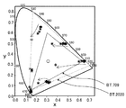
- the color gamut refers to a specific range in the visible region, for example, as shown in FIG. 13, the XYZ color system (CIE1931-XYZ color system) defined by the CIE (Commission Internationale de l'Eclairage). It can be represented using the xy chromaticity diagram of. In the xy chromaticity diagram, the color gamut can be indicated by a triangle that defines the chromaticity coordinates that are the vertices of each of the colors R, G, and B and connects each of them with a straight line.
- the color gamut has been conventionally defined by various color gamut standards, and in the video industry including imaging equipment, for example, BT. 709 and BT. Standards that cover a wide color gamut, such as the 2020 standard, are used.
- the CIE standard light source D65 which is a white point, is shown by plot ⁇ .
- the imaging device uses, for example, a color chart as disclosed in Patent Document 1 to compare the reproduced color on the imaging device with the reproduced color on the color chart. If there is a difference in the reproduced color, it is calibrated based on the above color chart.
- the colors are designed by assigning the values of RGB values (0,0,0) to (255,255,255) in which the shades of each RGB color are divided stepwise. Met. Therefore, it was created as a color chart including the element of brightness (FIG. 14 (A)).
- FIG. 13 shows how the chromaticity position is shifted (the saturation is shifted) on the xy chromaticity diagram when the brightness is reduced (arrow in FIG. 13). Therefore, there has been a demand for a transmissive color gradation chart capable of performing more accurate color calibration.
- the present disclosure has been made in view of the above problems, and an object of the present disclosure is to provide a transmissive color gradation chart capable of performing accurate color calibration of an imaging device or the like.
- the present disclosure includes a color chart member having at least one color bar in which transmitted light exhibits a chromatic color, and a gray gradation chart member in which transmitted light exhibits achromatic color and has a plurality of transmission regions having different brightness.
- the color chart member and the gray gradation chart member are laminated so as to have an overlapping transmission region in which the color bar and the plurality of transmission regions overlap in a plan view. Provides a tone chart.
- the covering portion of the plurality of transmission regions is formed by using a black colorant or a metal. This is because it is possible to perform more precise color adjustment than those using a plurality of chromatic colors.
- the plurality of transmission regions are composed of transparent dot regions in which dots having light-shielding properties are randomly arranged. This is because the brightness can be adjusted more accurately.
- a spacer is arranged between the color chart member and the gray gradation chart member, and the spacer has an opening in the overlapping transmission region. This is because a gap corresponding to the thickness of the spacer is generated between the color chart member and the gray gradation chart member, and the appearance of the Newton ring can be suppressed.
- the angle of view of the imaging device calibrated by the transmissive color gradation chart is determined on the main surface of the color chart member different from the main surface on the gray gradation chart member side. It is preferable that a mark for determining the angle of view is formed.
- the color chart member side is used as the image pickup device side. Therefore, as described above, focusing on the color chart member surface has the effect of suppressing chromatic aberration. Because.
- the distance between the adjacent transmission regions in the plurality of transmission regions is half or more of the width of the transmission regions. This is because it is possible to prevent the intrusion of light leakage from the adjacent transmission region and enable more accurate calibration.
- the present disclosure provides a transmissive color gradation chart apparatus characterized by having two protective base materials and the above-mentioned transmissive color gradation chart sandwiched between the two protective base materials. To do. As a result, adhesion of solvent and the like to the color chart member and the gray gradation chart member and physical contact can be suppressed, and the color density of the color bar of the color chart member is lowered or the pigment is changed. It is possible to suppress the occurrence of problems such as.
- the gray gradation chart structure in which a plurality of transmission regions having different brightness are arranged is a gray gradation chart in which the plurality of transmission regions are laminated so as to overlap in a plan view.
- the plurality of transmission regions provide a gray gradation chart characterized in that the dots having a light-shielding property are composed of dot regions having transparency in which dots having a light-shielding property are randomly arranged. According to the present disclosure, there is an effect that the brightness, that is, the light transmittance can be accurately and easily calibrated into a gray gradation chart.
- the distance between adjacent dot regions is at least half the width of the dot regions. This is because it is possible to prevent the intrusion of light leakage from the adjacent dot region and enable more accurate calibration.
- the transmissive color gradation chart of the present disclosure has an effect that color adjustment including brightness can be performed precisely and easily, and accurate color calibration of an imaging device or the like can be performed.
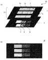
- (A) is a schematic view showing an example of the transmissive color gradation chart of the present disclosure
- (B) is a schematic top view of the transmissive color gradation chart of the present disclosure.
- (A) is a schematic top view showing an example of the color chart member in the present disclosure
- (B) is an image graph showing the transmittance for each wavelength shown by the color chart member of FIG. 2 (A).
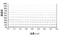
- (A) is a schematic top view showing an example of the gray gradation chart member in the present disclosure
- (B) is an image graph showing the transmittance for each wavelength shown by the gray gradation chart member of FIG. 3 (A). It is an xy chromaticity diagram which shows the color gamut of the transmission type color gradation chart of this disclosure.
- the present inventors have found that, as shown in FIG. 14B, the transmission spectrum of the conventional color chart member shifts in peak wavelength as the transmittance decreases, and noise is generated. That is, it has been found that the color chart member produced based on the RGB value design has a saturation shift especially at low brightness.
- the inventors of the present disclosure have conducted intensive research, and found that the color chart member and the gray gradation chart member are combined and superposed to adjust the brightness and the saturation. We have found that it is a transmissive color gradation chart that can be performed at the same time and can perform accurate color calibration of the imaging device.
- the transmissive color gradation chart of the present disclosure will be described below.
- the transmission-type color gradation chart of the present disclosure includes a color chart member having at least one color bar in which transmitted light exhibits a chromatic color, and a plurality of transmission-type color gradation charts in which transmitted light exhibits achromatic color and different brightness.
- the color chart member and the gray gradation chart member have a gray gradation chart member having a transmission region, and have an overlapping transmission region in which the color bar and the plurality of transmission regions overlap in a plan view. It is characterized in that and is laminated.
- FIG. 1A is an explanatory diagram for explaining the transmissive color gradation chart of the present disclosure
- FIG. 1B is a schematic top view of the transmissive color gradation chart of the present disclosure.
- the transmissive color gradation chart 10 of the present disclosure is a color chart having a transparent substrate 5 and a color bar 3 having at least one chromatic color formed on the transparent substrate 5. It has a member 1 and a gray gradation chart member 2 which is achromatic and has a plurality of transmission regions 4 having different light transmittances, and the color chart member 1 and the gray gradation chart member 2 are at least a color chart. It is determined that one or more color bars 3 in the member 1 and a plurality of transmission regions 4 having different transmittances in the gray gradation chart member 2 are arranged so as to have an overlapping transmission region which is an overlapping region in a plan view. It is a feature.
- FIGS. 1A and 1B three transmission regions 4 are arranged so as to overlap each color bar in a plan view, and nine transmission regions 4 overlap each other in a plan view as a whole. It shows how they are arranged.
- the transmissive color gradation chart 10 has nine calibration patches.
- each configuration of the transmissive color gradation chart of the present disclosure will be described.
- FIG. 2A is a schematic top view showing an example of the color chart member in the present disclosure.
- FIG. 2B is an image graph showing an example of the transmittance for each wavelength shown by the color chart member of FIG. 2A.
- the color chart member 1 in the present disclosure has a transparent substrate (not shown) and a color bar 3 formed on the transparent substrate and exhibiting at least one chromatic color. ..
- a color bar 3 formed on the transparent substrate and exhibiting at least one chromatic color. ..
- the color bar group 33 is configured by arranging these four color bars in a pattern in no particular order.
- a light-shielding portion 6 for a color chart is provided around each color bar on the transparent substrate 5.
- a color chart holding frame 7 is arranged on the outer periphery of the color bar group 33 and the light-shielding portion 6 for the color chart.
- the white color bar 3W is usually transparent.
- Color Bars are those in which transmitted light exhibits a chromatic color, and at least one or more of them are formed. When color bars of a plurality of colors are formed, a group of color bars arranged in a pattern in no particular order is formed. Such a color bar is not particularly limited, but is usually formed on a transparent substrate.
- (A) Types of color bars As the color bars arranged in the color chart member used in the present disclosure, for example, as shown in FIG. 2 (A) described above, a total of four color bars (color bar group) having three primary colors and white color. ), Or only one color bar exhibiting one chromatic color. In the color chart member of the present disclosure, the number and type of color bars can be appropriately selected according to the intended use.
- BT. 709 or BT. When calibrating an image sensor capable of expressing a wide color gamut such as 2020, it is preferable to use a color chart member corresponding to this.
- the color bar group described in JP-A-2017-187756 can be adopted.
- the color chart member used for such an application will be described.
- the transmission type color chart member In the transmission type color chart member, light incident from the back surface is dispersed according to the selective transmission of color bars exhibiting chromatic colors excluding white (W) constituting the color bar group, and each color is dispersed in the visible light region. Transmission spectra of each appear.
- the color bar group of the color chart member in the present disclosure it is preferable that the transmission spectra of the color bars of each color have separate peak tops. “The transmission spectra of the color bars of each color have separate peak tops” means, for example, the colors of red (R), green (G), and blue (B), as shown in FIG. 2 (B). It means that the transmission spectrum of each color of the bar has an independent chevron waveform. This is because the brightness of the color bar group can be made uniform by making the transmission spectrum of each color bar constituting the color bar group a chevron waveform.
- the transmittance spectrum of each color bar is a colorless (transparent) white color using Olympus Co., Ltd.'s visible differential light measuring machine OSP-SP200 or Topcon Technohouse Co., Ltd. 2D spectroradiometer SR-5000 (light source is optional). It can be obtained by measuring the transmittance in the visible light region of 380 nm to 780 nm with the bar as the background.
- each color bar excluding W constituting the color bar group is arranged in a well-balanced manner with peaks at desired intervals in the visible light region.
- the color chart member of the following aspects described in JP-A-2017-187756 can be used. That is, it has a transparent substrate and a color bar group formed on the transparent substrate, and the color bar group has at least six colors of red, green, blue, first color, second color, and white.
- the bars are arranged in a pattern in no particular order, and the coordinate points of the first color are (0.351, 0.649), (0.547, 0.453), (0.547, 0.453) on the xy chromaticity diagram. It is in the area surrounded by the four points (0.380, 0.506) and (0.433, 0.464), and the coordinate points of the second color are (0.125) on the xy chromaticity diagram.
- the peak wavelength of the transmission spectrum is 600 nm or more and 680 nm or less
- the peak wavelength of the transmission spectrum of the green color bar is 495 nm or more and 570 nm or less
- the peak wavelength of the transmission spectrum of the blue color bar is 430 nm or more and 490 nm or less
- the first color bar (yellow (Ye)).
- the transmission spectrum of the first color bar and the transmission spectrum of the second color bar have separate peak tops, and can be a chevron waveform. Further, normally, the transmission spectra of the R, G, and B color bars also have separate peak tops, and can be formed into a chevron waveform.
- the peak wavelength position of the transmission spectrum of the color bar can be adjusted according to the type of the color bar and the method of forming the color bar. For example, when a dyeing substrate using one type of dye is used as a color bar, the peak wavelength of the transmission spectrum of the color bar can also be adjusted by adjusting the density of the dye.
- the peak wavelength of the transmission spectrum of the color bar can be adjusted by changing the blending ratio of the two kinds of dyes. It can. Specifically, if it is a green (G) color bar, it can be formed by a dyeing method using two kinds of a yellow dye and a blue dye, but when the peak wavelength is shifted to the long wavelength side, it is yellow.
- G green
- the peak wavelength position can be adjusted by increasing the compounding ratio of the blue dye.
- the color bar size and the like are not particularly limited, and can be appropriately designed so as to easily produce a desired effect according to the application of the transmissive color gradation chart of the present disclosure. ..
- the transmissive color gradation chart of the present disclosure can be sized according to the captured image to which it is applied. Specifically, when the transmissive color gradation chart of the present disclosure is used for color evaluation and color correction of an output image of a measurement sample captured through a microscope of a pathological imaging device, the magnification of the objective lens of the microscope is used. It is possible to obtain a color chart for micro-imaging in which a group of color bars having a size corresponding to the above is formed.
- transmissive color gradation chart of the present disclosure is used for color evaluation and color correction of an output image of a measurement sample imaged at the same magnification by an imaging device, for example, a color bar having a size corresponding to the captured image size is used. It can be a color chart for macro imaging in which a group is formed.
- the color bar can have a length of 250 mm to 3.5 mm in the major axis direction and a length of 190 mm to 0.8 mm in the minor axis direction.
- the color bars of each color are arranged in a pattern in no particular order.
- the arrangement pattern of each color bar it may be arranged in a line pattern as illustrated in FIGS. 1 and 2 (A), and although not illustrated, it is arranged in a grid pattern or a circular shape. May be good.
- the arrangement order of the color bars of each color is not particularly limited, and it can be appropriately designed so as to easily produce a desired effect according to the use of the transmissive color gradation chart of the present disclosure.
- each color bar may be divided into a plurality of regions 3a overlapping each transmission region 4 of the gray gradation chart member 2 described later in a plan view. , It does not have to be divided.
- the color chart light-shielding portion described later is arranged in the divided portion.
- Each color bar may be any member as long as it exhibits a desired transmission spectrum, and can be formed by using conventionally known methods such as a vapor deposition method, a dyeing method, a printing method, a transfer method, and an inkjet method.
- a dyeing method for example, a silver salt emulsion prepared by adding a solution of silver nitrate to gelatin is used, and the silver salt emulsion is applied onto a chip substrate such as a glass plate. It can be formed by desilvering a silver salt photographic plate obtained by drying and dyeing it with a dye corresponding to the color of the color bar.
- the dyeing substrate can be formed by mixing gelatin (solution) with a dye in advance and applying a material having a predetermined color to a chip substrate such as a glass plate.
- the color bar group can be formed, for example, by arranging each color bar formed by the above method on one side of a transparent substrate described later in a desired pattern and sandwiching the color bar group between the transparent substrate and the cover glass.
- the color bar of the present disclosure is not particularly limited, but one formed on the transparent substrate is preferable.
- the transparent substrate used in the present disclosure is not particularly limited as long as it can support a color bar group and a light-shielding portion for a color chart and has desired light transmission, and is used for a conventionally known color chart member. It can be the same as the transparent substrate to be used.
- an inorganic substrate such as a glass substrate or a resin substrate can be used.
- the resin substrate may be a film or a sheet as well as a plate.
- Light-shielding part for color chart The color chart member in the present disclosure is usually provided with a light-shielding part for color chart for defining a transmission region of the color bar.
- a light-shielding portion for a color chart include those in which a color bar is formed on the transparent substrate and is arranged on the transparent substrate so as to surround the color bar.
- the light-shielding portion 6 for a color chart shown in FIG. 2 (A) can be mentioned.
- a light-shielding cover arranged separately from the color bar may be used as a light-shielding portion for a color chart.
- the light-shielding portion for the color chart may be any one having a desired light-shielding property, and examples thereof include a metal film such as a chromium thin film and a printing layer formed of black ink.
- a conventionally known method can be used depending on the material used.
- the color chart shading portion in the present disclosure defines the divided color bars 3a when the color bars 3 are divided and formed, for example, as shown in FIG. 1 (A). It may be arranged so as to do so.
- the transmissive color gradation chart of the present disclosure is arranged so that the color chart member is located on the image pickup apparatus side at the time of use. Therefore, an angle-of-view determination mark for determining the angle of view of the image pickup apparatus is formed on the surface of the color chart member on the side opposite to the gray gradation chart member.
- FIG. 6 shows an example of the angle-of-view determination mark
- the angle-of-view determination mark 11 of the image pickup element is a color chart member so as to point to the boundary between the color chart light-shielding portion 6 and the color bar holding frame 7. It is provided on the surface opposite to the gray gradation chart member.
- the shape and size of the angle-of-view determination mark 11 of the image sensor is not particularly limited as long as it has a shape and size that can be recognized as a mark indicating the angle of view of the image sensor, and is a transmissive color. It is possible to make appropriate adjustments according to the design of the gradation chart and the like. On the other hand, since the gray gradation chart member is arranged so as to be located on the light source side, such a mark for determining the angle of view is not usually provided.
- the color chart member in the present disclosure may have an IR cut filter.
- each color bar is formed by a dyeing method, light tends to be easily transmitted in a wavelength region having a transmission spectrum of 650 nm or more due to the characteristics of the dye, and the dye has a high light transmittance.
- the dyes used for the yellow (Ye), orange (O), and red (R) color bars tend to hardly absorb light on the long wavelength side from around 650 nm. Therefore, in the long wavelength region, the transmission spectra of each color overlap.
- the transmission spectrum of each color can be separated, and color mixing can be prevented.
- the IR cut filter can be selected by examining the wavelength region to be blocked according to the transmission spectrum characteristics of each color bar.
- the IR cut filter a conventionally known one can be used.
- the color chart member in the present disclosure may include an alignment mark, a recognition code, a cover glass, a color bar holding frame, a transparent protective plate with a light-shielding portion, and the like.
- the recognition code can be, for example, a code that records information such as a test chart.
- the alignment mark can be a mark in which position information is recorded, but may also function as a recognition code in which information such as a test chart is recorded. These may be provided on a transparent protective plate with a light-shielding portion.
- FIG. 3A is a schematic top view showing an example of a gray gradation chart member.
- FIG. 3B is an image graph showing a transmission spectrum of each transmission region of the gray gradation chart member of FIG. 3A.
- the gray gradation chart member 2 in the present disclosure has a plurality of transmission regions 4 which are achromatic and have different brightness.
- eight brightness gradation regions having a total of eight transmission regions 4 having different brightness are formed.
- a light-shielding portion 6'for a gray gradation chart is provided around the brightness gradation region.
- a gray gradation chart holding frame 7' is arranged on the outer periphery of the light-shielding portion 6'for the gray gradation chart.
- the gray gradation chart member in the present disclosure has a plurality of transmission regions 4 having different light transmittances.
- the plurality of transmission regions in the gray gradation chart member are arranged so as to have at least a region that overlaps with one color bar in the color chart member in a plan view.
- the arrangement of the transmissive regions for each gradation having different transmittance is not particularly limited, but can be arranged in a row or in a grid pattern so that the transmittance changes stepwise. For example, it can be arranged so that the transmittance decreases from the maximum light transmittance portion (whitest portion) to the minimum light transmittance portion (blackest portion).
- one color bar 3 of the color chart member 1 and three transmission regions 4 of the gray gradation chart member 2 are arranged so as to overlap each other in a plan view.
- the transmission regions of 16 are arranged so as to overlap each other in a plan view.
- the number of transmission regions of the gray gradation chart member overlapping on one color bar in a plan view is not particularly limited as long as it is plural, but can be, for example, 2 or more and 256 or less.
- each transmission region is not particularly limited, but it can usually be a rectangular shape.
- the size of each transmission region can be appropriately designed so as to easily produce a desired effect according to the application of the transmission type color gradation chart of the present disclosure, and for example, 250 mm ⁇ 190 mm to 3.5 mm. It can be ⁇ 0.8 mm.
- a plurality of transmission regions having different light transmittances that overlap one color bar in a plan view may be continuously formed, but it is preferable that the transmission regions having different transmittances are separately formed. .. This is because the transmission regions having different transmittances are formed separately, so that the influence of the leaked light from the adjacent transmission regions can be prevented, so that accurate calibration can be performed.
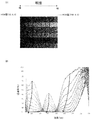
- FIG. 15 shows a light source having a brightness of 4500 cd / m 2 on an HDR (High Dynamic Range) gradation chip (corresponding to one transmission region of the gray gradation chart member) having a transmission region size of 10 mm ⁇ 10 mm. It is the result measured by the 2D spectroradiometer SR-5000 of Topcon Techno House Co., Ltd. (the distribution of brightness is displayed on a two-dimensional map) when irradiated with. As shown in FIG. 15, the amount of light leaking out of the transmission region is about 10% of the transmission region at a distance of 5 mm and is almost nonexistent at a distance of 10 mm.
- HDR High Dynamic Range
- the leakage of light to the outside of the transmission region is 10% of the transmission region at a distance of half the width of the transmission region from the edge of the transmission region. There is a degree, and there is almost no place where the distance is the same as the width of the transmission area.
- the luminance ratio shown on the vertical axis of the graph in the figure indicates the luminance ratio of the surrounding region when the luminance of the transmission region is 1.
- the distance between adjacent transmission regions having different transmittances is preferably half or more of the width of the transmission regions.
- the width is equal to or larger than the width of the transmission region.
- the width of the transparent region means the distance from the side of the transparent region adjacent to the transparent region to the side facing the transparent region among the sides that partition the transparent region.
- the gray gradation chart member is not particularly limited as long as it has a plurality of transmissive regions having different light transmittances, but is a transparent support having light transmissivity such as glass or film. Examples thereof include those in which a plurality of metal films having different thicknesses are formed on the transparent support, those in which a striped or netted covering portion is formed on a transparent support, a silver salt film and a laminate thereof.
- FIG. 16 shows an example of the covering portion, and shows an enlarged example in which the halftone dot-shaped covering portion 41 is formed in the transmission region 4.
- the covering portion in the plurality of transmission regions is formed by using a black colorant or black-colored paper, film, glass, or metal. This is because a light-shielding region formed by using a plurality of chromatic colors as a light-shielding region in the plurality of transmission regions may give saturation noise to the transmitted light.
- the gray gradation chart member in the present disclosure includes a transparent dot region in which dots having a light-shielding property are randomly arranged, and a light-shielding portion for a gray gradation chart arranged around the dot region. It is preferably a tone chart structure or a laminate of the gray gradation chart structure. This is because the brightness can be adjusted accurately, and moire can be prevented when the gray gradation chart structures are laminated in order to adjust the brightness accurately.
- the gray gradation chart structure will be described in detail in the section “C. Gray gradation chart” described later.
- gray gradation chart member Other methods for forming the gray gradation chart member include, for example, a sputtering method in which a plurality of metal films having different thicknesses are formed on a transparent support such as glass or a film, or a coating area on the transparent support. Examples thereof include a printing method, an inkjet method, a photolithography method, and the like, which can form different striped or halftone dot-shaped covering portions.
- the gray gradation chart member in the present disclosure preferably has a light-shielding portion for gray gradation chart provided on the outer periphery of a plurality of transmission regions or the outer circumference of each transmission region.
- a light-shielding portion for a gray gradation chart By providing a light-shielding portion for a gray gradation chart, it is possible to prevent light from wrapping around from the side.
- Examples of the light-shielding portion for the gray gradation chart include those similar to the above-mentioned “1.
- the area of the opening of the light-shielding portion for the color chart is smaller than the area of the opening of the light-shielding portion for the gray gradation chart.
- the color chart member and the gray gradation are formed so that the light-shielding portion for the color chart and the light-shielding portion for the gray gradation chart overlap in a plan view to form an overlapping transmission region. It is configured by stacking the chart members.
- the lighting device is placed on the gray gradation chart member side of the transmissive color gradation chart, and the imaging device is placed on the color chart member side. To place. This is because when the image pickup apparatus focuses on the transmissive color gradation chart, chromatic aberration can be suppressed by focusing on the surface of the color chart member.
- the imaging device if the area of the opening of the light-shielding portion for the color chart in the overlapping transmission region is equal to or larger than the area of the light-shielding portion for the gray gradation chart in the overlapping transmission region, calibration is performed by the imaging device. At that time, both the end portion of the light-shielding portion for the color chart and the end portion of the light-shielding portion for the gray gradation chart are photographed by the imaging device, which may cause a problem in focus adjustment or the like. Because.
- the plurality of transmission regions in the gray gradation chart member and the light-shielding portion for the gray gradation chart are not particularly limited, but are preferably formed on the transparent support. ..
- the transparent support is not particularly limited as long as it can support the plurality of transmission regions and the light-shielding portion for the gray gradation chart and has desired light transmission, and is conventionally known gray. It can be similar to the transparent substrate used for the scale. Specifically, an inorganic substrate such as a glass substrate or a resin substrate can be used.
- the resin substrate may be a film or a sheet as well as a plate.
- the gray gradation chart member in the present disclosure has an alignment mark, a cover glass, a gray gradation chart holding frame, a transparent protective plate with a light-shielding portion, and the like. May be good.
- the transmissive color gradation chart of the present disclosure preferably has a spacer arranged between the color chart member and the gray gradation chart member, and this spacer is viewed in plan on the color bar of the color chart member. It is preferable that the upper overlapping region has at least an opening. This is because by providing the spacer, a gap corresponding to the thickness of the spacer is generated between the color chart member and the gray gradation chart member, and the appearance of the Newton ring can be suppressed.
- the spacer include thick paper, a film, and the like having at least an opening in a region that overlaps the color bar in a plan view.
- the thickness of the spacer is appropriately adjusted according to the size of the gap to be provided between the color chart member and the gray gradation chart member, and is not particularly limited. Specifically, it may be 10 ⁇ m or more, preferably 20 ⁇ m or more. When the thickness of the spacer is within the above range, it is possible to provide a gap sufficient to suppress the application for Newton ring.
- the spacer may be the light-shielding cover described in the section "B. Transmissive color gradation chart device 2.
- Light-shielding cover described later.
- the light-shielding cover in this case may have functions as the light-shielding portion for the color chart and the light-shielding portion for the gray gradation chart, and is separate from the light-shielding object for the color chart and the light-shielding portion for the gray gradation chart. It may be provided.
- the transmissive color gradation chart of the present disclosure includes the color chart member described in the above-mentioned "1. Color chart member” and the gray gradation chart member described in the section "2. Gray gradation chart member”. At least one color bar in the color chart member and a plurality of transmission regions in the gray gradation chart member are arranged so as to have overlapping transmission regions that overlap in a plan view. And.
- the color chart member and the gray gradation chart member are overlapped with each other by using an adhesive or a jig for a separate process with the spacer or the like interposed therebetween, if necessary.
- it is carried out by a method using a solid adhesive capable of having voids or the like.
- the transmissive color gradation chart of the present disclosure has a plurality of calibration patches by superimposing "1. color chart member” and "2. gray gradation chart member” as described above. ..
- FIG. 4 shows an xy chromaticity diagram obtained by the transmissive color gradation chart of the present disclosure.
- the transmission spectrum of each calibration patch obtained by the transmission type color gradation chart of the present disclosure is shown in FIG.
- FIG. 4 it can be seen that the chromaticity position does not change substantially on the xy chromaticity diagram even if the brightness is reduced.
- FIG. 5 it can be seen that there is no deviation in the peak wavelength of the transmitted light and no noise even when the brightness is low.
- the transmissive color gradation chart of the present disclosure can be used, for example, for calibrating an imaging device such as a camera, that is, for evaluating color reproducibility.
- an imaging device such as a camera or the like.
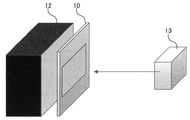
- the lighting fixture 12 is arranged on one surface side of the transmissive color gradation chart 10. Then, while the illumination device 12 irradiates the transmissive color gradation chart from one surface side, the camera 13 captures an image of the transmissive color gradation chart from the other surface side.
- the camera's arithmetic circuit After capturing the transmissive color gradation chart, the camera's arithmetic circuit compares the calibration patch on the captured image with the reference color patch stored in the camera's storage in advance to determine the chromaticity of both. Calculate the evaluation value of the color reproducibility of the camera based on this. After calculating the evaluation value of the color reproducibility, the color correction circuit of the camera calibrates the camera by correcting the parameters of the camera that correlate with the color reproducibility so that the color difference is minimized.
- the transmissive color gradation chart of the present disclosure is used by arranging the color chart member on the camera side and the gray gradation chart member on the lighting device side. This is because when the camera focuses on the chart, chromatic aberration can be suppressed by focusing on the surface of the color chart member.
- the transmissive color gradation charts of the present disclosure can be used for imaging devices, video devices, and peripheral devices that require color calibration in general. Above all, it can be suitably used for a pathological imaging device.
- the transmissive color gradation chart device of the present disclosure has two protective base materials and the above-mentioned transmissive color gradation chart sandwiched between the two protective base materials. It is characterized by.
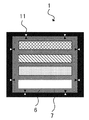
- FIG. 7 is a schematic diagram showing an example of the transmissive color gradation chart device of the present disclosure.
- the transmissive color gradation chart device 100 of the present disclosure includes the transmissive color gradation chart 10 and the protecting base material 101 (protecting base material 101) arranged on the color chart member 1 side of the transmissive color gradation chart.
- the transmissive color gradation chart device 100 of the present disclosure includes the transmissive color gradation chart 10 and the protecting base material 101 (protecting base material 101) arranged on the color chart member 1 side of the transmissive color gradation chart.
- a first protective base material a protective base material 102
- a second protective base material arranged on the gray gradation chart member 2 side of the transmissive color gradation chart.
- the first protective base material 101 and the second protective base material 102 are arranged so as to face each other via the color bar in the color chart member and the plurality of transmission regions in the gray gradation chart member, and the color bar in the color chart member. It has at least a transmissive portion in a region that overlaps in plan view.
- the two protecting groups in the present disclosure are arranged so as to face each other via a transmissive color gradation chart.
- the protective base material is preferably a member having at least a transmissive portion in a region of the color chart member that overlaps the color bar in a plan view.
- the "transmissive portion” means a region that transmits at least visible light.
- the size of the protective base material is appropriately selected according to the size of the transmissive color gradation chart device of the present disclosure, and is not particularly limited.
- the material used for the protective base material is preferably, for example, a material capable of protecting the color chart member and the gray gradation chart member sandwiched between the pair of protective base materials from scratches and dust.
- a specific protective base material for example, a transparent base material such as glass or plastic can be mentioned.
- glass is usually used as the material of the protective base material.
- a transparent protective plate with a light-shielding portion which has a light-shielding portion having the same pattern as the light-shielding cover described later, can also be used.
- the transmissive color gradation chart apparatus of the present disclosure is between the first protective base material 101 and the transmissive color gradation chart 10, and with the second protective base material 102. It is preferable that the light-shielding covers 103 and 104 are arranged between the transmissive color gradation chart 10 and the light-shielding covers 103 and 104.
- the light-shielding cover 103 between the first protective base material 101 and the transmissive color gradation chart 10 is placed between the first light-shielding cover and the second protective base material 102 and the transmissive color gradation chart 10.
- the light-shielding cover 104 is referred to as a second light-shielding cover.
- the spacer of the transmissive color gradation chart described above can be configured by the third light-shielding cover 105.
- Examples of the first to third light-shielding covers include thick paper, film, and the like having at least an opening in a region of the color chart member that overlaps the color bar in a plan view.
- the openings of the light-shielding covers may be formed at the predetermined positions described above.
- the positions and widths of the openings in the light-shielding covers may be the same or different.
- the positions and widths of the openings of the light-shielding covers can be the same. This is because the outline of the color bar becomes clear, and a higher quality transmissive color gradation chart device can be obtained.
- the above-mentioned spacer (third light-shielding cover) and the second light-shielding cover can be viewed from the observation side (camera side) of the transmissive color gradation chart device. It is preferable that no region is observed.
- the width of the opening of the first light-shielding cover 103 is w 1
- the width of the opening of the spacer (third light-shielding cover 105) is w 2
- the width of the second light-shielding cover is w 2.
- the width of the opening of 104 was w 3, it is preferable to satisfy the relationship of w1 ⁇ w2 ⁇ w3. By doing so, it is possible to prevent light leakage of light incident at an angle.
- the first light-shielding cover 103 and the second light-shielding cover 104 also function as spacers, and Newton is generated due to contact between the protective base material and the transmissive color gradation chart. It is possible to suppress the ring. Further, the third light-shielding cover 105 also functions as a spacer, and it is possible to suppress Newton ring generated due to contact between the color chart member and the gray gradation chart member.
- the specific size of the light-shielding cover and the width of the opening are appropriately adjusted according to the design of the transmissive color gradation chart device, and are not particularly limited.
- the transmissive color gradation chart used in the transmissive color gradation chart apparatus of the present disclosure may be the same as the content described in the above "A. Transmissive color gradation chart". Since it can be done, the description here is omitted.
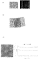
- the conventional gray gradation chart uses regular halftone dots and line-and-space patterns. Therefore, the gray gradation chart using such a regular pattern has transmittance adjustment. It was newly found that the problem of the occurrence of interference fringes (moire) arises when they are overlapped for the sake of.
- FIG. 8 (A) shows an interference manuscript that occurs when regular halftone dots are used
- FIG. 8 (B) shows an interference manuscript that occurs when a line and space pattern is used.
- the transmittance may change finely.
- the transmittance is different for each wavelength, there is a problem that a problem may occur when the gray gradation chart member of the transmission type color gradation chart described above is used in combination with the color chart member. ..
- FIG. 8C shows the transmittance of the gray gradation chart of FIG. 8A for each wavelength.
- the present invention and the like are a gray gradation chart structure in which a plurality of transparent regions having different brightness are arranged, and the plurality of transparent regions are transparent dot regions in which dots having light-shielding properties are randomly arranged.
- the above problem is solved by using a gray gradation chart structure composed of and laminating it.
- the gray gradation chart of the present disclosure is a gray gradation in which a gray gradation chart structure in which a plurality of transmission regions having different brightness are arranged is laminated so that the plurality of transmission regions overlap in a plan view.
- the chart is characterized in that the plurality of transmission regions are composed of transparent dot regions in which light-shielding dots are randomly arranged.
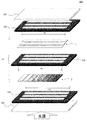
- FIG. 9A is a schematic plan view of each layer (gray gradation chart structure) of the gray gradation chart in which the four gray gradation chart structures 21 from the first layer to the fourth layer are laminated.
- 9 (B) is an enlarged view of a dot region in which dots having a light-shielding property are randomly arranged.
- the gray gradation chart structure 21 includes a transparent dot region 22 in which dots having light-shielding properties are randomly arranged, and a gray gradation chart structure light-shielding portion 23 in which the dots are not arranged.
- FIG. 10 shows the transmittance of each transmission region of the gray gradation chart of the present disclosure.
- the transmittance of the gray gradation chart of the present disclosure is substantially constant for each wavelength. Therefore, when used in combination with the color chart member, that is, when used as the gray gradation chart member of the transmissive color gradation chart described above, the saturation and brightness can be adjusted at the same time, and the adjustment can be performed quickly and accurately. It will be possible.
- FIG. 9C shows a schematic top view of a transmissive color gradation chart in which the gray gradation chart of the present disclosure is superimposed on a color chart member.
- the gray gradation chart structure includes a transparent dot region in which dots having a light-shielding property are randomly arranged and a gray gradation chart structure light-shielding portion having a light-shielding property. As shown in FIG. 9A, the gray gradation chart structure has a plurality of dot regions defined by a light-shielding portion of the gray gradation chart structure.
- Such a gray gradation chart structure is used as a gray gradation chart by stacking a plurality of layers of the gray gradation chart structure in which the dot regions are arranged in parallel. At this time, the lengths of the stacked gray gradation chart structures in the direction perpendicular to the parallel direction of the dot regions arranged in parallel are different, and the number of dot regions of each gray gradation chart structure is different. Is preferably different.
- the length in the direction perpendicular to the parallel direction of the dot regions that is, the number of dot regions of the gray gradation chart structure is sequentially changed. Is preferable.
- a laminating method in this case for example, as shown in FIG. 9A, a method of laminating the gray gradation chart structure so that one end side in the longitudinal direction is aligned can be mentioned.
- the number of layers of the gray gradation chart structure is large on the right side of the drawing, and the transmittance in the transmission region of the gray gradation chart is low.
- the number of layers of the gray gradation chart structure is small, and the transmittance in the transmission region of the gray gradation chart is high.
- Dot area is a transparent area in which dots having a light-shielding property are randomly arranged. Random is a state in which the arrangement does not have periodicity as if it were completely arranged. Specifically, random numbers can be generated and placed using the Mersenne Twister or the error diffusion method.
- the randomization be a random arrangement that does not repeat within the dot region or between the overlapping dot regions.
- the transmittance of the dot area can be adjusted by adjusting the density of the included dots. It is preferable to have a plurality of dot regions per gray gradation chart structure. In this case, the plurality of dot regions in the gray gradation chart structure of 1 may have the same dot density (same transmittance) or different dot densities (different transmittances). Good).
- the plan view shape of the dots is not particularly limited, but it is preferably a shape including a substantially quadrangular shape, a substantially circular shape, a rectangular shape, or a circle.
- the size of the dots is not particularly limited, but it is preferable that the size does not resolve even if the image is taken at 8K resolution. Specifically, it is preferable that the image is not resolved even if the image is taken at a distance of 50 cm from the camera with respect to the effective surface of the 230 mm ⁇ 170 mm test chart at 8K resolution (number of pixels, horizontal 7680 ⁇ vertical 4320). Therefore, it is preferably about 30 ⁇ m (230 mm / 7680) ⁇ 40 ⁇ m (170 mm / 4320) or less.
- the lower limit is not particularly limited, but it is preferably 2 ⁇ m or more at which the wavelength does not change even in the near infrared wavelength.
- the dot region can be obtained by forming a random dot pattern on a support such as a transparent substrate or film by a printing method, a lithography method (drawing method), or the like.
- the plan view shape of the dot region is not particularly limited, but for example, as shown in FIG. 9A, the brightness is sequentially changed and arranged in a line shape, specifically, the plan view shape is rectangular. , Elliptical or oval dot regions are preferably arranged in parallel. Further, as shown in FIG. 3, it may be arranged in a plurality of rows.
- the distance from the adjacent dot region ((d) in FIG. 9) is preferably half or more of the width of the dot region, and particularly the dots. It is preferably equal to or greater than the width of the region.
- Gray gradation chart member (1) Multiple transparent regions (a) Multiple transparent regions Since it is the same as that described in the section "Shape", the description here will be omitted. In the above description, the dot region is described as a transparent region.
- Gray gradation chart structure light-shielding portion in order to avoid wraparound of light, a gray gradation chart structure light-shielding portion having a light-shielding property is provided around the dot region. It is preferable to have. Further, it is preferable to form a light-shielding region also on the end face of the gray gradation chart structure.
- the light-shielding portion of the gray gradation chart structure the same as the above-mentioned "A. Transmissive color gradation chart 2.
- Gray gradation chart member (2) Light-shielding portion for gray gradation chart is exemplified.
- Gray Gradation Chart The gray gradation chart of the present disclosure is obtained by superimposing gray gradation chart structures so that the dot regions of the plurality of gray gradation chart structures described above overlap in a plan view, and each gray scale.
- the transparency of each transmission region can be adjusted by the dot density of the dot region in the tone chart structure, the number of gray gradation chart structures to be overlapped, and the overlapping method. Therefore, the brightness of the transmitted light can be precisely adjusted, and a gray gradation chart having a plurality of transmission regions having different brightness, that is, light transmittance can be easily manufactured.
- the horizontal axis represents the number (gray step) of each transmission region of the gray gradation chart of the present disclosure
- the vertical axis represents the brightness of the transmitted light indicated by each transmission region.
- a brightness of 0.005 cd / m 2 can be accurately realized. Further, for example, if the minimum difference in brightness between the plurality of transmission regions in the low brightness region is 0.005 cd / m 2, it can be formed.
- the gray gradation chart of the present disclosure may include a cover glass, a gray gradation chart structure holding frame, a transparent protective plate with a light-shielding portion, and the like.
- the gray gradation chart of the present disclosure can be used for imaging devices, super high-definition (4K, 8K HDR) compatible cameras, etc. that require fine adjustment of brightness. It can also be used as the above-mentioned "A. Transmissive color gradation chart 2. Gray gradation chart member”.
- the present invention is not limited to the above embodiment.
- the above embodiment is an example, and any one having substantially the same configuration as the technical idea described in the claims of the present invention and exhibiting the same effect and effect is the present invention. It is included in the technical scope of the invention.
Abstract
Description
本開示によれば、明度、すなわち光の透過率を精密かつ容易に較正可能なグレー階調チャートとすることができるといった効果を奏する。 Further, in the present disclosure, the gray gradation chart structure in which a plurality of transmission regions having different brightness are arranged is a gray gradation chart in which the plurality of transmission regions are laminated so as to overlap in a plan view. The plurality of transmission regions provide a gray gradation chart characterized in that the dots having a light-shielding property are composed of dot regions having transparency in which dots having a light-shielding property are randomly arranged.
According to the present disclosure, there is an effect that the brightness, that is, the light transmittance can be accurately and easily calibrated into a gray gradation chart.
一方、従来のRGBの濃淡によるRGB値設計で作製したカラーチャート部材を詳細に解析してみると、同じ色で明度のみを落とす設計とした場合、実物は彩度にずれが発生してしまう、という問題が生じていることを本発明者等は見出した。 As described above, in recent years, the colors reproduced by an image pickup device have become wider in color gamut, and the color calibration of an image pickup device is also required to have higher accuracy.
On the other hand, a detailed analysis of the color chart member produced by the conventional RGB value design based on the shade of RGB shows that if the design is such that only the brightness is reduced with the same color, the actual product will have a difference in saturation. The present inventors have found that the problem has arisen.
本開示の透過型カラー階調チャートは、透過光が有彩色を呈するカラーバーを少なくとも1つ有するカラーチャート部材と、透過光が無彩色を呈し、かつ明度が異なる複数の透過領域を有するグレー階調チャート部材と、を有し、上記カラーバーと、上記複数の透過領域とが平面視上重なる重複透過領域を有するように、上記カラーチャート部材と上記グレー階調チャート部材とが積層されてなることを特徴とする。 A. Transmission-type color gradation chart The transmission-type color gradation chart of the present disclosure includes a color chart member having at least one color bar in which transmitted light exhibits a chromatic color, and a plurality of transmission-type color gradation charts in which transmitted light exhibits achromatic color and different brightness. The color chart member and the gray gradation chart member have a gray gradation chart member having a transmission region, and have an overlapping transmission region in which the color bar and the plurality of transmission regions overlap in a plan view. It is characterized in that and is laminated.
以下、本開示の透過型カラー階調チャートの各構成について説明する。 In FIGS. 1A and 1B, three
Hereinafter, each configuration of the transmissive color gradation chart of the present disclosure will be described.
本開示におけるカラーチャート部材は、透過光が有彩色を呈するカラーバーを少なくとも1つ有するものである。本開示の透過型カラー階調チャートについて、図を参照して説明する。図2(A)は、本開示におけるカラーチャート部材の一例を示す概略上面図である。図2(B)は、図2(A)のカラーチャート部材が示す波長ごとの透過率の一例を示すイメージグラフである。 1. 1. Color Chart Member The color chart member in the present disclosure has at least one color bar in which transmitted light exhibits a chromatic color. The transmissive color gradation chart of the present disclosure will be described with reference to the drawings. FIG. 2A is a schematic top view showing an example of the color chart member in the present disclosure. FIG. 2B is an image graph showing an example of the transmittance for each wavelength shown by the color chart member of FIG. 2A.
以下、このようなカラーチャート部材について、詳細に説明する。 As illustrated in FIG. 2A, the
Hereinafter, such a color chart member will be described in detail.
本開示におけるカラーバーは、透過光が有彩色を呈するものであり、少なくとも1以上形成されるものである。複数色のカラーバーが形成されている場合、順不同でパターン状に配列されたカラーバー群を構成する。
このようなカラーバーは特に限定されるものでは無いが、通常、透明基板上に形成されている。 (1) Color Bars The color bars in the present disclosure are those in which transmitted light exhibits a chromatic color, and at least one or more of them are formed. When color bars of a plurality of colors are formed, a group of color bars arranged in a pattern in no particular order is formed.
Such a color bar is not particularly limited, but is usually formed on a transparent substrate.
本開示に用いられるカラーチャート部材に配置されるカラーバーとしては、例えば上述した図2(A)に示すように三原色および白色を有する計4つのカラーバー(カラーバー群)であってもよく、一色の有彩色を呈する一つのカラーバーのみであってもよい。本開示におけるカラーチャート部材においては、用途に応じてカラーバーの数、および種類を適宜選択することができる。 (A) Types of color bars As the color bars arranged in the color chart member used in the present disclosure, for example, as shown in FIG. 2 (A) described above, a total of four color bars (color bar group) having three primary colors and white color. ), Or only one color bar exhibiting one chromatic color. In the color chart member of the present disclosure, the number and type of color bars can be appropriately selected according to the intended use.
即ち、透明基板と、上記透明基板上に形成されたカラーバー群と、を有し、上記カラーバー群は、赤、緑、青、第1色、第2色および白の少なくとも6色のカラーバーが、順不同でパターン状に配列されて構成され、上記第1色の座標点は、xy色度図上で(0.351、0.649)、(0.547、0.453)、(0.380、0.506)、(0.433、0.464)の4点に囲まれた領域内にあり、上記第2色の座標点は、xy色度図上で、(0.125、0.489)、(0.112、0.229)、(0.270、0.407)、(0.224、0.242)の4点に囲まれる領域内にあり、赤色カラーバーの透過スペクトルのピーク波長が600nm以上680nm以下、緑色カラーバーの透過スペクトルのピーク波長が495nm以上570nm以下、青色カラーバーの透過スペクトルのピーク波長が430nm以上490nm以下、第1色カラーバー(黄(Ye)カラーバー)の透過スペクトルのピーク波長が540nm以上595nm以下、第2色カラーバー(シアン(Cy)カラーバー)の透過スペクトルのピーク波長が470nm以上515nm以下であるカラーチャート部材を使用することができる。 Specifically, the color chart member of the following aspects described in JP-A-2017-187756 can be used.
That is, it has a transparent substrate and a color bar group formed on the transparent substrate, and the color bar group has at least six colors of red, green, blue, first color, second color, and white. The bars are arranged in a pattern in no particular order, and the coordinate points of the first color are (0.351, 0.649), (0.547, 0.453), (0.547, 0.453) on the xy chromaticity diagram. It is in the area surrounded by the four points (0.380, 0.506) and (0.433, 0.464), and the coordinate points of the second color are (0.125) on the xy chromaticity diagram. , 0.489), (0.112, 0.229), (0.270, 0.407), (0.224, 0.242) in the area surrounded by the four points of the red color bar. The peak wavelength of the transmission spectrum is 600 nm or more and 680 nm or less, the peak wavelength of the transmission spectrum of the green color bar is 495 nm or more and 570 nm or less, the peak wavelength of the transmission spectrum of the blue color bar is 430 nm or more and 490 nm or less, and the first color bar (yellow (Ye)). ) It is possible to use a color chart member in which the peak wavelength of the transmission spectrum of the color bar) is 540 nm or more and 595 nm or less, and the peak wavelength of the transmission spectrum of the second color bar (cyan (Cy) color bar) is 470 nm or more and 515 nm or less. it can.
例えば、1種の染料を用いた染色基板をカラーバーとして用いる場合であれば、染料の濃度を調整することで、カラーバーの透過スペクトルのピーク波長も調整できる。 When forming each color bar, the peak wavelength position of the transmission spectrum of the color bar can be adjusted according to the type of the color bar and the method of forming the color bar.
For example, when a dyeing substrate using one type of dye is used as a color bar, the peak wavelength of the transmission spectrum of the color bar can also be adjusted by adjusting the density of the dye.
カラーバーのサイズ等については特に限定されず、本開示の透過型カラー階調チャートの用途等に応じて所望の効果を奏しやすくなるように、適宜設計することができる。例えば、本開示の透過型カラー階調チャートは、適応される撮像画像に応じて、サイズを設計することができる。具体的には、本開示の透過型カラー階調チャートを、病理用撮像機器の顕微鏡を介して撮像された測定試料の出力画像の色評価および色補正に使用する場合、顕微鏡の対物レンズの倍率に応じたサイズのカラーバー群が形成されたミクロ撮像用カラーチャートとすることができる。 (B) Color bar size The color bar size and the like are not particularly limited, and can be appropriately designed so as to easily produce a desired effect according to the application of the transmissive color gradation chart of the present disclosure. .. For example, the transmissive color gradation chart of the present disclosure can be sized according to the captured image to which it is applied. Specifically, when the transmissive color gradation chart of the present disclosure is used for color evaluation and color correction of an output image of a measurement sample captured through a microscope of a pathological imaging device, the magnification of the objective lens of the microscope is used. It is possible to obtain a color chart for micro-imaging in which a group of color bars having a size corresponding to the above is formed.
本開示におけるカラーバー群において、各色カラーバーは順不同でパターン状に配列される。各色カラーバーの配列パターンとしては、図1、および図2(A)で例示するように一列にラインパターン状に配列されていてもよく、例示しないが格子パターン状や円形状に配列されていてもよい。また、各色カラーバーの配列順については特に限定されず、本開示の透過型カラー階調チャートの用途等に応じて所望の効果を奏しやすくなるように、適宜設計することができる。 (C) Others In the color bar group in the present disclosure, the color bars of each color are arranged in a pattern in no particular order. As the arrangement pattern of each color bar, it may be arranged in a line pattern as illustrated in FIGS. 1 and 2 (A), and although not illustrated, it is arranged in a grid pattern or a circular shape. May be good. Further, the arrangement order of the color bars of each color is not particularly limited, and it can be appropriately designed so as to easily produce a desired effect according to the use of the transmissive color gradation chart of the present disclosure.
上述したように、カラーバーが複数に分割されている場合、通常、後述するカラーチャート用遮光部が、上記分割部分に配置されていることが好ましい。 As shown in FIG. 1A, each color bar may be divided into a plurality of regions 3a overlapping each
As described above, when the color bar is divided into a plurality of parts, it is usually preferable that the color chart light-shielding portion described later is arranged in the divided portion.
本開示のカラーバーは、特に限定されるものではないが、透明基板上に形成されたものが好ましい。本開示に用いられる透明基板としては、カラーバー群およびカラーチャート用遮光部を支持することができ、所望の光透過性を有するものであれば特に限定されず、従来公知のカラーチャート部材に用いられる透明基板と同様とすることができる。具体的には、ガラス基板等の無機基板や樹脂基板を用いることができる。樹脂基板は、板状の他、フィルムやシートであってもよい。 (2) Transparent Substrate The color bar of the present disclosure is not particularly limited, but one formed on the transparent substrate is preferable. The transparent substrate used in the present disclosure is not particularly limited as long as it can support a color bar group and a light-shielding portion for a color chart and has desired light transmission, and is used for a conventionally known color chart member. It can be the same as the transparent substrate to be used. Specifically, an inorganic substrate such as a glass substrate or a resin substrate can be used. The resin substrate may be a film or a sheet as well as a plate.
本開示におけるカラーチャート部材は、通常、上記カラーバーの透過領域を画定するためのカラーチャート用遮光部が設けられる。
このようなカラーチャート用遮光部としては、例えばカラーバーが上記透明基板上に形成されたものであれば、その周囲を囲うように上記透明基板上に配置されたものを挙げることができる。具体的には、図2(A)に示すカラーチャート用遮光部6を挙げることができる。 (3) Light-shielding part for color chart The color chart member in the present disclosure is usually provided with a light-shielding part for color chart for defining a transmission region of the color bar.
Examples of such a light-shielding portion for a color chart include those in which a color bar is formed on the transparent substrate and is arranged on the transparent substrate so as to surround the color bar. Specifically, the light-shielding
上記カラーチャート用遮光部としては、所望の遮光性を有するものであればよく、例えば、クロム薄膜等の金属膜、黒色インキで形成された印刷層等が挙げられる。
上記カラーチャート用遮光部の形成方法については、使用する材料に応じて従来公知の方法を用いることができる。 Further, as shown in FIG. 7, a light-shielding cover arranged separately from the color bar may be used as a light-shielding portion for a color chart.
The light-shielding portion for the color chart may be any one having a desired light-shielding property, and examples thereof include a metal film such as a chromium thin film and a printing layer formed of black ink.
As the method for forming the light-shielding portion for the color chart, a conventionally known method can be used depending on the material used.
本開示の透過型カラー階調チャートは、使用時には、撮像装置側にカラーチャート部材が位置するように配置される。そのため、カラーチャート部材の上記グレー階調チャート部材とは反対側の表面には、撮像装置の画角を決定するための画角決定用マークが形成される。図6は、画角決定用マークの一例を示すものであり、カラーチャート用遮光部6とカラーバー保持枠7との境界を指し示すように撮像素子の画角決定用マーク11が、カラーチャート部材の上記グレー階調チャート部材とは反対側の表面に設けられている。 (4) Mark for determining angle of view The transmissive color gradation chart of the present disclosure is arranged so that the color chart member is located on the image pickup apparatus side at the time of use. Therefore, an angle-of-view determination mark for determining the angle of view of the image pickup apparatus is formed on the surface of the color chart member on the side opposite to the gray gradation chart member. FIG. 6 shows an example of the angle-of-view determination mark, and the angle-of-
一方、グレー階調チャート部材は光源側に位置するように配置されるため、通常、このような画角決定用マークは設けられない。 The shape and size of the angle-of-
On the other hand, since the gray gradation chart member is arranged so as to be located on the light source side, such a mark for determining the angle of view is not usually provided.
また、本開示におけるカラーチャート部材は、IRカットフィルターを有していてもよい。各色カラーバーが染色法により形成される場合、染料の特性上、透過スペクトルが650nm以上の波長領域において光を透過しやすい傾向があり、高い光透過率を有してしまう。特にイエロー(Ye)、オレンジ(O)、およびレッド(R)のカラーバーに用いられる染料は、650nm付近から長波長側の光を吸収しにくい傾向にある。このため、長波長域では、各色の透過スペクトルが重複してしまう。 (5) Others The color chart member in the present disclosure may have an IR cut filter. When each color bar is formed by a dyeing method, light tends to be easily transmitted in a wavelength region having a transmission spectrum of 650 nm or more due to the characteristics of the dye, and the dye has a high light transmittance. In particular, the dyes used for the yellow (Ye), orange (O), and red (R) color bars tend to hardly absorb light on the long wavelength side from around 650 nm. Therefore, in the long wavelength region, the transmission spectra of each color overlap.
IRカットフィルターは、各色カラーバーの透過スペクトル特性に合わせて、遮断する波長領域を検討して選択することができる。IRカットフィルターは、従来公知のものを用いることができる。 On the other hand, by matching the color bar with an IR cut filter that removes a predetermined region, the transmission spectrum of each color can be separated, and color mixing can be prevented.
The IR cut filter can be selected by examining the wavelength region to be blocked according to the transmission spectrum characteristics of each color bar. As the IR cut filter, a conventionally known one can be used.
認識コードは、例えば、テストチャートの情報等を記録したコードとすることができる。また、アライメントマークは、位置情報が記録されたマークとすることができるが、さらにテストチャートの情報等が記録された認識コードとして機能してもよい。これらは、遮光部付きの透明保護板上に設けられていてもよい。 In addition to the above-described configuration, the color chart member in the present disclosure may include an alignment mark, a recognition code, a cover glass, a color bar holding frame, a transparent protective plate with a light-shielding portion, and the like.
The recognition code can be, for example, a code that records information such as a test chart. Further, the alignment mark can be a mark in which position information is recorded, but may also function as a recognition code in which information such as a test chart is recorded. These may be provided on a transparent protective plate with a light-shielding portion.
本開示におけるグレー階調チャート部材について、図を参照して説明する。図3(A)は、グレー階調チャート部材の一例を示す概略上面図である。図3(B)は、図3(A)のグレー階調チャート部材の各透過領域の透過スペクトルを示すイメージグラフである。 2. Gray Gradation Chart Member The gray gradation chart member in the present disclosure will be described with reference to the drawings. FIG. 3A is a schematic top view showing an example of a gray gradation chart member. FIG. 3B is an image graph showing a transmission spectrum of each transmission region of the gray gradation chart member of FIG. 3A.
以下、このようなグレー階調部材について詳細に説明する。 As illustrated in FIG. 3A, the gray
Hereinafter, such a gray gradation member will be described in detail.
図3(A)に示すように、本開示におけるグレー階調チャート部材は、光透過率が異なる複数の透過領域4を有するものである。グレー階調チャート部材における複数の透過領域は、少なくとも、上記カラーチャート部材における1つのカラーバーと平面視上重なる領域を有するように配置される。 (1) Multiple Transmission Regions As shown in FIG. 3A, the gray gradation chart member in the present disclosure has a plurality of
透過率の異なる階調毎の透過領域の配列としては特に限定されないが、透過率が段階的に変化するように一列または格子状に配列することができる。例えば、最大光透過率部(最白色部)から、最小光透過率部(最黒部分)にかけて透過率が低下するように配置することができる。 (A) Shape of a plurality of transmissive regions The arrangement of the transmissive regions for each gradation having different transmittance is not particularly limited, but can be arranged in a row or in a grid pattern so that the transmittance changes stepwise. For example, it can be arranged so that the transmittance decreases from the maximum light transmittance portion (whitest portion) to the minimum light transmittance portion (blackest portion).
各透過領域の大きさは、本開示の透過型カラー階調チャートの用途等に応じて所望の効果を奏しやすくなるように、適宜設計することができるが、例えば、250mm×190mm~3.5mm×0.8mmとすることができる。 The plan view shape of each transmission region is not particularly limited, but it can usually be a rectangular shape.
The size of each transmission region can be appropriately designed so as to easily produce a desired effect according to the application of the transmission type color gradation chart of the present disclosure, and for example, 250 mm × 190 mm to 3.5 mm. It can be × 0.8 mm.
なお、透過領域の幅とは、当該透過領域を区画する辺のうち、当該透過領域に隣接する透過領域側の辺から、当該辺に対向する辺までの距離を示すものとする。 From the above experimental results, when the transmission regions having different transmittances are separately formed, the distance between adjacent transmission regions having different transmittances is preferably half or more of the width of the transmission regions. In particular, it is preferable that the width is equal to or larger than the width of the transmission region.
The width of the transparent region means the distance from the side of the transparent region adjacent to the transparent region to the side facing the transparent region among the sides that partition the transparent region.
グレー階調チャート部材としては、光透過率が異なる複数の透過領域を有するものであれば特に限定されないが、ガラスやフィルムなどの光透過性を有する透明支持体上に厚さの異なる金属皮膜が複数形成されたものや、透明支持体上にストライプ状や網点状の被覆部が形成されたもの、銀塩フィルムやその積層物が挙げられる。
図16は、被覆部の一例を示すものであり、透過領域4において、網点状の被覆部41が形成された例を拡大して示すものである。 (B) Composition of a plurality of transmissive regions The gray gradation chart member is not particularly limited as long as it has a plurality of transmissive regions having different light transmittances, but is a transparent support having light transmissivity such as glass or film. Examples thereof include those in which a plurality of metal films having different thicknesses are formed on the transparent support, those in which a striped or netted covering portion is formed on a transparent support, a silver salt film and a laminate thereof.
FIG. 16 shows an example of the covering portion, and shows an enlarged example in which the halftone dot-shaped
上記グレー階調チャート構造体については、後述する「C.グレー階調チャート」の項で詳細に説明する。 The gray gradation chart member in the present disclosure includes a transparent dot region in which dots having a light-shielding property are randomly arranged, and a light-shielding portion for a gray gradation chart arranged around the dot region. It is preferably a tone chart structure or a laminate of the gray gradation chart structure. This is because the brightness can be adjusted accurately, and moire can be prevented when the gray gradation chart structures are laminated in order to adjust the brightness accurately.
The gray gradation chart structure will be described in detail in the section “C. Gray gradation chart” described later.
グレー階調チャート部材の形成方法としては、例えば、ガラスやフィルムなどの透明支持体に対して厚さの異なる金属皮膜を複数形成するスパッタリング法や、透明支持体上に被覆面積の異なるストライプ状もしくは網点状の被覆部を形成させることのできる、印刷法やインクジェット法、フォトリソグラフィ法等が挙げられる。 (C) Other methods for forming the gray gradation chart member include, for example, a sputtering method in which a plurality of metal films having different thicknesses are formed on a transparent support such as glass or a film, or a coating area on the transparent support. Examples thereof include a printing method, an inkjet method, a photolithography method, and the like, which can form different striped or halftone dot-shaped covering portions.
本開示におけるグレー階調チャート部材は、複数の透過領域の外周、もしくは各透過領域の外周にグレー階調チャート用遮光部が設けられることが好ましい。グレー階調チャート用遮光部を設けることで、横からの光の回り込みを避けることができる。グレー階調チャート用遮光部としては、上述した「1.カラーチャート部材 (3)カラーチャート用遮光部」と同様のものが例示される。
また、図7に示すように、上記複数の透過領域と別体で配置された遮光カバーを、グレー階調チャート用遮光部として用いたものであってもよい。 (2) Light-shielding portion for gray gradation chart The gray gradation chart member in the present disclosure preferably has a light-shielding portion for gray gradation chart provided on the outer periphery of a plurality of transmission regions or the outer circumference of each transmission region. By providing a light-shielding portion for a gray gradation chart, it is possible to prevent light from wrapping around from the side. Examples of the light-shielding portion for the gray gradation chart include those similar to the above-mentioned “1. Color chart member (3) Light-shielding portion for color chart”.
Further, as shown in FIG. 7, a light-shielding cover arranged separately from the plurality of transmission regions may be used as a light-shielding portion for a gray gradation chart.
本開示の透過型カラー階調チャートでは、上記カラーチャート用遮光部と上記グレー階調チャート用遮光部とが平面視上重複し、重複透過領域を形成するように、カラーチャート部材とグレー階調チャート部材とが積層されて構成される。このような構成の透過型カラー階調チャートを用いて撮像装置の較正を行う場合は、上記透過型カラー階調チャートのグレー階調チャート部材側に照明装置をおき、カラーチャート部材側に撮像装置を配置する。これは、撮像装置で上記透過型カラー階調チャートにフォーカスするとき、カラーチャート部材面に焦点を合わせることで、色収差を抑制することができるためである。この際、上記重複透過領域における上記カラーチャート用遮光部の開口部の面積が、上記重複透過領域における上記グレー階調チャート用遮光部の面積と同等、もしくは大きい場合は、撮像装置で較正を行う際に、上記カラーチャート用遮光部の端部、および上記グレー階調チャート用遮光部の端部の両方が撮像装置で撮影されることになり、ピントの調整等において不具合が生じる可能性があるからである。 In the present disclosure, it is preferable that the area of the opening of the light-shielding portion for the color chart is smaller than the area of the opening of the light-shielding portion for the gray gradation chart.
In the transmissive color gradation chart of the present disclosure, the color chart member and the gray gradation are formed so that the light-shielding portion for the color chart and the light-shielding portion for the gray gradation chart overlap in a plan view to form an overlapping transmission region. It is configured by stacking the chart members. When calibrating the imaging device using the transmissive color gradation chart having such a configuration, the lighting device is placed on the gray gradation chart member side of the transmissive color gradation chart, and the imaging device is placed on the color chart member side. To place. This is because when the image pickup apparatus focuses on the transmissive color gradation chart, chromatic aberration can be suppressed by focusing on the surface of the color chart member. At this time, if the area of the opening of the light-shielding portion for the color chart in the overlapping transmission region is equal to or larger than the area of the light-shielding portion for the gray gradation chart in the overlapping transmission region, calibration is performed by the imaging device. At that time, both the end portion of the light-shielding portion for the color chart and the end portion of the light-shielding portion for the gray gradation chart are photographed by the imaging device, which may cause a problem in focus adjustment or the like. Because.
グレー階調チャート部材における上記複数の透過領域、および上記グレー階調チャート用遮光部は、特に限定されるものではないが、透明支持体上に形成されていることが好ましい。このような透明支持体としては、上記複数の透過領域および上記グレー階調チャート用遮光部を支持することができ、所望の光透過性を有するものであれば特に限定されず、従来公知のグレースケールに用いられる透明基板と同様とすることができる。具体的には、ガラス基板等の無機基板や樹脂基板を用いることができる。樹脂基板は、板状の他、フィルムやシートであってもよい。 (3) Transparent Support The plurality of transmission regions in the gray gradation chart member and the light-shielding portion for the gray gradation chart are not particularly limited, but are preferably formed on the transparent support. .. The transparent support is not particularly limited as long as it can support the plurality of transmission regions and the light-shielding portion for the gray gradation chart and has desired light transmission, and is conventionally known gray. It can be similar to the transparent substrate used for the scale. Specifically, an inorganic substrate such as a glass substrate or a resin substrate can be used. The resin substrate may be a film or a sheet as well as a plate.
また、本開示におけるグレー階調チャート部材は、上述の構成の他に、アライメントマーク、カバーガラス、グレー階調チャート保持枠、および遮光部付きの透明保護板等を有していてもよい。 (4) Others In addition to the above configuration, the gray gradation chart member in the present disclosure has an alignment mark, a cover glass, a gray gradation chart holding frame, a transparent protective plate with a light-shielding portion, and the like. May be good.
本開示の透過型カラー階調チャートは、上記カラーチャート部材と上記グレー階調チャート部材との間に配置されたスペーサを有することが好ましく、このスペーサは、カラーチャート部材におけるカラーバーに平面視上重なる領域に少なくとも開口部を有するものであることが好ましい。スペーサを設けることにより、カラーチャート部材とグレー階調チャート部材との間にスペーサの厚み分の隙間が生じ、ニュートンリングの出現を抑制することができるためである。スペーサとしては、カラーバーに平面視上重なる領域に少なくとも開口部を有する厚紙、フィルム等が挙げられる。 3. 3. Spacer The transmissive color gradation chart of the present disclosure preferably has a spacer arranged between the color chart member and the gray gradation chart member, and this spacer is viewed in plan on the color bar of the color chart member. It is preferable that the upper overlapping region has at least an opening. This is because by providing the spacer, a gap corresponding to the thickness of the spacer is generated between the color chart member and the gray gradation chart member, and the appearance of the Newton ring can be suppressed. Examples of the spacer include thick paper, a film, and the like having at least an opening in a region that overlaps the color bar in a plan view.
本開示の透過型カラー階調チャートは、上述した「1.カラーチャート部材」の項で説明したカラーチャート部材と、「2.グレー階調チャート部材」の項で説明したグレー階調チャート部材とを重ね合わせたものであり、少なくとも、カラーチャート部材における1つのカラーバーと、グレー階調チャート部材における複数の透過領域とが平面視上重なる重複透過領域を有するように配置されることを特徴とする。 4. Others The transmissive color gradation chart of the present disclosure includes the color chart member described in the above-mentioned "1. Color chart member" and the gray gradation chart member described in the section "2. Gray gradation chart member". At least one color bar in the color chart member and a plurality of transmission regions in the gray gradation chart member are arranged so as to have overlapping transmission regions that overlap in a plan view. And.
本開示の透過型カラー階調チャートは、例えばカメラ等の撮像機器の較正、すなわち色再現性評価に使用することができる。カメラ等の色再現性を評価するには、まず、図12に示すように、透過型カラー階調チャート10の一方の面側に照明器具12を配置する。
そして、照明装置12によって透過型カラー階調チャートを一方の面側から照射しながら、他の面側からカメラ13で透過型カラー階調チャートの像を撮影する。透過型カラー階調チャートを撮影後、カメラの演算回路は、撮影画像上の較正用パッチと予めカメラの記憶部に記憶されている参照用のカラーパッチとを比較して、両者の色度に基づいたカメラの色再現性の評価値を算出する。色再現性の評価値を算出した後、カメラの色補正回路は、色差が最小となるように色再現性に相関するカメラのパラメータを補正することで、カメラの校正を行う。 5. Color Calibration Method Using Transmissive Color Gradation Chart The transmissive color gradation chart of the present disclosure can be used, for example, for calibrating an imaging device such as a camera, that is, for evaluating color reproducibility. In order to evaluate the color reproducibility of a camera or the like, first, as shown in FIG. 12, the
Then, while the
本開示の透過型カラー階調チャートは、色較正を必要とする撮像機器、映像機器および必要とする周辺機器全般に用いることができる。中でも病理用撮像機器に好適に用いることができる。 6. Applications The transmissive color gradation charts of the present disclosure can be used for imaging devices, video devices, and peripheral devices that require color calibration in general. Above all, it can be suitably used for a pathological imaging device.
本開示の透過型カラー階調チャート装置は、2つの保護基材と、上記2つの保護基材に挟持された、上述した透過型カラー階調チャートと、を有することを特徴とする。 B. Transmissive Color Gradation Chart Device The transmissive color gradation chart device of the present disclosure has two protective base materials and the above-mentioned transmissive color gradation chart sandwiched between the two protective base materials. It is characterized by.
1.保護基材
本開示における2つの保護基材は、透過型カラー階調チャートを介して対向するように配置される。保護基材としては、カラーチャート部材におけるカラーバーに平面視上重なる領域に少なくとも透過部を有する部材であることが好ましい。ここで、「透過部」とは、少なくとも可視光を透過する領域をいう。 Hereinafter, each configuration of the transmissive color gradation chart device of the present disclosure will be described.
1. 1. Protecting Group The two protecting groups in the present disclosure are arranged so as to face each other via a transmissive color gradation chart. The protective base material is preferably a member having at least a transmissive portion in a region of the color chart member that overlaps the color bar in a plan view. Here, the "transmissive portion" means a region that transmits at least visible light.
本開示の透過型カラー階調チャート装置は、図7に示されるように、第1の保護基材101と透過型カラー階調チャート10との間、および第2の保護基材102と透過型カラー階調チャート10との間に、遮光カバー103、104が配置されることが好ましい。
以下、第1の保護基材101と透過型カラー階調チャート10との間の遮光カバー103を第1の遮光カバー、第2の保護基材102と透過型カラー階調チャート10との間の遮光カバー104を第2の遮光カバーと称する。
また、この場合、上述した透過型カラー階調チャートのスペーサを第3の遮光カバー105で構成することができる。 2. Light-shielding cover As shown in FIG. 7, the transmissive color gradation chart apparatus of the present disclosure is between the first
Hereinafter, the light-shielding
Further, in this case, the spacer of the transmissive color gradation chart described above can be configured by the third light-shielding
本開示の透過型カラー階調チャート装置に使用される透過型カラー階調チャートは、上記の「A. 透過型カラー階調チャート」で記載した内容と同様とすることができるので、ここでの記載は省略する。 3. 3. Transmissive color gradation chart The transmissive color gradation chart used in the transmissive color gradation chart apparatus of the present disclosure may be the same as the content described in the above "A. Transmissive color gradation chart". Since it can be done, the description here is omitted.
近年では、明暗差の大きな被写体の明暗情報を高分解能で取得できるダイナミックレンジの画像出力装置が開発されている。表示装置の技術向上により、ピーク輝度が上がり、ダイナミックレンジが拡大している。具体的には、従来のスダンダードダイナミックレンジ(SDR)における輝度比が1:1000であったが、ハイダイナミックレンジ(HDR)における輝度比は1:100,000である。そのため、低明度において、透過率0.0001%の単位の微妙な調整が可能な階調チャートが求められていた。 C. Gray Gradation Chart In recent years, a dynamic range image output device has been developed that can acquire brightness information of a subject having a large difference in brightness with high resolution. Due to improvements in display device technology, peak brightness has increased and the dynamic range has expanded. Specifically, the brightness ratio in the conventional standardized dynamic range (SDR) is 1: 1000, but the brightness ratio in the high dynamic range (HDR) is 1: 100,000. Therefore, there has been a demand for a gradation chart capable of finely adjusting the unit of transmittance of 0.0001% at low brightness.
本発明者等は、この点について検討した結果、グレー階調チャートを積層することにより、低明度における正確な較正を可能とする明度が得られる可能性があることを見出し、検討を行った。 However, in the conventional gray gradation chart, since the brightness is adjusted by a single gray gradation chart, it is extremely difficult to obtain the brightness that enables accurate calibration at low brightness.
As a result of examining this point, the present inventors have found that by stacking gray gradation charts, it is possible to obtain a brightness that enables accurate calibration at a low brightness, and examined it.
図9(A)は、1層目から4層目までの4つのグレー階調チャート構造体21が積層されたグレー階調チャートの、各層(グレー階調チャート構造体)の概略平面図であり、図9(B)は遮光性を有するドットがランダムに配置されたドット領域の拡大図である。グレー階調チャート構造体21は、遮光性を有するドットがランダムに配置された透過性を有するドット領域22と、上記ドットが配置されていないグレー階調チャート構造体遮光部23とからなり、このグレー階調チャート構造体21が重ね合わされることにより、光透過率の異なる複数の透過領域を有するグレー階調チャートとなる。 Hereinafter, the gray gradation chart of the present disclosure will be described in detail.
FIG. 9A is a schematic plan view of each layer (gray gradation chart structure) of the gray gradation chart in which the four gray
本開示においてグレー階調チャート構造体は、遮光性を有するドットがランダムに配置された透過性を有するドット領域と、遮光性を有するグレー階調チャート構造体遮光部とを有するものであり、上記グレー階調チャート構造体は、図9(A)に示すように、複数のドット領域が、グレー階調チャート構造体遮光部により画定されて構成されるものである。 1. 1. Gray Gradation Chart Structure In the present disclosure, the gray gradation chart structure includes a transparent dot region in which dots having a light-shielding property are randomly arranged and a gray gradation chart structure light-shielding portion having a light-shielding property. As shown in FIG. 9A, the gray gradation chart structure has a plurality of dot regions defined by a light-shielding portion of the gray gradation chart structure.
本開示におけるドット領域は、遮光性を有するドットがランダムに配置された透過性を有する領域である。ランダムとは、完全に配列したような周期性は持たない配置になっている状態である。具体的には、メルセンヌ・ツイスター又は誤差拡散法を用いて乱数を発生させて配置することができる。 (1) Dot area The dot area in the present disclosure is a transparent area in which dots having a light-shielding property are randomly arranged. Random is a state in which the arrangement does not have periodicity as if it were completely arranged. Specifically, random numbers can be generated and placed using the Mersenne Twister or the error diffusion method.
このようにドットがランダムに配置されていることにより、グレー階調チャート構造体を重ね合わせた場合に、干渉稿の発生を抑制することができる。図9(B)に、ドット領域の拡大図を示す。 In particular, it is desirable that the randomization be a random arrangement that does not repeat within the dot region or between the overlapping dot regions.
By arranging the dots at random in this way, it is possible to suppress the occurrence of interference papers when the gray gradation chart structures are overlapped. FIG. 9B shows an enlarged view of the dot region.
また、本開示におけるグレー階調チャート構造体は、光の回り込みを避けるため、上記ドット領域周囲に、遮光性を有するグレー階調チャート構造体遮光部を有することが好ましい。また、グレー階調チャート構造体の端面にも遮光領域を形成することが好ましい。
グレー階調チャート構造体遮光部としては、上述した「A.透過型カラー階調チャート 2.グレー階調チャート部材 (2)グレー階調チャート用遮光部」と同様のものが例示される。 (2) Gray gradation chart structure light-shielding portion In addition, in the gray gradation chart structure of the present disclosure, in order to avoid wraparound of light, a gray gradation chart structure light-shielding portion having a light-shielding property is provided around the dot region. It is preferable to have. Further, it is preferable to form a light-shielding region also on the end face of the gray gradation chart structure.
As the light-shielding portion of the gray gradation chart structure, the same as the above-mentioned "A. Transmissive
本開示のグレー階調チャートは、上述した複数のグレー階調チャート構造体のドット領域が平面視上重なるようにグレー階調チャート構造体を重ね合わされたものであり、各グレー階調チャート構造体におけるドット領域のドット密度や、重ねるグレー階調チャート構造体の数や重ね方によって各透過領域の透過率の調整をすることができる。そのため、透過光の輝度を精密に調整することができ、明度、すなわち光透過率が異なる複数の透過領域を有するグレー階調チャートを容易に製造することができる。 2. Gray Gradation Chart The gray gradation chart of the present disclosure is obtained by superimposing gray gradation chart structures so that the dot regions of the plurality of gray gradation chart structures described above overlap in a plan view, and each gray scale. The transparency of each transmission region can be adjusted by the dot density of the dot region in the tone chart structure, the number of gray gradation chart structures to be overlapped, and the overlapping method. Therefore, the brightness of the transmitted light can be precisely adjusted, and a gray gradation chart having a plurality of transmission regions having different brightness, that is, light transmittance can be easily manufactured.
また、例えば、低明度領域における複数の透過領域間の最小の明度の差としては、0.005cd/m2であれば、形成することが可能である。 In FIG. 11, the horizontal axis represents the number (gray step) of each transmission region of the gray gradation chart of the present disclosure, and the vertical axis represents the brightness of the transmitted light indicated by each transmission region. As shown in FIG. 11, in the gray gradation chart of the present disclosure, a brightness of 0.005 cd / m 2 can be accurately realized.
Further, for example, if the minimum difference in brightness between the plurality of transmission regions in the low brightness region is 0.005 cd / m 2, it can be formed.
また、本開示のグレー階調チャートは、上述の構成の他に、カバーガラス、グレー階調チャート構造体保持枠、および遮光部付きの透明保護板等を有していてもよい。 3. 3. In addition to the above configuration, the gray gradation chart of the present disclosure may include a cover glass, a gray gradation chart structure holding frame, a transparent protective plate with a light-shielding portion, and the like.
本開示のグレー階調チャートは、明度の微細な調整が必要とされる撮像機器、スーパーハイビジョン(4K,8K用HDR)対応カメラ等に用いることができる。
また、上述した「A.透過型カラー階調チャート 2.グレー階調チャート部材」としても用いることができる。 4. Applications The gray gradation chart of the present disclosure can be used for imaging devices, super high-definition (4K, 8K HDR) compatible cameras, etc. that require fine adjustment of brightness.
It can also be used as the above-mentioned "A. Transmissive
2 … グレー階調チャート部材
3 … カラーバー
4 … 透過領域
10… 透過型カラー階調チャート
21… グレー階調チャート構造体
22… ドット領域
100… 透過型カラー階調チャート装置
101,102…保護基材
103,104,105…遮光カバー 1 ...
Claims (11)
- 透過光が有彩色を呈するカラーバーを少なくとも1つ有するカラーチャート部材と、
透過光が無彩色を呈し、かつ明度が異なる複数の透過領域を有するグレー階調チャート部材と、を有し、
前記カラーバーと、前記複数の透過領域とが平面視上重なる重複透過領域を有するように、前記カラーチャート部材と前記グレー階調チャート部材とが積層されてなる、透過型カラー階調チャート。 A color chart member having at least one color bar in which transmitted light exhibits a chromatic color, and
It has a gray gradation chart member in which the transmitted light exhibits an achromatic color and has a plurality of transmission regions having different brightness.
A transmissive color gradation chart in which the color chart member and the gray gradation chart member are laminated so as to have an overlapping transmission region in which the color bar and the plurality of transmission regions overlap in a plan view. - 前記複数の透過領域における被覆部が、黒色の着色剤または金属を用いて形成されていることを特徴とする請求項1に記載の透過型カラー階調チャート。 The transmissive color gradation chart according to claim 1, wherein the covering portion in the plurality of transmissive regions is formed by using a black colorant or a metal.
- 前記複数の透過領域が、遮光性を有するドットがランダムに配置された透過性を有するドット領域で構成されていることを特徴とする請求項1または請求項2に記載の透過型カラー階調チャート。 The transmissive color gradation chart according to claim 1 or 2, wherein the plurality of transmissive regions are composed of transmissive dot regions in which light-shielding dots are randomly arranged. ..
- 前記カラーチャート部材と前記グレー階調チャート部材との間にスペーサが配置され、前記スペーサは、前記重複透過領域に開口部を有するものであることを特徴とする、請求項1から請求項3までのいずれかのう請求項に記載の透過型カラー階調チャート。 1 to 3, wherein a spacer is arranged between the color chart member and the gray gradation chart member, and the spacer has an opening in the overlapping transmission region. The transmissive color gradation chart according to any one of the following claims.
- 前記カラーチャート部材の、前記グレー階調チャート部材側の主面とは異なる主面には、前記透過型カラー階調チャートにより較正される撮像機器の画角を決定するための画角決定用マークが形成されていることを特徴とする請求項1から請求項4までのいずれかの請求項に記載の透過型カラー階調チャート。 On the main surface of the color chart member, which is different from the main surface on the gray gradation chart member side, an angle of view determining mark for determining the angle of view of the imaging device calibrated by the transmissive color gradation chart is used. The transmissive color gradation chart according to any one of claims 1 to 4, wherein is formed.
- 前記複数の透過領域における隣接する前記透過領域間の距離が、前記透過領域の幅の半分以上であることを特徴とする請求項1から請求項5までのいずれかの請求項に記載の透過型カラー階調チャート。 The transparent type according to any one of claims 1 to 5, wherein the distance between the adjacent transparent regions in the plurality of transparent regions is at least half the width of the transparent regions. Color gradation chart.
- 2つの保護基材と、前記2つの保護基材の間に挟持された、請求項1から請求項6までのいずれかの請求項に記載の透過型カラー階調チャートと、を有することを特徴とする、透過型カラー階調チャート装置。 The transmissive color gradation chart according to any one of claims 1 to 6, which is sandwiched between the two protective base materials and the two protective base materials. A transmissive color gradation chart device.
- 明度が異なる複数の透過領域が配置されたグレー階調チャート構造体が、前記複数の透過領域が平面視上重複するように積層されてなるグレー階調チャートであって、
前記複数の透過領域は、遮光性を有するドットがランダムに配置された透過性を有するドット領域で構成されていることを特徴とするグレー階調チャート。 A gray gradation chart in which a gray gradation chart structure in which a plurality of transmission regions having different brightness are arranged is laminated so that the plurality of transmission regions overlap in a plan view.
The gray gradation chart, wherein the plurality of transparent regions are composed of transparent dot regions in which dots having light-shielding properties are randomly arranged. - 隣接する前記ドット領域間の距離が、前記ドット領域の幅の半分以上であることを特徴とする請求項8に記載のグレー階調チャート。 The gray gradation chart according to claim 8, wherein the distance between adjacent dot regions is at least half the width of the dot regions.
- 透過光が有彩色を呈するカラーバーを少なくとも1つ有するカラーチャート部材と、透過光が無彩色を呈し、かつ明度が異なる複数の透過領域を有するグレー階調チャート部材と、を有し、前記カラーバーと、前記複数の透過領域とが平面視上重なる重複透過領域を有するように、前記カラーチャート部材と前記グレー階調チャート部材とが積層されてなる、透過型カラー階調チャート、照明器具、および撮像機器を準備し、
前記透過型カラー階調チャートの一方の面側から前記照明器具を光源とする光を照射し、前記透過型カラー階調チャートの他方の面側から前記透過型カラー階調チャートの像を前記撮像機器で撮影し、
前記撮像機器で撮影された撮影画像に基づき、前記撮像機器の色較正を行う、撮像機器の色較正方法。 The color chart member has at least one color bar in which the transmitted light exhibits a chromatic color, and a gray gradation chart member in which the transmitted light exhibits an achromatic color and has a plurality of transmission regions having different brightness. A transmissive color gradation chart, a lighting fixture, in which the color chart member and the gray gradation chart member are laminated so as to have an overlapping transmission region in which the bar and the plurality of transmission regions overlap in a plan view. And prepare the imaging equipment,
Light from the lighting fixture is irradiated from one surface side of the transmissive color gradation chart, and an image of the transmissive color gradation chart is imaged from the other surface side of the transmissive color gradation chart. Taken with the device,
A method for calibrating a color of an imaging device, which calibrates the color of the imaging device based on a captured image taken by the imaging device. - 前記透過型カラー階調チャートは、前記カラーチャート部材が前記撮像機器側に配置されている、請求項10に記載の撮像機器の色較正方法。 The color calibration method for an imaging device according to claim 10, wherein the transmissive color gradation chart is a color chart member arranged on the imaging device side.
Priority Applications (5)
| Application Number | Priority Date | Filing Date | Title |
|---|---|---|---|
| US17/768,606 US20220390283A1 (en) | 2019-10-15 | 2020-10-12 | Transmission type color gradation chart, transmission type color gradation chart device and gray gradation chart |
| CN202080083129.7A CN114761772A (en) | 2019-10-15 | 2020-10-12 | Transmission type color gray scale card, transmission type color gray scale card device and gray scale card |
| JP2021552380A JPWO2021075406A1 (en) | 2019-10-15 | 2020-10-12 | |
| KR1020227015951A KR20220078698A (en) | 2019-10-15 | 2020-10-12 | Transmissive color gradation chart, transmissive color gradation chart device and gray gradation chart |
| EP20876757.4A EP4060298A4 (en) | 2019-10-15 | 2020-10-12 | Transmissive color gradation chart, transmissive color gradation chart device, and gray gradation chart |
Applications Claiming Priority (2)
| Application Number | Priority Date | Filing Date | Title |
|---|---|---|---|
| JP2019-188461 | 2019-10-15 | ||
| JP2019188461 | 2019-10-15 |
Publications (1)
| Publication Number | Publication Date |
|---|---|
| WO2021075406A1 true WO2021075406A1 (en) | 2021-04-22 |
Family
ID=75538517
Family Applications (1)
| Application Number | Title | Priority Date | Filing Date |
|---|---|---|---|
| PCT/JP2020/038510 WO2021075406A1 (en) | 2019-10-15 | 2020-10-12 | Transmissive color gradation chart, transmissive color gradation chart device, and gray gradation chart |
Country Status (6)
| Country | Link |
|---|---|
| US (1) | US20220390283A1 (en) |
| EP (1) | EP4060298A4 (en) |
| JP (1) | JPWO2021075406A1 (en) |
| KR (1) | KR20220078698A (en) |
| CN (1) | CN114761772A (en) |
| WO (1) | WO2021075406A1 (en) |
Citations (13)
| Publication number | Priority date | Publication date | Assignee | Title |
|---|---|---|---|---|
| JPS5455880U (en) * | 1978-09-20 | 1979-04-18 | ||
| JP2000019018A (en) * | 1998-07-01 | 2000-01-21 | Dainippon Printing Co Ltd | Color sample |
| JP2000088652A (en) * | 1998-09-11 | 2000-03-31 | Sato:Kk | Colorimetric gage and its using method |
| JP2003111108A (en) * | 2001-09-27 | 2003-04-11 | Fuji Photo Film Co Ltd | Chart for evaluating imaging system and its forming method |
| JP2003172659A (en) * | 2001-12-07 | 2003-06-20 | Fuji Photo Film Co Ltd | Transmission-type chart for reproducing and evaluating high saturation color |
| WO2004044639A1 (en) | 2002-10-18 | 2004-05-27 | Hamamatsu Photonics K.K. | Slide glass, cover glass, and pathologic diagnosis system |
| JP2004219229A (en) * | 2003-01-14 | 2004-08-05 | Mimoto Gosei Jushi Kk | Color specification method, and color specification column structure and color chart using the same |
| JP2004301722A (en) * | 2003-03-31 | 2004-10-28 | Toppan Printing Co Ltd | Densitometry using transparent gradation chart, density characteristics adjusting apparatus, and density adjusting program |
| JP2013088226A (en) * | 2011-10-17 | 2013-05-13 | Nippon Hoso Kyokai <Nhk> | Wide color gamut color chart, wide color gamut color chart device and color reproduction evaluation method using wide color gamut color chart |
| WO2017170910A1 (en) * | 2016-03-31 | 2017-10-05 | 大日本印刷株式会社 | Transmission-type color calibration chart and calibration slide glass |
| JP2017187756A (en) | 2016-03-31 | 2017-10-12 | 大日本印刷株式会社 | Transmission type color calibration chart |
| JP2017215259A (en) * | 2016-06-01 | 2017-12-07 | 大日本印刷株式会社 | Color chart and color chart device |
| JP2018187873A (en) * | 2017-05-10 | 2018-11-29 | セイコーエプソン株式会社 | Printing device and control method |
-
2020
- 2020-10-12 JP JP2021552380A patent/JPWO2021075406A1/ja active Pending
- 2020-10-12 CN CN202080083129.7A patent/CN114761772A/en active Pending
- 2020-10-12 KR KR1020227015951A patent/KR20220078698A/en active Search and Examination
- 2020-10-12 WO PCT/JP2020/038510 patent/WO2021075406A1/en unknown
- 2020-10-12 US US17/768,606 patent/US20220390283A1/en active Pending
- 2020-10-12 EP EP20876757.4A patent/EP4060298A4/en active Pending
Patent Citations (13)
| Publication number | Priority date | Publication date | Assignee | Title |
|---|---|---|---|---|
| JPS5455880U (en) * | 1978-09-20 | 1979-04-18 | ||
| JP2000019018A (en) * | 1998-07-01 | 2000-01-21 | Dainippon Printing Co Ltd | Color sample |
| JP2000088652A (en) * | 1998-09-11 | 2000-03-31 | Sato:Kk | Colorimetric gage and its using method |
| JP2003111108A (en) * | 2001-09-27 | 2003-04-11 | Fuji Photo Film Co Ltd | Chart for evaluating imaging system and its forming method |
| JP2003172659A (en) * | 2001-12-07 | 2003-06-20 | Fuji Photo Film Co Ltd | Transmission-type chart for reproducing and evaluating high saturation color |
| WO2004044639A1 (en) | 2002-10-18 | 2004-05-27 | Hamamatsu Photonics K.K. | Slide glass, cover glass, and pathologic diagnosis system |
| JP2004219229A (en) * | 2003-01-14 | 2004-08-05 | Mimoto Gosei Jushi Kk | Color specification method, and color specification column structure and color chart using the same |
| JP2004301722A (en) * | 2003-03-31 | 2004-10-28 | Toppan Printing Co Ltd | Densitometry using transparent gradation chart, density characteristics adjusting apparatus, and density adjusting program |
| JP2013088226A (en) * | 2011-10-17 | 2013-05-13 | Nippon Hoso Kyokai <Nhk> | Wide color gamut color chart, wide color gamut color chart device and color reproduction evaluation method using wide color gamut color chart |
| WO2017170910A1 (en) * | 2016-03-31 | 2017-10-05 | 大日本印刷株式会社 | Transmission-type color calibration chart and calibration slide glass |
| JP2017187756A (en) | 2016-03-31 | 2017-10-12 | 大日本印刷株式会社 | Transmission type color calibration chart |
| JP2017215259A (en) * | 2016-06-01 | 2017-12-07 | 大日本印刷株式会社 | Color chart and color chart device |
| JP2018187873A (en) * | 2017-05-10 | 2018-11-29 | セイコーエプソン株式会社 | Printing device and control method |
Non-Patent Citations (1)
| Title |
|---|
| See also references of EP4060298A4 |
Also Published As
| Publication number | Publication date |
|---|---|
| JPWO2021075406A1 (en) | 2021-04-22 |
| KR20220078698A (en) | 2022-06-10 |
| CN114761772A (en) | 2022-07-15 |
| EP4060298A4 (en) | 2024-03-13 |
| EP4060298A1 (en) | 2022-09-21 |
| US20220390283A1 (en) | 2022-12-08 |
Similar Documents
| Publication | Publication Date | Title |
|---|---|---|
| US11371886B2 (en) | Transmission type color calibration chart and calibration slide glass | |
| US20090256927A1 (en) | Image capturing apparatus | |
| JP7276405B2 (en) | Transmissive color calibration chart | |
| US9454691B2 (en) | Method for forming an image reference device | |
| JP5856798B2 (en) | Wide color gamut color chart, wide color gamut color chart device, and color reproduction evaluation method using wide color gamut color chart | |
| WO2021075406A1 (en) | Transmissive color gradation chart, transmissive color gradation chart device, and gray gradation chart | |
| JP2012533216A (en) | How to make stereoscopic image film | |
| JP2019041204A (en) | Reference image data generation method, printed matter inspection method, and reference image data generation system | |
| JP7310607B2 (en) | Color calibration viewer and color calibration set using it | |
| JP6774642B2 (en) | Color chart and color chart device | |
| JP7120363B2 (en) | Calibration slide glass | |
| JP2003172659A (en) | Transmission-type chart for reproducing and evaluating high saturation color |
Legal Events
| Date | Code | Title | Description |
|---|---|---|---|
| 121 | Ep: the epo has been informed by wipo that ep was designated in this application |
Ref document number: 20876757 Country of ref document: EP Kind code of ref document: A1 |
|
| ENP | Entry into the national phase |
Ref document number: 2021552380 Country of ref document: JP Kind code of ref document: A |
|
| NENP | Non-entry into the national phase |
Ref country code: DE |
|
| ENP | Entry into the national phase |
Ref document number: 20227015951 Country of ref document: KR Kind code of ref document: A |
|
| ENP | Entry into the national phase |
Ref document number: 2020876757 Country of ref document: EP Effective date: 20220516 |