WO2021074992A1 - 編込みファスナーストリンガー、ファスナーチェーン、及び編込みファスナーストリンガーの製造方法 - Google Patents
編込みファスナーストリンガー、ファスナーチェーン、及び編込みファスナーストリンガーの製造方法 Download PDFInfo
- Publication number
- WO2021074992A1 WO2021074992A1 PCT/JP2019/040625 JP2019040625W WO2021074992A1 WO 2021074992 A1 WO2021074992 A1 WO 2021074992A1 JP 2019040625 W JP2019040625 W JP 2019040625W WO 2021074992 A1 WO2021074992 A1 WO 2021074992A1
- Authority
- WO
- WIPO (PCT)
- Prior art keywords
- fastener
- tape
- knitting yarn
- wales
- chain
- Prior art date
- Legal status (The legal status is an assumption and is not a legal conclusion. Google has not performed a legal analysis and makes no representation as to the accuracy of the status listed.)
- Ceased
Links
Images


Classifications
-
- A—HUMAN NECESSITIES
- A44—HABERDASHERY; JEWELLERY
- A44B—BUTTONS, PINS, BUCKLES, SLIDE FASTENERS, OR THE LIKE
- A44B19/00—Slide fasteners
- A44B19/24—Details
- A44B19/34—Stringer tapes; Flaps secured to stringers for covering the interlocking members
- A44B19/343—Knitted stringer tapes
-
- A—HUMAN NECESSITIES
- A44—HABERDASHERY; JEWELLERY
- A44B—BUTTONS, PINS, BUCKLES, SLIDE FASTENERS, OR THE LIKE
- A44B19/00—Slide fasteners
- A44B19/42—Making by processes not fully provided for in one other class, e.g. B21D53/50, B21F45/18, B22D17/16, B29D5/00
- A44B19/52—Securing the interlocking members to stringer tapes while making the latter
- A44B19/56—Securing the interlocking members to stringer tapes while making the latter while knitting the stringer tapes
-
- D—TEXTILES; PAPER
- D04—BRAIDING; LACE-MAKING; KNITTING; TRIMMINGS; NON-WOVEN FABRICS
- D04B—KNITTING
- D04B21/00—Warp knitting processes for the production of fabrics or articles not dependent on the use of particular machines; Fabrics or articles defined by such processes
- D04B21/14—Fabrics characterised by the incorporation by knitting, in one or more thread, fleece, or fabric layers, of reinforcing, binding, or decorative threads; Fabrics incorporating small auxiliary elements, e.g. for decorative purposes
- D04B21/16—Fabrics characterised by the incorporation by knitting, in one or more thread, fleece, or fabric layers, of reinforcing, binding, or decorative threads; Fabrics incorporating small auxiliary elements, e.g. for decorative purposes incorporating synthetic threads
-
- D—TEXTILES; PAPER
- D10—INDEXING SCHEME ASSOCIATED WITH SUBLASSES OF SECTION D, RELATING TO TEXTILES
- D10B—INDEXING SCHEME ASSOCIATED WITH SUBLASSES OF SECTION D, RELATING TO TEXTILES
- D10B2403/00—Details of fabric structure established in the fabric forming process
- D10B2403/01—Surface features
- D10B2403/011—Dissimilar front and back faces
- D10B2403/0112—One smooth surface, e.g. laminated or coated
-
- D—TEXTILES; PAPER
- D10—INDEXING SCHEME ASSOCIATED WITH SUBLASSES OF SECTION D, RELATING TO TEXTILES
- D10B—INDEXING SCHEME ASSOCIATED WITH SUBLASSES OF SECTION D, RELATING TO TEXTILES
- D10B2501/00—Wearing apparel
- D10B2501/06—Details of garments
- D10B2501/063—Fasteners
- D10B2501/0631—Slide fasteners
Definitions
- the present invention relates to a braided fastener stringer in which a fastener element is woven into a fastener tape, a fastener chain having the braided fastener stringer, and a method for manufacturing the braided fastener stringer.
- the braided fastener stringer As one of the fastener stringers for slide fasteners, the braided fastener stringer is known.
- the braided fastener stringer a plurality of continuous fastener elements formed from a monofilament made of synthetic resin are woven into the tape side edge portion of the fastener tape.
- the braided fastener stringer is manufactured by knitting a continuous fastener element into an element attachment portion of the fastener tape while knitting the fastener tape using, for example, a double warp knitting machine having two rows of needle beds.
- braided fastener stringers are described in, for example, International Publication No. 2011/077568 (Patent Document 1) and International Publication No. 2013/011559 (Patent Document 2).
- the ground structure of the element attachment portion of the fastener tape is knitted in a single structure by a chain knitting yarn, a tricot knitting yarn, and a second knitting yarn.
- Each fastener element is sandwiched and fixed by the ground structure of the element mounting portion and the fixing chain knitting yarn knitted with a single structure.
- the ground structure of the element mounting portion is formed by a chain knitting yarn, a second knitting yarn or a tricot knitting yarn, and a weft knitting yarn inserted in a zigzag shape on two wales. It is organized in a single organization.
- the fixing chain knitting yarn for fixing the fastener element is woven with a double structure forming a first needle loop entwined with the needle loop of the ground structure and a second needle loop for pressing the fastener element.
- the braided fastener stringer is formed by directly knitting a fastener element into a fastener tape having a warp knitting structure. Therefore, the slide fastener manufactured by using the braided fastener stringer is thin and has excellent flexibility, and is therefore preferably used for clothing such as underwear and outerwear with a thin fabric.
- slide fasteners that can be attached to clothing.
- a slide fastener having a braided fastener stringer it is desired to make the slide fastener thinner, further increase the flexibility, further improve the touch, or increase the tape strength of the fastener tape.
- a so-called back-use type slide fastener in which the fastener element is attached to the back side of the tape of the fastener tape so that it cannot be seen when the slide fastener is closed.
- a back-use type slide fastener is manufactured by using a braided fastener stringer, it is compared with a general back-use type slide fastener in which a fastener element is sewn on a fastener tape having a woven structure, for example.
- a gap is likely to be formed between the left and right fastener tapes.
- a synthetic resin film member is attached to the fastener tape, and the fastener tape is treated to be water repellent so that liquid such as water can be applied to the fastener tape when the slide fastener is closed. It is possible to give the slide fastener a water-stopping property that makes it difficult for the slide fastener to penetrate from one tape surface side to the other tape surface side.
- a slide fastener having such a water-stopping property is generally called a water-stopping slide fastener.
- the synthetic resin film member when the synthetic resin film member is attached to the fastener tape by forming the gap as described above between the left and right fastener tapes.
- the film member may be arranged so as to protrude from the fastener tape over the gap between the fastener tapes.
- the portion of the film member protruding from the fastener tape looks like a straight white line along the tape length direction, which may lead to deterioration of the appearance quality of the slide fastener.
- the braided fastener stringer was rarely used for the back-use type water-stopping slide fastener.
- the present invention has been made in view of the above-mentioned conventional problems, and an object thereof is a braided fastener stringer capable of reducing the gap formed between the left and right fastener tapes when the slide fastener is closed, and a braided fastener stringer thereof. It is an object of the present invention to provide a fastener chain having a braided fastener stringer and a method for manufacturing the braided fastener stringer.
- the braided fastener stringer has a fastener tape having a warp knitted structure and a plurality of fastener elements formed from a monofilament made of synthetic resin, and the fastener tape.
- a fastener tape having a warp knitted structure and a plurality of fastener elements formed from a monofilament made of synthetic resin, and the fastener tape.
- a braided fastener stringer including a plurality of chain knitting yarns that form a plurality of needle loops in a chain shape, and the chain knitting is arranged on the innermost wales of the element mounting portion farthest from the tape main body portion.
- the yarn is characterized in that it is the thickest yarn among all the chain knitting yarns used for the fastener tape.
- the fastener tape includes the chain knitting yarn, a single satin knitting yarn in which needle loops are alternately formed on two wales arranged at positions three rows apart from each other, and a plurality of single satin knitting yarns. It has a ground structure knitted with a single structure by weft insertion threads inserted in a zigzag shape over a wales, and the fastener element is a fixing chain knitted with the ground structure of the fastener tape and the single structure. It is preferable that it is inserted between the yarn and knitted.
- At least three single satin knitting yarns and at least two weft insertion yarns are arranged in a direction intersecting each other between the wales serving as the boundary between the tape main body portion and the element mounting portion. It is preferable to have.
- the single satin knitting yarn includes a first single satin knitting yarn in which needle loops are alternately formed on the wales of the element mounting portion and the wales of the tape main body portion, and needle loops on two wales of the tape main body portion.
- the first single satin knitting yarn is preferably thicker than the second single satin knitting yarn.
- the needle loop forming the outermost wales arranged at the position farthest from the element mounting portion of the tape main body portion has only the needle loop of the chain knitting yarn, and the outermost needle loop in the tape main body portion.
- the needle loop forming the wales other than the outer edge wales preferably includes the needle loop of the chain knitting yarn and the needle loop of the single satin knitting yarn.
- the fastener chain provided by the present invention is characterized by having the two braided fastener stringers having the above-described form.
- the distance between the two fastener tapes is preferably 0.35 mm or less.
- the fastener tape has a first tape surface on the side where the fastener element is woven and a second tape surface on the opposite side of the first tape surface, and the second tape surface of the fastener tape has a surface. It is preferable that a film member made of synthetic resin is attached.
- the method for manufacturing a braided fastener stringer includes a fastener tape having a warp-knitted structure and a plurality of fastener elements formed from a monofilament made of synthetic resin. It has a tape main body portion and an element mounting portion extending in the tape width direction from one side edge portion of the tape main body portion and a part of the fastener element is woven into the tape main body portion.
- a method for manufacturing a braided fastener stringer including a plurality of chain knitting yarns that form a chain of needle loops, wherein the chain is arranged on the innermost wales of the element mounting portion farthest from the tape body portion.
- the knitting yarn is characterized by using the thickest yarn among all the chain knitting yarns used for the fastener tape.
- the ground structure of the fastener tape is a single satin that alternately forms needle loops on the chain knitting yarn and two wales arranged at positions three rows apart from each other. Fixing the fastener element knitted with the ground structure of the fastener tape and the single structure while knitting with a single structure using a knitting yarn and a weft insertion yarn inserted in a zigzag shape over a plurality of wales. It is preferable to include inserting and knitting with the chain knitting yarn.
- a strip-shaped fastener tape formed long in one direction contains a plurality of chain knitting yarns. Further, as the chain knitting yarn arranged on the innermost wales farthest from the tape main body portion of the element mounting portion, the thickest yarn among all the chain knitting yarns used for the fastener tape is used. As a result, the position of the innermost wales in the tape width direction is set from the tape body of the fastener tape, as compared with the case where the chain knitting yarn arranged on the innermost wales has the same thickness as other chain knitting yarns. You can keep it away.
- the gap formed between the left and right fastener tapes is reduced, specifically, the gap between the gaps is reduced. It can be reduced to 0.35 mm or less.
- the fastener tape has a ground structure knitted in a single structure using a chain knitting yarn, a single satin knitting yarn, and a weft insertion yarn.
- the single satin knitting yarn alternately forms needle loops on two wales arranged at positions separated from each other by three wales (in other words, two wales with two wales in between). Say knitting yarn.
- This single satin knitting yarn is sometimes simply called a satin knitting yarn.
- one fastener element is provided between the ground structure of the single structure of the fastener tape and the fixing chain knitting of the single structure woven by a needle bed different from the ground structure. They are inserted and woven one by one in order.
- the ground structure of the fastener tape of the present invention is not knitted with the tricot knitting yarn and the second knitting yarn, but is woven with the above-mentioned single satin knitting yarn. This allows the needle loops formed on the two wales of each single satin knit to be properly separated from each other, thereby lengthening the sinker loops of the single satin knit that are placed between the needle loops of these separated wales. can do. As a result, the braided fastener stringer of the present invention can be made more flexible than the braided fastener stringer having the tricot knitting yarn and the second knitting yarn of Patent Document 1 and Patent Document 2, for example.
- the braided fastener stringer of the present invention is higher than, for example, a fastener stringer (that is, a non-braided fastener stringer) in which a fastener element is separately attached to a knitted fastener tape (knit tape) by sewing. Has flexibility.
- the sinker loops of the single satin knitting yarn are arranged long in the direction inclined with respect to the course direction between the courses.
- the fastener tape have a sinker loop that is diagonally long with respect to the course direction, the tape surface on the side where the sinker loop of the fastener tape is exposed can be formed on a smooth surface such as a satin weave fabric. .. Therefore, the fastener tape of the braided fastener stringer in the present invention can have a better feel than the braided fastener stringers of Patent Document 1 and Patent Document 2, for example.
- At least three single satin knitting yarns and at least two weft insertion yarns intersect each other between the wales serving as the boundary between the tape body portion and the element mounting portion. Arranged in the direction.
- the tape strength of the fastener tape particularly the tape strength between the tape main body portion and the element mounting portion of the fastener tape can be effectively increased.
- the first single satin knitting yarn of the present invention in which needle loops are alternately formed on the wales of the element mounting portion and the wales of the tape body portion, and the needle loops are alternately formed on the two wales of the tape body portion. It has a second single satin knitting yarn to be formed.
- the first single satin knitting yarn is thicker than the second single satin knitting yarn.
- the needle loop forming the outermost wales arranged at the position farthest from the element mounting portion of the tape main body has only the needle loop of the chain knitting yarn.
- the needle loop forming a wales other than the outermost wales in the tape main body portion includes a needle loop of a chain knitting yarn and a needle loop of a single satin knitting yarn. This ensures proper tape strength of the fastener tape and minimizes the number of needle loops formed on the outermost wales of the fastener tape, resulting in one tape opposite the element mounting portion of the fastener tape.
- the side edge can be thinned. By thinning one end edge of the fastener tape in this way, it is possible to make the fastener tape feel thin when the fastener tape is touched with a finger.
- the fastener chain provided by the present invention has two braided fastener stringers having the above-described form.
- Such a fastener chain of the present invention can have high flexibility and good touch.
- the distance between the two fastener tapes is as small as 0.35 mm or less.
- the back-use type slide fastener formed by using the fastener chain of the present invention has a gap between the two fastener tapes as compared with, for example, the back-use type slide fastener formed by using the conventional fastener chain. Therefore, it is possible to make the fastener element arranged on the back side of the fastener tape difficult to see.
- the fastener tape has a first tape surface on the side where the fastener element is woven and a second tape surface on the opposite side of the first tape surface, and the second tape of the fastener tape.
- a film member made of synthetic resin is attached to the surface.
- the fastener element is knitted in a single structure using a chain knitting yarn, a single satin knitting yarn, and a weft insertion yarn. It is inserted and knitted between the ground structure of the fastener tape and the fixing chain knitting yarn knitted with a single structure. As a result, a braided fastener stringer having high flexibility and good touch can be stably manufactured.
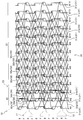
- FIG. 1 It is a top view which shows typically the water-stopping slide fastener which concerns on embodiment of this invention. It is a structure diagram which shows the knitting structure of the braided fastener stringer used for the water-stopping slide fastener shown in FIG. It is a structure chart of each thread forming a braided fastener stringer.
- the present invention is not limited to the embodiments described below, and various changes can be made as long as the present invention has substantially the same configuration as the present invention and exhibits the same effects. It is possible.
- the thicknesses of the various knitting yarns and the weft insertion yarns forming the fastener tape of the braided fastener stringer are not particularly limited, and the thickness can be changed as needed.
- FIG. 1 is a plan view schematically showing the water-stopping slide fastener of the present embodiment.
- FIG. 2 is a structure diagram showing the knitting structure of the braided fastener stringer of the present embodiment
- FIG. 3 is a structure diagram of each thread forming the braided fastener stringer.
- the weft insertion is drawn by bending so as not to overlap with the points in the organizational chart for easy viewing.
- the front-rear direction refers to the tape length direction of the fastener tape parallel to the sliding direction of the slider, and in particular, the direction in which the slider slides so as to mesh the left and right element rows (closing direction).
- the front is defined as the front
- the sliding direction is defined as the rear so as to separate the left and right element rows.
- the left-right direction refers to the tape width direction of the fastener tape, for example, a direction orthogonal to the sliding direction of the slider and parallel to the front surface (upper surface) and the back surface (lower surface) of the fastener tape.
- the vertical direction refers to a direction orthogonal to the front-rear direction and the left-right direction, for example, a tape front-back direction orthogonal to the front surface and the back surface of the fastener tape.
- the direction on the side where the slider pull is arranged with respect to the fastener tape is upward, and the direction on the opposite side is downward.
- the direction parallel to the length direction of the fastener tape is the wale direction
- the direction orthogonal to the wale direction is the course direction.
- the slide fastener 1 of the present embodiment shown in FIG. 1 has a pair of left and right braided fastener stringers 10 and sliders 40 attached to the left and right element rows 11 provided on the braided fastener stringer 10.
- the element rows 11 of the left and right braided fastener stringers 10 are meshed with each other over the entire length direction to form a fastener chain.
- the fastener tape 20 of the braided fastener stringer 10 is a tape surface (first tape surface) which is a surface on the side exposed to the outside and a tape back surface (first tape surface) arranged on the opposite side. It has 2 tape surfaces).
- the element row 11 is provided on the back side of the tape of the fastener tape 20. Therefore, the slide fastener 1 of the present embodiment is formed as a so-called back-use type slide fastener in which the element row 11 is hidden behind the fastener tape 20 and becomes invisible or difficult to see when the slide fastener 1 is closed. ..
- the slider 40 of the present embodiment is formed substantially in the same manner as the slider used in the conventional back-use type slide fastener. Therefore, in the present embodiment, detailed description of the slider 40 will be omitted.
- Each of the left and right braided fastener stringers 10 has a fastener tape 20 having a tape main body portion 21 and an element mounting portion 22, and a plurality of coil-shaped continuous fastener elements 12 woven into the element mounting portion 22.
- the element row 11 is formed along the length direction of the fastener tape 20 by the plurality of fastener elements 12 woven into the fastener tape 20.
- a film member made of synthetic resin (not shown) is adhered to the tape surface of the fastener tape 20 by adhesion. Further, the fastener tape 20 including the film member is subjected to a water repellent treatment. As a result, the slide fastener 1 is water-stopped.
- the braided fastener stringer of the present invention may be formed as a normal type braided fastener stringer that does not have water stopping property by not applying the water repellent treatment. Further, the braided fastener stringer of the present invention may be formed without attaching a film member to the fastener tape 20.
- Each braided slide fastener 1 of the present embodiment is knitted by a warp knitting machine (for example, a double Russell knitting machine) having two rows of needle beds composed of a back row B and a front row F.
- the back row B and the front row F of the needle bed are also referred to as a back needle row and a front needle row, respectively.
- the fastener element 12 of the present embodiment is formed of a single synthetic resin monofilament, and has substantially the same form as a general fastener element used in a conventional braided fastener stringer.
- each fastener element 12 of the present embodiment has a meshing head, an upper leg portion extending in the tape width direction from the upper end portion of the meshing head, and a lower leg extending in the tape width direction from the lower end portion of the meshing head. It has a portion and a connecting portion (also referred to as an inversion portion) that connects the fastener elements 12 adjacent to each other in the tape length direction.
- the fastener element 12 projects the meshing head outward from the tape side edge on the element mounting portion 22 side of the fastener tape 20, and the upper leg portion and the lower leg portion become the element mounting portion 22. It is woven and fixed.
- the tape side edge on the element mounting portion 22 side of the fastener tape 20 is the tape inner edge
- the tape side edge on the opposite side is the tape outer edge.
- the tape inner edge of the fastener tape 20 is the opposite side edge of the braided fastener stringer 10 of the meshing partner facing the fastener tape 20.
- the fastener tape 20 of the present embodiment has a warp knitting structure knitted by the warp knitting machine described above.
- the fastener tape 20 has 14 rows of wales from the first wales W1 to the 14th wales W14 from the inner edge of the tape to the outer edge of the tape.
- the wales arranged closest to the inner edge of the tape of the fastener tape 20 are the first wales W1
- the second wales W2 to the 14th wales W14 are in the course direction from the first wales W1 toward the outer edge of the tape. It is formed in order.
- the number of rows of wales formed on the fastener tape 20 is not particularly limited, and the number of rows of wales can be increased or decreased depending on the use of the braided fastener stringer 10.
- the fastener tape 20 has a tape main body portion 21 and an element mounting portion 22 extending in the tape width direction from the inner side edge portion of the tape main body portion 21 toward the meshing partner side.
- the element mounting portion 22 of the fastener tape 20 is formed by three rows of wales, the first wales W1 to the third wales W3.
- the tape body 21 is formed by 11 rows of wales from the 4th wales W4 to the 14th wales W14.
- the selvage portion of the fastener tape 20 is formed by three rows of 12th wales W12 to 14th wales W14 arranged near the outer edge of the tape of the tape main body portion 21.
- the ground structure of the fastener tape 20 (that is, the ground structure of the tape main body portion 21 and the ground structure of the element mounting portion 22) is knitted in a single structure by the back row B of the warp knitting machine.
- the fixing chain knitting yarn 34 which will be described later, is arranged on the element mounting portion 22 and is entwined with the ground structure of the element mounting portion 22 in a single structure by the front row F of the warp knitting machine.
- the ground structure of the fastener tape 20 is knitted using three types of yarns: a chain knitting yarn 31, a single satin knitting yarn 32, and a weft insertion yarn 33.
- the chain knitting yarn 31 is knitted with a knitting structure of (0-1 / 1-1 / 1-0 / 0-0) and is arranged on each of the first wales W1 to the 14th wales W14.
- the chain knitting yarn 31 of each wale has a needle loop of an opening formed in each course and a sinker loop connecting needle loops adjacent to each other in the wale direction. They are connected by sinker loops and formed in a chain along the wale direction.
- the chain knitting yarn 31a arranged on the first wale W1 on the inner edge of the tape is the most among the chain knitting yarns 31 arranged on the first wale W1 to the 14th wale W14. Thick threads are arranged.
- the chain knitting yarn 31a arranged on the first wale W1 is the other chain knitting yarn 31b arranged on the element mounting portion 22 (in the case of the present embodiment, the second and third wale W2, It has a thickness of 1.5 times or more and 4 times or less, preferably 3 times the thickness of the chain knitting yarn 31b) arranged in W3.
- the chain knitting yarn 31a arranged on the first wale W1 has a thickness of 310 decitex
- the chain knitting yarn 31b arranged on the second and third wales W2 and W3 is 110. It has the thickness of decitex.
- the element attachment portion 22 and the tape body portion 21 of the fastener tape 20 do not have to be thickened without thickening the chain knitting yarn 31b arranged on the second and third wales W2 and W3 that actually fix the fastener element 12.
- the dimension (width dimension) in the tape width direction from the boundary portion 23 to the inner edge of the tape of the element mounting portion 22 can be easily secured to be large.
- the distance between the left and right fastener tapes 20 in the closed state of the slide fastener 1 can be reduced to 0.35 mm or less, preferably 0.30 mm or less.
- the chain knitting yarns 31c arranged on the 12th wales W12 to the 14th wales W14 forming the ears of the tape main body 21 are the chain knitting yarns arranged on other than the ears of the tape main body 21. It is formed thicker than 31d (in the case of the present embodiment, the chain knitting yarn 31d arranged on the fourth wale W4 to the eleventh wale W11).
- the chain knitting yarns 31d arranged on the 4th wales W4 to the 11th wales W11 have a thickness of 110 decitex
- the chain knitting yarns arranged on the 12th wales W12 to the 14th wales W14 have a thickness of 220 decitex.
- the single satin knitting yarn 32 is knitted with a knitting structure of (1-0 / 2-2 / 3-4 / 2-2). Each single satin knitting yarn 32 is arranged over four adjacent rows of wales. Further, the single satin knitting yarn 32 has closed needle loops alternately formed on two rows of wales on the left and right ends of the four rows, and sinker loops connecting the needle loops of the wales on both ends. ..
- the needle loops of the single satin knitting yarn 32 are alternately formed in the wales direction on two rows of wales arranged at positions three rows apart from each other in the course direction. Therefore, between the two wales on which the needle loop of the single satin knitting yarn 32 is formed, two wales on which the needle loop is not formed by the single satin knitting yarn 32 are arranged.
- the sinker loop of the single satin knitting yarn 32 connects the needle loop formed on one wale and the needle loop formed on the other wale. Therefore, the sinker loops of the single satin knitting yarn 32 are arranged long over the distance between the three stitches so as to straddle the two wales between the courses. In the present embodiment, the sinker loop of the single satin knitting yarn 32 appears on the back surface of the tape of the fastener tape 20 (the tape surface on the side where the film member is not attached).
- 10 single satin knitting yarns 32 are arranged so that needle loops of the single satin knitting yarns 32 are formed on each of the first wales W1 to the thirteenth wales W13. Therefore, the needle loop forming each of the first wales W1 to the thirteenth wales W13 includes both the needle loop of the chain knitting yarn 31 and the needle loop of the single satin knitting yarn 32. .. In particular, in each of the fourth wales W4 to the thirteenth wales W13 forming the tape main body 21, the needle loop of the chain knitting yarn 31 and the needle loop of the single satin knitting yarn 32 in all the stitches formed in the back row B. Both are formed. As a result, the fastener tape 20 can stably have an appropriate tape strength.
- the 14th wale W14 formed on the outermost edge of the fastener tape 20 does not have a needle loop of the single satin knitting yarn 32, but only a needle loop of the chain knitting yarn 31.
- the outer edge of the fastener tape 20 can be formed thinly, so that when the braided fastener stringer 10 is viewed, the fastener tape 20 tends to give a thin or light impression. Further, when the fastener tape 20 is touched with a finger, the fastener tape 20 can be easily felt thin. Further, the flexibility of the fastener tape 20 can be improved by reducing the number of needle loops formed on the 14th wales W14 to be smaller than the number of other wales of the tape body 21.
- the wales of the element mounting portion 22 (first wales W1, second wales W2, or third wales W3) and the wales of the tape body portion 21 (fourth wales W4, fifth wales W4) It has a first single satin knitting yarn 32a that alternately forms needle loops on W5 or a sixth wale W6), and a second single satin knitting yarn 32b that forms needle loops only on the wales of the tape body 21.
- the sinker loop of the first single satin knitting yarn 32a is arranged across the boundary portion 23 of the tape main body portion 21 and the element mounting portion 22.
- the boundary portion 23 between the tape main body portion 21 and the element mounting portion 22 is located between the third wale W3 and the fourth wale W4. That is, in the present embodiment, the sinker loop of the three first single satin knitting yarns 32a and the two weft insertion yarns 33 form the boundary portion 23 between the tape main body portion 21 and the element mounting portion 22 between the courses. It is arranged to cross. Further, in this case, the sinker loop of the first single satin knitting yarn 32a and the two weft insertion yarns 33 intersect each course as described later. As a result, the tape strength of the boundary portion 23 between the tape main body portion 21 and the element mounting portion 22 and the tape strength of the portion in the vicinity of the boundary portion 23 are increased.
- the first single satin knitting yarn 32a that crosses the boundary portion 23 is formed thicker than the second single satin knitting yarn 32b.
- the first single satin knitting yarn 32a has a thickness of 1.1 times or more and 2.0 times or less, preferably 1.4 times or more and 1.6 times or less the thickness of the second single satin knitting yarn 32b.
- the first single satin knitting yarn 32a of the present embodiment has a thickness of 167 decitex
- the second single satin knitting yarn 32b has a thickness of 110 decitex.
- the portion where the tape strength is increased by the first single satin knitting yarn 32a is a portion where the flange portion of the slider 40 easily comes into contact with the slide fastener 1. Therefore, since the fastener tape 20 includes the first single satin knitting yarn 32a and has high tape strength as described above, the fastener tape 20 is damaged even if the sliding operation of the slider 40 is repeated. It can be difficult.
- a plurality of weft insertion threads 33 are inserted into the entire first wales W1 to 14th wales W14.
- Each weft insertion thread 33 is inserted in a zigzag shape over 3 wales.
- the weft insertion thread 33 of the present embodiment is inserted in a direction intersecting the sinker loop of the single satin knitting thread 32 between each course.
- the direction in which the weft insertion yarn 33 is folded back by the needle loop and the sinker loop of the single satin knitting yarn 32 are from the needle loop.
- the extending direction means that the direction of extension is deviated from the direction of the wales by one course.
- the weft insertion thread 33a arranged closest to the inner edge of the tape folded back by the first wale W1 is formed thinner than the other weft insertion threads 33 arranged on the fastener tape 20.
- the weft insertion yarn 33a can weaken the force (tension) that pulls the thick chain knitting yarn 31a arranged on the first wale W1 in the direction of approaching the tape main body portion 21. Therefore, it becomes easy to secure a large dimension in the tape width direction from the boundary portion 23 to the inner edge of the tape of the element mounting portion 22, and as a result, the gap formed between the left and right fastener tapes 20 can be reduced.
- the fixing chain knitting yarn 34 has a knitting structure of (0-0 / 0-1 / 1-1 / 1-0) by the front row F of the warp knitting machine, and the second wales of the element mounting portion 22. It is woven into W2 and the third wales W3. That is, the ground structure of the fastener tape 20 and the knitting portion of the chain knitting yarn 34 for fixing are knitted in separate single structures by the back row B and the front row F of the warp knitting machine. As a result, the flexibility of the fastener tape 20 can be increased, the weight of the braided fastener stringer 10 can be reduced, and the productivity can be improved.
- the upper leg portion and the lower leg portion of the fastener element 12 are inserted so as to be sandwiched between the ground structure of the element mounting portion 22 and the chain knitting yarn 34 for fixing.
- the sinker loop of the fixing chain knitting yarn 34 intersects and is entangled with the ground structure of the element mounting portion 22. More specifically, the sinker loop of the fixing chain knitting yarn 34 is entwined with at least one sinker loop of the chain knitting yarn 31 and the single satin knitting yarn 32 forming the ground structure.
- the fixing chain knitting yarn 34 is integrated with the ground structure of the element mounting portion 22.
- the fastener element 12 is woven into the element mounting portion 22 together with the fixing chain knitting yarn 34 and is firmly fixed. In this case, the fastener element 12 is fixed by the upper leg portion and the lower leg portion of the fastener element 12 being sandwiched between the fixing chain knitting yarn 34 and the ground structure of the element mounting portion 22.
- the fixing chain knitting yarn 34 is the first fixing chain knitting yarn 34a arranged on the second wale W2 near the inner edge of the tape and the tape main body portion 21 arranged on the third wale W3. It has a second fixing chain knitting yarn 34b.
- a yarn thicker than any of the yarns forming the ground structure of the fastener tape 20 is used.
- the first fixing chain knitting yarn 34a and the second fixing chain knitting yarn 34b are formed by aligning two yarns having a thickness of 220 decitex. As a result, the fastener element 12 can be firmly fixed to the element mounting portion 22 of the fastener tape 20 so that the position of the fastener element 12 does not shift.
- the second fixing chain knitting yarn 34b of the present embodiment includes two yarns having a thickness of 220 decitex when knitting the warp knitting for knitting the braided fastener stringer 10 as described later. It is formed to include auxiliary fibers to be removed. This auxiliary fiber is pulled out from the fastener tape 20 and disappears after the knitting process is completed. Therefore, in the manufactured braided fastener stringer 10, the second fixing chain knitting yarn 34b is formed by two yarns having a thickness of 220 decitex. Regarding the first fixing chain knitting yarn 34a of the present embodiment, the knitting process of the braided fastener stringer 10 is performed without including auxiliary fibers.
- the force for pressing the fastener element 12 with the second fixing chain knitting yarn 34b is applied.
- the force of pressing the fastener element 12 with the first fixing chain knitting yarn 34a can be weakened.
- the fastener tape 20 is compared with the case where the knitting process is performed without including the fibers to be removed in, for example, the first fixing chain knitting yarn 34a and the second fixing chain knitting yarn 34b. It becomes easy to allow the movement of each fastener element 12 woven into.
- the flexibility of the braided fastener stringer 10 can be increased more effectively, and the slidability of the slider 40 in the slide fastener 1 can be further improved.
- the fastener element 12 can be stably fixed to the element mounting portion 22.
- the meshing strength (horizontal pulling strength) of the fastener chain and the meshing strength (bending strength) when the fastener chain is bent in the front and back directions of the tape can be appropriately secured.
- a warp knitting process for knitting the braided fastener stringer 10 is performed using a warp knitting machine provided with two rows of needle beds composed of a back row B and a front row F.
- the needle loop of the fixing chain knitting yarn 34 is formed by the front row F, and the fixing chain knitting yarn is formed.
- the 34 sinker loops are entwined with the ground structure of the fastener tape 20.
- the fastener element 12 formed from the monofilament is inserted between the ground structure of the fastener tape 20 and the fixing chain knitting yarn 34.
- the ground structure of the fastener tape 20 is knitted using the chain knitting yarn 31, the single satin knitting yarn 32, and the weft insertion yarn 33 described above.
- the fixing chain knitting yarn 34 the first fixing chain knitting yarn 34a formed by aligning two yarns having a thickness of 220 decitex, and 2 having the aligned thickness of 220 decitex 2
- the fastener element 12 is knitted into the fastener tape 20 using a second fixing chain knitting yarn 34b containing a book yarn and auxiliary fibers.
- a braided fastener stringer 10 in which a plurality of fastener elements 12 are woven at regular intervals is knitted on the element mounting portion 22 of the fastener tape 20.
- the braided fastener stringer 10 obtained at this time has a warp knitting structure as shown in FIGS. 2 and 3.
- one braided fastener stringer 10 may be continuously manufactured, or two braided fastener stringers 10 are knitted in a state where the left and right element rows 11 are meshed with each other.
- Fastener chains may be manufactured continuously.
- the obtained braided fastener stringers 10 are combined in pairs to form a fastener chain, and the auxiliary fibers contained in the second fixing chain knitting yarn 34b are pulled out. Then, an adhesive is applied to the tape surfaces of the left and right fastener tapes 20 in the fastener chain. Subsequently, one film member made of synthetic resin is superposed and attached to the surface of the tape coated with the adhesive. As a result, the film member is adhered to the fastener tape 20.
- the type and material of the adhesive for adhering the film member are not particularly limited.
- the method and means for attaching the film member to the fastener tape 20 are not particularly limited, and the film member may be attached to the fastener tape 20 by a method or means other than adhesion.
- the fastener chain to which the film member is attached is subjected to a water repellent treatment. Then, by cutting the film member along the length direction of the fastener chain at the boundary between the left and right fastener tapes 20, a fastener chain having water stopping property is manufactured. Further, by attaching the slider 40 to the left and right element rows 11 of the manufactured fastener chain, the slide fastener 1 having the water-stopping property shown in FIG. 1 is manufactured.
- the ground structure of the left and right fastener tapes 20 is knitted using a single satin knitting yarn 32 that forms a sinker loop long between each course. .. Therefore, the left and right braided fastener stringers 10 have high flexibility.
- the sinker loop of the single satin knitting yarn 32 is fastened on the back surface of the tape on the side where the fastener element 12 of the fastener tape 20 is knitted (in other words, the tape surface on the side where the film member is not attached). It appears longer in the direction inclined with respect to the tape width direction of the tape 20. As a result, the back surface of the fastener tape 20 is formed on a smooth surface that gives a good touch. Further, the fastener tape 20 can have a good texture due to the single satin knitting yarn 32.
- the tape strength of the boundary portion 23 between the tape main body portion 21 and the element mounting portion 22 of the fastener tape 20 and the vicinity thereof is three thick first singles. It is enhanced by a satin knitting yarn 32a and two weft insertion yarns 33. As a result, damage caused by rubbing of the fastener tape 20 with the slider 40 or the like can be suppressed.
- the slide fastener 1 of the present embodiment which is soft, soft to the touch, and has appropriate tape strength, is suitably used for clothing that comes into direct contact with the skin, clothing that is made of a thin cloth, and the like. ..
- the gap between the left and right fastener tapes 20 formed when the slide fastener 1 is closed is 0. It can be reduced to 35 mm or less, preferably 0.30 mm or less. As a result, the meshed left and right element rows 11 can be made difficult to see from the tape surface side of the fastener tape 20 through the gap between the left and right fastener tapes 20.
- the length of the film member that adheres to the fastener tape 20 extends from the inner edge of the fastener tape 20 toward the meshing head side in the tape width direction. Can be shortened. This makes it difficult to cause appearance defects such as white lines observed between the left and right fastener tapes in a conventional water-stopping slide fastener. As a result, the appearance quality of the water-stopping slide fastener 1 can be improved. Further, by reducing the gap between the left and right fastener tapes 20, the slide fastener 1 can stably provide good water stopping property.
- the braided fastener stringer 10 of the above-described embodiment is used for the back-use type slide fastener 1, but the braided fastener stringer of the present invention is a normal type slide fastener in which the element row is exposed to the outside. Can be applied in the same way.
- auxiliary fibers are previously included only in the second fixing chain knitting yarn 34b of the fixing chain knitting yarn 34, and the auxiliary fibers are contained therein. Auxiliary fibers are removed after knitting.
- the auxiliary fiber may be contained only in the first fixing chain knitting yarn 34a of the fixing chain knitting yarn 34, or the first fixing may be included. Both the chain knitting yarn 34a and the second fixing chain knitting yarn 34b may contain auxiliary fibers.
- the braided fastener stringer 10 may be knitted without including auxiliary fibers. In this case, for example, a water-soluble fiber is used as the auxiliary fiber, and pulling out the fiber after the knitting process includes dissolving the water-soluble fiber in a liquid.
Landscapes
- Engineering & Computer Science (AREA)
- Textile Engineering (AREA)
- Slide Fasteners (AREA)
Priority Applications (6)
| Application Number | Priority Date | Filing Date | Title |
|---|---|---|---|
| JP2021552031A JP7191499B2 (ja) | 2019-10-16 | 2019-10-16 | ファスナーチェーン、及びファスナーチェーンの製造方法 |
| EP19948957.6A EP4046524B1 (en) | 2019-10-16 | 2019-10-16 | Knitted fastener stringer, fastener chain, and method for manufacturing knitted fastener stringer |
| CN201980100651.9A CN114554902B (zh) | 2019-10-16 | 2019-10-16 | 编织拉链牙链带、拉链链条及编织拉链牙链带的制造方法 |
| US17/765,078 US12016435B2 (en) | 2019-10-16 | 2019-10-16 | Knitted fastener stringer, fastener chain, and method for manufacturing knitted fastener stringer |
| PCT/JP2019/040625 WO2021074992A1 (ja) | 2019-10-16 | 2019-10-16 | 編込みファスナーストリンガー、ファスナーチェーン、及び編込みファスナーストリンガーの製造方法 |
| TW109113132A TWI742620B (zh) | 2019-10-16 | 2020-04-20 | 編織拉鏈牙鏈帶、拉鏈鏈條以及編織拉鏈牙鏈帶的製造方法 |
Applications Claiming Priority (1)
| Application Number | Priority Date | Filing Date | Title |
|---|---|---|---|
| PCT/JP2019/040625 WO2021074992A1 (ja) | 2019-10-16 | 2019-10-16 | 編込みファスナーストリンガー、ファスナーチェーン、及び編込みファスナーストリンガーの製造方法 |
Publications (1)
| Publication Number | Publication Date |
|---|---|
| WO2021074992A1 true WO2021074992A1 (ja) | 2021-04-22 |
Family
ID=75537518
Family Applications (1)
| Application Number | Title | Priority Date | Filing Date |
|---|---|---|---|
| PCT/JP2019/040625 Ceased WO2021074992A1 (ja) | 2019-10-16 | 2019-10-16 | 編込みファスナーストリンガー、ファスナーチェーン、及び編込みファスナーストリンガーの製造方法 |
Country Status (6)
| Country | Link |
|---|---|
| US (1) | US12016435B2 (https=) |
| EP (1) | EP4046524B1 (https=) |
| JP (1) | JP7191499B2 (https=) |
| CN (1) | CN114554902B (https=) |
| TW (1) | TWI742620B (https=) |
| WO (1) | WO2021074992A1 (https=) |
Citations (7)
| Publication number | Priority date | Publication date | Assignee | Title |
|---|---|---|---|---|
| JPS546940B2 (https=) * | 1971-08-18 | 1979-04-02 | ||
| JP2000312604A (ja) * | 1999-04-30 | 2000-11-14 | Ykk Corp | 防水性を有するスライドファスナーおよびその製造方法 |
| JP2004261246A (ja) * | 2003-02-28 | 2004-09-24 | Ykk Corp | 吸水性ファスナー |
| JP2005230040A (ja) * | 2004-02-17 | 2005-09-02 | Ykk Corp | 編込みスライドファスナー |
| WO2011077568A1 (ja) | 2009-12-25 | 2011-06-30 | Ykk株式会社 | 編込みスライドファスナー |
| WO2011121702A1 (ja) * | 2010-03-29 | 2011-10-06 | Ykk株式会社 | ファスナーテープ及びファスナーストリンガー |
| WO2013011559A1 (ja) | 2011-07-19 | 2013-01-24 | Ykk株式会社 | 編込みファスナーストリンガー |
Family Cites Families (14)
| Publication number | Priority date | Publication date | Assignee | Title |
|---|---|---|---|---|
| JPS5952909U (ja) * | 1982-09-29 | 1984-04-07 | ワイケイケイ株式会社 | スライドフアスナ− |
| JP3396335B2 (ja) | 1995-05-12 | 2003-04-14 | ワイケイケイ株式会社 | 編込みスライドファスナー |
| JP3526390B2 (ja) * | 1997-05-02 | 2004-05-10 | Ykk株式会社 | 反射性スライドファスナー用経編テープ |
| JP2002360315A (ja) * | 2001-06-07 | 2002-12-17 | Ykk Corp | 編込みスライドファスナー |
| CN100551291C (zh) * | 2003-06-02 | 2009-10-21 | Ykk株式会社 | 针织、机织的隐形拉链 |
| JP4450758B2 (ja) * | 2005-03-25 | 2010-04-14 | Ykk株式会社 | 編込みスライドファスナー |
| JP4731378B2 (ja) | 2006-03-31 | 2011-07-20 | Ykk株式会社 | ファスナーテープ及びファスナーストリンガー |
| US7739887B2 (en) * | 2007-06-08 | 2010-06-22 | Da-An Hung | Knitted band for zipper |
| CN101938924B (zh) * | 2008-04-15 | 2011-12-21 | Ykk株式会社 | 编织拉链用拉链牙链带 |
| WO2011007411A1 (ja) * | 2009-07-13 | 2011-01-20 | Ykk株式会社 | 編込みファスナーストリンガー |
| JP5615929B2 (ja) | 2010-09-29 | 2014-10-29 | Ykk株式会社 | 編物製テープを備えたファスナーストリンガー |
| JP5459273B2 (ja) * | 2011-06-30 | 2014-04-02 | 株式会社デンソー | 雨滴検出装置 |
| JPWO2013011559A1 (ja) * | 2011-07-19 | 2015-02-23 | Ykk株式会社 | 編込みファスナーストリンガー |
| EP2769638B1 (en) * | 2011-10-19 | 2017-06-28 | YKK Corporation | Slide fastener and hidden slide fastener |
-
2019
- 2019-10-16 JP JP2021552031A patent/JP7191499B2/ja active Active
- 2019-10-16 US US17/765,078 patent/US12016435B2/en active Active
- 2019-10-16 WO PCT/JP2019/040625 patent/WO2021074992A1/ja not_active Ceased
- 2019-10-16 EP EP19948957.6A patent/EP4046524B1/en active Active
- 2019-10-16 CN CN201980100651.9A patent/CN114554902B/zh active Active
-
2020
- 2020-04-20 TW TW109113132A patent/TWI742620B/zh active
Patent Citations (7)
| Publication number | Priority date | Publication date | Assignee | Title |
|---|---|---|---|---|
| JPS546940B2 (https=) * | 1971-08-18 | 1979-04-02 | ||
| JP2000312604A (ja) * | 1999-04-30 | 2000-11-14 | Ykk Corp | 防水性を有するスライドファスナーおよびその製造方法 |
| JP2004261246A (ja) * | 2003-02-28 | 2004-09-24 | Ykk Corp | 吸水性ファスナー |
| JP2005230040A (ja) * | 2004-02-17 | 2005-09-02 | Ykk Corp | 編込みスライドファスナー |
| WO2011077568A1 (ja) | 2009-12-25 | 2011-06-30 | Ykk株式会社 | 編込みスライドファスナー |
| WO2011121702A1 (ja) * | 2010-03-29 | 2011-10-06 | Ykk株式会社 | ファスナーテープ及びファスナーストリンガー |
| WO2013011559A1 (ja) | 2011-07-19 | 2013-01-24 | Ykk株式会社 | 編込みファスナーストリンガー |
Non-Patent Citations (1)
| Title |
|---|
| See also references of EP4046524A4 |
Also Published As
| Publication number | Publication date |
|---|---|
| EP4046524A4 (en) | 2022-10-12 |
| CN114554902B (zh) | 2024-03-15 |
| JPWO2021074992A1 (https=) | 2021-04-22 |
| CN114554902A (zh) | 2022-05-27 |
| TWI742620B (zh) | 2021-10-11 |
| TW202116209A (zh) | 2021-05-01 |
| US20220386747A1 (en) | 2022-12-08 |
| EP4046524B1 (en) | 2024-10-30 |
| JP7191499B2 (ja) | 2022-12-19 |
| EP4046524A1 (en) | 2022-08-24 |
| US12016435B2 (en) | 2024-06-25 |
Similar Documents
| Publication | Publication Date | Title |
|---|---|---|
| JP4387124B2 (ja) | スライドファスナー用テープと同テープを使ったスライドファスナー用ストリンガー | |
| TWI389652B (zh) | Invisible zipper with the chain | |
| CN100551291C (zh) | 针织、机织的隐形拉链 | |
| JP3895272B2 (ja) | 繊維製面ファスナー | |
| JP3552947B2 (ja) | 編込みスライドファスナー | |
| JP3930440B2 (ja) | スライドファスナー用経編テープ | |
| TWI250860B (en) | Knitted slide fastener | |
| TWI403284B (zh) | Woven into the chain | |
| CN109475207B (zh) | 编织拉链链牙带 | |
| CN103687510B (zh) | 编入拉链条 | |
| JP4731378B2 (ja) | ファスナーテープ及びファスナーストリンガー | |
| CN103082590B (zh) | 编织拉链牙链带 | |
| KR100705517B1 (ko) | 편입 슬라이드 파스너 | |
| TWI410225B (zh) | A zipper chain, and a method of manufacturing a fastener tape | |
| JP7191499B2 (ja) | ファスナーチェーン、及びファスナーチェーンの製造方法 | |
| CN102686124B (zh) | 编织拉链 | |
| JP7496003B2 (ja) | ファスナーストリンガー及びファスナーストリンガーの製造方法 | |
| JP7602259B2 (ja) | 編レース | |
| WO2009128140A1 (ja) | 編込みスライドファスナー用ファスナーストリンガー | |
| CN107296337A (zh) | 链带和拉链 | |
| JP2022030892A (ja) | 編込みファスナーストリンガー及びカバー部材 | |
| KR100761572B1 (ko) | 편직입 숨김 슬라이드 고정구 | |
| JPWO2013011559A1 (ja) | 編込みファスナーストリンガー | |
| HK1106403B (en) | Fastener tape and fastener stringer |
Legal Events
| Date | Code | Title | Description |
|---|---|---|---|
| 121 | Ep: the epo has been informed by wipo that ep was designated in this application |
Ref document number: 19948957 Country of ref document: EP Kind code of ref document: A1 |
|
| ENP | Entry into the national phase |
Ref document number: 2021552031 Country of ref document: JP Kind code of ref document: A |
|
| NENP | Non-entry into the national phase |
Ref country code: DE |
|
| ENP | Entry into the national phase |
Ref document number: 2019948957 Country of ref document: EP Effective date: 20220516 |