WO2021065606A1 - 補強スリーブ、光ファイバ接続部の補強構造及び補強方法 - Google Patents
補強スリーブ、光ファイバ接続部の補強構造及び補強方法 Download PDFInfo
- Publication number
- WO2021065606A1 WO2021065606A1 PCT/JP2020/035748 JP2020035748W WO2021065606A1 WO 2021065606 A1 WO2021065606 A1 WO 2021065606A1 JP 2020035748 W JP2020035748 W JP 2020035748W WO 2021065606 A1 WO2021065606 A1 WO 2021065606A1
- Authority
- WO
- WIPO (PCT)
- Prior art keywords
- optical fiber
- fiber core
- heat
- tensile strength
- reinforcing
- Prior art date
- Legal status (The legal status is an assumption and is not a legal conclusion. Google has not performed a legal analysis and makes no representation as to the accuracy of the status listed.)
- Ceased
Links
Images


Classifications
-
- G—PHYSICS
- G02—OPTICS
- G02B—OPTICAL ELEMENTS, SYSTEMS OR APPARATUS
- G02B6/00—Light guides; Structural details of arrangements comprising light guides and other optical elements, e.g. couplings
- G02B6/24—Coupling light guides
- G02B6/255—Splicing of light guides, e.g. by fusion or bonding
- G02B6/2558—Reinforcement of splice joint
-
- G—PHYSICS
- G02—OPTICS
- G02B—OPTICAL ELEMENTS, SYSTEMS OR APPARATUS
- G02B6/00—Light guides; Structural details of arrangements comprising light guides and other optical elements, e.g. couplings
- G02B6/24—Coupling light guides
- G02B6/255—Splicing of light guides, e.g. by fusion or bonding
- G02B6/2553—Splicing machines, e.g. optical fibre fusion splicer
-
- G—PHYSICS
- G02—OPTICS
- G02B—OPTICAL ELEMENTS, SYSTEMS OR APPARATUS
- G02B6/00—Light guides; Structural details of arrangements comprising light guides and other optical elements, e.g. couplings
- G02B6/24—Coupling light guides
- G02B6/255—Splicing of light guides, e.g. by fusion or bonding
- G02B6/2555—Alignment or adjustment devices for aligning prior to splicing
-
- G—PHYSICS
- G02—OPTICS
- G02B—OPTICAL ELEMENTS, SYSTEMS OR APPARATUS
- G02B6/00—Light guides; Structural details of arrangements comprising light guides and other optical elements, e.g. couplings
- G02B6/44—Mechanical structures for providing tensile strength and external protection for fibres, e.g. optical transmission cables
- G02B6/4439—Auxiliary devices
- G02B6/4471—Terminating devices ; Cable clamps
- G02B6/4476—Terminating devices ; Cable clamps with heat-shrinkable elements
Definitions
- the present invention relates to a reinforcing sleeve, a reinforcing structure of an optical fiber connection portion using the reinforcing sleeve, and a reinforcing method.
- a reinforcing sleeve is provided at the fusion-bonded connection portion to reinforce the fiber.
- an optical fiber tape core wire in which a plurality of optical fiber core wires are arranged and bonded in parallel has been used for storage in a cable and simplification of work. It is used. Further, there is an optical fiber tape core wire in which parallel optical fibers are fixed with a resin over the entire length, and an optical fiber ribbon wire in which a plurality of parallel optical fiber core wires are intermittently bonded in the longitudinal direction. Intermittent bonding of optical fiber cores has features such as improvement of concentration density, reduction of transmission loss due to bending, and facilitation of monocentricity.
- the optical fiber tape core wire and the optical fiber ribbon wire are combined to simply form an optical fiber tape core wire or the like.
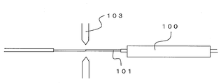
- FIG. 5A to 5C are diagrams showing a process of reinforcing a connecting portion such as an optical fiber tape core wire by using a reinforcing sleeve.
- the optical fiber core wires 101 arranged to face each other are butted against each other, and the optical fiber core wires 101 are fused by discharge from the electrode 103.
- the reinforcing sleeve 100 is retracted to one of the optical fiber core wires 101.
- the reinforcing sleeve 100 is moved to the connection portion between the optical fiber core wires 101 (arrow C in the figure).
- the reinforcing sleeve 100 is heated and contracted to integrate the reinforcing sleeve 100 and the plurality of optical fiber core wires 101.
- the connection portion between the plurality of optical fiber core wires 101 is reinforced.
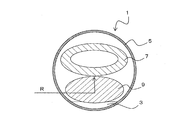
- FIG. 6A is a cross-sectional view of the state of FIG. 5B.
- the reinforcing sleeve 100 is configured by inserting the heat melting member 107 and the tensile strength body 109 into the heat shrink tube 105.
- the hot-melting member 107 has a tubular shape, and the connecting portion of the parallel optical fiber core wires 101 is provided so as to penetrate the hot-melting member 107.
- the outer cover of the optical fiber core wire 101 penetrating the hot melting member 107 is removed before connection.
- FIG. 6B is an ideal conceptual diagram showing the structure when the reinforcing sleeve 100 is heated.
- the heat shrink tube 105 shrinks by heating.
- the heat-melting member 107 is softened by heat, fills a gap inside the heat-shrinkable tube 105 after shrinkage, and is integrated with a plurality of optical fiber core wires 101 and a tensile strength body 109.
- a flat surface is usually formed on the upper surface of the tensile strength body 109 (on the side of the optical fiber core wire 101). It is desired that the plurality of optical fiber core wires 101 are aligned along the flat surface of the upper surface of the tensile strength body 109 and integrated with the tensile strength body 109 and the hot melting member 107.
- the heat-melting member 107 receives a force from the surroundings (arrow D in the figure), and the plurality of optical fiber core wires 101 exert lateral pressure. receive.
- the optical fiber core wires 101 are arranged straight along the flat portion on the upper surface of the tensile strength body 109, but the arrangement of the optical fiber core wires 101 is particularly due to the lateral pressure from the width direction. Disturbed. For example, some optical fiber core wires 101 move away from the tensile strength body 109 and tend to gather near the center.
- Such a tendency becomes stronger as the distance (pitch) between the optical fiber cores 101 becomes narrower and as the number of optical fiber cores increases. Further, as the diameter of the optical fiber wire becomes smaller, the rigidity becomes smaller, so that this tendency becomes stronger. Further, in the case of an intermittently bonded optical fiber ribbon wire in which a plurality of optical fiber core wires are intermittently bonded to each other in the longitudinal direction, this tendency becomes even stronger.
- the arrangement of the optical fiber core wires 101 is disturbed in this way, the transmission loss of some of the optical fiber core wires 101 may increase. Therefore, when the heat-shrinkable tube 105 is contracted, it is desired that the arrangement of the optical fiber core wires 101 is not disturbed and is always integrated in a constant form.
- the present invention has been made in view of such a problem, and an object of the present invention is to provide a reinforcing sleeve or the like capable of efficiently reinforcing a connecting portion such as an optical fiber tape core wire.
- the first invention is a reinforcing sleeve that collectively reinforces the connection portion of a plurality of parallel optical fiber core wires, and is inserted into a heat-shrinkable tube and the heat-shrinkable tube.
- a reinforcement provided with a heat-melting member and a tensile strength body, wherein the surface of the tensile strength body on the heat-melting member side is formed by a convex curved surface in a cross section perpendicular to the longitudinal direction of the tensile strength body. It is a sleeve.
- the radius of curvature of the convex curved surface is larger than the radius of curvature of the inner surface of the heat-shrinkable tube.
- the cross-sectional shape of the tensile strength body is elliptical.
- Protrusions may be formed at both ends of the tensile strength body.
- the surface of the tensile strength body on the side where the optical fiber core wire is arranged is formed by an arcuate convex curved surface, so that the optical fibers are arranged in parallel.
- the core wire receives lateral pressure from both sides in the width direction, a force component in the direction in which each optical fiber core wire is pressed against the tensile strength body acts. Therefore, it is possible to suppress the lifting of each optical fiber core wire from the tensile strength body and the disorder of the arrangement, and to arrange each optical fiber core wire more stably along the shape of the upper surface of the tensile strength body. Can be done. As a result, it is possible to suppress an increase in transmission loss and variation in the transmission loss of each optical fiber core wire.
- the arrangement of the optical fiber core wires can be arranged along the gentle curved surface.
- the width of the tensile strength body with respect to the parallel direction of the optical fiber core wire can be secured, and the increase in the cross-sectional area occupied by the tensile strength body in the heat-shrinkable tube is suppressed. can do.
- the amount of the heat-melting member used to press the optical fiber core wire against the tensile strength body can be kept constant, and a stable contracted state can be realized.
- the second invention is a reinforcing structure of an optical fiber connection portion using the reinforcing sleeve according to the first invention, in which a plurality of optical fiber core wires are intermittently bonded to each other in the longitudinal direction.
- the optical fiber connecting portion is covered with the heat melting member, and the plurality of optical fiber core wires constituting the optical fiber ribbon wire are arranged along the curved surface of the tensile strength body. It is a reinforced structure of.
- the number of cores of the plurality of optical fiber core wires constituting the optical fiber ribbon wire is 12 or more.
- the pitch between the plurality of optical fiber core wires is 200 ⁇ m or less.
- the outer diameter of the glass fiber of the optical fiber core wire is 110 ⁇ m or less.
- the outer diameter of the optical fiber core wire is 200 ⁇ m or less.
- the plurality of optical fiber core wires constituting the optical fiber ribbon wire are arranged along the curved surface of the tensile strength body, it is possible to suppress the variation in transmission loss for each optical fiber core wire. ..
- the above effect is remarkable when the number of cores of the plurality of optical fiber cores constituting the optical fiber ribbon wire is 12 or more. Further, the above effect is remarkable when the pitch between the optical fiber core wires is 200 ⁇ m or less. Further, the above effect is remarkable when the outer diameter of the glass fiber of the optical fiber core wire is 110 ⁇ m or less. Further, the above effect is remarkable when the outer diameter of the optical fiber core wire is 200 ⁇ m or less.
- a third invention is a method for reinforcing an optical fiber connection portion using a reinforcing sleeve according to the first invention, wherein a plurality of optical fiber core wires are intermittently bonded to each other in the longitudinal direction.
- the reinforcing sleeve is moved so as to cover the connection portion between the optical fiber ribbon wires, the heat-shrinkable tube and the heat-melting member are heated, the heat-shrinkable tube is contracted, and the heat-melting is performed.
- the member is melted, the plurality of optical fiber core wires are cooled in a state of being arranged along the curved surface of the tensile strength body, and the tensile strength body and the connection portion of the plurality of optical fiber core wires are integrated. This is a characteristic method for reinforcing an optical fiber connection portion.
- the third invention it is possible to obtain a reinforcing structure of an optical fiber connection portion having efficient and stable transmission performance.
- the pitch between the optical fiber cores is 200 ⁇ m or less.
- FIG. 1A is a cross-sectional view taken along the line AA of FIG. 1A. It is a figure which shows the reinforcement process of the connection part between the optical fiber core wires 11 using the reinforcement sleeve 1, and is the cross-sectional view before shrinkage of the reinforcement sleeve 1. It is a figure which shows the reinforcement process of the connection part between the optical fiber core wires 11 using the reinforcement sleeve 1, and is the cross-sectional view after shrinkage of the reinforcement sleeve 1. The figure which shows the optical fiber ribbon wire 12. The figure which shows the state in which the optical fiber ribbon wires 12 are butted against each other.
- the figure which shows the connection process of the optical fiber core wire 101 using a reinforcing sleeve 100 It is a figure which shows the reinforcement process of the connection part between the optical fiber core wires 101 using the reinforcement sleeve 100, and is the cross-sectional view before shrinkage of the reinforcement sleeve 100. It is a figure which shows the reinforcement process of the connection part between the optical fiber core wires 101 using the reinforcement sleeve 100, and is the ideal cross-sectional conceptual diagram after shrinkage of a reinforcement sleeve 100. It is a figure which shows the reinforcement process of the connection part between the optical fiber core wires 101 using the reinforcement sleeve 100, and is the actual cross-sectional conceptual diagram after shrinkage of the reinforcement sleeve 100.
- FIG. 1A is a side view of the reinforcing sleeve 1
- FIG. 1B is a cross-sectional view taken along the line AA of FIG. 1A.
- the reinforcing sleeve 1 is a member that collectively reinforces the connecting portions of a plurality of parallel optical fiber core wires, and is composed of a heat shrink tube 5, a heat melting member 7, a tensile strength body 9, and the like.
- the heat shrink tube 5 is a tubular member having a substantially circular cross section.
- the heat-shrinkable tube 5 is made of, for example, a polyethylene-based resin.
- the Fused Deposition Modeling Member 7 has a cylindrical shape having a substantially circular or elliptical cross section.
- the hot-melting member 7 is made of, for example, an ethylene-vinyl acetate-based resin. It is desirable that the heat-melting member 7 melts at a temperature lower than the heat-shrinkable temperature of the heat-shrinkable tube 5.
- the tensile strength body 9 is a rod-shaped member.
- the tensile strength body 9 is made of, for example, steel, carbon, glass, ceramic, or the like.
- the tensile strength body 9 and the heat melting member 7 are inserted into the heat shrink tube 5.
- a caulking portion 3 is formed in a part of the heat shrink tube 5 in order to prevent the tensile strength body 9 and the heat melting member 7 from falling off.
- the caulking portion 3 is effective for preventing the tensile strength body 9 from tilting and thus maintaining the arrangement of the tensile strength body 9 and the optical fiber core wire.
- the hot melting member 7 is arranged above the tensile strength body 9. Further, in the cross section perpendicular to the longitudinal direction of the reinforcing sleeve 1, the tensile strength body 9 has a substantially circular shape or a substantially elliptical shape. That is, in the cross section perpendicular to the longitudinal direction of the tensile strength body 9, the surface (upper part in the drawing) of the tensile strength body 9 on the heat melting member 7 side is formed by an arcuate convex curved surface.
- the cross-sectional shape of the tensile strength body 9 does not have to be circular or elliptical.
- the radius of curvature R of the convex curved surface on the heat-melting member 7 side of the tensile strength body 9 is the radius of curvature of the inner surface of the heat-shrinkable tube before shrinkage (circular). It is desirable that it is larger than the radius of curvature). Further, it is desirable that the width of the tensile strength body 9 is wider than the width of the optical fiber tape core wire or the like, which will be described later.
- the tensile strength body 9 has a flat shape in the width direction. Further, the surface (lower part in the figure) of the tensile strength body 9 on the opposite side to the heat melting member 7 does not have to be a curved surface, and the curvature may be different from that on the upper surface side.
- the radius of curvature R of the convex curved surface of the tensile strength body 9 may change in the width direction. In that case, it is desirable that the radius of curvature R at the center of the width direction is larger than the radius of radius R at the end in the width direction. Further, the tensile strength body 9 is provided with the convex curved surface at least in the central portion in the longitudinal direction (the portion in which the portion of the optical fiber from which the resin coating has been removed is arranged, including the connecting portion of the fused optical fiber). Is desirable. That is, the upper surface side of the tensile strength body 9 at the end portion in the longitudinal direction may be flat.
- 2A to 2B are diagrams for explaining a step of reinforcing a connection portion between the optical fiber core wires 11 constituting the optical fiber tape core wire or the like.
- the outer cover of the tip portion of the optical fiber core wire 11 having a predetermined length is removed, the tips are abutted against each other, and the optical fiber core wires are fused with each other. Let me wear it.
- the reinforcing sleeve 1 is moved so as to cover the connection portion between the plurality of optical fiber core wires 11.
- the heat-shrinkable tube 5 and the heat-melting member 7 are heated.
- FIG. 2B is a cross-sectional view showing a state in which the heat-shrinkable tube 5 is contracted and the heat-melting member 7 is melted.
- the hot melting member 7 When the hot melting member 7 is melted, it flows downward along the tensile strength body 9.
- the optical fiber core wire 11 side of the tensile strength body 9 is formed of a convex curved surface, the optical fiber core wire 11 also moves in the direction of the tensile strength body 9 together with the heat melting member 7 and follows the curved surface of the tensile strength body 9.
- the parallel direction is curved.
- the heat-melting member 7 and the parallel optical fiber core wire 11 receive lateral pressure due to the shrinkage of the heat-shrinkable tube 5 (arrow B in the figure).
- the lateral pressure on each optical fiber core wire 11 causes a force component in the direction perpendicular to the curved surface of the tensile strength body 9. Occurs. Therefore, the optical fiber core wire 11 can be lifted from the tensile strength body 9 to prevent the arrangement from being disturbed. In reality, the optical fiber core wire 11 does not come into contact with the tensile strength body 9, and the heat melting member 7 wraps around between the optical fiber core wire 11 and the tensile strength body 9.
- an optical fiber tape core wire or the like a plurality of optical fiber core wires are intermittently bonded in the longitudinal direction, and adjacent bonding portions are arranged in the longitudinal direction, for example, in a staggered arrangement or in a stepped manner.
- the arrangement of the optical fiber core wires 11 is likely to be disturbed, especially due to the influence of lateral pressure.
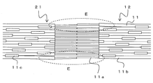
- FIG. 3A is a diagram showing an optical fiber ribbon wire 12.
- a plurality of optical fiber core wires 11 are arranged in parallel, and the adhesive portion 11c is intermittently bonded in the longitudinal direction.
- the optical fiber core wire 11 is configured by arranging a resin coating 11b on the outer periphery of the glass fiber 11a inside, and the resin coating 11b at the tip portion is removed at the time of connection.
- the pitch P of the optical fiber core wire 11 generally coincides with the outer diameter of the optical fiber core wire 11.
- FIG. 3B is a conceptual diagram when such optical fiber ribbon wires 12 are butted against each other and fused. Since the optical fiber ribbon wire 12 has an intermittent adhesive portion for fixing the optical fiber core wires 11, the optical fiber core wires 11 are more optical fibers than the conventional optical fiber tape core wires fixed over the entire length. The part where the core wire 11 is independent is long. Therefore, the degree of freedom in arranging the optical fiber core wires 11 is high, and when the glass fibers 11a are butted against each other, the position of the optical fiber core wires 11 (glass fiber 11a) is likely to shift (part E in the figure). Therefore, this embodiment is particularly effective in the case of an intermittently bonded optical fiber ribbon wire in which a plurality of optical fiber core wires 11 are intermittently bonded in the longitudinal direction.
- this embodiment is particularly effective when the outer diameter of each optical fiber core wire 11 constituting the optical fiber tape core wire or the like is 225 ⁇ m or less. Further, it is more effective when the outer diameter of the optical fiber core wire is narrowed to 200 ⁇ m or less and 170 ⁇ m or less.
- the glass fiber 11a from which the resin coating 11b is removed is conventionally 125 ⁇ m, but if the glass fiber 11a is made thinner, the rigidity of the optical fiber core wire 11 becomes smaller, so that the arrangement of the glass fibers 11a is likely to be disturbed due to the influence of lateral pressure. Become.
- This embodiment is particularly effective when the outer diameter of each glass fiber 11a constituting the optical fiber tape core wire or the like is 110 ⁇ m or less.
- this embodiment is particularly effective when the pitch P between the optical fiber core wires 11 is 225 ⁇ m or less.
- the narrower the pitch P between the optical fiber core wires 11 is 200 ⁇ m or less and 170 ⁇ m or less, the higher the possibility of contact or intersection between the glass fibers 11a, which is more effective.
- this embodiment is particularly effective when the number of cores of the plurality of optical fiber core wires 11 constituting the optical fiber tape core wire or the like is 8 or more. Further, the more the number of optical fiber core wires increases to 12 or more, 16 or more, and 24 or more, the more effective it is.
- the number of cores of the optical fiber cores 11 is large, the pitch P between the optical fiber cores 11 is narrow, and the outer diameter of the optical fiber cores 11 is small. Very effective in some cases.
- the radius of curvature R at the center of the convex curved surface of the tensile strength body 9 in the width direction is larger than the radius at the end in the width direction.
- the inner diameter of the heat-shrinkable tube 5 after shrinkage is about 4 to 6 mm (radius is about 2 to 3 mm), and in this case, the radius of curvature of the tensile strength body 9 on the optical fiber core wire 11 side is, for example, 2 mm or more. (80% or more of the inner radius of the heat-shrinkable tube after shrinkage) is desirable. However, the R of the widthwise end portion of the tensile strength body 9 may be less than 2 mm.
- the inner diameter (major diameter) of the heat melting member 7 is 3.4 to 5 mm and the inner diameter (minor diameter) is 2.0 to 2.5 mm. Further, by setting the inner diameter (major diameter) of the heat melting member 7 to 5 mm, 24 optical fiber core wires 11, a pitch of 200 ⁇ m between the optical fiber core wires 11 and an outer diameter of 200 ⁇ m of the optical fiber core wires 11 are intermittently bonded type light. Reinforcement of the fusion spliced portion of the fiber optic ribbon wire 12 can also be achieved.
- the surface of the tensile strength body 9 on the optical fiber core wire 11 side is formed of a curved surface, it is possible to suppress the arrangement disorder of the optical fiber core wire 11 due to the lateral pressure. Therefore, it is possible to suppress variations in transmission loss for each optical fiber core wire 11.
- the optical fiber core wires 11 can be arranged along a gentle curved surface. For example, if the radius of curvature is too small, the transmission loss may be increased when the optical fiber core wire 11 is arranged along the tensile strength body.
- each optical fiber core wire 11 can be arranged on a gentle curved surface, and the total height of the reinforcing portion can be lowered.
- the shape of the tensile strength body 9 is not limited to the above-mentioned example.
- a tensile strength body 9a may be used as in the reinforcing sleeve 1a shown in FIG. 4A.
- the reinforcing sleeve 1a has the same configuration as the reinforcing sleeve 1 except that the tensile strength body 9a is used.
- the cross-sectional shape of the tensile strength body 9a is a substantially semicircular shape in which the heat melting member 7 side is a convex curved surface, and protrusions 13 are formed below both end portions of the tensile strength body 9a.
- the protrusions 13 are portions at both ends of the tensile strength body 9a that project in the width direction. That is, a step is formed upward in the vicinity of both ends of the tensile strength body 9a.
- FIG. 4B is a cross-sectional view showing a state in which the reinforcing sleeve 1a is contracted.
- the lower surface may be a convex curved surface, for example, an ellipse, instead of flattening the lower surface as in the tensile strength body 9a.
- the tensile strength body 9 has a flat shape having a width wider than that in the height direction.
Landscapes
- Physics & Mathematics (AREA)
- General Physics & Mathematics (AREA)
- Optics & Photonics (AREA)
- Engineering & Computer Science (AREA)
- Plasma & Fusion (AREA)
- Mechanical Coupling Of Light Guides (AREA)
Priority Applications (2)
| Application Number | Priority Date | Filing Date | Title |
|---|---|---|---|
| JP2021550645A JP7508471B2 (ja) | 2019-10-01 | 2020-09-23 | 補強スリーブ、光ファイバ接続部の補強構造及び補強方法 |
| US17/576,341 US11874499B2 (en) | 2019-10-01 | 2022-01-14 | Reinforcement sleeve, and reinforcement structure and reinforcement method for optical fiber connection part |
Applications Claiming Priority (2)
| Application Number | Priority Date | Filing Date | Title |
|---|---|---|---|
| JP2019181579 | 2019-10-01 | ||
| JP2019-181579 | 2019-10-01 |
Related Child Applications (1)
| Application Number | Title | Priority Date | Filing Date |
|---|---|---|---|
| US17/576,341 Continuation US11874499B2 (en) | 2019-10-01 | 2022-01-14 | Reinforcement sleeve, and reinforcement structure and reinforcement method for optical fiber connection part |
Publications (1)
| Publication Number | Publication Date |
|---|---|
| WO2021065606A1 true WO2021065606A1 (ja) | 2021-04-08 |
Family
ID=75336429
Family Applications (1)
| Application Number | Title | Priority Date | Filing Date |
|---|---|---|---|
| PCT/JP2020/035748 Ceased WO2021065606A1 (ja) | 2019-10-01 | 2020-09-23 | 補強スリーブ、光ファイバ接続部の補強構造及び補強方法 |
Country Status (3)
| Country | Link |
|---|---|
| US (1) | US11874499B2 (https=) |
| JP (1) | JP7508471B2 (https=) |
| WO (1) | WO2021065606A1 (https=) |
Citations (7)
| Publication number | Priority date | Publication date | Assignee | Title |
|---|---|---|---|---|
| JPS60102316U (ja) * | 1983-12-16 | 1985-07-12 | 松下電工株式会社 | 安定脚 |
| JPS60102537U (ja) * | 1983-12-20 | 1985-07-12 | トキコ株式会社 | 油圧緩衝器 |
| JPS60112371U (ja) * | 1983-12-28 | 1985-07-30 | 関東自動車工業株式会社 | 塗装ロボツト |
| JPS60112372U (ja) * | 1983-12-29 | 1985-07-30 | 帝国臓器製薬株式会社 | 錠剤のコ−テイング加工に使用するスプレ−ガンのキヤツプカバ− |
| JPS60127140U (ja) * | 1984-01-31 | 1985-08-27 | 三和テッキ株式会社 | 油圧防振器 |
| WO2003019261A1 (fr) * | 2001-08-29 | 2003-03-06 | France Telecom | Procede de protection d'un ensemble de fibres optiques soudees et dispositif associe |
| JP2005024921A (ja) * | 2003-07-02 | 2005-01-27 | Sumitomo Electric Ind Ltd | 融着接続補強装置及び補強方法 |
Family Cites Families (12)
| Publication number | Priority date | Publication date | Assignee | Title |
|---|---|---|---|---|
| JPS6212102U (https=) * | 1985-07-03 | 1987-01-24 | ||
| JPS6212103U (https=) * | 1985-07-05 | 1987-01-24 | ||
| JPS6222609U (https=) * | 1985-07-24 | 1987-02-10 | ||
| JPH087364Y2 (ja) * | 1985-07-24 | 1996-03-04 | 古河電気工業株式会社 | テープ状光ファイバ心線用接続部補強器 |
| JPS6235305U (https=) * | 1985-08-20 | 1987-03-02 | ||
| JPS6432208A (en) | 1987-07-28 | 1989-02-02 | Sumitomo Electric Industries | Reinforcing member for optical fiber fusion splicing part |
| US5832162A (en) * | 1995-12-15 | 1998-11-03 | Tii Industries, Inc. | Multiple fiber fusion splice protection sleeve |
| US6728451B2 (en) * | 1999-09-21 | 2004-04-27 | Tyco Telecommunications (Us) Inc. | Optical fiber holding structure and method of making same |
| JP2004325623A (ja) * | 2003-04-23 | 2004-11-18 | Sumitomo Electric Ind Ltd | 光ファイバ融着接続部補強装置及び融着接続部補強方法 |
| KR101473025B1 (ko) * | 2007-09-07 | 2014-12-15 | 스미토모 덴키 고교 가부시키가이샤 | 보호 슬리브 및 보호 슬리브의 제조 장치 및 제조 방법 |
| JP6381591B2 (ja) * | 2016-08-01 | 2018-08-29 | 株式会社フジクラ | 補強構造 |
| US10185089B2 (en) * | 2016-09-15 | 2019-01-22 | Ofs Fitel, Llc | Splicing optical fiber cable using a mass fusion splicer having a pitch different from cable pitch |
-
2020
- 2020-09-23 JP JP2021550645A patent/JP7508471B2/ja active Active
- 2020-09-23 WO PCT/JP2020/035748 patent/WO2021065606A1/ja not_active Ceased
-
2022
- 2022-01-14 US US17/576,341 patent/US11874499B2/en active Active
Patent Citations (7)
| Publication number | Priority date | Publication date | Assignee | Title |
|---|---|---|---|---|
| JPS60102316U (ja) * | 1983-12-16 | 1985-07-12 | 松下電工株式会社 | 安定脚 |
| JPS60102537U (ja) * | 1983-12-20 | 1985-07-12 | トキコ株式会社 | 油圧緩衝器 |
| JPS60112371U (ja) * | 1983-12-28 | 1985-07-30 | 関東自動車工業株式会社 | 塗装ロボツト |
| JPS60112372U (ja) * | 1983-12-29 | 1985-07-30 | 帝国臓器製薬株式会社 | 錠剤のコ−テイング加工に使用するスプレ−ガンのキヤツプカバ− |
| JPS60127140U (ja) * | 1984-01-31 | 1985-08-27 | 三和テッキ株式会社 | 油圧防振器 |
| WO2003019261A1 (fr) * | 2001-08-29 | 2003-03-06 | France Telecom | Procede de protection d'un ensemble de fibres optiques soudees et dispositif associe |
| JP2005024921A (ja) * | 2003-07-02 | 2005-01-27 | Sumitomo Electric Ind Ltd | 融着接続補強装置及び補強方法 |
Also Published As
| Publication number | Publication date |
|---|---|
| US11874499B2 (en) | 2024-01-16 |
| JP7508471B2 (ja) | 2024-07-01 |
| US20220137297A1 (en) | 2022-05-05 |
| JPWO2021065606A1 (https=) | 2021-04-08 |
Similar Documents
| Publication | Publication Date | Title |
|---|---|---|
| JP6034284B2 (ja) | バンドル構造の製造方法、ファイバ接続構造の製造方法、ファイバの接続方法、ファイバの接続構造 | |
| JP5103213B2 (ja) | コネクタ付き光ファイバケーブルおよび光コネクタ、ならびに光コネクタの組立方法 | |
| US20180149821A1 (en) | Laser sintered flexible ribbon | |
| CN110036325A (zh) | 间断性连结型光纤带芯线及其制造方法、光缆及光纤软线 | |
| CN112888978B (zh) | 具有用于多路熔接的带化接口的光纤扇出组件及其制造方法 | |
| US20080193089A1 (en) | Optical connector connecting method and structure | |
| EP0480453A2 (en) | Method of producing optical fiber coupler | |
| JP5932881B2 (ja) | マルチコアファイバ及びそのマルチコアファイバの製造方法 | |
| EP0137501A2 (en) | Branch off device for multi core optical fiber and production thereof | |
| JP7585057B2 (ja) | 補強スリーブ及び光ファイバ接続部の補強構造 | |
| JP7434027B2 (ja) | 複数の光ファイバ心線とマルチコアファイバとの接続方法 | |
| JP7585056B2 (ja) | 補強スリーブ及び光ファイバ接続部の補強構造 | |
| WO2021065606A1 (ja) | 補強スリーブ、光ファイバ接続部の補強構造及び補強方法 | |
| JP7072408B2 (ja) | 光ファイバ保持部材及び光ファイバ保持部材への光ファイバの配置方法 | |
| JP2024114030A (ja) | 補強スリーブ及び光ファイバ接続部の補強構造 | |
| TWI594035B (zh) | Protective sleeve | |
| JP2014071175A (ja) | 補強スリーブ、光ファイバ接続部の補強方法および補強構造 | |
| WO2022191249A1 (ja) | 光ファイバホルダおよび光ファイバ心線の接続方法 | |
| JP5468915B2 (ja) | ドロップケーブル用補強スリーブ | |
| CN117581138A (zh) | 光纤带 | |
| JPS612110A (ja) | 光フアイバ多心素線 | |
| US11867947B2 (en) | Cable assembly having routable splice protectors | |
| JP2006201264A (ja) | 光ファイバ接続部補強用熱収縮スリーブの加熱装置及び光ファイバ | |
| JPS6061706A (ja) | 光フアイバ接続部の補強方法とその補強部材 | |
| JPS62164008A (ja) | 光分配器の製造方法 |
Legal Events
| Date | Code | Title | Description |
|---|---|---|---|
| 121 | Ep: the epo has been informed by wipo that ep was designated in this application |
Ref document number: 20873104 Country of ref document: EP Kind code of ref document: A1 |
|
| ENP | Entry into the national phase |
Ref document number: 2021550645 Country of ref document: JP Kind code of ref document: A |
|
| NENP | Non-entry into the national phase |
Ref country code: DE |
|
| 122 | Ep: pct application non-entry in european phase |
Ref document number: 20873104 Country of ref document: EP Kind code of ref document: A1 |