WO2021064805A1 - 鞍乗型車両、鞍乗型車両の制御方法及びプログラム - Google Patents
鞍乗型車両、鞍乗型車両の制御方法及びプログラム Download PDFInfo
- Publication number
- WO2021064805A1 WO2021064805A1 PCT/JP2019/038562 JP2019038562W WO2021064805A1 WO 2021064805 A1 WO2021064805 A1 WO 2021064805A1 JP 2019038562 W JP2019038562 W JP 2019038562W WO 2021064805 A1 WO2021064805 A1 WO 2021064805A1
- Authority
- WO
- WIPO (PCT)
- Prior art keywords
- saddle
- vehicle
- detection
- region
- type vehicle
- Prior art date
- Legal status (The legal status is an assumption and is not a legal conclusion. Google has not performed a legal analysis and makes no representation as to the accuracy of the status listed.)
- Ceased
Links
Images


Classifications
-
- B—PERFORMING OPERATIONS; TRANSPORTING
- B62—LAND VEHICLES FOR TRAVELLING OTHERWISE THAN ON RAILS
- B62J—CYCLE SADDLES OR SEATS; AUXILIARY DEVICES OR ACCESSORIES SPECIALLY ADAPTED TO CYCLES AND NOT OTHERWISE PROVIDED FOR, e.g. ARTICLE CARRIERS OR CYCLE PROTECTORS
- B62J45/00—Electrical equipment arrangements specially adapted for use as accessories on cycles, not otherwise provided for
- B62J45/40—Sensor arrangements; Mounting thereof
- B62J45/41—Sensor arrangements; Mounting thereof characterised by the type of sensor
-
- B—PERFORMING OPERATIONS; TRANSPORTING
- B62—LAND VEHICLES FOR TRAVELLING OTHERWISE THAN ON RAILS
- B62J—CYCLE SADDLES OR SEATS; AUXILIARY DEVICES OR ACCESSORIES SPECIALLY ADAPTED TO CYCLES AND NOT OTHERWISE PROVIDED FOR, e.g. ARTICLE CARRIERS OR CYCLE PROTECTORS
- B62J27/00—Safety equipment
-
- B—PERFORMING OPERATIONS; TRANSPORTING
- B62—LAND VEHICLES FOR TRAVELLING OTHERWISE THAN ON RAILS
- B62J—CYCLE SADDLES OR SEATS; AUXILIARY DEVICES OR ACCESSORIES SPECIALLY ADAPTED TO CYCLES AND NOT OTHERWISE PROVIDED FOR, e.g. ARTICLE CARRIERS OR CYCLE PROTECTORS
- B62J45/00—Electrical equipment arrangements specially adapted for use as accessories on cycles, not otherwise provided for
- B62J45/40—Sensor arrangements; Mounting thereof
- B62J45/41—Sensor arrangements; Mounting thereof characterised by the type of sensor
- B62J45/412—Speed sensors
-
- B—PERFORMING OPERATIONS; TRANSPORTING
- B62—LAND VEHICLES FOR TRAVELLING OTHERWISE THAN ON RAILS
- B62J—CYCLE SADDLES OR SEATS; AUXILIARY DEVICES OR ACCESSORIES SPECIALLY ADAPTED TO CYCLES AND NOT OTHERWISE PROVIDED FOR, e.g. ARTICLE CARRIERS OR CYCLE PROTECTORS
- B62J45/00—Electrical equipment arrangements specially adapted for use as accessories on cycles, not otherwise provided for
- B62J45/40—Sensor arrangements; Mounting thereof
- B62J45/41—Sensor arrangements; Mounting thereof characterised by the type of sensor
- B62J45/415—Inclination sensors
- B62J45/4151—Inclination sensors for sensing lateral inclination of the cycle
-
- B—PERFORMING OPERATIONS; TRANSPORTING
- B62—LAND VEHICLES FOR TRAVELLING OTHERWISE THAN ON RAILS
- B62J—CYCLE SADDLES OR SEATS; AUXILIARY DEVICES OR ACCESSORIES SPECIALLY ADAPTED TO CYCLES AND NOT OTHERWISE PROVIDED FOR, e.g. ARTICLE CARRIERS OR CYCLE PROTECTORS
- B62J50/00—Arrangements specially adapted for use on cycles not provided for in main groups B62J1/00 - B62J45/00
- B62J50/20—Information-providing devices
- B62J50/21—Information-providing devices intended to provide information to rider or passenger
- B62J50/22—Information-providing devices intended to provide information to rider or passenger electronic, e.g. displays
-
- G—PHYSICS
- G01—MEASURING; TESTING
- G01S—RADIO DIRECTION-FINDING; RADIO NAVIGATION; DETERMINING DISTANCE OR VELOCITY BY USE OF RADIO WAVES; LOCATING OR PRESENCE-DETECTING BY USE OF THE REFLECTION OR RERADIATION OF RADIO WAVES; ANALOGOUS ARRANGEMENTS USING OTHER WAVES
- G01S13/00—Systems using the reflection or reradiation of radio waves, e.g. radar systems; Analogous systems using reflection or reradiation of waves whose nature or wavelength is irrelevant or unspecified
- G01S13/88—Radar or analogous systems specially adapted for specific applications
- G01S13/93—Radar or analogous systems specially adapted for specific applications for anti-collision purposes
- G01S13/931—Radar or analogous systems specially adapted for specific applications for anti-collision purposes of land vehicles
- G01S2013/9315—Monitoring blind spots
-
- G—PHYSICS
- G01—MEASURING; TESTING
- G01S—RADIO DIRECTION-FINDING; RADIO NAVIGATION; DETERMINING DISTANCE OR VELOCITY BY USE OF RADIO WAVES; LOCATING OR PRESENCE-DETECTING BY USE OF THE REFLECTION OR RERADIATION OF RADIO WAVES; ANALOGOUS ARRANGEMENTS USING OTHER WAVES
- G01S13/00—Systems using the reflection or reradiation of radio waves, e.g. radar systems; Analogous systems using reflection or reradiation of waves whose nature or wavelength is irrelevant or unspecified
- G01S13/88—Radar or analogous systems specially adapted for specific applications
- G01S13/93—Radar or analogous systems specially adapted for specific applications for anti-collision purposes
- G01S13/931—Radar or analogous systems specially adapted for specific applications for anti-collision purposes of land vehicles
- G01S2013/9322—Radar or analogous systems specially adapted for specific applications for anti-collision purposes of land vehicles using additional data, e.g. driver condition, road state or weather data
-
- G—PHYSICS
- G01—MEASURING; TESTING
- G01S—RADIO DIRECTION-FINDING; RADIO NAVIGATION; DETERMINING DISTANCE OR VELOCITY BY USE OF RADIO WAVES; LOCATING OR PRESENCE-DETECTING BY USE OF THE REFLECTION OR RERADIATION OF RADIO WAVES; ANALOGOUS ARRANGEMENTS USING OTHER WAVES
- G01S13/00—Systems using the reflection or reradiation of radio waves, e.g. radar systems; Analogous systems using reflection or reradiation of waves whose nature or wavelength is irrelevant or unspecified
- G01S13/88—Radar or analogous systems specially adapted for specific applications
- G01S13/93—Radar or analogous systems specially adapted for specific applications for anti-collision purposes
- G01S13/931—Radar or analogous systems specially adapted for specific applications for anti-collision purposes of land vehicles
- G01S2013/9327—Sensor installation details
- G01S2013/93272—Sensor installation details in the back of the vehicles
-
- G—PHYSICS
- G01—MEASURING; TESTING
- G01S—RADIO DIRECTION-FINDING; RADIO NAVIGATION; DETERMINING DISTANCE OR VELOCITY BY USE OF RADIO WAVES; LOCATING OR PRESENCE-DETECTING BY USE OF THE REFLECTION OR RERADIATION OF RADIO WAVES; ANALOGOUS ARRANGEMENTS USING OTHER WAVES
- G01S13/00—Systems using the reflection or reradiation of radio waves, e.g. radar systems; Analogous systems using reflection or reradiation of waves whose nature or wavelength is irrelevant or unspecified
- G01S13/88—Radar or analogous systems specially adapted for specific applications
- G01S13/93—Radar or analogous systems specially adapted for specific applications for anti-collision purposes
- G01S13/931—Radar or analogous systems specially adapted for specific applications for anti-collision purposes of land vehicles
- G01S2013/9327—Sensor installation details
- G01S2013/93274—Sensor installation details on the side of the vehicles
Definitions
- the present invention relates to a saddle-mounted vehicle, a control method and a program for a saddle-mounted vehicle.
- Patent Document 1 discloses a technique of detecting the situation behind the own vehicle and notifying the driver of the existence of the other vehicle by blinking a lamp or the like when another vehicle is detected in the rear detection area. ing.
- Patent Document 1 since the setting of the rear detection area is fixed during straight-ahead driving and turning, the driver can visually recognize the rear detection area depending on the turning direction and turning radius of the vehicle. A difficult area (blind area) may occur.
- An object of the present invention is to provide a technique capable of changing the setting of the detection area in the rear detection unit based on the turning direction and the turning radius of the saddle-type vehicle in view of the problems of the prior art.
- the saddle-mounted vehicle has a rear detection means for detecting an object in a detection region behind the vehicle and a notification for notifying the driver when the object is detected by the rear detection means.
- a saddle-type vehicle having means and An acquisition means for acquiring the traveling information of the saddle-type vehicle, and A specific means for specifying the turning direction and turning radius of the saddle-type vehicle based on the traveling information, and It is characterized by including a changing means for changing the setting of the detection area when traveling straight in the rear detecting means based on the turning direction and the turning radius.
- the method for controlling a saddle-type vehicle is to the rear detecting means for detecting an object in the detection region behind the vehicle and to the driver when the object is detected by the rear detecting means. It is a control method of a saddle-type vehicle having a notification means for performing notification.
- the acquisition process of acquiring the traveling information of the saddle-type vehicle and the acquisition means A specific step in which the specific means specifies the turning direction and turning radius of the saddle-type vehicle based on the traveling information.
- the changing means includes a changing step of changing the setting of the detection area when traveling straight in the rear detecting means based on the turning direction and the turning radius.
- the present invention it is possible to change the setting of the detection area in the rear detection unit based on the turning direction and turning radius of the saddle-type vehicle.
- the accompanying drawings are included in the specification and are used to form a part thereof, show embodiments of the present invention, and explain the principles of the present invention together with the description thereof.
- the block diagram which shows the functional structure of the detection area control device.
- the figure explaining the process flow of the detection area control apparatus The figure which illustrates the table of 2nd Embodiment.
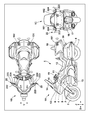
- FIG. 1 is a diagram illustrating a configuration of a saddle-mounted vehicle 1 according to an embodiment of the present invention.
- 1A of FIG. 1 is a left side view of the saddle-mounted vehicle 1
- 1B of FIG. 1 is a top view of the saddle-mounted vehicle 1
- 1C of FIG. 1 is a rear view of the saddle-mounted vehicle 1.
- the X direction indicates the front-rear direction of the saddle-mounted vehicle 1
- the Y direction indicates the vehicle width direction of the saddle-mounted vehicle 1.
- the Z direction indicates the vertical direction of the saddle-mounted vehicle 1.
- the front wheels 2 are pivotally supported by the lower ends of a pair of left and right front forks 3.
- the upper parts of the left and right front forks 3 are pivotally supported by the head pipe 6 at the front end of the vehicle body frame 5 via the steering stem 4.
- the saddle-mounted vehicle 1 is steered by the handlebar 19 attached to the head pipe 6. Handle grips gripped by the driver are provided at the left and right ends of the handlebar 19. Further, the handlebar 19 is provided with a brake lever, a clutch lever, and the like adjacent to the left and right handle grips (not shown).
- the rear wheel 7 of the saddle-mounted vehicle 1 is pivotally supported by the rear end of the arm 8 extending forward and backward on the lower rear side of the vehicle body.
- the front end portion of the arm 8 is pivotally supported so as to be swingable up and down at the front-rear intermediate portion of the vehicle body frame 5.
- the engine (internal combustion engine) 10 which is the prime mover of the saddle-mounted vehicle 1, is mounted on the body frame 5.
- a fuel tank 11 is arranged above the engine 10, and a seat 12 on which the driver of the motorcycle 1 is seated is arranged behind the fuel tank 11.
- a trunk case 18 for storing articles is arranged at the rear of the seat 12 on which the driver sits.
- a front cowl 13 supported by a vehicle body frame 5 is mounted on the front portion of the vehicle body.
- a screen 14 is provided on the upper front side of the front cowl 13.
- the meter panel 15 is arranged inside the front cowl 13 and the screen 14.
- the meter panel 15 displays various information such as vehicle speed, engine speed, and other vehicle conditions.
- a tail winker 16 and a tail light 17 are provided at the rear portion of the saddle-mounted vehicle 1.
- radars 101 and 102 are arranged as rear detection units 100 for detecting an object in the detection region behind the vehicle.
- the radars 101 and 102 are arranged at the left and right rear positions of the saddle-mounted vehicle 1, respectively.
- the radar 101 detects an object in the detection region on the left rear side of the saddle-mounted vehicle 1.
- the radar 102 detects an object in the detection region on the right rear side of the saddle-mounted vehicle 1.
- the arrangement of the rear detection unit 100 shown in FIG. 1 is an example, and a single radar may be arranged in the rear center of the saddle-mounted vehicle 1, or two radars may be arranged in the left and right rear. , One radar may be placed in the rear center.
- the type of sensor in the rear detection unit 100 may be, for example, a lidar in addition to the radar.
- the rear detection unit 100 is arranged in the trunk case 18, but the arrangement of the rear detection unit 100 is not limited to this position.
- the inside of the saddle back 20 of the saddle-mounted vehicle 1 can also be a location where the rear detection unit 100 is arranged.
- Left and right mirror units 22 are provided in the vehicle width direction (y direction) of the saddle-mounted vehicle 1.
- the left and right mirror units 22 include a mirror housing 222, side mirrors (mirror surface portions) 223, and a notification display unit 224.
- the mirror housing 222 is a hollow body having an opening on the rear side, and a side mirror (mirror surface portion) 223 is attached to the mirror housing 222 so as to close the opening. The driver can visually recognize the left and right rear by the side mirror 223.
- the saddle-mounted vehicle 1 of the present embodiment has a notification unit that notifies the driver when an object is detected by the rear detection unit 100.
- the notification display unit 224 of the mirror unit 22 functions as a notification unit that notifies the driver.
- the notification display unit 224 is a light emitting device including a light emitting element such as an LED, a substrate that supports the light emitting element, and a cover lens or the like that covers the front surface of the notification display unit 224. By forming an opening in a part of the side mirror 223 and arranging the notification display unit 224 in the opening, the notification display unit 224 can be provided in the mirror unit 22.
- the arrangement of the notification display unit 224 shown in FIG. 1 is an example, and the arrangement of the notification display unit 224 is not limited to this position.
- the meter panel 15 can also be a location for the notification display unit 224.
- FIG. 2 is a block diagram showing a functional configuration of the detection area control device 200 according to the present embodiment.
- the saddle-mounted vehicle 1 is provided with a rear detection unit 100, a traveling information detection unit 150, and a detection area control device 200.
- the traveling information detection unit 150 detects traveling information (bank angle, vehicle speed, yaw rate, steering angle) indicating the traveling state of the saddle-mounted vehicle 1.
- the detection area control device 200 can change the setting of the detection area in the rear detection unit 100 based on the travel information indicating the traveling state of the saddle-mounted vehicle 1.
- the detection area control device 200 includes an interface unit 201 (IF unit), a specific unit 202, a change unit 203, a traveling area determination unit 204, a storage unit 205 (ROM205a, RAM205b), and a notification control unit 206.
- the specific unit 202, the change unit 203, and the traveling area determination unit 204 which are functional configurations for performing calculation and determination processing, are read from, for example, one or a plurality of CPUs (central processing units) or a storage unit 205.
- the functions of each part are configured using the program.
- the functional configuration of each part may be configured by an integrated circuit or the like as long as it fulfills the same function.
- the interface unit 201 functions as an interface between the rear detection unit 100, the traveling information detection unit 150, and the notification display unit 224, and the interface unit 201 is subjected to, for example, data communication by a predetermined communication protocol.
- a predetermined communication protocol Includes communication interfaces that allow.
- the communication protocol includes, for example, K-Line communication, CAN communication, serial communication, and the like.
- the interface unit 201 can acquire travel information (bank angle, vehicle speed, yaw rate, steering angle) indicating the travel state of the saddle-mounted vehicle 1 detected by the travel information detection unit 150.
- the traveling information detection unit 150 can detect traveling information indicating the traveling state of the saddle-mounted vehicle 1, and the traveling information detecting unit 150 can detect, for example, a plurality of types of traveling information mounted on the saddle-mounted vehicle 1. Sensors (eg, bank angle sensor 151, vehicle speed sensor 152, yaw rate sensor 153, steering angle sensor 154, etc.) are included.
- the bank angle sensor 151 is a sensor that detects the inclination angle (bank angle ⁇ : FIG. 3) of the saddle-mounted vehicle 1. It is also possible to use a G sensor instead of the bank angle sensor 151.
- the G sensor (accelerometer) is a sensor that measures the acceleration (speed change rate) of the saddle-mounted vehicle 1 and can measure the acceleration in the three axes (X-axis, Y-axis, and Z-axis). is there. For example, as shown in FIG. 3, the inclination angle of the saddle-mounted vehicle 1 can be detected based on the measured value in the Y direction of the G sensor.
- the vehicle speed sensor 152 is a sensor that detects the traveling speed of the saddle-mounted vehicle 1, and for example, detects the rotation speed (speed) according to the number of rotations of the wheels of the saddle-mounted vehicle 1. Further, the yaw rate sensor 153 detects the yaw rate (rotation angular velocity) of the saddle-mounted vehicle 1. The steering angle sensor 154 detects the steering angle of the handlebar 19 of the saddle-mounted vehicle 1. The bank angle sensor 151, the vehicle speed sensor 152, the yaw rate sensor 153, and the steering angle sensor 154 repeatedly execute detection when the ignition of the saddle-mounted vehicle 1 is turned on.
- the specific unit 202 describes the turning direction and turning radius of the saddle-mounted vehicle 1 based on the traveling information (yaw rate, steering angle, bank angle, vehicle speed) of the saddle-mounted vehicle 1 acquired by the interface unit 201 (IF unit). To identify.
- the identification unit 202 specifies the turning direction based on, for example, the yaw rate or the steering angle in the traveling information. Further, the specifying unit 202 specifies the turning radius in the turning direction based on, for example, the bank angle and the vehicle speed in the traveling information.
- FIG. 3 is a diagram for explaining an example of calculation for obtaining the turning radius.
- the gravitational acceleration is g
- the bank angle (tilt angle) of the saddle-type vehicle 1 is ⁇ .
- the specific unit 202 can acquire the turning radius by sequentially executing arithmetic processing based on this relational expression in the traveling path.
- the specific unit 202 can acquire the bank angle ⁇ as the detection result of the bank angle sensor 151 and the vehicle speed V as the detection result of the vehicle speed sensor 152, and the specific unit 202 can acquire the bank angle ⁇ and the vehicle speed V as the detection result of the vehicle speed sensor 152.
- the turning radius r is specified by using the detection results of the bank angle sensor 151 and the vehicle speed sensor 152, but the calculation based on the above relational expression is an example, and is not limited to this example. Absent. For example, it is also possible to specify the turning radius r by using the detection result of the bank angle sensor 151 (bank angle (tilt angle): ⁇ ) and the detection result of the yaw rate sensor 153 (rotation angular velocity ⁇ ).
- the changing unit 203 changes the setting of the detection area when traveling straight in the rear detecting unit 100 based on the turning direction and turning radius.
- the changing unit 203 changes the shape of the detection area set when traveling straight ahead in the detection area of the rear detecting unit 100 to a curved region having a curved shape according to the turning direction and the turning radius.
- the specific unit 202 described above specifies the turning radius in the turning direction acquired based on the bank angle and the vehicle speed as the radius of curvature of the curved region.
- the specific unit 202 acquires the average bank angle within the time and the average vehicle speed based on the bank angle and the vehicle speed sequentially acquired within the set time.
- the specific unit 202 can correct the radius of curvature of the curved region based on the average bank angle and the average vehicle speed. This makes it possible to correct the setting of the curved region, which is the detection region of the rear detection unit, according to the state of turning.
- FIG. 4 is a diagram for explaining the deformation processing of the detection area by the change unit 203.
- FIG. 4 shows an example in which radars 101 and 102 are arranged on the left and right as the rear detection unit 100 of the saddle-mounted vehicle 1.
- the radar arrangement in FIG. 4 is an example, and the same can be applied to a configuration in which a single radar is arranged in the rear center of the saddle-mounted vehicle 1.
- the detection area of the rear detection unit 100 is a region having a two-dimensional spread.
- the shape of the detection area set when traveling straight ahead in the detection area of the rear detection unit 100 is modeled as a rectangular area shape for simplification (detection areas 401a and 401b).
- the detection areas 401a and 401b shown by the broken lines are the detection areas set when traveling straight ahead (hereinafter, also referred to as “detection area before change”) in the detection area of the rear detection unit 100, and the detection area 401a before change is , Corresponds to the detection area on the left rear side of the saddle-mounted vehicle 1 by the radar 101. Further, the detection area 401b before the change corresponds to the detection area on the right rear side of the saddle-type vehicle 1 by the radar 102.
- the change unit 203 changes the shape of the detection area before the change to a curved area having a curved shape according to the turning direction and the turning radius (hereinafter, also referred to as “the detected area after the change”).
- the area shown by the solid line indicates the detection area after the change by the change unit 203, and the curved area 402a after the change corresponds to the detection area on the left rear side of the saddle-mounted vehicle 1 by the radar 101. Further, the modified curved region 402b corresponds to the detection region on the right rear side of the saddle-mounted vehicle 1 by the radar 102.
- the saddle-mounted vehicle 1 shows an example of turning right, and the turning radius in the turning track 420 is r.
- the change unit 203 sets the detection area when traveling straight in the rear detection unit 100 (the detection area set in a rectangular shape (detection area 401a, detection area 401b)) to the turning direction and turning radius of the saddle-type vehicle 1. Change based on. That is, the changing unit 203 changes the shape (rectangular detection area) of the detection area set when traveling straight ahead in the detection area of the rear detection unit 100 according to the turning direction (right turning) and the turning radius (r). It is changed to a curved region (curved region 402a, curved region 402b) having a curved shape.
- the rear detection unit 100 since the other vehicle 410 traveling behind the saddle-mounted vehicle 1 (own vehicle) is traveling outside the detection area in the detection area 401a and the detection area 401b before the change, the rear detection unit Not detected by 100. However, when the shape of the detection region is changed to a curved region having a curved shape according to the turning direction and the turning radius, since the other vehicle 410 is traveling in the changed curved region 402a, the rear detection unit 100 causes the detection region to travel. Detected. In this way, by changing the setting of the detection area in the rear detection unit 100 when traveling straight ahead based on the turning direction and turning radius of the saddle-mounted vehicle, it is possible to prevent detection omission and erroneous detection.
- the traveling area determination unit 204 determines that the saddle-mounted vehicle 1 is in a high-speed traveling state equal to or higher than the threshold speed or in a low-speed traveling state lower than the threshold speed. Determine if there is.
- the changing unit 203 changes the size of the curved region (curved region 402a and curved region 402b in FIG. 4) based on the determination result of the traveling area determination unit 204.
- the changing unit 203 When the saddle-type vehicle 1 is in a high-speed traveling state, the changing unit 203 has the length of the curved region corresponding to the front-rear direction (X direction) of the saddle-type vehicle 1 and the vehicle of the saddle-type vehicle 1. Of the lengths in the width direction of the curved region corresponding to the width direction (Y direction), at least one of them is lengthened to change (enlarge) the size of the curved region.
- the length of the curved region in the front-rear direction (L1 in FIG. 4) and the curvature are curved according to the vehicle speed V.
- the size of the curved region is changed (enlarged) by increasing the length of at least one of the lengths in the width direction of the region (W1 in FIG. 4).
- the changing portion 203 bends by lengthening one of the length of the curved region in the front-rear direction and the length of the curved region in the width direction by a predetermined value. Resize (enlarge) the area. This makes it possible to perform detection in a wide detection area, and detection suitable for high-speed driving becomes possible.
- the changing unit 203 sets the length of the curved region corresponding to the front-rear direction (X direction) of the saddle-mounted vehicle 1 and the saddle-mounted vehicle 1 in the front-rear direction.
- the size of the curved region is changed (reduced) by shortening at least one of the lengths of the curved region corresponding to the vehicle width direction (Y direction).
- the vehicle speed V of the saddle-mounted vehicle 1 detected by the vehicle speed sensor 152 is less than the threshold speed Vth (V ⁇ Vth), the length of the curved region in the front-rear direction (L1 in FIG. 4) and the length in the front-rear direction according to the vehicle speed V.
- the size of the curved region is changed (reduced) by shortening at least one of the lengths of the curved region in the width direction (W1 in FIG. 4).
- the changing portion 203 bends by shortening the length of either the front-rear direction of the curved region or the width direction of the curved region by a predetermined value. Resize (reduce) the area. As a result, by narrowing the detection area, detection suitable for low-speed running becomes possible.
- the storage unit 205 is composed of a ROM 205a (Read Only Memory) and a RAM 205b (Random Access Memory).
- the ROM 205a stores various tables used by the change unit 203 in the detection area change process. For example, the ROM 205a stores a table that associates the speed of the saddle-mounted vehicle 1 with the length in the front-rear direction of the curved region (L1 in FIG. 4) and the length in the width direction of the curved region (W1 in FIG. 4). Has been done.
- the changing unit 203 Compared with the process of changing the size of the curved area by sequential calculation, the changing unit 203 refers to the table of ROM 205a to perform the process of changing (enlarging or reducing) the size of the curved area easily and quickly. Can be done.
- the RAM 205b can store the time-series detection information for a predetermined time detected by various sensors of the traveling information detection unit 150. Further, the RAM 205b functions as a work area for processing executed by the specific unit 202, the change unit 203, and the traveling area determination unit 204.
- the notification control unit 206 controls the display of the notification display unit 224 in order to notify the driver that an object has been detected.
- the rear detection unit 100 executes the detection process in the curved region after the size change changed by the change unit 203. Then, when an object is detected in the detection region (curved region after resizing) behind the vehicle by the rear detection unit 100, the notification control unit 206 controls the display of the notification display unit 224, and the rear detection unit 100 controls the display. Control is performed to notify the driver that an object has been detected.
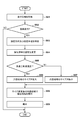
- FIG. 5 is a diagram illustrating a processing flow of the detection area control device 200.
- step S51 the interface unit 201 (IF unit) acquires traveling information (bank angle, vehicle speed, yaw rate, steering angle) indicating the traveling state of the saddle-mounted vehicle 1 detected by the traveling information detection unit 150.
- traveling information bank angle, vehicle speed, yaw rate, steering angle
- step S52 the specific unit 202 determines whether the saddle-mounted vehicle 1 is turning based on the traveling information (bank angle, vehicle speed, yaw rate, steering angle).
- the processing flow ends.
- the specific unit 202 determines that the saddle-mounted vehicle 1 is turning in the determination of step S52 (S52-Yes)
- the specific unit 202 advances the process to step S53.
- step S53 the specific unit 202 turns the saddle-mounted vehicle 1 based on the traveling information (yaw rate, steering angle, bank angle, vehicle speed) of the saddle-mounted vehicle 1 acquired by the interface unit 201 (IF unit). Specify the direction and turning radius.
- step S54 the changing unit 203 changes the setting of the detection area when traveling straight in the rear detecting unit 100 based on the turning direction and the turning radius.
- the changing unit 203 has a shape in which the shape of the detection area set during straight-ahead travel in the detection area of the rear detection unit 100 is curved according to the turning direction and the turning radius. Change to the curved area of.
- step S55 the traveling area determination unit 204 determines that the saddle-mounted vehicle 1 is in a high-speed traveling state equal to or higher than the threshold speed or is less than the threshold speed based on the comparison between the vehicle speed of the saddle-type vehicle 1 and the threshold speed. Determine if the vehicle is running at low speed.
- step S55 when the saddle-mounted vehicle 1 is in the high-speed traveling state (S55-Yes), the traveling area determination unit 204 advances the process to step S56.
- the change unit 203 has the length of the curved region corresponding to the front-rear direction (X direction) of the saddle-type vehicle 1 in the front-rear direction (L1 in FIG. 4) and the vehicle width direction of the saddle-type vehicle 1 (Y).
- the size of the curved region is changed (enlarged) by lengthening at least one of the lengths (W1 in FIG. 4) of the curved region corresponding to the direction).
- step S55 when the saddle-mounted vehicle 1 is in the low-speed traveling state (S55-No), the traveling area determination unit 204 proceeds to the process in step S57.
- the changing portion 203 has the length of the curved region corresponding to the front-rear direction (X direction) of the saddle-type vehicle 1 in the front-rear direction (L1 in FIG. 4) and the vehicle width direction of the saddle-type vehicle 1.
- the size of the curved region is changed (reduced) by shortening at least one of the lengths in the width direction (W1 in FIG. 4) corresponding to (Y direction).
- step S58 the rear detection unit 100 executes the detection process in the curved region after the size change. That is, the rear detection unit 100 detects an object in the detection region (curved region after resizing) behind the vehicle. For example, as described with reference to FIG. 4, another vehicle 410 (FIG. 4) traveling in the curved region 402a behind the saddle-mounted vehicle 1 (own vehicle) is detected by the rear detection unit 100.
- the process proceeds to step S59.
- step S59 the notification control unit 206 controls the display of the notification display unit 224 to notify the driver that an object has been detected by the rear detection unit 100.
- the ROM 205a stores the area pattern according to the turning direction and the turning radius.
- FIG. 6 is a diagram illustrating a table of area patterns stored in the ROM 205a, and if the turning direction and turning radius of the saddle-type vehicle 1 are specified by the specifying unit 202, the changing unit 203 will change the specified turning. It is possible to identify the region pattern corresponding to the direction and the turning radius by referring to the table. For example, when the turning radius is r1 in the right turn, the changing unit 203 specifies the pattern 1, and when the turning radius is r2 in the right turning, the changing unit 203 specifies the pattern 2. In the example of the table shown in FIG. 6, the area pattern in the case of turning right is shown, but the same applies to turning left.
- the length in the X direction indicates the length in the front-rear direction of the area pattern corresponding to the front-rear direction of the saddle-type vehicle 1
- the length in the Y direction corresponds to the vehicle width direction of the saddle-type vehicle 1.
- the length of the area pattern in the width direction is shown. In each region pattern, different values are set for the length in the front-rear direction and the length in the width direction.
- the changing unit 203 determines the length of the region pattern corresponding to the front-rear direction (X direction) of the saddle-type vehicle 1 and the saddle in the front-rear direction. It is possible to change (enlarge) the size of the area pattern by increasing at least one of the lengths in the width direction of the area pattern corresponding to the vehicle width direction of the riding vehicle 1.
- the changing unit 203 determines the length of the region pattern corresponding to the front-rear direction (X direction) of the saddle-mounted vehicle 1 in the front-rear direction. It is possible to change (reduce) the size of the area pattern by shortening at least one of the lengths in the width direction of the area pattern corresponding to the vehicle width direction of the saddle-mounted vehicle 1.
- the changing unit 203 uses this area pattern to change the shape of the detection area set when traveling straight out of the detection areas of the rear detection unit 100. Change to a region with a shape from which the region pattern has been removed.
- FIG. 7 is a diagram illustrating a deformation process of the detection region by the change unit 203 of the second embodiment.
- FIG. 7 shows an example in which radars 101 and 102 are arranged on the left and right as the rear detection unit 100 of the saddle-mounted vehicle 1.
- the radar arrangement in FIG. 7 is an example, and the same can be applied to a configuration in which a single radar is arranged in the rear center of the saddle-mounted vehicle 1.
- the shape of the detection area set when traveling straight ahead in the detection area of the rear detection unit 100 is modeled as a rectangular area shape for simplification.
- the detection areas 701a and 701b shown by the solid lines are the detection areas set when traveling straight ahead (hereinafter, “detection area before change”) among the detection areas of the rear detection unit 100, and the detection area 701a before the change is the radar. Corresponds to the detection area on the left rear side of the saddle-mounted vehicle 1 by 101. Further, the detection area 701b before the change corresponds to the detection area on the right rear side of the saddle-type vehicle 1 by the radar 102.
- the area pattern 710 shown by the broken line corresponds to the pattern 1 (right turn, turning radius r1) shown in the table of FIG.
- the changing unit 203 changes the shape of the detection region before the change to a region having a shape obtained by removing the region pattern 710 from the shape (701a) (hereinafter, “detection region after the change”).
- the area pattern 710 is from the detection area 701a located outside the turning track (turning track 720). Is being removed.
- the example of removing the region pattern from the detection region before the change is not limited to this example, and the region pattern 710 may be removed from the detection region 701a and the detection region 701b before the change.
- the other vehicle 750 behind the saddle-mounted vehicle 1 (own vehicle) is located in the area removed from the detection area 701a before the change by the area pattern 710, and is not detected by the rear detection unit 100.
- the changing unit 203 changes the shape of the detection area set when traveling straight ahead in the detection area of the rear detecting unit 100 to a region having a shape obtained by removing the region pattern from the shape. This prevents the other vehicle 750 traveling at a position away from the turning track (turning track 720) from being erroneously detected as another vehicle following the saddle-mounted vehicle 1 (own vehicle) during turning. Is possible.
- the rear detection means for example, 101, 102 in FIG. 1, 100 in FIG. 2 for detecting an object in the detection region behind the vehicle, and the rear detection means (100, 101, In a saddle-type vehicle (for example, 1 in FIG. 1) having a notification means (for example, 224 in FIGS. 1 and 2) for notifying the driver when the object is detected by 102).
- An acquisition means for example, 201 in FIG. 2) for acquiring the traveling information of the saddle-mounted vehicle (1), and With the specific means for specifying the turning direction and turning radius of the saddle-type vehicle based on the traveling information (for example, 202 in FIG. 2),
- the rear detecting means (100, 101, 102) includes a changing means (for example, 203 in FIG. 2) for changing the setting of the detection area during straight running, based on the turning direction and the turning radius.
- the setting of the detection area in the rear detection unit can be changed based on the turning direction and the turning radius of the saddle-mounted vehicle. Further, by changing the setting of the detection area in the rear detection unit based on the turning direction and the turning radius of the saddle-type vehicle, it is possible to prevent detection omission and erroneous detection.
- the changing means (203) has a shape of a detection area set during straight-ahead traveling in the detection areas of the rear detection means (100, 101, 102). Is changed to a curved region (for example, 401a, 401b in FIG. 4) having a curved shape according to the turning direction and the turning radius.
- the detection omission is prevented by changing the shape of the detection region set when traveling straight to a curved region having a curved shape according to the turning direction and the turning radius. Is possible.
- the saddle-mounted vehicle (1) of the above embodiment is further provided with a storage means (for example, 205 in FIG. 2) for storing a region pattern corresponding to the turning direction and turning radius.
- the changing means (203) changes the shape of the detection region (for example, 701a in FIG. 7) set during the straight running out of the detection regions of the rear detecting means (100, 101, 102) from the shape to the region.
- the pattern (eg, 710 in FIG. 7) is changed to a region of the removed shape (eg, 701a-710).
- erroneous detection can be prevented by changing the shape of the detection region to a region having a shape obtained by removing the region pattern from the shape.
- the saddle-type vehicle (1) of the above-described embodiment wherein the acquisition means (201) is the saddle-type vehicle (1) detected by a yaw rate sensor (for example, 153 in FIG. 2) as the travel information. And the steering angle of the saddle-mounted vehicle (1) detected by the steering angle sensor (for example, 154 in FIG. 2).
- the identifying means (202) identifies the turning direction based on the yaw rate or the steering angle.
- the acquisition means (201) is the saddle-type vehicle (1) detected by a bank angle sensor (for example, 151 in FIG. 2) as the travel information. ) And the vehicle speed of the saddle-mounted vehicle (1) detected by the vehicle speed sensor (for example, 152 in FIG. 2).
- the specifying means (202) specifies the turning radius in the turning direction acquired based on the bank angle and the vehicle speed as the radius of curvature of the curved region.
- the saddle-mounted vehicle of the configuration 5 it is possible to calculate the turning radius in the direction in which the detection region is curved, and the turning radius in the turning direction can be specified as the radius of curvature of the curved region.
- the saddle-type vehicle based on the comparison between the vehicle speed and the threshold speed, the saddle-type vehicle is in a high-speed running state equal to or higher than the threshold speed or is less than the threshold speed. Further provided with a traveling area determination means (for example, 204 in FIG. 2) for determining whether or not the vehicle is in a low-speed traveling state.
- the changing means (203) changes the size of the curved region based on the result of the determination.
- the size of the curved region can be changed based on the running state of the saddle-mounted vehicle.
- the changing means (203) is used when the saddle-mounted vehicle is in a high-speed traveling state (for example, vehicle speed V ⁇ threshold speed Vth).
- the length of at least one of W1) in FIG. 4 is increased to change the size of the curved region (for example, 402a and 402b in FIG. 4).
- the saddle-mounted vehicle of configuration 7 it is possible to change the size of the curved region suitable for high-speed driving based on the traveling state of the saddle-mounted vehicle.
- the changing means (203) is used when the saddle-mounted vehicle is in a low-speed traveling state (for example, vehicle speed V ⁇ threshold speed Vth).
- the length of at least one of W1) in FIG. 4 is shortened to change the size of the curved region.
- the saddle-mounted vehicle of the configuration 8 it is possible to change the size of the curved region suitable for low-speed traveling based on the traveling state of the saddle-mounted vehicle.
- the specific means (202) has an average bank angle within the time based on the bank angle sequentially acquired within a set time and the vehicle speed. And get the average vehicle speed, The specific means (202) corrects the radius of curvature of the curved region based on the average bank angle and the average vehicle speed.
- the radius of curvature of the curved region can be corrected based on the acquired average bank angle and average vehicle speed. This makes it possible to correct the setting of the curved region, which is the detection region of the rear detection unit, according to the state of turning.
- the method for controlling a saddle-mounted vehicle includes a rear detecting means (for example, 101, 102 in FIG. 1, 100 in FIG. 2) for detecting an object in a detection region behind the vehicle, and the rear detecting means (100, 100, According to a control method (for example, FIG. 5) of a saddle-type vehicle (for example, 1 in FIG. 1) having a notification means for notifying the driver when the object is detected by 101, 102).
- the acquisition means (for example, 201 in FIG. 2) acquires the traveling information of the saddle-type vehicle (for example, S51 in FIG. 5).
- a specific step for example, S53 in FIG. 5) in which the specific means (for example, 202 in FIG.
- a changing step (for example, FIG. 2) in which the changing means (for example, 203 in FIG. 2) changes the setting of the detection area when traveling straight in the rear detecting means (100, 101, 102) based on the turning direction and the turning radius. 5 S54) and.
- the setting of the detection area in the rear detection unit can be changed based on the turning direction and the turning radius of the saddle-type vehicle. Further, by changing the setting of the detection area in the rear detection unit based on the turning direction and the turning radius of the saddle-type vehicle, it is possible to prevent detection omission and erroneous detection.
- the control method of the saddle-mounted vehicle of the above embodiment is a detection area of the detection areas of the rear detection means (100, 101, 102) set during straight-ahead travel.
- the shape is changed to a curved region (for example, 401a, 401b in FIG. 4) having a curved shape according to the turning direction and the turning radius.
- the detection omission is prevented by changing the shape of the detection region set during straight running to a curved region having a curved shape according to the turning direction and the turning radius. It is possible to prevent it.
- the method for controlling a saddle-mounted vehicle is a pattern acquisition step (for example, for example) of acquiring the turning pattern from a storage means (for example, 205 in FIG. 2) that stores a region pattern corresponding to the turning direction and the turning radius. It also has 710) in FIG.
- the change step the shape of the detection region set during the straight running of the detection regions of the rear detection means (100, 101, 102) is changed to a region having a shape obtained by removing the region pattern from the shape (the shape is changed). For example, 701a-710).
- erroneous detection can be prevented by changing the shape of the detection region to a region having a shape obtained by removing the region pattern from the shape.
- Configuration 13 The program of the above-described embodiment causes a computer to execute each step of the saddle-type vehicle control method according to any one of the configurations 10 to 12.
- the present invention supplies a program that realizes one or more functions of the above-described embodiment to a system or device via a network or storage medium, and one or more processors in the computer of the system or device reads and executes the program. It can also be realized by the processing to be performed. It can also be realized by a circuit (for example, ASIC) that realizes one or more functions.
- a circuit for example, ASIC
- 1 Saddle-type vehicle, 100: Rear detection unit, 101, 102: Radar 150: Driving information detection unit, 151: Bank angle sensor, 152: Vehicle speed sensor, 153: Yaw rate sensor, 154: Steering angle sensor, 200: Detection area control device, 201: Interface unit (acquisition unit), 202: Specific part, 203: Change part, 204: Travel area judgment part, 206: Notification control unit, 224: Notification display unit
Landscapes
- Engineering & Computer Science (AREA)
- Mechanical Engineering (AREA)
- Radar, Positioning & Navigation (AREA)
- Remote Sensing (AREA)
- Physics & Mathematics (AREA)
- Electromagnetism (AREA)
- Computer Networks & Wireless Communication (AREA)
- General Physics & Mathematics (AREA)
- Control Of Driving Devices And Active Controlling Of Vehicle (AREA)
- Traffic Control Systems (AREA)
Priority Applications (5)
| Application Number | Priority Date | Filing Date | Title |
|---|---|---|---|
| DE112019007769.4T DE112019007769T5 (de) | 2019-09-30 | 2019-09-30 | Fahrzeug vom spreizsitz-typ, verfahren zum steuern eines fahrzeugs vom spreizsitz-typ und programm |
| PCT/JP2019/038562 WO2021064805A1 (ja) | 2019-09-30 | 2019-09-30 | 鞍乗型車両、鞍乗型車両の制御方法及びプログラム |
| JP2021550763A JP7291232B2 (ja) | 2019-09-30 | 2019-09-30 | 鞍乗型車両、鞍乗型車両の制御方法及びプログラム |
| CN201980100457.0A CN114423673B (zh) | 2019-09-30 | 2019-09-30 | 跨骑式车辆、跨骑式车辆的控制方法以及存储介质 |
| US17/699,720 US11827302B2 (en) | 2019-09-30 | 2022-03-21 | Straddle type vehicle, method for controlling straddle type vehicle, and storage medium |
Applications Claiming Priority (1)
| Application Number | Priority Date | Filing Date | Title |
|---|---|---|---|
| PCT/JP2019/038562 WO2021064805A1 (ja) | 2019-09-30 | 2019-09-30 | 鞍乗型車両、鞍乗型車両の制御方法及びプログラム |
Related Child Applications (1)
| Application Number | Title | Priority Date | Filing Date |
|---|---|---|---|
| US17/699,720 Continuation US11827302B2 (en) | 2019-09-30 | 2022-03-21 | Straddle type vehicle, method for controlling straddle type vehicle, and storage medium |
Publications (1)
| Publication Number | Publication Date |
|---|---|
| WO2021064805A1 true WO2021064805A1 (ja) | 2021-04-08 |
Family
ID=75337800
Family Applications (1)
| Application Number | Title | Priority Date | Filing Date |
|---|---|---|---|
| PCT/JP2019/038562 Ceased WO2021064805A1 (ja) | 2019-09-30 | 2019-09-30 | 鞍乗型車両、鞍乗型車両の制御方法及びプログラム |
Country Status (5)
| Country | Link |
|---|---|
| US (1) | US11827302B2 (https=) |
| JP (1) | JP7291232B2 (https=) |
| CN (1) | CN114423673B (https=) |
| DE (1) | DE112019007769T5 (https=) |
| WO (1) | WO2021064805A1 (https=) |
Families Citing this family (2)
| Publication number | Priority date | Publication date | Assignee | Title |
|---|---|---|---|---|
| US11769412B2 (en) * | 2020-06-10 | 2023-09-26 | Hyundai Mobis Co., Ltd. | Rear side warning system and method for vehicle |
| CN116061928A (zh) * | 2023-02-28 | 2023-05-05 | 安徽江淮汽车集团股份有限公司 | 一种盲点监测方法及装置 |
Citations (7)
| Publication number | Priority date | Publication date | Assignee | Title |
|---|---|---|---|---|
| US4746206A (en) * | 1986-11-12 | 1988-05-24 | Kusztos John E | Motorcycle with automatically adjustable mirror to reduce image movement |
| JP2013060128A (ja) * | 2011-09-14 | 2013-04-04 | Suzuki Motor Corp | 二輪車の後方映像表示装置 |
| DE102013218458A1 (de) * | 2013-09-16 | 2015-03-19 | Robert Bosch Gmbh | Vorrichtung zum Erfassen einer Verkehrssituation in einem toten Winkel eines neigefähigen Fahrzeuges |
| JP2017039487A (ja) * | 2015-08-17 | 2017-02-23 | ヤマハ発動機株式会社 | リーン車両 |
| JP2018012439A (ja) * | 2016-07-21 | 2018-01-25 | 株式会社富士通ゼネラル | 後方視界補助装置 |
| US20180218229A1 (en) * | 2017-01-27 | 2018-08-02 | Gentex Corporation | Image compensation for motorcycle banking |
| US20180326906A1 (en) * | 2017-05-10 | 2018-11-15 | Ducati Motor Holding S.P.A. | Motorcycle with device for detecting a vehicle approaching from the rear |
Family Cites Families (10)
| Publication number | Priority date | Publication date | Assignee | Title |
|---|---|---|---|---|
| JP2002260198A (ja) | 2001-03-05 | 2002-09-13 | Natl Inst For Land & Infrastructure Management Mlit | 安全車間保持警報装置 |
| DE10303578B4 (de) | 2003-01-30 | 2015-08-13 | SMR Patents S.à.r.l. | Gefahrenerkennungssystem für Fahrzeuge mit mindestens einer seitlichen und rückwärtigen Umgebungserfassung |
| US9223017B2 (en) * | 2012-05-30 | 2015-12-29 | Honeywell International Inc. | Systems and methods for enhanced awareness of obstacle proximity during taxi operations |
| DE102012221188B4 (de) * | 2012-11-20 | 2024-07-11 | Robert Bosch Gmbh | Vorrichtung, Fahrzeug |
| KR20170011882A (ko) * | 2015-07-24 | 2017-02-02 | 엘지전자 주식회사 | 차량용 레이더, 및 이를 구비하는 차량 |
| RU2682137C1 (ru) * | 2015-07-31 | 2019-03-14 | Ниссан Мотор Ко., Лтд. | Способ управления движением и устройство управления движением |
| CN110114265B (zh) * | 2016-12-28 | 2022-01-21 | 雅马哈发动机株式会社 | 电动辅助系统和电动辅助车辆 |
| JP6817155B2 (ja) * | 2017-06-23 | 2021-01-20 | 株式会社シマノ | 自転車用制御装置およびこれを含む自転車用駆動システム |
| JP6861620B2 (ja) * | 2017-12-15 | 2021-04-21 | 株式会社シマノ | 検出装置および制御システム |
| CN109850039B (zh) * | 2019-03-20 | 2020-12-01 | 武汉理工大学 | 一种电动两轮车危险骑行状态监测系统及方法 |
-
2019
- 2019-09-30 CN CN201980100457.0A patent/CN114423673B/zh active Active
- 2019-09-30 WO PCT/JP2019/038562 patent/WO2021064805A1/ja not_active Ceased
- 2019-09-30 JP JP2021550763A patent/JP7291232B2/ja active Active
- 2019-09-30 DE DE112019007769.4T patent/DE112019007769T5/de active Pending
-
2022
- 2022-03-21 US US17/699,720 patent/US11827302B2/en active Active
Patent Citations (7)
| Publication number | Priority date | Publication date | Assignee | Title |
|---|---|---|---|---|
| US4746206A (en) * | 1986-11-12 | 1988-05-24 | Kusztos John E | Motorcycle with automatically adjustable mirror to reduce image movement |
| JP2013060128A (ja) * | 2011-09-14 | 2013-04-04 | Suzuki Motor Corp | 二輪車の後方映像表示装置 |
| DE102013218458A1 (de) * | 2013-09-16 | 2015-03-19 | Robert Bosch Gmbh | Vorrichtung zum Erfassen einer Verkehrssituation in einem toten Winkel eines neigefähigen Fahrzeuges |
| JP2017039487A (ja) * | 2015-08-17 | 2017-02-23 | ヤマハ発動機株式会社 | リーン車両 |
| JP2018012439A (ja) * | 2016-07-21 | 2018-01-25 | 株式会社富士通ゼネラル | 後方視界補助装置 |
| US20180218229A1 (en) * | 2017-01-27 | 2018-08-02 | Gentex Corporation | Image compensation for motorcycle banking |
| US20180326906A1 (en) * | 2017-05-10 | 2018-11-15 | Ducati Motor Holding S.P.A. | Motorcycle with device for detecting a vehicle approaching from the rear |
Also Published As
| Publication number | Publication date |
|---|---|
| JP7291232B2 (ja) | 2023-06-14 |
| DE112019007769T5 (de) | 2022-06-15 |
| JPWO2021064805A1 (https=) | 2021-04-08 |
| CN114423673A (zh) | 2022-04-29 |
| CN114423673B (zh) | 2023-04-04 |
| US20220212743A1 (en) | 2022-07-07 |
| US11827302B2 (en) | 2023-11-28 |
Similar Documents
| Publication | Publication Date | Title |
|---|---|---|
| US20260091785A1 (en) | Wheeled vehicle adaptive speed control method and system | |
| JP4319928B2 (ja) | 車両状態検知システムおよび車両状態検知方法 | |
| US11827302B2 (en) | Straddle type vehicle, method for controlling straddle type vehicle, and storage medium | |
| EP2762892B1 (en) | Vehicle speed calculator | |
| JP7450034B2 (ja) | ライダー支援システムの制御装置、ライダー支援システム、及び、ライダー支援システムの制御方法 | |
| JP2014533636A (ja) | 衝撃検出装置 | |
| US9469361B2 (en) | Vehicle including steps | |
| JP6096522B2 (ja) | 自動二輪車 | |
| US20240025401A1 (en) | Vehicle | |
| US12077092B2 (en) | Saddle riding vehicle cornering light structure | |
| JP2017039488A (ja) | リーン車両 | |
| JP7145179B2 (ja) | 鞍乗型車両及び制御装置 | |
| JP7767377B2 (ja) | 運転支援装置および運転支援方法 | |
| JPWO2019180829A1 (ja) | 鞍乗型車両 | |
| US11794724B2 (en) | Estimation device and straddle-type vehicle | |
| EP4596355A1 (en) | Control device and control method for rider assistance system | |
| JP7549529B2 (ja) | 制御装置、制御方法及び車両 | |
| JP7509722B2 (ja) | 車両、車両用制御装置及び車両の制御方法 | |
| WO2025069335A1 (ja) | リーン車両用fcw装置及びリーン車両用fcw方法 | |
| WO2025069326A1 (ja) | リーン車両用fcw装置及びリーン車両用fcw方法 | |
| WO2025069341A1 (ja) | 鞍乗型車両用fcw装置及び鞍乗型車両用fcw方法 | |
| JP2024056153A (ja) | 制御装置、支援システム、リーン車両、及び制御方法 | |
| WO2023053331A1 (ja) | 運転支援制御装置 | |
| JP2008114714A (ja) | 前照灯スイブル制御装置 |
Legal Events
| Date | Code | Title | Description |
|---|---|---|---|
| 121 | Ep: the epo has been informed by wipo that ep was designated in this application |
Ref document number: 19947995 Country of ref document: EP Kind code of ref document: A1 |
|
| ENP | Entry into the national phase |
Ref document number: 2021550763 Country of ref document: JP Kind code of ref document: A |
|
| 122 | Ep: pct application non-entry in european phase |
Ref document number: 19947995 Country of ref document: EP Kind code of ref document: A1 |