WO2021060039A1 - 鞍乗型車両及び制御装置 - Google Patents
鞍乗型車両及び制御装置 Download PDFInfo
- Publication number
- WO2021060039A1 WO2021060039A1 PCT/JP2020/034632 JP2020034632W WO2021060039A1 WO 2021060039 A1 WO2021060039 A1 WO 2021060039A1 JP 2020034632 W JP2020034632 W JP 2020034632W WO 2021060039 A1 WO2021060039 A1 WO 2021060039A1
- Authority
- WO
- WIPO (PCT)
- Prior art keywords
- damping force
- steering
- saddle
- deceleration
- vehicle
- Prior art date
- Legal status (The legal status is an assumption and is not a legal conclusion. Google has not performed a legal analysis and makes no representation as to the accuracy of the status listed.)
- Ceased
Links
Images


Classifications
-
- B—PERFORMING OPERATIONS; TRANSPORTING
- B62—LAND VEHICLES FOR TRAVELLING OTHERWISE THAN ON RAILS
- B62K—CYCLES; CYCLE FRAMES; CYCLE STEERING DEVICES; RIDER-OPERATED TERMINAL CONTROLS SPECIALLY ADAPTED FOR CYCLES; CYCLE AXLE SUSPENSIONS; CYCLE SIDE-CARS, FORECARS, OR THE LIKE
- B62K21/00—Steering devices
- B62K21/08—Steering dampers
-
- F—MECHANICAL ENGINEERING; LIGHTING; HEATING; WEAPONS; BLASTING
- F16—ENGINEERING ELEMENTS AND UNITS; GENERAL MEASURES FOR PRODUCING AND MAINTAINING EFFECTIVE FUNCTIONING OF MACHINES OR INSTALLATIONS; THERMAL INSULATION IN GENERAL
- F16F—SPRINGS; SHOCK-ABSORBERS; MEANS FOR DAMPING VIBRATION
- F16F9/00—Springs, vibration-dampers, shock-absorbers, or similarly-constructed movement-dampers using a fluid or the equivalent as damping medium
- F16F9/10—Springs, vibration-dampers, shock-absorbers, or similarly-constructed movement-dampers using a fluid or the equivalent as damping medium using liquid only; using a fluid of which the nature is immaterial
- F16F9/14—Devices with one or more members, e.g. pistons, vanes, moving to and fro in chambers and using throttling effect
- F16F9/145—Devices with one or more members, e.g. pistons, vanes, moving to and fro in chambers and using throttling effect involving only rotary movement of the effective parts
Definitions
- the present invention relates to a saddle-mounted vehicle and a control device.
- Patent Document 1 discloses a technique for suppressing vibration of a steering mechanism by controlling a damping force of a steering damper based on a vehicle state such as a load received by the front wheels and a steering angle of the steering mechanism.
- the steering mechanism may be shaken when the brake is applied during turning, and it is desired to suppress this shake.
- the present invention is to provide a technique for suppressing runout of the steering mechanism during turning braking.
- a saddle-mounted vehicle A steering mechanism that steers the front wheels and A steering damper device capable of variably generating a damping force acting on the rotational operation of the steering mechanism, and a steering damper device.
- a control means for controlling the damping force of the steering damper device is provided. The control means controls the damping force based on the amount of change in the steering torque generated in the steering mechanism per unit time and the deceleration of the front wheels.
- a saddle-mounted vehicle characterized by the above is provided.
- a saddle-type vehicle including a steering mechanism for steering the front wheels and a steering damper device capable of variably generating a damping force acting on the rotational operation of the steering mechanism, and controls the damping force of the steering damper device. It ’s a control device, The damping force is controlled based on the amount of change in the steering torque generated in the steering mechanism per unit time and the deceleration of the front wheels.
- a control device characterized by this is provided.
- a side view of a vehicle according to an embodiment. Front view of the vehicle of FIG. The schematic diagram which shows the structure of the steering damper device which concerns on one Embodiment.
- the block diagram which shows the example of the control composition of the saddle-type vehicle which concerns on one Embodiment.
- the flowchart which shows the processing example of the control unit which concerns on one Embodiment.
- the flowchart which shows the processing example of the control unit which concerns on one Embodiment.
- the block diagram which shows the example of the control composition of the saddle-type vehicle which concerns on one Embodiment.
- the flowchart which shows the processing example of the control unit which concerns on one Embodiment.
- arrows X and Y indicate horizontal directions orthogonal to each other, and arrows Z indicate vertical directions.
- the traveling direction of the vehicle is defined as the X direction, and this is defined as the front-rear direction as the front and rear directions.
- the width direction of the vehicle is the Y direction, and this is the left-right direction with respect to the forward direction of the vehicle, and left and right are defined.
- FIG. 1 is a side view (right side view) of the saddle-mounted vehicle 100 according to the embodiment
- FIG. 2 is a front view of the vehicle 100, showing an outline of the vehicle 100. 1 and 2 show a side view and a front view of the vehicle 100 in a vertical posture.
- the vehicle 100 of the present embodiment exemplifies a motorcycle having a front wheel 101 and a rear wheel 102, but the present invention is also applicable to other types of saddle-mounted vehicles.
- the vehicle 100 includes a body frame 103 that forms its skeleton.
- a power unit 104 that drives the rear wheels 102 is supported on the vehicle body frame 103.
- the power unit 104 includes an engine 104a (for example, a multi-cylinder 4-cycle engine) and a transmission 104b that shifts the output of the engine 104a, and the output of the transmission 104b is transmitted to the rear wheels 102 by a chain transmission mechanism.
- a seat frame 103a that supports the seat 108 on which the rider is seated is connected to the rear portion of the vehicle body frame 103.
- a swing arm 109 is rotatably supported on the rear portion of the vehicle body frame 103, and a rear wheel 102 is rotatably supported on the swing arm 109.
- a head pipe is provided at the front of the body frame 103.
- the head pipe rotatably supports the steering mechanism 10.
- the steering mechanism 10 steers the front wheels 101, and includes a pair of front forks 11 and left and right handles 14.
- the pair of front forks 11 are rotatably supported by the head pipe.
- the upper ends of the pair of front forks 11 are connected by a top bridge, and the pair of front forks 11 are connected by a bottom bridge below the top bridge.
- a steering stem (not shown) is attached so as to extend between the top bridge and the bottom bridge, and the steering stem is rotatably attached in the head pipe.
- left and right handles 14 for steering the front wheels 101 are provided on the upper part of the pair of front forks 11, and the handles 14 are provided with grips 14a gripped by the rider.
- the left and right steering wheels 14 are arranged so as to incline downward toward the outside in the vehicle width direction when viewed from the front of the vehicle, so that the rider can easily board in a forward leaning posture.
- Vehicle 100 includes braking devices 112 and 113.
- the braking device 112 is a braking device for the front wheels 101, and includes a brake disc 112a provided on the front wheels 101 and a brake caliper 112b supported by the front fork 11.
- the handle 14 on the right side is provided with a brake lever 114a for operating the brake caliper 112b.
- the left handle 14 is provided with a clutch lever 114b for operating the clutch of the transmission 104b.
- the braking device 113 is a braking device for the rear wheels 102, and includes a brake disc 113a provided on the rear wheels 102 and a brake caliper 113b supported by the swing arm 109.
- a brake pedal 115 for operating the brake caliper 113b is provided on the right side of the vehicle 100. Steps 116 on which the rider rests the legs are provided on the left and right sides of the vehicle 100, the brake pedal 115 is arranged in the vicinity of the step 116 on the right side, and the brake pedal 115 is not located in the vicinity of the step 116 on the left side.
- the illustrated shift pedal is arranged.
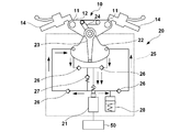
- FIG. 3 is a schematic view showing the configuration of the steering damper device 20.
- the steering damper device 20 is a device capable of variably generating a damping force acting on the rotational operation of the steering mechanism 10.
- the steering damper device 20 generates a damping force against the runout in order to reduce the so-called kickback (reaction) in which the steering wheel 14 suddenly swings when an external force acts on the front wheels 101 from the road surface during traveling.
- the steering damper device 20 is an electronically controlled steering damper, and the damping force can be variably controlled by controlling the driving current of the solenoid valve 21.
- the steering damper device 20 is a hydraulic rotary type in which a swingable vane 23 is arranged in a fan-shaped oil chamber 22 in a plan view, and the flow resistance of hydraulic oil in the oil chamber 22 generated when the vane 23 swings is used as a damping force. Is.
- a top bridge 12 is connected to the base of the vane 23 via a link mechanism 24.
- the steering damper device 20 includes a hydraulic control circuit 25.
- the hydraulic control circuit 25 includes a solenoid valve 21.
- the solenoid valve 21 is driven by the control unit 50 described later.
- the control unit 50 changes the opening area of the valve by driving the solenoid valve 21, and changes the flow resistance of the hydraulic oil. That is, the control unit 50 controls the damping force generated by the steering damper device 20 by controlling the drive current of the solenoid valve 21.
- the hydraulic control circuit 25 includes a check valve 26, a relief valve 27, and an accumulator 28.
- the solid line arrow in the figure indicates the flow of hydraulic oil when the steering mechanism 10 is steered to the left.
- the dotted arrow in the figure indicates the flow of hydraulic oil when the steering mechanism 10 is steered to the right.
- the configuration of the steering damper device 20 is an example, and other well-known configurations can be adopted.
- the steering damper device 20 may be a cylinder type.
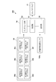
- FIG. 4 is a block diagram showing an example of a control configuration of the vehicle 100.
- FIG. 4 mainly shows a configuration required in relation to the present embodiment described later.
- the vehicle 100 includes a control unit 50 composed of an ECU (Electric Control Unit) and the like.
- the control unit 50 includes a processing unit 51, a storage unit 52 such as RAM and ROM, and an I / F unit 53 (interface unit) that relays transmission / reception of signals between an external device and the processing unit 51.
- the processing unit 51 is a processor typified by a CPU, and executes a program stored in the storage unit 52.
- the storage unit 52 stores data and the like used by the processing unit 51 for processing.
- control unit 50 controls the damping force of the steering damper device 20. Furthermore, the control unit 50 controls the damping force of the steering damper device 20 at the time of turning braking of the vehicle 100.
- the control unit 50 may be configured to include a plurality of ECUs (Electric Control Units), each of which may be provided with a processor, a storage device, and an external I / F.
- the control unit 50 may include a drive control ECU that controls the drive of the power unit 104 and a damping force control ECU that controls the damping force of the steering damper device 20.
- the number of ECUs and the functions in charge of each ECU can be appropriately designed, and can be subdivided or integrated from the above example.
- the vehicle 100 includes a front wheel rotation speed sensor 101a that detects the rotation speed of the front wheels 101.
- the inertial measurement unit (IMU) 30 is a sensor unit that detects the behavior of the vehicle 100, and is arranged near the center of gravity of the vehicle 1, for example.
- the IMU 30 detects the acceleration sensors 30a to 30c for detecting the acceleration in the front-rear direction, the left-right direction, and the up-down direction of the vehicle 100, and the angular accelerations in the roll direction, pitch direction, and yaw direction of the vehicle 100.
- Each acceleration sensor 30c to 30f is included.
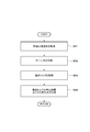
- FIG. 5 is an example of damping force control of the steering damper device 20 at the time of turning braking, which is executed by the control unit 50.
- the magnitude of the damping force at the start of this process is set to an initial value, and this initial value can be appropriately set based on the configuration of the vehicle 100, the steering damper device 20, and the like.
- control unit 50 acquires the amount of change ⁇ Trq / ⁇ t of the steering torque Trq per unit time. Details will be described later (see FIG. 6).
- the control unit 50 acquires the deceleration a (m / s2) of the front wheel 101. For example, the control unit 50 acquires the deceleration a based on the detection result of the front wheel rotation speed sensor 101a. As an example, the control unit 50 acquires the deceleration a by calculating (in other words, differentiating) the amount of change in the rotation speed of the front wheels 101 per unit time detected by the front wheel rotation speed sensor 101a.
- the control unit 50 executes the damping force control of the steering damper device 20.
- the control unit 50 determines the damping force based on the change amount ⁇ Trq / ⁇ t acquired in S1 and the deceleration a acquired in S2, and the steering damper device 20 so that the steering damper device 20 generates the damping force. Controls the damping force of. That is, the control unit 50 controls the damping force based on the values of the amount of change ⁇ Trq / ⁇ t acquired in S1 and the deceleration a acquired in S2, and the like. In the present embodiment, the control unit 50 controls the drive current of the solenoid valve 21 so that the steering damper device 20 generates a target damping force. Details will be described later (see FIG. 7).
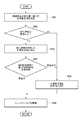
- FIG. 6 is a flowchart showing a detailed example of the acquisition process of the steering torque Trq in S1 of FIG.
- the control unit 50 acquires the deceleration a of the front wheel 101.
- the control unit 50 acquires the deceleration a by, for example, the same process as the process of S2.
- the control unit 50 acquires the bank angle (roll angle) ⁇ of the vehicle 100.
- the control unit 50 acquires the bank angle ⁇ by integrating the detection results (roll angular velocity) of each acceleration sensor 30d in the roll direction.
- the control unit 50 acquires the steering torque Trq.
- the control unit 50 estimates the steering torque Trq based on the deceleration a acquired in S11 and the bank angle ⁇ acquired in S12.
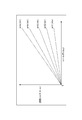
- FIG. 8 is a diagram showing an example of a table showing the relationship between the deceleration a and the bank angle ⁇ of the front wheels 101 and the estimated value of the steering torque Trq.
- the control unit 50 refers to this table and estimates the steering torque Trq based on the deceleration a and the bank angle ⁇ .
- the estimated value of the steering torque Trq is set so as to increase as the roll angle (bank angle) increases. Further, in the case of the present embodiment, there is a magnitude relationship of A5> A4> A3> A2> A1 with respect to the deceleration, and the estimated value of the steering torque Trq is set so as to increase as the deceleration a increases.
- control unit 50 can grasp the braking state of the vehicle 100 by the deceleration a and the turning state of the vehicle by the bank angle. Therefore, it can be said that the control unit 50 estimates the steering torque Trq according to the vehicle state at the time of turning braking by estimating the steering torque Trq based on the deceleration a and the bank angle ⁇ .
- the control unit 50 may calculate the steering torque Trq based on various parameters.
- the control unit 50 may calculate the steering torque Trq based on parameters such as vehicle weight, deceleration a, roll angle ⁇ , front wheel shared load, and lateral movement amount of the ground contact point.
- the control unit 50 acquires the amount of change ⁇ Trq / ⁇ t of the steering torque Trq per unit time.
- the control unit 50 acquires the amount of change ⁇ Trq / ⁇ t based on the steering torque Trq acquired in S13.
- the control unit 50 stores the value of the steering torque Trq acquired at the time of the previous processing, and divides the amount of change in the steering torque from the previous processing to the current processing by the control cycle to change the amount ⁇ Trq / ⁇ t. Is calculated.
- the control unit 50 may calculate the amount of change from a predetermined initial value or output 0 as the amount of change.
- FIG. 7 is a flowchart showing a detailed example of the damping force control process of S3 of FIG.
- the control unit 50 sets the target current value I of the solenoid valve 21 for generating the target damping force based on the change amount ⁇ Trq / ⁇ t acquired in S1 and the deceleration a acquired in S2.
- the control unit 50 may set the target current value I so that the damping force increases as the amount of change ⁇ Trq / ⁇ t increases. If the damping force is made too large when the amount of change ⁇ Trq / ⁇ t is small, the rider may feel uncomfortable, which may affect the riding feeling. On the other hand, when the amount of change ⁇ Trq / ⁇ t is large, the rider may not be able to cope with a sudden cut in the steering mechanism during turning. Therefore, the control unit 50 may set the target current value I so that the damping force increases as the amount of change ⁇ Trq / ⁇ t increases.
- control unit 50 may set the target current value I so that the damping force increases as the deceleration a increases. It is considered that the larger the deceleration a is, the easier it is for the vehicle 100 to slip. By controlling the damping force based on the deceleration a, the occurrence of slip can be suppressed.
- control unit 50 may control the damping force (that is, set the target current value I) based on the product of the amount of change ⁇ Trq / ⁇ t and the deceleration a. Slip during turning braking is likely to occur when the deceleration a is large and the amount of change ⁇ Trq / ⁇ t is large.
- the damping force can be controlled according to the ease of slipping, and the occurrence of slipping of the vehicle 100 can be further suppressed. Can be done.
- the control unit 50 confirms whether or not the traveling speed of the vehicle 100 is equal to or higher than the threshold value.
- the control unit 50 proceeds to S33 when the traveling speed is equal to or higher than the threshold value, and proceeds to the process of S35 when the traveling speed is less than the threshold value.
- the control unit 50 acquires the traveling speed of the vehicle 100 based on the detection result of the front wheel rotation speed sensor 101a, and confirms whether or not the traveling speed is equal to or higher than the threshold value.
- the control unit 50 sets the target current value I in consideration of the traveling speed of the vehicle 100.
- the control unit 50 may set the target current value I so as to suppress the increase in the damping force as the vehicle body speed of the vehicle 100 increases.
- the damping force is determined based on the damping force a, the damping force becomes larger than necessary. It may end up. Therefore, as the vehicle body speed of the vehicle 100 is increased, the increase in the damping force is suppressed, so that the runout of the steering mechanism 10 can be suppressed more effectively according to the vehicle speed.
- control unit may determine the target current value I with the traveling speed added based on the table showing the relationship between the target current value I set in S31 and the target current value I with the traveling speed added. Further, for example, the control unit 50 may determine the target current value I by multiplying the target current value I set in S31 by a coefficient corresponding to the traveling speed.
- the control unit 50 determines whether or not the damping force control can be performed based on the detection result of the IMU 30.
- the control unit 50 proceeds to the process of S36 when it is determined that the control can be executed, and proceeds to the process of S35 when it is determined that the control cannot be executed.
- the control unit 50 makes an erroneous determination regarding the deceleration a due to an erroneous detection or failure of the front wheel rotation speed sensor 101a. In this case, it is conceivable that the control unit 50 increases the damping force in an unnecessary situation.
- control unit 50 suppresses the influence of unnecessary control intervention on the riding feeling by increasing the damping force only when the vehicle 100 is actually decelerated based on the detection result of the IMU 30. be able to.
- control unit 50 may determine whether or not control can be performed based on the detection result of the acceleration sensor 30a in the front-rear direction.
- the control unit 50 sets the target current value I as the initial value. That is, when the traveling speed of the vehicle 100 does not reach the threshold value or when the IMU 30 cannot detect that the vehicle 100 is actually decelerating, the target current value I is set as the initial value. As a result, unnecessary control intervention can be prevented and the rider's discomfort can be reduced.
- control unit 50 drives the solenoid valve 21 with the set target current value I. That is, the control unit 50 controls the damping force of the steering damper device 20 by driving the solenoid valve 21.
- the steering damper device 20 is based on the amount of change ⁇ Trq / ⁇ t of the steering torque Trq generated in the steering mechanism 10 per unit time and the deceleration a of the front wheels 101.
- the damping force is controlled. Therefore, it is possible to suppress the runout of the steering mechanism 10 according to the vehicle state at the time of turning braking. Furthermore, since the damping force is controlled more effectively according to the vehicle body condition, the vibration of the steering mechanism 10 during turning braking is suppressed while reducing the discomfort felt by the rider due to the unnecessary increase in damping force. be able to.
- the control unit 50 may reduce the target current value I at a constant rate when the target current value I decreases.
- the control unit 50 can also adopt a configuration in which a rate limit is applied to the downlink side when setting the target current value I of the solenoid valve 21.
- the runout of the steering mechanism 10 is suppressed by generating a damping force in response to a sudden rise in the steering torque Trq. Therefore, the responsiveness when the damping force is increased (at the time of rising) is important. However, if the damping force is reduced immediately when the high damping force is no longer necessary, the effect of the control may be weakened or the rider may feel uncomfortable. Therefore, by gradually reducing the generated damping force, it is possible to more effectively suppress the runout of the steering mechanism 10.
- the damping force control of the steering damper device 20 at the time of turning braking (for convenience, the damping force control at the time of turning braking) has been focused on.
- the control unit 50 may perform damping force control of the other steering damper device 20 in parallel according to the traveling state of the vehicle 100.
- the control unit 50 may execute damping force control (referred to as normal traveling damping force control for convenience) of the steering damper device 20 based on the vehicle body speed, acceleration, and the like.
- the control unit 50 may intervene in the damping force control during turning braking while controlling the damping force of the steering damper device 20 in accordance with the damping force control during normal running in normal running.
- the control unit 50 compares the target damping force based on the normal running damping force control with the target damping force based on the turning braking damping force control, and outputs the maximum value thereof as the final damping force output. May be.
- control unit 50 compares the target current value I of the solenoid valve 21 based on the damping force control during normal running with the target current value I of the solenoid valve 21 based on the damping force control during turning braking, and they are compared.
- the maximum value of may be selected.
- FIG. 9 is a block diagram showing an example of a control configuration of the vehicle 100 according to another embodiment.
- the present embodiment is different from the above embodiment in that the vehicle 100 includes a steering torque sensor 10a.
- the same components as those in the above embodiment will be designated by the same reference numerals and the description thereof will be omitted.
- the steering torque sensor 10a detects the torque generated in the steering mechanism 10.
- a well-known configuration such as a magnetostrictive type torque sensor or a strain gauge type torque sensor can be adopted.
- FIG. 10 is a flowchart showing an example of damping force control of the steering damper device 20 according to another embodiment, and details of the process of S1 of FIG. 5 when the steering torque is acquired based on the detection result of the steering torque sensor 10a. An example is shown.
- the control unit 50 acquires the steering torque Trq based on the detection result of the steering torque sensor 10a.
- S112 is the same as the process of S14 of FIG. According to this embodiment, the steering torque Trq generated in the steering mechanism 10 can be directly acquired as an actually measured value instead of an estimated value.
- the power unit 104 is an engine, but a configuration including an electric motor as the power unit 104 or a configuration including both an internal combustion engine and an electric motor can be adopted. That is, the vehicle 100 may be an electric vehicle or a hybrid vehicle.
- the saddle-mounted vehicle (1) of the above embodiment is Steering mechanism (10) that steers the front wheels and A steering damper device (20) capable of variably generating a damping force acting on the rotational operation of the steering mechanism, and a steering damper device (20).
- a control means (50) for controlling the damping force of the steering damper device is provided. The control means controls the damping force based on the amount of change in the steering torque generated in the steering mechanism per unit time and the deceleration of the front wheels (S1, S2, S3).
- the damping force is controlled based on the amount of change in the steering torque generated in the steering mechanism per unit time and the deceleration of the front wheels, so that the vehicle state at the time of turning braking can be obtained. Therefore, it is possible to suppress the runout of the steering mechanism at the time of turning braking.
- control means controls the damping force so that the damping force increases as the amount of change increases (S31).
- control means controls the damping force so that the damping force increases as the deceleration increases (S31).
- the damping force becomes large in a state where the deceleration is large, which makes it easy for the vehicle to slip, so that the occurrence of slip can be suppressed more effectively.
- control means controls the damping force based on the product of the change amount and the deceleration (S31).
- the damping force is controlled according to the likelihood of slip occurrence during turning braking, so that slip occurrence can be suppressed more effectively.
- control means estimates the steering torque based on the roll angle of the saddle-type vehicle and the deceleration of the front wheels (S11, S12, S13).
- the steering torque can be estimated according to the vehicle state at the time of turning braking.
- a torque sensor (10a) for detecting the magnitude of the steering torque generated in the steering mechanism is further provided.
- the control means acquires the steering torque based on the detection result of the torque sensor (S111).
- the magnitude of the steering torque can be directly acquired.
- the detection means (101a) for detecting the rotational speed of the front wheels is further provided.
- the control means acquires the deceleration of the front wheels based on the detection result of the detection means (S2, S11).
- the deceleration of the front wheels can be obtained from the rotation speed of the front wheels.
- control means controls the damping force based on the change amount and the deceleration when the vehicle body speed of the saddle-type vehicle is equal to or higher than the threshold value (S32).
- the control means suppresses the increase of the damping force as the vehicle body speed of the saddle-type vehicle increases (S33).
- the control device (50) of the above embodiment is The steering damper device is applied to a saddle-type vehicle provided with a steering mechanism (10) for steering the front wheels and a steering damper device (20) capable of variably generating a damping force acting on the rotational operation of the steering mechanism. It is a control device (50) that controls the damping force of The damping force is controlled based on the amount of change in the steering torque generated in the steering mechanism per unit time and the deceleration of the front wheels (S1, S2, S3).
- the damping force is controlled based on the amount of change in the steering torque generated in the steering mechanism per unit time and the deceleration of the front wheels, so that the vehicle state at the time of turning braking can be obtained. Therefore, it is possible to suppress the runout of the steering mechanism at the time of turning braking.
Landscapes
- Engineering & Computer Science (AREA)
- Mechanical Engineering (AREA)
- General Engineering & Computer Science (AREA)
- Regulating Braking Force (AREA)
- Vehicle Body Suspensions (AREA)
Priority Applications (3)
| Application Number | Priority Date | Filing Date | Title |
|---|---|---|---|
| JP2021548809A JP7261895B2 (ja) | 2019-09-27 | 2020-09-14 | 鞍乗型車両及び制御装置 |
| DE112020004586.2T DE112020004586T5 (de) | 2019-09-27 | 2020-09-14 | Fahrzeug vom Grätschtyp und Steuervorrichtung |
| US17/702,951 US12139230B2 (en) | 2019-09-27 | 2022-03-24 | Straddle type vehicle and control unit for steering torque damping |
Applications Claiming Priority (2)
| Application Number | Priority Date | Filing Date | Title |
|---|---|---|---|
| JP2019177709 | 2019-09-27 | ||
| JP2019-177709 | 2019-09-27 |
Related Child Applications (1)
| Application Number | Title | Priority Date | Filing Date |
|---|---|---|---|
| US17/702,951 Continuation US12139230B2 (en) | 2019-09-27 | 2022-03-24 | Straddle type vehicle and control unit for steering torque damping |
Publications (1)
| Publication Number | Publication Date |
|---|---|
| WO2021060039A1 true WO2021060039A1 (ja) | 2021-04-01 |
Family
ID=75166921
Family Applications (1)
| Application Number | Title | Priority Date | Filing Date |
|---|---|---|---|
| PCT/JP2020/034632 Ceased WO2021060039A1 (ja) | 2019-09-27 | 2020-09-14 | 鞍乗型車両及び制御装置 |
Country Status (4)
| Country | Link |
|---|---|
| US (1) | US12139230B2 (https=) |
| JP (1) | JP7261895B2 (https=) |
| DE (1) | DE112020004586T5 (https=) |
| WO (1) | WO2021060039A1 (https=) |
Cited By (2)
| Publication number | Priority date | Publication date | Assignee | Title |
|---|---|---|---|---|
| JP2023048501A (ja) * | 2021-09-28 | 2023-04-07 | 本田技研工業株式会社 | 鞍乗り型車両 |
| US12139230B2 (en) | 2019-09-27 | 2024-11-12 | Honda Motor Co., Ltd. | Straddle type vehicle and control unit for steering torque damping |
Families Citing this family (4)
| Publication number | Priority date | Publication date | Assignee | Title |
|---|---|---|---|---|
| WO2021059856A1 (ja) * | 2019-09-27 | 2021-04-01 | 本田技研工業株式会社 | 鞍乗型車両及び制御装置 |
| JP7742387B2 (ja) * | 2023-10-06 | 2025-09-19 | ヤマハ発動機株式会社 | 二輪車両のステアリング制御システム |
| JP2025069711A (ja) * | 2023-10-18 | 2025-05-01 | ヤマハ発動機株式会社 | 鞍乗型車両 |
| JP2025069712A (ja) * | 2023-10-18 | 2025-05-01 | ヤマハ発動機株式会社 | 鞍乗型車両 |
Citations (4)
| Publication number | Priority date | Publication date | Assignee | Title |
|---|---|---|---|---|
| JP2009126432A (ja) * | 2007-11-27 | 2009-06-11 | Denso Corp | ステアリングダンパ制御装置及びステアリングダンパ制御システム |
| WO2013168422A1 (ja) * | 2012-05-09 | 2013-11-14 | ヤマハ発動機株式会社 | ステアリングダンパ制御装置及びそれを備えた鞍乗型車両 |
| JP2015514039A (ja) * | 2012-04-04 | 2015-05-18 | ロベルト・ボッシュ・ゲゼルシャフト・ミト・ベシュレンクテル・ハフツングRobert Bosch Gmbh | 二輪車のカーブ走行時の操舵トルクを低減する方法 |
| WO2017057514A1 (ja) * | 2015-09-30 | 2017-04-06 | 本田技研工業株式会社 | 自転車 |
Family Cites Families (6)
| Publication number | Priority date | Publication date | Assignee | Title |
|---|---|---|---|---|
| JP5064984B2 (ja) * | 2007-11-30 | 2012-10-31 | 本田技研工業株式会社 | 自動二輪車のステアリング補助システム |
| JP5255329B2 (ja) | 2008-06-04 | 2013-08-07 | ヤマハ発動機株式会社 | ステアリングダンパシステム及びそれを備えた鞍乗り型車両 |
| US10279857B2 (en) | 2015-03-30 | 2019-05-07 | Honda Motor Co., Ltd. | Vehicle driving force control device |
| US10953890B2 (en) * | 2016-10-19 | 2021-03-23 | Kawasaki Jukogyo Kabushiki Kaisha | Steering torque estimating device |
| JP7053339B2 (ja) | 2018-03-30 | 2022-04-12 | ダイハツ工業株式会社 | 故障診断装置 |
| WO2021060039A1 (ja) | 2019-09-27 | 2021-04-01 | 本田技研工業株式会社 | 鞍乗型車両及び制御装置 |
-
2020
- 2020-09-14 WO PCT/JP2020/034632 patent/WO2021060039A1/ja not_active Ceased
- 2020-09-14 JP JP2021548809A patent/JP7261895B2/ja active Active
- 2020-09-14 DE DE112020004586.2T patent/DE112020004586T5/de active Pending
-
2022
- 2022-03-24 US US17/702,951 patent/US12139230B2/en active Active
Patent Citations (4)
| Publication number | Priority date | Publication date | Assignee | Title |
|---|---|---|---|---|
| JP2009126432A (ja) * | 2007-11-27 | 2009-06-11 | Denso Corp | ステアリングダンパ制御装置及びステアリングダンパ制御システム |
| JP2015514039A (ja) * | 2012-04-04 | 2015-05-18 | ロベルト・ボッシュ・ゲゼルシャフト・ミト・ベシュレンクテル・ハフツングRobert Bosch Gmbh | 二輪車のカーブ走行時の操舵トルクを低減する方法 |
| WO2013168422A1 (ja) * | 2012-05-09 | 2013-11-14 | ヤマハ発動機株式会社 | ステアリングダンパ制御装置及びそれを備えた鞍乗型車両 |
| WO2017057514A1 (ja) * | 2015-09-30 | 2017-04-06 | 本田技研工業株式会社 | 自転車 |
Cited By (3)
| Publication number | Priority date | Publication date | Assignee | Title |
|---|---|---|---|---|
| US12139230B2 (en) | 2019-09-27 | 2024-11-12 | Honda Motor Co., Ltd. | Straddle type vehicle and control unit for steering torque damping |
| JP2023048501A (ja) * | 2021-09-28 | 2023-04-07 | 本田技研工業株式会社 | 鞍乗り型車両 |
| JP7373532B2 (ja) | 2021-09-28 | 2023-11-02 | 本田技研工業株式会社 | 鞍乗り型車両 |
Also Published As
| Publication number | Publication date |
|---|---|
| JP7261895B2 (ja) | 2023-04-20 |
| US20220212746A1 (en) | 2022-07-07 |
| DE112020004586T5 (de) | 2022-06-09 |
| JPWO2021060039A1 (https=) | 2021-04-01 |
| US12139230B2 (en) | 2024-11-12 |
Similar Documents
| Publication | Publication Date | Title |
|---|---|---|
| JP7261895B2 (ja) | 鞍乗型車両及び制御装置 | |
| JP7014760B2 (ja) | 鞍乗り型車両の操舵アシスト装置 | |
| JP5715000B2 (ja) | 鞍乗り型の乗り物の制御装置および制御方法 | |
| JP5873143B2 (ja) | 鞍乗り型車両 | |
| JP6948157B2 (ja) | 車両制御装置 | |
| JP5540894B2 (ja) | 車両の制振制御装置 | |
| CN111527295B (zh) | 鞍乘型车辆 | |
| US11939025B2 (en) | Straddle type vehicle and control device | |
| JP2019119446A (ja) | 車両 | |
| JP6913072B2 (ja) | 車両運動制御装置 | |
| JP7198696B2 (ja) | 自動二輪車 | |
| EP3263416B1 (en) | Drive torque control device, drive source unit, and vehicle | |
| JP7169201B2 (ja) | リーン車両の制御装置及び転倒予測方法 | |
| JP5945571B2 (ja) | トラクション制御システムおよび鞍乗り型車両 | |
| WO2024203085A1 (ja) | 車両制御システム、及び鞍乗型車両 | |
| JP2021146943A (ja) | サスペンション制御装置 | |
| JP7373532B2 (ja) | 鞍乗り型車両 | |
| TW202136077A (zh) | 用於確定減震器壓縮速度的方法、電腦程式、控制單元以及二輪車 | |
| KR20130046253A (ko) | 드라이브 샤프트 보호장치 및 방법 | |
| JP2023048476A (ja) | 鞍乗り型車両 | |
| JP2020080591A (ja) | 電動車両 | |
| WO2023119740A1 (ja) | 鞍乗り型車両 | |
| JP2024066038A (ja) | 鞍乗型車両 | |
| WO2023119424A1 (ja) | 傾斜車両 | |
| WO2024236825A1 (ja) | 鞍乗型車両 |
Legal Events
| Date | Code | Title | Description |
|---|---|---|---|
| 121 | Ep: the epo has been informed by wipo that ep was designated in this application |
Ref document number: 20869430 Country of ref document: EP Kind code of ref document: A1 |
|
| ENP | Entry into the national phase |
Ref document number: 2021548809 Country of ref document: JP Kind code of ref document: A |
|
| 122 | Ep: pct application non-entry in european phase |
Ref document number: 20869430 Country of ref document: EP Kind code of ref document: A1 |