WO2021045197A1 - 燃料電池スタック、および燃料電池スタックの運転方法 - Google Patents
燃料電池スタック、および燃料電池スタックの運転方法 Download PDFInfo
- Publication number
- WO2021045197A1 WO2021045197A1 PCT/JP2020/033618 JP2020033618W WO2021045197A1 WO 2021045197 A1 WO2021045197 A1 WO 2021045197A1 JP 2020033618 W JP2020033618 W JP 2020033618W WO 2021045197 A1 WO2021045197 A1 WO 2021045197A1
- Authority
- WO
- WIPO (PCT)
- Prior art keywords
- flow path
- cooling water
- fuel
- pressure
- oxidant
- Prior art date
- Legal status (The legal status is an assumption and is not a legal conclusion. Google has not performed a legal analysis and makes no representation as to the accuracy of the status listed.)
- Ceased
Links
Images


Classifications
-
- H—ELECTRICITY
- H01—ELECTRIC ELEMENTS
- H01M—PROCESSES OR MEANS, e.g. BATTERIES, FOR THE DIRECT CONVERSION OF CHEMICAL ENERGY INTO ELECTRICAL ENERGY
- H01M8/00—Fuel cells; Manufacture thereof
- H01M8/02—Details
- H01M8/0202—Collectors; Separators, e.g. bipolar separators; Interconnectors
- H01M8/0267—Collectors; Separators, e.g. bipolar separators; Interconnectors having heating or cooling means, e.g. heaters or coolant flow channels
-
- H—ELECTRICITY
- H01—ELECTRIC ELEMENTS
- H01M—PROCESSES OR MEANS, e.g. BATTERIES, FOR THE DIRECT CONVERSION OF CHEMICAL ENERGY INTO ELECTRICAL ENERGY
- H01M8/00—Fuel cells; Manufacture thereof
- H01M8/02—Details
- H01M8/0202—Collectors; Separators, e.g. bipolar separators; Interconnectors
- H01M8/023—Porous and characterised by the material
-
- H—ELECTRICITY
- H01—ELECTRIC ELEMENTS
- H01M—PROCESSES OR MEANS, e.g. BATTERIES, FOR THE DIRECT CONVERSION OF CHEMICAL ENERGY INTO ELECTRICAL ENERGY
- H01M8/00—Fuel cells; Manufacture thereof
- H01M8/04—Auxiliary arrangements, e.g. for control of pressure or for circulation of fluids
- H01M8/04291—Arrangements for managing water in solid electrolyte fuel cell systems
-
- H—ELECTRICITY
- H01—ELECTRIC ELEMENTS
- H01M—PROCESSES OR MEANS, e.g. BATTERIES, FOR THE DIRECT CONVERSION OF CHEMICAL ENERGY INTO ELECTRICAL ENERGY
- H01M8/00—Fuel cells; Manufacture thereof
- H01M8/04—Auxiliary arrangements, e.g. for control of pressure or for circulation of fluids
- H01M8/04298—Processes for controlling fuel cells or fuel cell systems
- H01M8/04694—Processes for controlling fuel cells or fuel cell systems characterised by variables to be controlled
- H01M8/04746—Pressure; Flow
- H01M8/04768—Pressure; Flow of the coolant
-
- H—ELECTRICITY
- H01—ELECTRIC ELEMENTS
- H01M—PROCESSES OR MEANS, e.g. BATTERIES, FOR THE DIRECT CONVERSION OF CHEMICAL ENERGY INTO ELECTRICAL ENERGY
- H01M8/00—Fuel cells; Manufacture thereof
- H01M8/04—Auxiliary arrangements, e.g. for control of pressure or for circulation of fluids
- H01M8/04298—Processes for controlling fuel cells or fuel cell systems
- H01M8/04694—Processes for controlling fuel cells or fuel cell systems characterised by variables to be controlled
- H01M8/04746—Pressure; Flow
- H01M8/04783—Pressure differences, e.g. between anode and cathode
-
- H—ELECTRICITY
- H01—ELECTRIC ELEMENTS
- H01M—PROCESSES OR MEANS, e.g. BATTERIES, FOR THE DIRECT CONVERSION OF CHEMICAL ENERGY INTO ELECTRICAL ENERGY
- H01M8/00—Fuel cells; Manufacture thereof
- H01M8/24—Grouping of fuel cells, e.g. stacking of fuel cells
- H01M8/2465—Details of groupings of fuel cells
- H01M8/2483—Details of groupings of fuel cells characterised by internal manifolds
-
- Y—GENERAL TAGGING OF NEW TECHNOLOGICAL DEVELOPMENTS; GENERAL TAGGING OF CROSS-SECTIONAL TECHNOLOGIES SPANNING OVER SEVERAL SECTIONS OF THE IPC; TECHNICAL SUBJECTS COVERED BY FORMER USPC CROSS-REFERENCE ART COLLECTIONS [XRACs] AND DIGESTS
- Y02—TECHNOLOGIES OR APPLICATIONS FOR MITIGATION OR ADAPTATION AGAINST CLIMATE CHANGE
- Y02E—REDUCTION OF GREENHOUSE GAS [GHG] EMISSIONS, RELATED TO ENERGY GENERATION, TRANSMISSION OR DISTRIBUTION
- Y02E60/00—Enabling technologies; Technologies with a potential or indirect contribution to GHG emissions mitigation
- Y02E60/30—Hydrogen technology
- Y02E60/50—Fuel cells
Definitions
- An embodiment of the present invention relates to a fuel cell stack and a method of operating the fuel cell stack.
- the fuel cell stack is a power generation device that converts the chemical energy of the fuel into electrical energy by electrochemically reacting the fuel gas such as hydrogen with the oxidant gas such as air.
- fuel gas such as hydrogen
- oxidant gas such as air.
- types of fuel cells are known depending on the electrolyte, for example, solid oxide type, molten carbonate type, phosphoric acid type, and solid polymer type, and they are applied depending on the application due to the difference in operating conditions.
- the format is different.
- polymer electrolyte fuel cells have a low operating temperature, are easy to start and stop, and can have a high output density, so they are widely developed and put into practical use as power sources for automobiles, households, and even for business use. It is being advanced.
- the mainstream of polymer electrolyte fuel cells is the solid electrolyte membrane fuel cell that uses a proton (hydrogen ion) exchange type electrolyte membrane.
- a proton (hydrogen ion) exchange type electrolyte membrane In these electrolyte membranes, it is necessary to impregnate the electrolyte membrane in order to ensure the conductivity of protons, and the fuel gas and the oxidant gas are humidified and operated.
- As a method of humidifying the gas there are a method of providing a humidifying device outside the fuel cell stack (external humidification method) and a method of humidifying inside the battery stack (internal humidification method), but generally, the gas supplied to the cell laminate is used. If the flow rate is high, the humidity at the gas inlet of the laminated body decreases and the laminated body becomes dry. However, it is known that the deterioration of the electrolyte membrane constituting the fuel cell stack accelerates as the humidity and temperature increase.
- the operating temperature of polymer electrolyte fuel cells which are currently widely used, is below the boiling point of water, and humidification becomes excessive (oversaturated) with the consumption of reaction-generated water at the oxidant electrode and hydrogen at the fuel electrode.
- the carbon (carbon member) that constitutes the cell member reacts with water to become carbon dioxide and protons, and as a result, the carbon corrosion reaction is promoted. There is a risk of deterioration.
- An object to be solved by the present invention is to provide a fuel cell stack capable of suppressing deterioration due to drying of an electrolyte membrane and retention of condensed water, and a method for operating the fuel cell stack.
- the fuel electrode is arranged on one main surface and the oxidizing agent electrode is arranged on the main surface opposite to the main surface, and the fuel electrode side of the electrolyte film.
- the differential pressure between the fuel gas pressure at the inlet in the flow path and the cooling water pressure in the cooling water flow path corresponding to the inlet is the fuel gas pressure at the outlet in the fuel electrode flow path and the cooling water flow corresponding to the outlet.
- the differential pressure which is smaller than the differential pressure between the cooling water pressure and the cooling water pressure in the path and is larger than the maximum differential pressure between the cooling water pressure and the oxidant pressure and the maximum differential pressure between the cooling water pressure and the fuel electrode pressure, is the flow path. It is smaller than the capillary force of the board.
- the schematic diagram of the conventional fuel cell stack which shows the state which mounted the manifold on the side surface.
- FIG. 1 is a perspective view showing the structure of the fuel cell stack 1 with the manifold removed.
- the fuel cell stack 1 according to the embodiment is a structure that generates electricity by an electrochemical reaction in a fuel cell. That is, the fuel cell stack 1 includes a cell laminate 10, two current collector plates 20, a power terminal 20a, two insulating plates 30, two tightening plates 100, and a plurality of tie rods 200. It is composed.
- the tightening plate 100 has an end plate 110 and a beam portion 120.
- FIG. 1 shows a Z direction parallel to the stacking direction of the cell laminated body 10, and an X direction and a Y direction perpendicular to the Z direction and parallel to each other.
- the Z direction is the horizontal direction and is perpendicular to the gravity direction.
- the x and y planes are set as the bottom.
- Two current collector plates 20 are arranged on both sides of the cell laminate 10 in the stacking direction.
- the two current collector plates 20 are plate-shaped conductors and are arranged on both end faces of the cell laminate 10. Electric energy is extracted from the power terminal 20a provided on the current collector plate 20.
- the two insulating plates 30 are plate-shaped insulators, and are arranged between the two current collecting plates 20 and the two tightening plates 100, respectively. In this way, two current collector plates 20 and two insulating plates 30 are sequentially arranged on both sides of the cell laminated body 10 in the stacking direction, and these are integrally arranged from both sides in the stacking direction.
- FIG. 2 is a perspective view showing a basic configuration of the fuel cell 10a.
- the fuel cell 10a includes an electrolyte membrane 12, a first porous separator 14, and a second porous separator 16.
- a fuel electrode composed of a catalyst layer 31 and a gas diffusion layer 33 is formed on one main surface, and an oxidant electrode composed of a catalyst layer 32 and a gas diffusion layer 34 is formed on the other main surface.
- the electrolyte membrane 12 is, for example, a polymer type electrolyte membrane.
- the electrolyte membrane 12, the catalyst layer 31 and the catalyst 32 may be collectively referred to as a membrane electrode assembly.
- a plurality of the fuel cell 10a are laminated to form the cell laminated body 10.
- the fuel cell 10a according to the present embodiment corresponds to a unit cell.
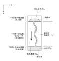
- FIG. 3 is a schematic view showing the flow of fuel gas on the main surface of the electrolyte membrane 12 on the fuel electrode side of the first porous separator 14.
- the first porous separator 14 is composed of a conductive porous plate having hydrophilic micropores.
- a fuel electrode flow path 140 along the fuel electrode is formed on the main surface 14a of the electrolyte membrane 12 on the fuel electrode side. Further, the fuel electrode flow path 140 has a first inlet portion 14b, a first outlet portion 14c, a second inlet portion 14d, and a second outlet portion 14e.
- the fuel electrode flow path 140 is the first fuel gas flow path connecting the first inlet portion 14b and the first outlet portion 14c, and the second fuel gas flow connecting the second inlet portion 14d and the second outlet portion 14e. Formed by the road.
- the fuel gas introduced from the first inlet portion 14b flows along the first fuel gas flow path of the fuel electrode flow path 140 and is discharged from the first outlet portion 14c.
- the fuel gas introduced from the second inlet portion 14d flows along the second fuel gas flow path of the fuel electrode flow path 140 and is discharged from the second outlet portion 14e.
- the hydrophilic micropores of the first porous separator 14 are water-containing, and the water-containing water can move through the network of micropores while preventing the permeation of fuel gas by the capillary force of the water in the hydrophilic micropores. It is supposed to be.
- FIG. 4 and 5 are views showing the configuration of the second porous separator 16, and FIG. 4 is a schematic view showing the flow of the oxidant gas on the main surface 16a of the second porous separator 16.
- FIG. I s a schematic view showing the flow of cooling water on the main surface 16b on the opposite side of the main surface 16a of the second porous separator 16.
- the second porous separator 16 is composed of a conductive porous plate having hydrophilic micropores.
- the second porous separator 16 forms an oxidant pole flow path 160a along the oxidant pole on the main surface 16a of the electrolyte membrane 12 on the oxidant pole side.
- the oxidant electrode flow path 160a has a first inlet portion 16c, a first outlet portion 16d, a second inlet portion 16e, and a second outlet portion 16f.
- the oxidant gas introduced from the first inlet portion 16c flows along the oxidant pole flow path 160a and is discharged from the first outlet portion 16d.
- the oxidant gas introduced from the second inlet portion 16e flows along the oxidant pole flow path 160a and is discharged from the second outlet portion 16f.
- the first porous separator 14 according to the present embodiment corresponds to the fuel extremely porous flow path plate
- the second porous separator 16 corresponds to the fuel extremely porous flow path plate.
- the hydrophilic pores of the second porous separator 16 are also moistened in the same manner as the first porous separator 14, and the network of micropores is prevented from permeating the oxidant gas by the capillary force of water in the hydrophilic micropores. It enables the movement of water contained through the water.
- a cooling water flow path 160b is formed on the main surface 16b on the side opposite to the oxidant electrode side.
- the cooling water flow path 160b has a first inlet portion 16g and a first outlet portion 16h.
- the cooling water introduced from the first inlet portion 16g flows along the cooling water flow path 160b and is discharged from the first outlet portion 16h.
- the pressure of the cooling water flowing through the cooling water flow path 160b is set to be lower than that of the fuel gas flowing through the fuel pole flow path 140 and the oxidant gas flowing through the oxidant pole flow path 160a.
- the cooling water in the cooling water flow path 160b communicates with the water contained in the hydrophilic fine pores in the first porous separator 14 and the hydrophilic fine pores in the second porous separator 16.
- the capillary force of the contained water prevents direct mixing of the fuel gas and the oxidant gas, and a network of micropores is provided in the humidification path of the oxidant gas and the fuel gas, in the oxidant gas flow path, and in the fuel gas flow path. It constitutes an absorption path for condensed water.
- a network of micropores is provided in the humidification path of the oxidant gas and the fuel gas, in the oxidant gas flow path, and in the fuel gas flow path. It constitutes an absorption path for condensed water.
- the pressure difference between the oxidant gas pressure and the cooling water and the pressure difference between the fuel gas pressure and the cooling water lower than the capillary force of the micropores, it is possible to stably hold the water in the hydrophilic pores. it can.
- FIG. 6 is a schematic view showing a condensed water absorption mechanism in the porous separator.
- the moving speed m w (mass flow rate) of the fluid inside the porous body such as the first porous separator 14 having hydrophilic fine pores is the permeation coefficient k [m2] of the porous separator and the water pressure. It can be described by Eq. (1) using the difference ⁇ P w [Pa], the density of water ⁇ w [kg / m3], and the viscosity coefficient of water ⁇ w [Pa ⁇ s].
- Pressure difference [Delta] P w is the pressure difference between the gas pressure P G [Pa] and the coolant pressure P W [Pa].
- the capillary length L is equivalent to the distance from the cooling water flow path (cooling water groove) 160b to the fuel electrode flow path (gas groove) 140. Therefore, the transmission coefficient k and thickness, the physical properties of water are certain conditions, the pressure difference between the pressure Pw and the gas pressure P G, i.e., absorption rate as the pressure and differential pressure of the cooling water pressure of the gas side is large Becomes larger.
- FIG. 6 shows one typical pore for the sake of simplicity.
- the actual separator has a complicated structure in which innumerable pores are connected in a network shape.
- FIG. 7 is a schematic view showing a gas inlet humidification mechanism in the porous separator.
- the humidification rate mv on the surface of the first porous separator 14 is the evaporation rate of water from the gas-liquid interface formed at the pore end near the fuel electrode flow path 140 to the gas side.
- the upper limit of the evaporation rate of water is defined by the transport rate of water due to the capillary force from the cooling water flow path 160b to the vicinity of the fuel electrode flow path 140.
- the water transport rate in FIG. 7 also follows the equation (1), but the difference from FIG.
- ⁇ P is the driving pressure difference ⁇ P is the pressure Pws in the capillary tube on the gas-liquid interface water side near the surface of the gas flow path and the cooling water flow path 160b. It is a pressure difference from the pressure Pw.
- the Pws is the gas pressure P G (3) have a relationship of equation further (3) micropore representative radius rc in equation water permeability coefficient K of the separator (4) since there is a relation of formula (2)
- ⁇ W is the density of water [kg / m 3 ]
- ⁇ W is the viscosity coefficient of water [Pa ⁇ s]
- ⁇ W is the viscosity coefficient of water [Pa ⁇ s]
- ⁇ is.
- the water contact angle [rad] with respect to the inner wall of the porous separator micropores rc is the representative radius [m] of the porous separator micropores, ⁇ is the porosity [-] of the porous separator, and K is porous. It is the permeation coefficient [m 2 ] of the quality separator, and L is the distance [m] from the gas flow path to the cooling water flow path.
- the main driving force of water transport is the capillary pressure
- P G -P W represents the ullage component of the driving force. Accordingly, P G -P W, i.e., more pressure difference between the fuel electrode channel 140 and the cooling water flow path 160b is as small as possible is desirable.
- FIG. 7 also shows one typical pore.
- the actual separator has a complicated structure in which innumerable pores are connected in a network, but the transmission coefficient is defined as the cross-sectional area of the representative passage of the entire pore group forming the network, and the representative pore radius is defined as the capillary characteristic. Equation (3) can be applied by shifting. Regarding the above, the relationship between the fuel pole flow path 140 and the cooling water flow path 160b has been described, but the same phenomenon occurs in the oxidant pole flow path 160a and the cooling water flow path 160b.
- the second porous separator 16 of the next fuel cell 10a is laminated in the Z direction of the first porous separator 14. Therefore, the first porous separator 14 is cooled by the cooling water in at least one of the cooling water flow paths 160b in the Z direction. Furthermore, the humidification of the fuel gas in the fuel electrode flow path 140 is affected by the cooling water pressure in the cooling water flow path 160b at the nearest neighbor position. That is, the humidification of the fuel gas progresses as the differential pressure between the fuel gas pressure in the fuel electrode flow path 140 and the cooling water pressure in the cooling water flow path 160b at the nearest position becomes smaller. On the contrary, as the differential pressure increases, the absorption of condensed water in the fuel electrode flow path 140 is promoted and the retention is suppressed.
- the humidification of the oxidant electrode flow path 160a to the oxidant gas is affected by the cooling water pressure in the cooling water flow path 160b at the nearest position. That is, as the difference pressure between the oxidant gas pressure in the oxidant electrode flow path 160a and the cooling water pressure in the cooling water flow path 160b at the nearest position becomes smaller, the humidification of the oxidant gas progresses further. On the contrary, as the differential pressure increases, the absorption of condensed water in the oxidant electrode flow path 160a is promoted and the retention is suppressed.
- the fuel gas is, for example, a hydrogen-containing gas.
- the fuel gas flows along the fuel electrode flow path 140 of the first porous separator 14 and causes a fuel electrode reaction.
- the oxidant gas is, for example, an oxygen-containing gas.
- the oxidant gas flows along the oxidant pole flow path 160a of the second porous separator 16 and causes an oxidant pole reaction.
- the fuel cell stack 1 utilizes these electrochemical reactions to extract electrical energy from the power terminal 20a provided on the current collector plate 20 (FIG. 1).
- FIG. 8 is a diagram showing a state in which the manifold is mounted on the side surface of the cell stack 10 of the fuel cell stack 1 along the stacking direction.
- the fuel cell stack 1 further includes a fuel electrode manifold 42, a fuel electrode facing manifold 44, a cooling water manifold 46, and a cooling water facing manifold 48.
- the fuel electrode manifold 42 is arranged on the first side surface of the fuel cell stack 1 along the stacking direction.
- the fuel electrode manifold 42 is discharged from the supply space 42b that supplies the fuel gas supplied from the fuel gas supply device to the fuel electrode flow path 140 in the fuel cell 10a by the first inlet portion 14b, and from the second outlet portion 14e. It is a manifold in which the discharge space 42a for further discharging the fuel gas is separated by a divider.
- the fuel electrode facing manifold 44 is arranged on the third side surface corresponding to the first side surface.
- the fuel electrode facing manifold 44 is a manifold that supplies the fuel gas discharged from the first outlet portion 14c of the fuel electrode flow path 140 to the fuel pole flow path 140 in the fuel cell 10a from the second inlet portion 14d.
- the cooling water manifold 46 has a first cooling water manifold 46a, a first oxidant pole manifold 46b, and a second oxidant pole manifold 46c.
- the cooling water manifold 46 is adjacent to the first side surface and is arranged on the second side surface along the stacking direction of the fuel cell stack 1.
- the first cooling water manifold 46a is a manifold that supplies cooling water to the cooling water flow path 160b in the fuel cell 10a via the first inlet portion 16g.
- the first oxidant pole manifold 46b supplies the oxidant gas supplied from the oxidant gas supply device to the oxidant pole flow path 160a in the fuel cell 10a by the first inlet portion 16c.
- the second oxidant electrode manifold 46c further discharges the fuel gas discharged from the second outlet portion 16f.
- the first oxidant pole manifold 46b and the second oxidant pole manifold 46c are separated by a divider.
- the cooling water facing manifold 48 has a first cooling water facing manifold 48a and an oxidizing agent pole facing manifold 48b.
- the cooling water facing manifold 48 faces the second side surface and is arranged on the fourth side surface along the stacking direction of the fuel cell 10a.
- the first cooling water facing manifold 48a is a manifold having a discharge space for further discharging the cooling water discharged from the first outlet portion 16h.
- the oxidant pole facing manifold 48b is a manifold that supplies the oxygen-containing gas discharged from the first outlet portion 16d to the oxidant pole flow path 160a in the fuel cell 10a from the second inlet portion 16e.
- the first fuel gas flow path connecting the first inlet portion 14b and the first outlet portion 14c is arranged vertically above the region on the upstream side of the cooling water flow path 160b, and is arranged with the second inlet portion 14d.
- the second fuel gas flow path connecting the second outlet portion 14e is arranged vertically above the region on the downstream side of the cooling water flow path 160b.
- the cooling water pressure in the cooling water flow path 160b decreases as it goes downstream.
- the fuel gas in the fuel electrode flow path 140 decreases as it goes downstream.
- the differential pressure between the inlet portion 16g and the outlet portion 16h of the cooling water flow path 160b is larger than the differential pressure between the first inlet portion 14b and the first outlet portion 14c of the fuel electrode flow path 140.
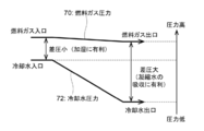
- FIG. 9 is a diagram showing a differential pressure between the fuel gas in the fuel pole flow path 140 and the cooling water pressure in the cooling water flow path at a position corresponding to the fuel pole flow path 140.
- the vertical axis shows the pressure.
- the line 70 shows the pressure of the fuel gas at a position along the fuel pole flow path 140 from the first inlet portion 14b to the second outlet portion 14e of the fuel pole flow path 140.
- Line 72 indicates the cooling water pressure in the cooling water flow path 160b corresponding to the position along the fuel pole flow path 140. That is, the cooling water pressure in the cooling water flow path 160b corresponding to the position along the fuel pole flow path 140 is the cooling water pressure at the position in the cooling water flow path 160b at the shortest distance from each position along the fuel pole flow path 140. Is. More specifically, it indicates the cooling water pressure in the cooling water flow path 160b at a position vertically below or above each position.
- the differential pressure between the fuel gas pressure and the cooling water pressure from the upstream to the downstream of the fuel electrode flow path 140 is the fuel electrode. It is smaller than the differential pressure between the fuel gas pressure of the second outlet portion 14e in the flow path 140 and the cooling water pressure in the cooling water flow path 160b at a position vertically below or above the second outlet portion 14e. If there is no cooling water flow path 160b directly below or above, the differential pressure is obtained using the cooling water pressure in the cooling water flow path 160b in the vicinity thereof.
- the first porous separator 14 and the second porous separator 16 are composed of a conductive porous plate having micropores, the smaller the difference pressure between the fuel gas pressure and the cooling water pressure, the smaller the pressure difference between the fuel gas pressure and the cooling water pressure.
- the water content that infiltrates the first porous separator 14 via the second porous separator 16 and the electrolyte membrane 12 increases.
- the first inlet portion 14b in the fuel electrode flow path 140 is more likely to humidify the fuel gas than the second outlet portion 14e. Therefore, it is possible to suppress the drying and high temperature of the electrolyte membrane 12.
- the second outlet portion 14e is more likely to absorb the condensed water generated in the fuel electrode flow path 140 than the first inlet portion 14b. That is, since the differential pressure becomes larger toward the downstream side of the fuel electrode flow path 140, carbon corrosion and characteristic deterioration due to the pool of water in the fuel electrode flow path 140 can be further suppressed toward the downstream side.
- the humidification of the fuel gas progresses further at the first inlet portion 14b, and the first At the 2 outlet portion 14e, there is an effect that the absorption of condensed water is further promoted.
- the first inlet portion 14b has the effect of further humidifying the fuel gas
- the second outlet portion 14e has the effect of further promoting the absorption of condensed water.
- FIG. 10 is a schematic showing the differential pressure between the oxidant gas and the cooling water pressure at the first inlet portion 16c of the oxidant pole flow path 160a and the differential pressure between the oxidant gas and the cooling water pressure at the second outlet portion 16f. It is a figure. The vertical axis shows the pressure. The first inlet portion 16c is arranged on the upstream side of the cooling water flow path 160b with respect to the second outlet portion 16f. As a result, the differential pressure between the oxidant gas pressure of the first inlet portion 16c and the cooling water pressure in the cooling water flow path 160b at the position vertically below the first inlet portion 16c is the oxidant gas of the second outlet portion 16f. It is smaller than the differential pressure between the pressure and the cooling water pressure in the cooling water flow path 160b at a position vertically below the second outlet portion 16f.
- the first porous separator 14 is composed of a conductive porous plate having fine pores as described above, the smaller the differential pressure between the oxidant gas and the cooling water pressure, the more the first porous separator 14 is infiltrated. Increases the amount of water used. As a result, the first inlet portion 16c in the oxidant pole flow path 160 is more likely to humidify the oxidant gas than the second outlet portion 16f. Therefore, it is possible to suppress the drying and high temperature of the electrolyte membrane 12.
- FIG. 11 is a schematic view of a conventional fuel cell stack showing a state in which a manifold is mounted on a side surface of the fuel cell stack 1 along the stacking direction of the fuel cell.
- the positions of the first inlet portion 14b and the second outlet portion 14e of the fuel electrode flow path 140 are opposite to those of the fuel cell stack 1 according to the present embodiment. It has become.
- the positions of the first inlet portion 16c and the second outlet portion 16f of the oxidant pole flow path 160a are opposite to those of the fuel cell stack 1 according to the present embodiment. ..
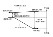
- FIG. 12 is a diagram showing a differential pressure between the fuel gas pressure in the fuel electrode flow path 140 in the conventional fuel cell stack and the cooling water pressure in the cooling water flow path at the position corresponding to the fuel electrode flow path 140.
- the vertical axis shows the pressure.
- the line 74 shows the pressure of the fuel gas at a position along the fuel pole flow path 140 from the first inlet portion 14b to the second outlet portion 14e of the fuel pole flow path 140.
- the line 72 shows the cooling water pressure in the cooling water flow path 160b at a position vertically below the position along the fuel pole flow path 140.
- the positions of the first inlet portion 14d and the second outlet portion 14e of the fuel pole flow path 140 are opposite to those of the fuel cell stack 1 according to the present embodiment. Therefore, the differential pressure between the fuel gas pressure of the first inlet portion 14b and the cooling water pressure in the cooling water flow path 160b at a position vertically below or above the first inlet portion 14b is the second pressure in the fuel electrode flow path 140. It is larger than the differential pressure between the fuel gas pressure of the outlet portion 14e and the cooling water pressure in the cooling water flow path 160b at a position vertically below or above the second outlet portion 14e. Therefore, the drying of the first inlet portion 14b proceeds from the second outlet portion 14e. Further, the absorption of the condensed water in the second outlet portion 14e is suppressed from that in the first inlet portion 14b.
- the positions of the first inlet portion 16c and the second outlet portion 16f of the oxidant pole flow path 160a are opposite to those of the fuel cell stack 1 according to the present embodiment.
- the differential pressure between the oxidant gas pressure of the first inlet portion 16c and the cooling water pressure in the cooling water flow path 160b at a position vertically below the first inlet portion 16c is the oxidant gas of the second outlet portion 16f. It is larger than the differential pressure between the pressure and the cooling water pressure in the cooling water flow path 160b at a position vertically below the second outlet portion 16f. Therefore, the drying of the first inlet portion 16c proceeds from the second outlet portion 16f. Further, the absorption of the condensed water in the second outlet portion 16f is suppressed from that in the first inlet portion 16c.
- the conventional fuel cell stack 4 has an effect contrary to the effect obtained by the fuel cell stack 1 according to the present application.
- the differential pressure between the fuel gas pressure of the first inlet portion 14b in the fuel pole flow path 140 and the cooling water pressure in the cooling water flow path 160b corresponding to the first inlet portion 14b. Is set to be smaller than the differential pressure between the fuel gas pressure of the second outlet portion 14e in the fuel electrode flow path 140 and the cooling water pressure in the cooling water flow path 160b corresponding to the second outlet portion 14e.
- the first inlet portion 14b has the effect of further humidifying the fuel gas
- the second outlet portion 14e has the effect of further promoting the absorption of condensed water.
- the fuel gas can be more humidified at the first inlet portion 14b, deterioration due to drying of the electrolyte membrane 12 is suppressed, and the differential pressure increases as the distance approaches the second outlet portion 14e, so that the condensed water stays. Can be further suppressed.
- first fuel gas flow path connecting the first inlet portion 14b and the first outlet portion 14c is arranged vertically above or below the region on the upstream side of the cooling water flow path 160b, and the second inlet portion 14d and the second outlet are arranged.
- the second fuel gas flow path connecting the portion 14e was arranged vertically above or below the region on the downstream side of the cooling water flow path 160b. Therefore, it is possible to increase the differential pressure between the fuel gas pressure and the cooling water pressure from the upstream to the downstream of the fuel electrode flow path 140, and the fuel gas is further humidified at the first inlet portion 14b.
- the second outlet portion 14e has the effect of further advancing the absorption of condensed water.
- the oxidant pole flow path 160a is formed in the first porous separator 14 and the fuel pole flow path 140 is formed in the first porous separator 16. It is different from the fuel cell stack 1 according to the first embodiment. Hereinafter, the differences from the fuel cell stack 1 according to the first embodiment will be described.
- the electrolyte membrane 12 differs from the first embodiment in that an oxidant electrode is formed on the main surface on the vertically upper side and a fuel electrode is formed on the other main surface.
- FIG. 13 is a schematic view showing the main surface shape of the electrolyte membrane 12 on the oxidizing agent pole side of the first porous separator 14.
- An oxidant pole flow path 160a along the oxidant pole is formed on the main surface 16a of the electrolyte membrane 12 on the oxidant pole side.
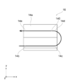
- FIG. 14 is a diagram showing the shape of the main surface 14a of the second porous separator 16, and as shown in FIG. 14, the fuel pole flow along the fuel electrode on the main surface 14a on the fuel electrode side of the electrolyte membrane 12. It forms a road 140.
- the oxidant pole flow path 160a is formed in the first porous separator 14 and the fuel pole flow path 140 is formed in the second porous separator 16, it is equivalent to FIG. 8 when viewed from above vertically. It is possible to obtain the arrangement of.
- the first porous separator 14 according to the present embodiment corresponds to the fuel extremely porous flow path plate
- the second porous separator 16 corresponds to the fuel extremely porous flow path plate.
- the first fuel gas flow path connecting the first inlet portion 14b and the first outlet portion 14c is arranged vertically above or below the region on the upstream side of the cooling water flow path 160b.
- the second fuel gas flow path connecting the second inlet portion 14d and the second outlet portion 14e is arranged vertically above or below the region on the downstream side of the cooling water flow path 160b. Therefore, it is possible to increase the differential pressure between the fuel gas pressure and the cooling water pressure from the upstream to the downstream of the fuel electrode flow path 140, and the fuel gas is further humidified at the first inlet portion 14b.
- the second outlet portion 14e has the effect of further advancing the absorption of condensed water.
- FIG. 15 is a diagram showing a state in which the manifold is mounted on the side surface of the fuel cell stack 1 according to the second modification along the stacking direction of the fuel cell.
- the direction of the fuel gas flowing through the fuel pole flow path 140 is reversed with respect to the fuel cell stack 1 according to the first embodiment, and the direction of the oxidant gas flowing through the oxidant pole flow path 160a is reversed. Is reversed, and the direction of the cooling water flowing in the cooling water flow path 160b is reversed.
- the direction of the fuel gas flowing through the fuel electrode flow path 140 is changed with respect to the fuel cell stack 1 according to the first embodiment by changing the operation method of the fuel cell stack 1.
- the direction of the oxidant gas flowing through the oxidant electrode flow path 160a was reversed, and the direction of the cooling water flowing through the cooling water flow path 160b was reversed.
- the difference pressure between the fuel gas pressure of the first inlet portion 14b in the fuel pole flow path 140 and the cooling water pressure in the cooling water flow path 160b corresponding to the first inlet portion 14b is set as the fuel pole flow.
- the first inlet portion 14b has the effect of further humidifying the fuel gas
- the second outlet portion 14e has the effect of further promoting the absorption of condensed water.
- the fuel gas can be humidified at the first inlet portion 14b, deterioration due to drying of the electrolyte membrane 12 is suppressed, and the differential pressure increases as the distance approaches the second outlet portion 14e, so that the retention of condensed water can be suppressed. ..
- the first fuel gas flow path connecting the first inlet portion 14b and the first outlet portion 14c is arranged vertically above the region on the upstream side of the cooling water flow path 160b.
- the second fuel gas flow path connecting the second inlet portion 14d and the second outlet portion 14e can be arranged vertically above the region on the downstream side of the cooling water flow path 160b.
- the differential pressure between the fuel gas pressure and the cooling water pressure can be increased from the upstream to the downstream of the fuel electrode flow path 140, and the fuel gas is further humidified at the first inlet portion 14b.
- the second outlet portion 14e has the effect of further advancing the absorption of condensed water.
Landscapes
- Life Sciences & Earth Sciences (AREA)
- Engineering & Computer Science (AREA)
- Manufacturing & Machinery (AREA)
- Sustainable Development (AREA)
- Sustainable Energy (AREA)
- Chemical & Material Sciences (AREA)
- Chemical Kinetics & Catalysis (AREA)
- Electrochemistry (AREA)
- General Chemical & Material Sciences (AREA)
- Fuel Cell (AREA)
Priority Applications (5)
| Application Number | Priority Date | Filing Date | Title |
|---|---|---|---|
| CN202080059634.8A CN114270582B (zh) | 2019-09-05 | 2020-09-04 | 燃料电池组及燃料电池组的运转方法 |
| JP2021544054A JP7183435B2 (ja) | 2019-09-05 | 2020-09-04 | 燃料電池スタック、および燃料電池スタックの運転方法 |
| CA3148862A CA3148862C (en) | 2019-09-05 | 2020-09-04 | Fuel cell stack and operation method for fuel cell stack |
| DE112020004227.8T DE112020004227T5 (de) | 2019-09-05 | 2020-09-04 | Brennstoffzellenstapel und Verfahren zum Betrieb eines Brennstoffzellenstapels |
| US17/586,500 US11831059B2 (en) | 2019-09-05 | 2022-01-27 | Fuel cell stack and operation method for fuel cell stack |
Applications Claiming Priority (2)
| Application Number | Priority Date | Filing Date | Title |
|---|---|---|---|
| JP2019-162198 | 2019-09-05 | ||
| JP2019162198 | 2019-09-05 |
Related Child Applications (1)
| Application Number | Title | Priority Date | Filing Date |
|---|---|---|---|
| US17/586,500 Continuation US11831059B2 (en) | 2019-09-05 | 2022-01-27 | Fuel cell stack and operation method for fuel cell stack |
Publications (1)
| Publication Number | Publication Date |
|---|---|
| WO2021045197A1 true WO2021045197A1 (ja) | 2021-03-11 |
Family
ID=74853273
Family Applications (1)
| Application Number | Title | Priority Date | Filing Date |
|---|---|---|---|
| PCT/JP2020/033618 Ceased WO2021045197A1 (ja) | 2019-09-05 | 2020-09-04 | 燃料電池スタック、および燃料電池スタックの運転方法 |
Country Status (6)
| Country | Link |
|---|---|
| US (1) | US11831059B2 (https=) |
| JP (1) | JP7183435B2 (https=) |
| CN (1) | CN114270582B (https=) |
| CA (1) | CA3148862C (https=) |
| DE (1) | DE112020004227T5 (https=) |
| WO (1) | WO2021045197A1 (https=) |
Citations (2)
| Publication number | Priority date | Publication date | Assignee | Title |
|---|---|---|---|---|
| JP2005158596A (ja) * | 2003-11-27 | 2005-06-16 | Nissan Motor Co Ltd | 燃料電池システム |
| JP2013191433A (ja) * | 2012-03-14 | 2013-09-26 | Toshiba Corp | 燃料電池スタックおよび燃料電池システム |
Family Cites Families (6)
| Publication number | Priority date | Publication date | Assignee | Title |
|---|---|---|---|---|
| JP2002025584A (ja) | 2000-07-04 | 2002-01-25 | Fuji Electric Co Ltd | 固体高分子電解質型燃料電池とその加湿方法 |
| US6746982B2 (en) | 2001-12-27 | 2004-06-08 | Utc Fuel Cells, Llc | Porous carbon body for a fuel cell having an electronically conductive hydrophilic agent |
| CN100517831C (zh) * | 2003-06-24 | 2009-07-22 | 松下电器产业株式会社 | 高分子电解质型燃料电池 |
| JP5556434B2 (ja) * | 2009-06-26 | 2014-07-23 | 日産自動車株式会社 | ガス拡散電極およびその製造方法、ならびに膜電極接合体およびその製造方法 |
| JP6690503B2 (ja) * | 2016-11-09 | 2020-04-28 | トヨタ自動車株式会社 | 燃料電池単セル |
| KR102750642B1 (ko) * | 2018-12-26 | 2025-01-06 | 현대자동차주식회사 | 막-전극 접합체의 제조 방법 및 그로부터 제조된 막-전극 접합체 |
-
2020
- 2020-09-04 DE DE112020004227.8T patent/DE112020004227T5/de active Pending
- 2020-09-04 CN CN202080059634.8A patent/CN114270582B/zh active Active
- 2020-09-04 WO PCT/JP2020/033618 patent/WO2021045197A1/ja not_active Ceased
- 2020-09-04 CA CA3148862A patent/CA3148862C/en active Active
- 2020-09-04 JP JP2021544054A patent/JP7183435B2/ja active Active
-
2022
- 2022-01-27 US US17/586,500 patent/US11831059B2/en active Active
Patent Citations (2)
| Publication number | Priority date | Publication date | Assignee | Title |
|---|---|---|---|---|
| JP2005158596A (ja) * | 2003-11-27 | 2005-06-16 | Nissan Motor Co Ltd | 燃料電池システム |
| JP2013191433A (ja) * | 2012-03-14 | 2013-09-26 | Toshiba Corp | 燃料電池スタックおよび燃料電池システム |
Also Published As
| Publication number | Publication date |
|---|---|
| JPWO2021045197A1 (https=) | 2021-03-11 |
| US11831059B2 (en) | 2023-11-28 |
| US20220158219A1 (en) | 2022-05-19 |
| JP7183435B2 (ja) | 2022-12-05 |
| CA3148862A1 (en) | 2021-03-11 |
| CN114270582A (zh) | 2022-04-01 |
| DE112020004227T5 (de) | 2022-05-19 |
| CN114270582B (zh) | 2024-09-13 |
| CA3148862C (en) | 2023-12-05 |
Similar Documents
| Publication | Publication Date | Title |
|---|---|---|
| JP6660472B2 (ja) | 燃料電池システム用の一体型水分離器を備えた加湿器、それを備えた燃料電池システムおよび乗り物 | |
| JP2703824B2 (ja) | 電気化学燃料電池の除水方法 | |
| KR100528340B1 (ko) | 액체연료 혼합장치 및 이를 적용한 직접액체연료 전지 | |
| JP4180404B2 (ja) | 燃料電池、酸化剤配流板 | |
| JP2000208156A (ja) | 固体高分子型燃料電池システム | |
| JP2002373677A (ja) | 燃料電池 | |
| JP2001176529A (ja) | 固体高分子型燃料電池本体および固体高分子型燃料電池発電システム | |
| JP6628342B2 (ja) | バイポーラプレートを有する燃料電池スタック、および燃料電池システム | |
| KR20190086392A (ko) | 연료전지용 기체확산층, 이를 포함하는 막-전극 접합체, 이를 포함하는 연료 전지 및 연료전지용 기체확산층의 제조방법 | |
| JP7183435B2 (ja) | 燃料電池スタック、および燃料電池スタックの運転方法 | |
| US20040115500A1 (en) | Polymer electrolyte fuel cell and power-generating system with polymer electrolyte fuel cells | |
| CN100392902C (zh) | 可使进入反应的氢气或空气温度与湿度稳定的燃料电池 | |
| JP2004529458A (ja) | 燃料電池の水分平衡を改良する方法 | |
| JP2005135763A (ja) | 燃料電池および燃料電池用セパレータ | |
| JP5193435B2 (ja) | 固体高分子電解質型燃料電池 | |
| JP4739880B2 (ja) | 固体高分子形燃料電池 | |
| JP2001185169A (ja) | 固体高分子型燃料電池 | |
| JP4738979B2 (ja) | 固体高分子型燃料電池スタック | |
| JP7614791B2 (ja) | 燃料電池スタック | |
| JP2005228580A (ja) | 燃料電池用電解質材及び燃料電池 | |
| JP2007005330A (ja) | 固体高分子型燃料電池システム | |
| JP5194379B2 (ja) | 固体高分子形燃料電池及びセパレータ | |
| JP2004152516A (ja) | 固体高分子型燃料電池 | |
| CN101473470A (zh) | 使用水合的非全氟化碳氢化合物离子交换膜的燃料电池 | |
| JP2008159444A (ja) | 燃料電池スタック及び燃料電池用セパレータ |
Legal Events
| Date | Code | Title | Description |
|---|---|---|---|
| 121 | Ep: the epo has been informed by wipo that ep was designated in this application |
Ref document number: 20861743 Country of ref document: EP Kind code of ref document: A1 |
|
| ENP | Entry into the national phase |
Ref document number: 3148862 Country of ref document: CA |
|
| ENP | Entry into the national phase |
Ref document number: 2021544054 Country of ref document: JP Kind code of ref document: A |
|
| 122 | Ep: pct application non-entry in european phase |
Ref document number: 20861743 Country of ref document: EP Kind code of ref document: A1 |