WO2021044919A1 - 1,3-ブタジエンの製造方法 - Google Patents
1,3-ブタジエンの製造方法 Download PDFInfo
- Publication number
- WO2021044919A1 WO2021044919A1 PCT/JP2020/032167 JP2020032167W WO2021044919A1 WO 2021044919 A1 WO2021044919 A1 WO 2021044919A1 JP 2020032167 W JP2020032167 W JP 2020032167W WO 2021044919 A1 WO2021044919 A1 WO 2021044919A1
- Authority
- WO
- WIPO (PCT)
- Prior art keywords
- gas
- butadiene
- tower
- solvent
- volume
- Prior art date
- Legal status (The legal status is an assumption and is not a legal conclusion. Google has not performed a legal analysis and makes no representation as to the accuracy of the status listed.)
- Ceased
Links
Images


Classifications
-
- C—CHEMISTRY; METALLURGY
- C07—ORGANIC CHEMISTRY
- C07C—ACYCLIC OR CARBOCYCLIC COMPOUNDS
- C07C5/00—Preparation of hydrocarbons from hydrocarbons containing the same number of carbon atoms
- C07C5/42—Preparation of hydrocarbons from hydrocarbons containing the same number of carbon atoms by dehydrogenation with a hydrogen acceptor
- C07C5/48—Preparation of hydrocarbons from hydrocarbons containing the same number of carbon atoms by dehydrogenation with a hydrogen acceptor with oxygen as an acceptor
-
- C—CHEMISTRY; METALLURGY
- C07—ORGANIC CHEMISTRY
- C07B—GENERAL METHODS OF ORGANIC CHEMISTRY; APPARATUS THEREFOR
- C07B61/00—Other general methods
-
- C—CHEMISTRY; METALLURGY
- C07—ORGANIC CHEMISTRY
- C07C—ACYCLIC OR CARBOCYCLIC COMPOUNDS
- C07C7/00—Purification; Separation; Use of additives
- C07C7/005—Processes comprising at least two steps in series
-
- C—CHEMISTRY; METALLURGY
- C07—ORGANIC CHEMISTRY
- C07C—ACYCLIC OR CARBOCYCLIC COMPOUNDS
- C07C7/00—Purification; Separation; Use of additives
- C07C7/11—Purification; Separation; Use of additives by absorption, i.e. purification or separation of gaseous hydrocarbons with the aid of liquids
-
- C—CHEMISTRY; METALLURGY
- C07—ORGANIC CHEMISTRY
- C07C—ACYCLIC OR CARBOCYCLIC COMPOUNDS
- C07C2523/00—Catalysts comprising metals or metal oxides or hydroxides, not provided for in group C07C2521/00
- C07C2523/02—Catalysts comprising metals or metal oxides or hydroxides, not provided for in group C07C2521/00 of the alkali- or alkaline earth metals or beryllium
- C07C2523/04—Alkali metals
-
- C—CHEMISTRY; METALLURGY
- C07—ORGANIC CHEMISTRY
- C07C—ACYCLIC OR CARBOCYCLIC COMPOUNDS
- C07C2523/00—Catalysts comprising metals or metal oxides or hydroxides, not provided for in group C07C2521/00
- C07C2523/16—Catalysts comprising metals or metal oxides or hydroxides, not provided for in group C07C2521/00 of arsenic, antimony, bismuth, vanadium, niobium, tantalum, polonium, chromium, molybdenum, tungsten, manganese, technetium or rhenium
- C07C2523/18—Arsenic, antimony or bismuth
-
- C—CHEMISTRY; METALLURGY
- C07—ORGANIC CHEMISTRY
- C07C—ACYCLIC OR CARBOCYCLIC COMPOUNDS
- C07C2523/00—Catalysts comprising metals or metal oxides or hydroxides, not provided for in group C07C2521/00
- C07C2523/16—Catalysts comprising metals or metal oxides or hydroxides, not provided for in group C07C2521/00 of arsenic, antimony, bismuth, vanadium, niobium, tantalum, polonium, chromium, molybdenum, tungsten, manganese, technetium or rhenium
- C07C2523/24—Chromium, molybdenum or tungsten
- C07C2523/28—Molybdenum
-
- C—CHEMISTRY; METALLURGY
- C07—ORGANIC CHEMISTRY
- C07C—ACYCLIC OR CARBOCYCLIC COMPOUNDS
- C07C2523/00—Catalysts comprising metals or metal oxides or hydroxides, not provided for in group C07C2521/00
- C07C2523/16—Catalysts comprising metals or metal oxides or hydroxides, not provided for in group C07C2521/00 of arsenic, antimony, bismuth, vanadium, niobium, tantalum, polonium, chromium, molybdenum, tungsten, manganese, technetium or rhenium
- C07C2523/24—Chromium, molybdenum or tungsten
- C07C2523/31—Chromium, molybdenum or tungsten combined with bismuth
-
- C—CHEMISTRY; METALLURGY
- C07—ORGANIC CHEMISTRY
- C07C—ACYCLIC OR CARBOCYCLIC COMPOUNDS
- C07C2523/00—Catalysts comprising metals or metal oxides or hydroxides, not provided for in group C07C2521/00
- C07C2523/70—Catalysts comprising metals or metal oxides or hydroxides, not provided for in group C07C2521/00 of the iron group metals or copper
- C07C2523/74—Iron group metals
- C07C2523/745—Iron
-
- C—CHEMISTRY; METALLURGY
- C07—ORGANIC CHEMISTRY
- C07C—ACYCLIC OR CARBOCYCLIC COMPOUNDS
- C07C2523/00—Catalysts comprising metals or metal oxides or hydroxides, not provided for in group C07C2521/00
- C07C2523/70—Catalysts comprising metals or metal oxides or hydroxides, not provided for in group C07C2521/00 of the iron group metals or copper
- C07C2523/74—Iron group metals
- C07C2523/75—Cobalt
-
- C—CHEMISTRY; METALLURGY
- C07—ORGANIC CHEMISTRY
- C07C—ACYCLIC OR CARBOCYCLIC COMPOUNDS
- C07C2523/00—Catalysts comprising metals or metal oxides or hydroxides, not provided for in group C07C2521/00
- C07C2523/70—Catalysts comprising metals or metal oxides or hydroxides, not provided for in group C07C2521/00 of the iron group metals or copper
- C07C2523/74—Iron group metals
- C07C2523/755—Nickel
-
- C—CHEMISTRY; METALLURGY
- C07—ORGANIC CHEMISTRY
- C07C—ACYCLIC OR CARBOCYCLIC COMPOUNDS
- C07C2523/00—Catalysts comprising metals or metal oxides or hydroxides, not provided for in group C07C2521/00
- C07C2523/70—Catalysts comprising metals or metal oxides or hydroxides, not provided for in group C07C2521/00 of the iron group metals or copper
- C07C2523/76—Catalysts comprising metals or metal oxides or hydroxides, not provided for in group C07C2521/00 of the iron group metals or copper combined with metals, oxides or hydroxides provided for in groups C07C2523/02 - C07C2523/36
- C07C2523/84—Catalysts comprising metals or metal oxides or hydroxides, not provided for in group C07C2521/00 of the iron group metals or copper combined with metals, oxides or hydroxides provided for in groups C07C2523/02 - C07C2523/36 with arsenic, antimony, bismuth, vanadium, niobium, tantalum, polonium, chromium, molybdenum, tungsten, manganese, technetium or rhenium
- C07C2523/85—Chromium, molybdenum or tungsten
- C07C2523/88—Molybdenum
- C07C2523/887—Molybdenum containing in addition other metals, oxides or hydroxides provided for in groups C07C2523/02 - C07C2523/36
Definitions
- the present invention relates to a method for producing 1,3-butadiene, and more particularly to a method for producing 1,3-butadiene using an oxidative dehydrogenation reaction.
- C4 fraction a fraction having 4 carbon atoms obtained by cracking naphtha
- a method is adopted in which components other than butadiene are separated by distillation.
- Demand for butadiene is increasing as a raw material for synthetic rubber, etc., but the supply of C4 fraction is decreasing due to the shift of ethylene production method from naphtha cracking method to ethane thermal decomposition method. Therefore, there is a demand for the production of butadiene using the C4 fraction as a raw material.
- This production method includes an oxidative dehydrogenation reaction step in which a raw material gas containing n-butene and a molecular oxygen-containing gas containing molecular oxygen (specifically, for example, air) is subjected to an oxidative dehydrogenation reaction. It has a cooling step of cooling the produced gas obtained by the step, and a produced gas separating step of separating butadiene from the produced gas cooled by this step.
- a quenching tower including, for example, a filling tower or a shelf column, which quenches the generated gas by making it come into direct flow contact with the cooling medium, is used.
- reaction by-products such as carbonyl compounds such as acetaldehyde and methyl vinyl ketone and organic acids such as carboxylic acid are generated.
- reaction by-products are precipitated by, for example, quenching the product gas in the cooling step, and the solid component adheres to the solid packing or the shelf board (tray) in the quenching tower used. If the amount of the solid component adhered increases with time, a differential pressure is generated in the quenching tower, which makes it impossible to continue the cooling process. Therefore, it is necessary to decompose the quenching tower to remove the adhered solid component, and therefore, it is difficult to stably cool the produced gas for a long period of time.
- the present invention has been made based on the above circumstances, and an object of the present invention is to prevent or suppress the generation of solid components in the step of cooling the produced gas, and to cool the produced gas for a long period of time. It is an object of the present invention to provide a method for producing 1,3-butadiene that can be stably carried out over a period of time.
- the method for producing 1,3-butadiene of the present invention is a production gas containing 1,3-butadiene by oxidatively dehydrogenating oxygen with a raw material gas containing n-butene in the presence of a metal oxide catalyst.
- the step (C) of cooling the produced gas washed in the step (B) by contacting with a cooling medium, and the step (C) of cooling the produced gas cooled in the step (C) are selectively used as an absorption solvent.
- It has a step (D) of separating molecular oxygen and inert gases into other gases including 1,3-butadiene by absorption.
- the step (B) is characterized in that the generated gas is sprayed onto the surface of the cleaning liquid and brought into contact with the cleaning liquid to carry out the cleaning treatment.
- the step (B) is carried out in the cleaning unit, and the mass ratio of the cleaning liquid to the produced gas in the cleaning unit is 1.1 to 8. It is preferably 9.9.
- the cleaning unit has one or more stages of scrubbing portions for cleaning the produced gas.
- the pH of the cleaning liquid is in the range of 6 to 10 in the step (B).
- the cleaning liquid after the cleaning treatment of the produced gas in the step (B) is used as a cooling medium for cooling the produced gas in the step (C). Is preferable.
- the precipitated solid component is removed by cleaning the produced gas in the step (B) before subjecting the produced gas to the step (C) for cooling. Therefore, it is possible to prevent or suppress a large amount of solid components precipitated by cooling in the step (C) from adhering to the solid filling material, the shelf board, etc., and as a result, the cooling of the produced gas is stabilized for a long period of time. Can be executed.
- the method for producing butadiene (1,3-butadiene) of the present invention has the steps shown in (1) to (4) below, and by going through the steps (1) to (4) below.
- Butadiene is produced from a raw material gas containing n-butene.
- FIG. 1 is a flow chart showing an example of a specific method for carrying out the method for producing butadiene of the present invention.
- the butadiene production method of the example shown in FIG. 1 has the above steps (1) to (4) and absorbs other gases containing 1,3-butadiene obtained in the step (D).
- the absorption solvent used in the step (D) is circulated and used.
- a product gas containing butadiene (1,3-butadiene) is obtained by oxidatively dehydrogenating the raw material gas and the molecular oxygen-containing gas in the presence of a metal oxide catalyst.
- the oxidative dehydrogenation reaction between the raw material gas and the molecular oxygen-containing gas is carried out by the reactor 1 as shown in FIG.
- the reactor 1 is a tower-like structure in which a gas inlet and a gas outlet are provided in the upper part and a catalyst layer (not shown) is formed by filling the inside with a metal oxide catalyst. is there.
- the pipe 100 and the pipe 113 are connected to the gas introduction port via the pipe 116, and the pipe 101 is connected to the gas outlet of the cleaning unit 2.
- the step (A) will be specifically described.
- the reactor 1 is connected to the raw material gas and the molecular oxygen-containing gas via the pipe 100 communicating with the pipe 116, and if necessary, the inert gas and water (if necessary).
- Water vapor) (hereinafter collectively referred to as "new supply gas") is supplied.
- the new supply gas Before being introduced into the reactor 1, the new supply gas is heated to about 200 ° C. or higher and 400 ° C. or lower by a preheater (not shown) arranged between the reactor 1 and the pipe 100. Further, the reflux gas from the circulation step is supplied to the reactor 1 after being heated by the preheater via the pipe 113 communicating with the pipe 116 together with the new supply gas supplied through the pipe 100. Will be done.
- a mixed gas of the newly supplied gas and the reflux gas is supplied to the reactor 1 after being heated by the preheater.
- the new supply gas and the reflux gas may be directly supplied to the reactor 1 from separate pipes, but are supplied in a mixed state from the common pipe 116 as shown in FIG. It is preferable to be done.
- the common pipe 116 the mixed gas containing various components can be supplied to the reactor 1 in a state of being uniformly mixed in advance, so that the non-uniform mixed gas is partially contained in the reactor 1. It is possible to prevent the formation of explosive gas.
- butadiene (1,3-butadiene) is generated by the oxidative dehydrogenation reaction between the raw material gas and the molecular oxygen-containing gas, and the produced gas containing the butadiene is obtained. Be done.
- the obtained generated gas flows out to the pipe 101 from the gas outlet of the reactor 1.
- n-butene As the raw material gas, a gaseous substance obtained by gasifying n-butene, which is a monoolefin having 4 carbon atoms, with a vaporizer (not shown) is used. This raw material gas is a flammable gas.
- n-butene means linear butene, and specifically, 1-butene, cis-2-butene and trans-2-butene are included in n-butene.
- the raw material gas may contain arbitrary impurities. Specific examples of this impurity include branched monoolefins such as i-butene and saturated hydrocarbons such as propane, n-butane and i-butane.
- the raw material gas may contain 1,3-butadiene, which is a production target, as an impurity.
- the amount of impurities in the raw material gas is usually 60% by volume or less, preferably 40% by volume or less, more preferably 25% by volume or less, and particularly preferably 5% by volume or less in 100% by volume of the raw material gas.
- the reaction rate tends to be slowed down or the amount of by-products tends to increase due to the decrease in the concentration of linear butene in the raw material gas.
- a fraction containing linear butene as a main component obtained by separating butadiene and i-butene from a C4 fraction (fraction having 4 carbon atoms) produced as a by-product of naphtha decomposition.
- raffinate 2 a fraction containing linear butene as a main component
- C4 fraction fraction having 4 carbon atoms
- the butene fraction produced by the dehydrogenation reaction of n-butane or the oxidative dehydrogenation reaction can be used.
- Gases containing high-purity 1-butene, cis-2-butene and trans-2-butene, and mixtures thereof, obtained by dimerizing ethylene can also be used.
- Fluid Catalytic decomposes the heavy oil fraction obtained when crude oil is distilled in an oil refining plant or the like using a powdery solid catalyst in a fluidized bed state and converts it into hydrocarbons having a low boiling point.
- a gas containing a large amount of hydrocarbons having 4 carbon atoms obtained from Cracking) (hereinafter, may be abbreviated as “FCC-C4”) can be used as a raw material gas as it is, or from FCC-C4 to phosphorus or the like. It is also possible to use a raw material gas from which the impurities of the above have been removed.
- the molecular oxygen-containing gas is usually a gas containing 10% by volume or more of molecular oxygen (O 2). In this molecular oxygen-containing gas, the concentration of molecular oxygen is preferably 15% by volume or more, more preferably 20% by volume or more.
- the molecular oxygen-containing gas includes molecular oxygen (N 2 ), argon (Ar), neon (Ne), helium (He), carbon monoxide (CO), and carbon dioxide (CO 2 ). And may contain any gas such as water (water vapor).
- the amount of any gas in the molecular oxygen-containing gas is usually 90% by volume or less, preferably 85% by volume or less, and more preferably 80% by volume or less when the arbitrary gas is molecular nitrogen.
- any gas is a gas other than molecular nitrogen, it is usually 10% by volume or less, preferably 1% by volume or less. If the amount of the arbitrary gas is excessive, the required amount of molecular oxygen may not coexist with the raw material gas in the reaction system (inside the reactor 1). In the step (A), air is mentioned as a preferable specific example of the molecular oxygen-containing gas.
- the inert gases are preferably supplied to the reactor 1 together with the raw material gas and the molecular oxygen-containing gas.
- concentration (relative concentration) of the raw material gas and the molecular oxygen is adjusted so that the mixed gas does not form a roar in the reactor 1. can do.
- the inert gas include molecular nitrogen (N 2 ), argon (Ar) and carbon dioxide (CO 2 ). These can be used alone or in combination of two or more. Of these, molecular nitrogen is preferable from an economic point of view.
- Water is preferably supplied to the reactor 1 together with the raw material gas and the molecular oxygen-containing gas.
- the raw material gas and the molecular oxygen are used so that the mixed gas does not form a roar in the reactor 1 as in the case of the above-mentioned inert gases.
- the concentration (relative concentration) can be adjusted.
- the mixed gas contains a flammable raw material gas and molecular oxygen, its composition is adjusted so that the concentration of the raw material gas does not fall within the explosive range. Specifically, each gas constituting the mixed gas (specifically, a raw material gas, a molecular oxygen-containing gas (air), and an inert gas and water (water vapor) used as needed) is used.
- the gas of the reactor 1 is monitored by a flow meter (not shown) installed in a pipe (specifically, a pipe (not shown) communicating with the pipe 100 and a pipe 113) supplied to the reactor 1. Control the composition of the mixed gas at the inlet.
- the composition of the new supply gas supplied to the reactor 1 via the pipe 100 is controlled according to the molecular oxygen concentration of the reflux gas supplied to the reactor 1 via the pipe 113.
- the “explosion range” refers to a range in which the mixed gas has a composition that ignites in the presence of some ignition source.
- the concentration of flammable gas is lower than a certain value, it does not ignite even if an ignition source exists, and this concentration is called the lower explosive limit.
- the lower explosive limit is the lower limit of the explosion range.
- the explosive limit is the upper limit of the explosive range.
- the total concentration of 1-butene and 2-butene is 2% by volume or more and 30% by volume in 100% by volume of the mixed gas from the viewpoint of butadiene productivity and suppression of the burden on the metal oxide catalyst. It is preferably 5% by volume or less, more preferably 3% by volume or more and 25% by volume or less, and particularly preferably 5% by volume or more and 20% by volume or less. If the total concentration of 1-butene and 2-butene is too small, the productivity of butadiene may decrease. On the other hand, if the total concentration of 1-butene and 2-butene is excessive, the burden on the metal oxide catalyst may increase.
- the concentration (relative concentration) of molecular oxygen with respect to the raw material gas is preferably 50 parts by volume or more and 170 parts by volume or less, more preferably 70 parts by volume or more, with respect to 100 parts by volume of the raw material gas. It is 160 parts by volume or less.
- concentration of molecular oxygen in the mixed gas deviates from the above range, it tends to be difficult to adjust the concentration of molecular oxygen in the gas outlet of the reactor 1 by adjusting the reaction temperature. If the concentration of molecular oxygen in the gas outlet of the reactor 1 cannot be controlled by the reaction temperature, it becomes impossible to suppress the decomposition of the target product and the occurrence of side reactions inside the reactor 1. There is a risk.
- the concentration (relative concentration) of molecular nitrogen with respect to the raw material gas is preferably 400 parts by volume or more and 1800 parts by volume or less, more preferably 500 parts by volume or more, with respect to 100 parts by volume of the raw material gas. It is 1700 parts by volume or less.
- the concentration (relative concentration) of water (water vapor) with respect to the raw material gas is preferably 0 parts by volume or more and 900 parts by volume or less, more preferably 80 parts by volume or more and 300 parts by volume with respect to 100 parts by volume of the raw material gas. It is as follows.
- Metal oxide catalyst As the metal oxide catalyst, a composite oxide catalyst containing molybdenum and bismuth is used. As such a composite oxide catalyst, for example, one containing at least molybdenum (Mo), bismuth (Bi) and iron (Fe) can be used, and specific examples thereof include the following composition formula (1). Examples thereof include those containing a composite metal oxide represented by.
- Composition formula (1) Mo a Bi b F c X d Y e Z f O g
- X is at least one selected from the group consisting of Ni and Co.
- Y is at least one selected from the group consisting of Li, Na, K, Rb, Cs and Tl.
- Z is at least one selected from the group consisting of Mg, Ca, Ce, Zn, Cr, Sb, As, B, P and W.
- a, b, c, d, e, f and g each independently indicate the atomic ratio of each element, and when a is 12, b is 0.1 to 8 and c is 0.1 to 0.1. 20, d is 0 to 20, e is 0 to 4, f is 0 to 2, and g is the number of atoms of the oxygen element required to satisfy the valence of each of the above components. ..
- the composite oxide catalyst containing the composite metal oxide represented by the above composition formula (1) has high activity and high selectivity in a method for producing butadiene using an oxidative dehydrogenation reaction, and further has a long life. Excellent stability.
- the method for preparing the composite oxide catalyst is not particularly limited, and is an evaporative drying method, a spray-drying method, or oxidation using the raw material of each element related to the composite metal oxide constituting the composite oxide catalyst to be prepared.
- a known method such as a product mixing method can be adopted.
- the raw material of each of the above elements is not particularly limited, and for example, oxides, nitrates, carbonates, ammonium salts, hydroxides, carboxylates, ammonium carboxylates, ammonium halides, and hydrogen acids of the constituent elements. , Alkoxide and the like.
- the composite oxide catalyst may be used by supporting it on an inert carrier.
- the carrier type include silica, alumina, and silicon carbide.
- the supply amount of the mixed gas may be kept constant by reducing the supply amount of water (water vapor).
- the gas residence time in the piping and the reactor 1 can be kept constant, and fluctuations in the pressure of the reactor 1 can be suppressed.
- the pressure of the reactor 1 (specifically, the pressure at the gas inlet of the reactor 1), that is, the pressure in the step (A) is preferably 0.1 MPaG or more and 0.4 MPaG or less, and more preferably 0. It is 15 MPaG or more and 0.35 MPaG or less, and more preferably 0.2 MPaG or more and 0.3 MPaG or less.
- the gas hourly space velocity obtained by the following equation (1) is preferably at 500h -1 or more 5000h -1 or less, more preferably 800h -1 or more 3500H -1 or less, and more preferably not more than 1000h -1 or 3000h -1.
- the "catalyst layer volume” indicates the volume (apparent volume) of the entire catalyst layer including voids.
- the real volume gas spatiotemporal velocity (real volume GHSV) obtained by the following mathematical formula (2) is preferably 500 h -1 or more and 2300 h -1 or less, more preferably 600 h -1. above 2000h -1 or less, and more preferably not more than 700 h -1 or more 1500h -1.
- the reaction efficiency in the oxidative dehydrogenation reaction can be further improved.
- the "catalyst layer volume” indicates the volume (apparent volume) of the entire catalyst layer including voids, as in the above formula (1).
- the temperature of the reaction system rises, and a plurality of types of by-products can be produced.
- unsaturated carbonyl compounds having 3 to 4 carbon atoms such as acrolein, acrylic acid, methacrolein, methacrolein, maleic acid, fumaric acid, maleic anhydride, methyl vinyl ketone, crotonaldehyde and crotonic acid are used. When it is produced and the concentration in the produced gas is increased, various harmful effects occur.
- the unsaturated carbonyl compound dissolves in the absorbing solvent or the like that is circulated in the step (D), impurities are accumulated in the absorbing solvent or the like, and the precipitation of deposits on each member is likely to be induced. Become.
- the reaction temperature is preferably 300 ° C. or higher and 400 ° C. or lower, more preferably 320 ° C. or higher and lower than 380 ° C.
- the reaction temperature By setting the reaction temperature within the above range, caulking (precipitation of solid carbon) in the metal oxide catalyst can be suppressed, and the concentration of the unsaturated carbonyl compound in the produced gas can be kept within a certain range. It will be possible. Further, the concentration of molecular oxygen at the gas outlet of the reactor 1 can be kept within a certain range. On the other hand, if the reaction temperature is too low, the conversion rate of n-butene may decrease. Further, when the reaction temperature is excessive, the concentration of the unsaturated carbonyl compound becomes high, and impurities tend to accumulate in an absorption solvent or the like, or caulking in a metal oxide catalyst tends to occur.
- the reactor 1 is appropriately cooled by, for example, removing heat with a heat medium (specifically, dibenzyltoluene, nitrite, etc.).
- a heat medium specifically, dibenzyltoluene, nitrite, etc.
- the produced gas includes 1,3-butadiene, which is the target product of the oxidative dehydrogenation reaction between the raw material gas and the molecular oxygen-containing gas, as well as a reaction by-product, an unreacted raw material gas, and unreacted molecular oxygen. And gas for concentration adjustment etc. are included.
- Reaction by-products include carbonyl compounds and heterocyclic compounds.
- the carbonyl compound includes ketones, aldehydes and organic acids. Ketones include methyl vinyl ketone, acetophenone, benzophenone, anthraquinone and fluorenone.
- aldehydes include acetaldehyde, acrolein, methacrolein, crotonaldehyde, benzaldehyde and the like.
- organic acids include maleic acid, fumaric acid, acrylic acid, phthalic acid, benzoic acid, crotonic acid, tetrahydrophthalic acid, isophthalic acid, terephthalic acid, methacrylic acid, phenol and the like.
- a heterocyclic compound furan and the like can be mentioned.
- Step (B) the generated gas obtained in the step (A) is sprayed onto the surface of the cleaning liquid to bring it into contact with the cleaning liquid, thereby performing the cleaning treatment.
- the step (B) is preferably carried out in the cleaning unit 2 having one or more stages of scrubbing portions for cleaning the generated gas.
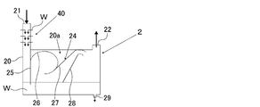
- FIG. 2 is an explanatory diagram showing a configuration of an example of a cleaning unit that can be used in the step (B).
- a scrubbing portion 20a is provided in a chamber 20 having a gas introduction port 21 for introducing the generated gas from the step (A) and a gas outlet 22 for leading out the generated gas that has been cleaned.
- the cleaning liquid W is stored in the bottom of the chamber 20, and the cleaning liquid outlet 29 for leading the cleaning liquid W to the outside is formed on the bottom wall of the chamber 20.
- the cleaning liquid outlet 29 is connected to the pipe 103.
- a flow path forming member 24 for forming a flow path for the generated gas is provided.
- the flow path forming member 24 is a vertical plate 25 provided so as to face the side wall of the chamber 20 and a first curved plate provided on the back surface of the vertical plate 25 and curved in a partially elliptical shape. It is composed of 26, a second curved plate 27 provided on the back surface of the first curved plate 26, and an auxiliary guide plate 28 provided so as to face the second curved plate 27.
- the lower end of the vertical plate 26 is provided so as to be immersed in the stored cleaning liquid W.
- a flow path is formed between the side wall of the chamber 20 and the vertical plate 25 to guide the generated gas introduced from the gas introduction port 21 to the stored cleaning liquid W. Further, between the second curved plate 27 and the auxiliary guide plate 28, a flow path is formed in which the road width becomes smaller from the upstream side to the downstream side.
- the gas generated from the step (a) is introduced into the scrubbing portion 20a from the gas introduction port 21.
- the introduced generated gas flows downward along the flow path between the vertical plate 25 and the side wall of the chamber 20 together with the cleaning liquid W sprayed from the cleaning liquid spraying unit 40. Then, when the generated gas is sprayed onto the liquid surface of the stored cleaning liquid W and comes into contact with the liquid surface, a part of the by-products in the produced gas is precipitated in the cleaning liquid W as a solid component.
- the flow speed of the generated gas is rapidly decelerated. And by slow reversal, droplets due to the cleaning liquid W are separated from the generated gas.
- the scrubbing unit 20a is subjected to the cleaning treatment of the generated gas, and then the gas is led out from the gas outlet 22 to the outside. Further, a part of the stored cleaning liquid W is led out from the cleaning liquid outlet 29 to the outside.
- water or alkaline water can be used as the cleaning liquid W.
- the temperature of the cleaning liquid W is preferably 5 ° C. or higher and 50 ° C. or lower, more preferably 5 ° C. or higher and 30 ° C. or lower.
- the cleaning liquid W led out from the cleaning liquid outlet 29 may be discarded, but it is preferably used as all or part of the cooling medium in the step (C) described later.
- the cleaning liquid W led out from the cleaning liquid outlet 29 is reused as a cooling medium in the step (C) by being supplied to the cooling medium supply mechanism 38 in the quenching tower 3 via the pipe 103. ..
- the mass ratio (cleaning liquid / generated gas) of the cleaning liquid W and the produced gas in the cleaning unit 2 is preferably 1.1 to 8.9. If this mass ratio is less than 1.1, the gas cleaning will be insufficient, and there is a risk that dirt will accumulate on the gas-liquid contact member 37 inside the quenching tower 3 in step () C described later. On the other hand, when this mass ratio exceeds 8.9, the balance between the cleaning liquid and the generated gas is lost, the cleaning mechanism due to the Venturi effect cannot be maintained, and the controllability of the cleaning unit 2 deteriorates. Dirt may also accumulate on the gas-liquid contact member 37 inside the quenching tower 3 in C).
- the pH of the cleaning liquid W is in the range of 6 to 10. If the pH of the cleaning liquid W is less than 6, the dirt cleaning effect of the cleaning liquid will not be exhibited, and there is a risk that dirt will accumulate on the gas-liquid contact member 37 inside the quenching tower 3 in step C described later. .. On the other hand, when the pH of the cleaning liquid W exceeds 10, there is a concern that alkaline corrosion may affect the equipment.
- the product gas washed in the step (B) is cooled.
- the cooling of the generated gas from the step (B) is performed by the quenching tower 3 and the cooling heat exchanger 4.
- the gas generated from the step (B) is supplied to the quenching tower 3 via the pipe 102, cooled in the quenching tower 3, and then cooled by the cooling heat exchanger 4 via the pipe 105. Is further cooled in the cooling heat exchanger 4.
- the produced gas from the step (A) is purified. Specifically, a part of the by-products contained in the produced gas from the step (A) is condensed or precipitated and removed by cooling.
- FIG. 3 is an explanatory diagram showing a configuration of an example of a quenching tower that can be used in the step (C).
- the quenching tower 3 is configured to quench the produced gas to a temperature of, for example, about 30 ° C. or higher and 90 ° C. or lower by bringing a cooling medium into countercurrent contact with the generated gas, and extends in the vertical direction at both ends. It has a closed cylindrical tower body 30.
- a gas introduction port 34 for introducing the gas generated from the step (B) into the inside of the tower main body 30 is provided at a position on the lower side of the peripheral wall portion 31 of the tower main body 30. Further, the tower top portion 32 of the tower body 30 is provided with a gas outlet 35 for leading out the cooled generated gas from the inside of the tower body 30. Further, the bottom 33 of the tower body 30 is provided with a cooling medium outlet 36 for leading out the cooling medium supplied to the inside.
- a gas-liquid contact member 37 is provided at a position between the gas introduction port 34 and the gas outlet 35 in the tower main body 30.
- a plurality of gas-liquid contact members 37 are arranged so as to be vertically overlapped with each other via a space.
- a cooling medium supply mechanism 38 for supplying a cooling medium for cooling the generated gas is provided above the gas-liquid contact member 37 on the uppermost stage.
- the quenching tower 3 when the quenching tower 3 is composed of a filling tower, an irregular filling can be used. Specific examples of irregular fillings include Raschig rings, pole rings, cascade mini rings, and the like. Further, when the quenching tower 3 is composed of a shelf column, a shelf board is used as the gas-liquid contact member 37.
- the cooling medium supply mechanism 38 has a spray head 39 for spraying the cooling medium.
- the spray head 39 is arranged above the gas-liquid contact member 37 at the uppermost stage in the tower body 30 so as to face downward.
- Water or alkaline water can be used as the cooling medium supplied from the cooling medium supply mechanism 38.
- the temperature of the cooling medium is appropriately determined according to the cooling temperature of the produced gas, but is preferably 10 ° C. or higher and 90 ° C. or lower, more preferably 20 ° C. or higher and 70 ° C. or lower, and particularly preferably 20 ° C. or higher. It is 40 ° C. or lower.
- a pipe 102 whose one end is connected to the gas outlet 22 of the reactor 1 is connected to the gas inlet 34 of the quenching tower 3, and a pipe 105 is connected to the gas outlet 35 of the quenching tower 3. .. Further, a pipe 103 is connected to the spray head 39 of the cooling medium supply mechanism 38 in the quenching tower 3, and a pipe 104 is connected to the cooling medium outlet 36 of the quenching tower 3.
- the internal temperature is preferably 10 ° C. or higher and 100 ° C. or lower, and more preferably 20 ° C. or higher and 90 ° C. or lower.
- the pressure of the quenching tower 3 during operation (specifically, the pressure of the gas outlet of the quenching tower 3), that is, the pressure of the step (C) is equal to the pressure of the step (A) or the pressure of the step (A). It is preferably less than the pressure.
- the difference between the pressure of the step (C) and the pressure of the step (A), that is, the value obtained by subtracting the pressure of the step (C) from the pressure of the step (A) is 0 MPaG or more and 0.05 MPaG or less. It is preferably 0.01 MPaG or more, and more preferably 0.04 MPaG or less.
- the reaction by-products in the gas produced from the step (A) can be condensed and dissolved in the cooling medium in the quenching tower 3. It can be promoted, and as a result, the concentration of the reaction by-product in the product gas flowing out from the quenching tower 3 can be further reduced.
- the generated gas is introduced into the tower body 30 from the gas introduction port 34 and is led out from the gas outlet 35.
- the generated gas is circulated from the lower part of the tower main body 30 to the upper part via the gas-liquid contact member 37 inside the tower main body 30.
- the cooling medium by the cooling water supply mechanism 38 is sprayed downward from the spray head 39.
- the supplied cooling medium is led out from the cooling medium outlet 36 to the outside of the tower body 30.
- the derived cooling medium may be discarded, but it may be used as the cleaning liquid W in the step (B).
- the cooling medium led out from the cooling medium outlet 36 is reused as the cleaning liquid W in the step (B) by being supplied to the cleaning liquid spraying unit 40 in the cleaning unit 2 via the pipe 104. ..
- a heat exchanger 4 capable of cooling the generated gas flowing out of the quenching tower 3 to room temperature (10 ° C. or higher and 30 ° C. or lower) is appropriately used.
- the cooling heat exchanger 4 is connected to the gas inlet with a pipe 105 having one end connected to the gas outlet 35 of the quenching tower 3, and is connected to the gas outlet of the heat exchanger 4.
- Piping 106 is connected.
- the pressure of the cooling heat exchanger 4 during operation is the pressure of the quenching tower 3 during operation (specifically, the pressure of the gas outlet of the quenching tower 3). Pressure) is preferably equal to.
- the concentration of molecular nitrogen is preferably 60% by volume or more and 94% by volume or less, more preferably. Is 70% by volume or more and 85% by volume or less.
- the concentration of butadiene is preferably 2% by volume or more and 15% by volume or less, more preferably 3% by volume or more and 10% by volume or less.
- the concentration of water (water vapor) is preferably 1% by volume or more and 30% by volume or less, and more preferably 1% by volume or more and 3% by volume or less.
- the concentration of ketones and aldehydes is preferably 0% by volume or more and 0.3% by volume or less, and more preferably 0.05% by volume or more and 0.25% by volume or less.
- the produced gas obtained through the step (C) is separated (coarse) into molecular oxygen and inert gases and other gases containing 1,3-butadiene by selective absorption into the absorbing solvent.
- the "other gas containing 1,3-butadiene” refers to at least butadiene and 1-butene and 2-butene (unreacted 1-butene and 2-butene) absorbed by the absorbing solvent. Indicates the gas contained.
- the separation of the produced gas through the step (C) is performed by the absorption tower 5 as shown in FIG.
- the absorption tower 5 is provided with a gas introduction port for introducing the gas produced through the step (C) at the lower part, a solvent introduction port for introducing the absorption solvent at the upper part, and the bottom of the tower is provided with a solvent introduction port.
- a solvent outlet is provided to derive an absorption solvent that has absorbed the gas (specifically, other gas containing 1,3-butadiene), and a gas that has not been absorbed by the absorption solvent (specifically) is provided at the top of the column.
- a pipe 106 having one end connected to the gas outlet of the heat exchanger 4 is connected to the gas inlet, a pipe 107 is connected to the solvent inlet, and a pipe 114 is connected to the solvent outlet.
- a pipe 108 is connected to the gas outlet of the absorption tower 5.
- the generated gas that has passed through the step (C), that is, the generated gas that has flowed out from the heat exchanger 4, is sent to the absorption tower 5 via the pipe 106, and is synchronously supplied to the absorption tower 5.
- the absorption solvent is supplied to the absorption tower 5 via the pipe 107.
- the absorbing solvent is countercurrently contacted with the produced gas that has undergone the step (C), and the other gas containing 1,3-butadiene in the produced gas that has undergone the step (C) is selectively absorbed by the absorbing solvent.
- the other gas containing 1,3-butadiene and the molecular oxygen and the inert gas are roughly separated.
- the absorption solvent that absorbed the other gas containing 1,3-butadiene flows out from the absorption tower 5 to the pipe 114, while the molecular oxygen and the inert gas that were not absorbed by the absorption solvent are absorbed. It flows out from the tower 5 to the pipe 108.
- the temperature inside the absorption tower 5 is not particularly limited, but as the temperature inside the absorption tower 5 increases, molecular oxygen and inert gases are less likely to be absorbed by the absorption solvent.
- the absorption efficiency of hydrocarbons such as butadiene (other gases containing 1,3-butadiene) into the absorption solvent increases, so that the productivity of butadiene increases.
- it is preferably 0 ° C. or higher and 60 ° C. or lower, and more preferably 10 ° C. or higher and 50 ° C. or lower.
- the pressure of the absorption tower 5 during operation (specifically, the pressure of the gas outlet of the absorption tower 5), that is, the pressure of the step (D) is equal to the pressure of the step (C) or the pressure of the step (C). It is preferably less than the pressure.
- the difference between the pressure of the step (D) and the pressure of the step (C), that is, the value obtained by subtracting the pressure of the step (D) from the pressure of the step (C) is 0 MPaG or more and 0.05 MPaG or less. It is preferably 0.01 MPaG or more, and more preferably 0.04 MPaG or less.
- the pressure difference between the step (C) and the step (D) within the above range, the absorption of butadiene (other gas containing 1,3-butadiene) into the absorption solvent in the absorption tower 5 can be promoted. As a result, the amount of the absorbing solvent used can be reduced, and the energy consumption can be reduced.
- the absorption solvent examples include those containing an organic solvent as a main component.
- “having an organic solvent as a main component” means that the content ratio of the organic solvent in the absorption solvent is 50% by mass or more.
- the organic solvent constituting the absorption solvent include aromatic compounds such as toluene, xylene and benzene, amide compounds such as dimethylformamide and N-methyl-2-pyrrolidone, sulfur compounds such as dimethyl sulfoxide and sulfolane, acetonitrile and butyronitrile and the like. Examples thereof include nitrile compounds, and ketone compounds such as cyclohexanone and acetophenone.
- the amount of the absorbing solvent used is not particularly limited, but is 10 times by mass with respect to the total flow rate (mass flow rate) of butadiene, 1-butene and 2-butene in the product gas produced through the step (C). It is preferably 100 times by mass or less, and more preferably 17 times by mass or more and 35 times by mass or less.
- the amount of the absorbing solvent used in the above range the absorption efficiency of other gases containing 1,3-butadiene can be improved.
- the amount of the absorbing solvent used is excessive, the amount of energy consumed for purification for circulating use of the absorbing solvent tends to increase. Further, when the amount of the absorbing solvent used is too small, the absorption efficiency of other gases containing 1,3-butadiene tends to decrease.
- the temperature of the absorbing solvent (temperature at the solvent inlet) is preferably 0 ° C. or higher and 60 ° C. or lower, and more preferably 0 ° C. or higher and 40 ° C. or lower.
- the molecular oxygen and the inert gas obtained in the step (D) are fed to the step (A) as a reflux gas.
- the molecular oxygen and the inert gas from the step (D) are processed by the solvent recovery column 6 and the compressor 7. Specifically, the molecular oxygen and the inert gas from the step (D), that is, the molecular oxygen and the inert gas flowing out from the absorption tower 5, are sent to the solvent recovery tower 6 via the pipe 108. After being fed and subjected to solvent removal treatment, it is fed to the compressor 7 via the pipe 111, and is pressure-adjusted if necessary.
- the molecular oxygen and the inert gas from the step (D) which has been subjected to the solvent removal treatment and the pressure adjustment treatment in this manner flow out from the compressor 7 toward the reaction tower 1 into the pipe 113.
- the molecular oxygen and the inert gas discharged from the solvent recovery tower 6 are partly transferred to the pipe 111 in the process of flowing through the pipe 111. It is discarded via the communicating pipe 112.
- the supply amount of the reflux gas for the step (A) is adjusted by providing the pipe 112 for discarding a part of the molecular oxygen and the inert gas flowing out from the solvent recovery tower 6. Can be done.
- the solvent recovery tower 6 is configured to remove the molecular oxygen and the inert gas from the solvent by washing the molecular oxygen and the inert gas from the step (D) with water or a solvent.
- a gas introduction port for introducing the molecular oxygen and the inert gas from the step (D) is provided in the central portion of the solvent recovery tower 6.
- a cleaning liquid inlet for introducing water or solvent is provided in the upper part of the solvent recovery tower 6.
- a pipe 108 whose one end is connected to the gas outlet of the absorption tower 5 is connected to the gas introduction port, and a pipe 109 is connected to the cleaning liquid introduction port.
- the solvent recovery tower 6 is provided at the top of the tower with a gas outlet for leading out molecular oxygen and inert gases washed with water or a solvent. Further, the bottom of the solvent recovery tower 6 is provided with a cleaning liquid outlet for leading out the water or solvent used for cleaning the molecular oxygen and the inert gas from the step (D).
- a pipe 111 is connected to the gas outlet of the solvent recovery tower 6, and a pipe 110 is connected to the cleaning liquid outlet.
- the absorption solvent contained in the molecular oxygen and the inert gas from the step (D) is removed, and the removed absorption solvent is washed together with the water or solvent used for washing.
- the liquid flows out from the liquid outlet to the pipe 110 and is collected through the pipe 110. Further, the molecular oxygen and the inert gas from the step (D) that have been subjected to the solvent removal treatment flow out to the pipe 111 from the gas outlet of the solvent recovery tower 6.
- the temperature inside the solvent recovery tower 6 is not particularly limited, but is preferably 0 ° C. or higher and 80 ° C. or lower, and more preferably 10 ° C. or higher and 60 ° C. or lower. ..
- compressor 7 a compressor capable of boosting the molecular oxygen and the inert gas from the solvent recovery column 6 as necessary to obtain the pressure required in the step (A) is appropriately used.
- the compressor 7 is connected to the gas inlet with a pipe 111 having one end connected to the gas outlet of the solvent recovery tower 6, and the compressor 7 has a pipe 113 connected to the gas outlet. It is connected.
- the pressure difference is increased according to the pressure difference between the step (D) and the step (A).
- the boosting is usually small, so that the electric energy consumption of the compressor remains small.
- the concentration of molecular nitrogen in the molecular oxygen and the inert gas discharged from the compressor 7, that is, the reflux gas is preferably 87% by volume or more and 97% by volume or less, and more preferably 90% by volume or more and 95% by volume or more. It is less than or equal to the volume.
- the concentration of molecular oxygen is preferably 1% by volume or more and 6% by volume or less, more preferably 2% by volume or more and 5% by volume or less.
- the absorption solvent obtained in the step (D) that has absorbed other gas containing 1,3-butadiene is subjected to solvent separation treatment. That is, by separating the absorption solvent from the absorption solvent from the step (D), a gas flow of another gas containing 1,3-butadiene, that is, a gas containing 1,3-butadiene is obtained.
- the thawing column 8 separates the other gas containing 1,3-butadiene from the absorbing solvent.
- the absorption solvent from the step (D), that is, the absorption solvent that has absorbed the other gas containing 1,3-butadiene that has flowed out from the absorption tower 5, is desorbed through the pipe 114. Is fed to and subjected to solvent separation treatment. Then, in the demelting tower 8, the other gas containing 1,3-butadiene and the absorbing solvent are distilled and separated.
- the demelting column 8 has a structure in which the solvent separation treatment is performed by distilling and separating the absorbing solvent from the step (D).
- a solvent introduction port for introducing the absorption solvent from the step (D) is provided in the central portion of the demelting tower 8.
- a gas outlet for deriving a gas containing 1,3-butadiene separated from the absorption solvent from the step (D) is provided at the top of the demelting column 8.
- the bottom of the demelting column 8 is provided with a solvent outlet for deriving the absorbing solvent separated from the absorbing solvent from the step (D).
- a pipe 114 whose one end is connected to the solvent outlet of the absorption tower 5 is connected to the solvent introduction port, and a pipe 117 is connected to the gas outlet of the demelting tower 8 to the solvent outlet. Is connected to the pipe 115.
- the gas containing 1,3-butadiene and the absorption solvent separated from the absorption solvent from the step (D) are separated from each other, and the gas containing 1,3-butadiene is discharged from the gas outlet. It flows out to the pipe 117, and the absorbing solvent flows out to the pipe 115 from the solvent outlet.
- the pressure inside the demelting tower 8 is not particularly limited, but is preferably 0.03 MPaG or more and 1.0 MPaG or less, and more preferably 0.2 MPaG or more and 0.6 MPaG or less.
- the temperature of the bottom of the thawing tower 8 is preferably 80 ° C. or higher and 190 ° C. or lower, and more preferably 100 ° C. or higher and 180 ° C. or lower.
- the precipitated solid component is removed by cleaning the produced gas in the step (B) before subjecting the produced gas to the step (C) for cooling. Therefore, it is possible to prevent or suppress a large amount of solid components precipitated by cooling in the step (C) from adhering to the solid filler, shelf board, etc. in the quenching tower 3, and as a result, the cooling of the produced gas is prolonged. It can be executed stably over a period of time.
- Example 1 According to the flow chart of FIG. 1, by going through the following steps (A), step (C), step (D), desolubilization step and circulation step, 1, 3 from the raw material gas containing 1-butene and 2-butene -Butadiene was produced continuously for 72 hours. Further, as the raw material gas, a gas containing 1-butene and 2-butene and having a ratio of 2-butene to 87% by volume with respect to a total of 100% by volume of 1-butene and 2-butene was used.
- Step (A) A reactor 1 (inner diameter 21.2 mm, outer diameter 25.4 mm) filled with a metal oxide catalyst so that the catalyst layer length is 1500 mm is filled with a volume ratio (1-butene and 2-butene / O 2 / N 2).
- a mixed gas having a / H 2 O) of 1 / 1.5 / 16.3 / 1.2 is supplied at a GHSV of 2000 h -1 , and a raw material gas and molecular oxygen are supplied depending on the conditions of a reaction temperature of 320 to 350 ° C.
- a produced gas containing 1,3-butadiene was obtained by subjecting the contained gas to an oxidative dehydrogenation reaction.
- the pressure in this first step was 0.1 MPaG.
- the actual volume GHSV of the mixed gas was 2150 h -1 .
- an oxide represented by the composition formula Mo 12 Bi 5 Fe 0.5 Ni 2 Co 3 K 0.1 Cs 0.1 Sb 0.2 is added to spherical silica at a ratio of 20% of the total catalyst volume.
- the one supported by was used.
- the mixed gas is a mixture of a raw material gas and a reflux gas (molecular oxygen and inert gases), and if necessary, air as a molecular oxygen-containing gas, molecular nitrogen as an inert gas, and the like.
- the composition is adjusted by further mixing water (steam).
- Step (B) Using the cleaning unit shown in FIG. 2, the generated gas was cleaned under the following conditions. Mass ratio of cleaning liquid W and generated gas in the cleaning unit 2: 1.1 Cleaning solution W pH: 3-5
- Step (C) As the quenching tower 3, the one having the following specifications was used.
- Overall length of tower body 20 0.4 cm Inner diameter of tower body 20: 0.026 cm
- Gas-liquid contact member 37 Irregular filling (Raschig ring) Number of irregular fillings filled in the gas-liquid contact member 37: 270
- the generated gas flowing out of the reactor 1 was brought into countercurrent contact with the cooling medium in the quenching tower 3 to be rapidly cooled, cooled to 76 ° C., and then cooled to 30 ° C. in the cooling heat exchanger 4.
- the pressure in this step (C) that is, the pressure at the gas outlet of the quenching tower 3 was 0.1 MPaG, and the pressure at the gas outlet of the cooling heat exchanger 4 was also 0.1 MPaG.
- Step (D) The generated gas flowing out from the heat exchanger 4 (hereinafter, also referred to as “cooling generated gas”) is collected from the absorption tower 5 (outer diameter 152.4 mm, height 7800 mm, material SUS304) in which a regular filling is arranged. It was supplied from the lower gas inlet, and an absorption solvent containing 95% by mass or more of toluene was supplied at 10 ° C. from the upper solvent inlet of the absorption tower 5. The amount of the absorbing solvent supplied was 33 times by mass with respect to the total flow rate (mass flow rate) of butadiene, 1-butene and 2-butene in the cooling product gas.
- a gas containing 1,3-butadiene was obtained by supplying the liquid flowing out from the absorption tower 5 to the thawing tower 8 and cooling the gas flowing out from the thawing tower main body with a condenser.
- an effluent that is, an absorption solvent (hereinafter, also referred to as “circulation absorption solvent”), in which a part of the effluent from the main body of the demelting tower was heated in a reboiler was obtained.
- the gas containing 1,3-butadiene and the circulating absorption solvent were distilled and separated in the demelting tower 8.
- step (B) 1-butene and 1-butene and the same as in Example 1 except that the mass ratio of the cleaning liquid W and the produced gas in the cleaning unit 2 was changed to 8.9 and the pH of the cleaning liquid W was changed to 6 to 8. 1,3-butadiene was continuously produced from the raw material gas containing 2-butene for 72 hours.
- Example 1 In Examples 1 and 2 and Comparative Example 1, after the production of 1,3-butadiene was completed, the gas-liquid contact member 37 in the lowermost stage of the quenching tower 3 was examined. However, in Comparative Example 1, it was confirmed that a large amount of solid components were attached. Further, in each of the cleaning unit 2 and the quenching tower 3, the mass of the solid components precipitated per hour is measured, and in the cleaning unit 2 with respect to the total mass of the solid components precipitated in each of the cleaning unit 2 and the quenching tower 3. The ratio of the mass of the precipitated solid component was determined as the removal rate of the solid component by the cleaning unit 2. As a result, the removal rate of the solid component in Example 1 was 59.4%, and the removal rate of the solid component in Example 2 was 72.9%.
Landscapes
- Chemical & Material Sciences (AREA)
- Organic Chemistry (AREA)
- Engineering & Computer Science (AREA)
- Analytical Chemistry (AREA)
- Oil, Petroleum & Natural Gas (AREA)
- Water Supply & Treatment (AREA)
- Organic Low-Molecular-Weight Compounds And Preparation Thereof (AREA)
Priority Applications (2)
| Application Number | Priority Date | Filing Date | Title |
|---|---|---|---|
| JP2021543715A JPWO2021044919A1 (https=) | 2019-09-02 | 2020-08-26 | |
| US17/653,167 US20220185746A1 (en) | 2019-09-02 | 2022-03-02 | Method for producing 1,3-butadiene |
Applications Claiming Priority (2)
| Application Number | Priority Date | Filing Date | Title |
|---|---|---|---|
| JP2019159593 | 2019-09-02 | ||
| JP2019-159593 | 2019-09-02 |
Related Child Applications (1)
| Application Number | Title | Priority Date | Filing Date |
|---|---|---|---|
| US17/653,167 Continuation US20220185746A1 (en) | 2019-09-02 | 2022-03-02 | Method for producing 1,3-butadiene |
Publications (1)
| Publication Number | Publication Date |
|---|---|
| WO2021044919A1 true WO2021044919A1 (ja) | 2021-03-11 |
Family
ID=74852349
Family Applications (1)
| Application Number | Title | Priority Date | Filing Date |
|---|---|---|---|
| PCT/JP2020/032167 Ceased WO2021044919A1 (ja) | 2019-09-02 | 2020-08-26 | 1,3-ブタジエンの製造方法 |
Country Status (3)
| Country | Link |
|---|---|
| US (1) | US20220185746A1 (https=) |
| JP (1) | JPWO2021044919A1 (https=) |
| WO (1) | WO2021044919A1 (https=) |
Families Citing this family (1)
| Publication number | Priority date | Publication date | Assignee | Title |
|---|---|---|---|---|
| CN118891241A (zh) * | 2022-11-23 | 2024-11-01 | 株式会社Lg化学 | 共轭二烯类单体的回收方法 |
Citations (6)
| Publication number | Priority date | Publication date | Assignee | Title |
|---|---|---|---|---|
| JPS60126235A (ja) * | 1983-12-14 | 1985-07-05 | Nippon Zeon Co Ltd | ブタジエンの製造方法 |
| JP2012111751A (ja) * | 2010-11-04 | 2012-06-14 | Mitsubishi Chemicals Corp | 共役ジエンの製造方法 |
| JP2013177380A (ja) * | 2012-02-08 | 2013-09-09 | Mitsubishi Chemicals Corp | 共役ジエンの製造方法 |
| JP2016500372A (ja) * | 2012-12-06 | 2016-01-12 | ビーエーエスエフ ソシエタス・ヨーロピアBasf Se | n−ブテン類からブタジエンへの酸化的脱水素化法 |
| JP2018016566A (ja) * | 2016-07-26 | 2018-02-01 | 旭化成株式会社 | ブタジエンの製造方法 |
| JP2019508401A (ja) * | 2016-02-04 | 2019-03-28 | ビーエーエスエフ ソシエタス・ヨーロピアBasf Se | 酸化的脱水素化によるn−ブテンからの1,3−ブタジエンの製造方法 |
Family Cites Families (2)
| Publication number | Priority date | Publication date | Assignee | Title |
|---|---|---|---|---|
| HU200708B (en) * | 1985-05-14 | 1990-08-28 | Fuetoeber Epueletgep Termekek | Apparatus for washing respectively absorbing gas |
| DE102004059356A1 (de) * | 2004-12-09 | 2006-06-14 | Basf Ag | Verfahren zur Herstellung von Butadien aus n-Butan |
-
2020
- 2020-08-26 JP JP2021543715A patent/JPWO2021044919A1/ja active Pending
- 2020-08-26 WO PCT/JP2020/032167 patent/WO2021044919A1/ja not_active Ceased
-
2022
- 2022-03-02 US US17/653,167 patent/US20220185746A1/en not_active Abandoned
Patent Citations (6)
| Publication number | Priority date | Publication date | Assignee | Title |
|---|---|---|---|---|
| JPS60126235A (ja) * | 1983-12-14 | 1985-07-05 | Nippon Zeon Co Ltd | ブタジエンの製造方法 |
| JP2012111751A (ja) * | 2010-11-04 | 2012-06-14 | Mitsubishi Chemicals Corp | 共役ジエンの製造方法 |
| JP2013177380A (ja) * | 2012-02-08 | 2013-09-09 | Mitsubishi Chemicals Corp | 共役ジエンの製造方法 |
| JP2016500372A (ja) * | 2012-12-06 | 2016-01-12 | ビーエーエスエフ ソシエタス・ヨーロピアBasf Se | n−ブテン類からブタジエンへの酸化的脱水素化法 |
| JP2019508401A (ja) * | 2016-02-04 | 2019-03-28 | ビーエーエスエフ ソシエタス・ヨーロピアBasf Se | 酸化的脱水素化によるn−ブテンからの1,3−ブタジエンの製造方法 |
| JP2018016566A (ja) * | 2016-07-26 | 2018-02-01 | 旭化成株式会社 | ブタジエンの製造方法 |
Also Published As
| Publication number | Publication date |
|---|---|
| JPWO2021044919A1 (https=) | 2021-03-11 |
| US20220185746A1 (en) | 2022-06-16 |
Similar Documents
| Publication | Publication Date | Title |
|---|---|---|
| JP4235545B2 (ja) | 少なくとも1種のオレフィン系炭化水素の部分酸化生成物および/または部分アンモ酸化生成物の製造方法 | |
| JP4588631B2 (ja) | プロピレンの部分酸化−及び/又はアンモ酸化生成物少なくとも1種を製造する方法 | |
| TWI344953B (en) | Preparation of acrolein or acrylic acid or a mixture thereof from propane | |
| US10308569B2 (en) | Process for preparing 1,3-butadiene from n-butenes by oxidative dehydrogenation | |
| JP6625634B2 (ja) | 酸化的脱水素化によりn−ブテン類から1,3−ブタジエンを製造するための方法 | |
| JPWO2015087668A1 (ja) | 1,3−ブタジエンの製造方法 | |
| CN105531249A (zh) | 将正丁烯氧化脱氢成1,3-丁二烯的方法 | |
| CN107207386A (zh) | 由正丁烯通过氧化脱氢制备1,3‑丁二烯的方法 | |
| CN105683136A (zh) | 由正丁烯通过氧化脱氢制备1,3-丁二烯的方法 | |
| JP5717393B2 (ja) | ブタジエンの製造プロセス | |
| US20180105479A1 (en) | Process for preparing 1,3-butadiene from n-butenes by oxidative dehydrogenation | |
| JPWO2014148323A1 (ja) | 1,3−ブタジエンの製造方法 | |
| JP2018509456A (ja) | 酸化的脱水素化によりn−ブテン類から1,3−ブタジエンを製造するための方法 | |
| KR20190132677A (ko) | n-부텐의 산화성 탈수소화를 위한 반응기의 러닝 다운 및 재생 방법 | |
| WO2021044919A1 (ja) | 1,3-ブタジエンの製造方法 | |
| JP2018016566A (ja) | ブタジエンの製造方法 | |
| JPWO2014168051A1 (ja) | 1,3−ブタジエンの製造方法 | |
| KR20080015104A (ko) | 프로필렌의 부분 산화 반응 및/또는 가암모니아 산화반응에 의한 1종 이상의 최종 생성물의 제조 방법 | |
| JP7554754B2 (ja) | 1,3-ブタジエンの製造方法 | |
| JP7421288B2 (ja) | クエンチ塔およびガスの冷却方法 | |
| US10647639B2 (en) | Method for preparing 1,3-butadiene from N-butenes by oxidative dehydrogeneation | |
| JP7384995B2 (ja) | 1,3-ブタジエンの製造方法 | |
| JP7196155B2 (ja) | 1,3-ブタジエンの製造方法 | |
| JP2019151604A (ja) | 1,3−ブタジエンの製造方法 | |
| WO2021059834A1 (ja) | 1,3-ブタジエンの製造方法 |
Legal Events
| Date | Code | Title | Description |
|---|---|---|---|
| 121 | Ep: the epo has been informed by wipo that ep was designated in this application |
Ref document number: 20860023 Country of ref document: EP Kind code of ref document: A1 |
|
| ENP | Entry into the national phase |
Ref document number: 2021543715 Country of ref document: JP Kind code of ref document: A |
|
| NENP | Non-entry into the national phase |
Ref country code: DE |
|
| 122 | Ep: pct application non-entry in european phase |
Ref document number: 20860023 Country of ref document: EP Kind code of ref document: A1 |