WO2021038987A1 - Drill - Google Patents
Drill Download PDFInfo
- Publication number
- WO2021038987A1 WO2021038987A1 PCT/JP2020/020268 JP2020020268W WO2021038987A1 WO 2021038987 A1 WO2021038987 A1 WO 2021038987A1 JP 2020020268 W JP2020020268 W JP 2020020268W WO 2021038987 A1 WO2021038987 A1 WO 2021038987A1
- Authority
- WO
- WIPO (PCT)
- Prior art keywords
- drill
- cutting edge
- diamond
- cross
- edge portion
- Prior art date
Links
Images


Classifications
-
- B—PERFORMING OPERATIONS; TRANSPORTING
- B23—MACHINE TOOLS; METAL-WORKING NOT OTHERWISE PROVIDED FOR
- B23B—TURNING; BORING
- B23B51/00—Tools for drilling machines
- B23B51/08—Drills combined with tool parts or tools for performing additional working
-
- B—PERFORMING OPERATIONS; TRANSPORTING
- B23—MACHINE TOOLS; METAL-WORKING NOT OTHERWISE PROVIDED FOR
- B23B—TURNING; BORING
- B23B27/00—Tools for turning or boring machines; Tools of a similar kind in general; Accessories therefor
- B23B27/14—Cutting tools of which the bits or tips or cutting inserts are of special material
- B23B27/18—Cutting tools of which the bits or tips or cutting inserts are of special material with cutting bits or tips or cutting inserts rigidly mounted, e.g. by brazing
- B23B27/20—Cutting tools of which the bits or tips or cutting inserts are of special material with cutting bits or tips or cutting inserts rigidly mounted, e.g. by brazing with diamond bits or cutting inserts
-
- B—PERFORMING OPERATIONS; TRANSPORTING
- B23—MACHINE TOOLS; METAL-WORKING NOT OTHERWISE PROVIDED FOR
- B23B—TURNING; BORING
- B23B27/00—Tools for turning or boring machines; Tools of a similar kind in general; Accessories therefor
- B23B27/14—Cutting tools of which the bits or tips or cutting inserts are of special material
- B23B27/148—Composition of the cutting inserts
-
- B—PERFORMING OPERATIONS; TRANSPORTING
- B23—MACHINE TOOLS; METAL-WORKING NOT OTHERWISE PROVIDED FOR
- B23B—TURNING; BORING
- B23B51/00—Tools for drilling machines
-
- B—PERFORMING OPERATIONS; TRANSPORTING
- B23—MACHINE TOOLS; METAL-WORKING NOT OTHERWISE PROVIDED FOR
- B23B—TURNING; BORING
- B23B2226/00—Materials of tools or workpieces not comprising a metal
- B23B2226/31—Diamond
-
- B—PERFORMING OPERATIONS; TRANSPORTING
- B23—MACHINE TOOLS; METAL-WORKING NOT OTHERWISE PROVIDED FOR
- B23B—TURNING; BORING
- B23B2226/00—Materials of tools or workpieces not comprising a metal
- B23B2226/31—Diamond
- B23B2226/315—Diamond polycrystalline [PCD]
-
- B—PERFORMING OPERATIONS; TRANSPORTING
- B23—MACHINE TOOLS; METAL-WORKING NOT OTHERWISE PROVIDED FOR
- B23B—TURNING; BORING
- B23B2251/00—Details of tools for drilling machines
- B23B2251/14—Configuration of the cutting part, i.e. the main cutting edges
-
- B—PERFORMING OPERATIONS; TRANSPORTING
- B23—MACHINE TOOLS; METAL-WORKING NOT OTHERWISE PROVIDED FOR
- B23B—TURNING; BORING
- B23B2251/00—Details of tools for drilling machines
- B23B2251/20—Number of cutting edges
- B23B2251/204—Four cutting edges
-
- B—PERFORMING OPERATIONS; TRANSPORTING
- B23—MACHINE TOOLS; METAL-WORKING NOT OTHERWISE PROVIDED FOR
- B23B—TURNING; BORING
- B23B2251/00—Details of tools for drilling machines
- B23B2251/20—Number of cutting edges
- B23B2251/208—Eight cutting edges
-
- B—PERFORMING OPERATIONS; TRANSPORTING
- B23—MACHINE TOOLS; METAL-WORKING NOT OTHERWISE PROVIDED FOR
- B23B—TURNING; BORING
- B23B2251/00—Details of tools for drilling machines
- B23B2251/24—Overall form of drilling tools
- B23B2251/248—Drills in which the outer surface is of special form
Definitions
- Diamond has extremely high hardness, so it is used in cutting tools such as drills.
- Patent Document 1 discloses a drill having a single crystal diamond at the tip and having a quadrangular pyramid surface at the tip of the single crystal diamond.
- Patent Document 2 Japanese Patent Application Laid-Open No. 2003-260612 (Patent Document 2) describes a diamond tool in which a diamond processing portion is provided at the tip of a shank, and is a triangular pyramid-shaped processing portion having three ridges that function as a cutting edge. A diamond tool equipped with is disclosed.
- the drill of the present disclosure is a drill having a cutting edge portion made of diamond and a body portion made of diamond continuous with the cutting edge portion and rotating about a drill shaft.
- the cutting edge portion includes N cutting edges in which N is an integer of 4 or more.
- Each of the N cutting edges includes each of the N ridges leading to the apex of the N pyramid containing the apex existing on the drill axis.
- the area of the drill in the cross section including the boundary between the cutting edge portion and the body portion is defined as S1 and the maximum value of the distance from the drill shaft to the outer edge of the drill in the cross section is defined as the normal line.
- the ratio of S1 to S2 is 30% or more and 60% or less.
- FIG. 1 is a perspective view of the drill of the first embodiment.
- FIG. 2 is a plan view of the drill of FIG. 1 as viewed from the apex side of the cutting edge portion.
- FIG. 3 is a cross-sectional view taken along the line XX of the drill of FIG.
- FIG. 4 is a perspective view of the drill of the second embodiment.
- FIG. 5 is a plan view of the drill shown in FIG. 4 as viewed from the apex side of the cutting edge portion.
- FIG. 6 is a cross-sectional view taken along the line XX of the drill of FIG.
- FIG. 7 is a perspective view of another example of the drill of the second embodiment.
- FIG. 8 is a plan view of the drill of FIG.
- FIG. 9 is a cross-sectional view taken along the line XX of the drill of FIG.
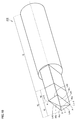
- FIG. 10 is a perspective view of the drill of the third embodiment.
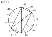
- FIG. 11 is a plan view of the drill of FIG. 10 as viewed from the apex side of the cutting edge portion.
- FIG. 12 is a cross-sectional view taken along the line XX of the drill of FIG.
- FIG. 13 is a perspective view of the drill of the fourth embodiment.
- FIG. 14 is a plan view of the drill of FIG. 13 as viewed from the apex side of the cutting edge portion.
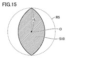
- FIG. 15 is a cross-sectional view taken along the line XX of the drill of FIG. FIG.
- FIG. 16 is a perspective view of the drill of the fifth embodiment.
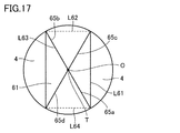
- FIG. 17 is a plan view of the drill of FIG. 16 as viewed from the apex side of the cutting edge portion.
- FIG. 18 is a cross-sectional view taken along the line XX of the drill of FIG.
- FIG. 19 is a perspective view of an example of a conventional drill using diamond for the cutting edge portion.
- FIG. 20 is a plan view of the drill of FIG. 19 as viewed from the apex side of the cutting edge portion.
- FIG. 21 is a cross-sectional view taken along the line XX of the drill of FIG.
- FIG. 22 is a diagram for explaining the drill manufactured in the embodiment.
- the drills of the present disclosure have excellent chip evacuation and long tool life.
- the drill of this disclosure is A drill having a cutting edge made of diamond and a body made of diamond continuous with the cutting edge, and rotating around a drill shaft.
- the cutting edge portion includes N cutting edges in which N is an integer of 4 or more.
- Each of the N cutting edges includes each of the N ridges connected to the apex of the N-pyramid containing the apex existing on the drill axis.
- the area of the drill in the cross section including the boundary between the cutting edge portion and the body portion is defined as S1 and the maximum value of the distance from the drill shaft to the outer edge of the drill in the cross section is defined as the normal line.
- the ratio of S1 to S2 is 30% or more and 60% or less.
- the drill of the present disclosure has excellent chip evacuation and long tool life.
- the ratio of the S1 to the S2 is preferably 45% or more and 55% or less. According to this, the chip discharge property of the drill is further improved.
- the diamond is preferably made of polycrystalline diamond having an average particle size of 100 nm or less and a purity of 99% or more. According to this, the strength, hardness and heat resistance of the drill are improved.
- the diamond is preferably made of a single crystal diamond. According to this, since the thermal conductivity is high, the wear progress of the cutting edge is slow, the edge can be easily maintained in a sharp state, and the sharpness is improved.
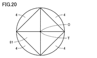
- FIG. 19 is a perspective view showing an example of a conventional drill 810 in which a diamond is used for the cutting edge portion 81.
- FIG. 20 is a plan view of the drill 810 of FIG. 19 as viewed from the tip T side of the cutting edge portion 81.
- FIG. 21 is a cross-sectional view taken along the line XX of the drill 810 of FIG.
- Diamond has high hardness, so there are restrictions on the processing shape. Therefore, as shown in FIGS. 19 and 20, in the conventional drill, the shape of the cutting edge portion 81 is an easily machined shape such as a regular square pyramid. However, according to the shape of a conventional drill, chips may accumulate in the gap between the drill and the drilled hole, which may break the drill and shorten the tool life.
- the drill of the present disclosure includes a cutting edge portion made of diamond and a body portion made of diamond continuous with the cutting edge portion, and is a drill that rotates about a drill axis, and the cutting edge portion is an integer having N of 4 or more.
- each of the N cutting edges includes each of the N ridges leading to the apex of the N-square cone, including the apex existing on the drill axis, with the drill axis as the normal line and
- S1 the maximum value of the distance from the drill shaft to the outer edge of the drill in the cross section
- r the area of the circle with r as the radius
- the ratio of S1 to S2 is 30% or more and 60% or less.
- the drill of the present disclosure has a cutting edge made of diamond, and the cutting edge includes N cutting edges in which N is an integer of 4 or more, and each of the N cutting edges exists on the drill axis. Includes each of the N ridges leading to the vertices of the N-pyramid. Such a cutting edge includes an N-pyramid surface.
- the N-pyramid surface can be formed by cutting out an object in a plane. Therefore, the cutting edge portion including the N-pyramid surface has a shape that can be easily formed by processing diamond.
- the drill axis is the normal line
- the area of the drill in the cross section including the boundary between the cutting edge portion and the body portion is S1
- the maximum distance from the drill shaft to the outer edge of the drill in the cross section is the maximum.
- the ratio of S1 to S2 is 30% or more and 60% or less.
- S1 corresponds to the area of the portion that contributes to the formation of the drilled hole in the cross section with the drill axis as the normal.
- S2 corresponds to the area of the drilled hole in the cross section with the drill axis as the normal.
- the ratio of S1 to S2 the larger the gap between the drill and the drill, and the better the chip evacuation.
- the cross-sectional area of the drill 810 shown by the diagonal line in FIG. 21 with respect to S2 (the area of the circle R8 in FIG. 21). ) Is about 64%.
- the ratio of S1 to S2 is 30% or more and 60% or less, the chip evacuation property is improved as compared with the conventional drill.
- the lower limit of the ratio of S1 to S2 is 30% from the viewpoint of ensuring the strength of the drill.
- the ratio of S1 to S2 is preferably 45% or more and 55% or less.
- the diamond forming the cutting edge portion is not particularly limited, and either natural diamond or synthetic diamond can be used.
- synthetic diamond either polycrystalline diamond or single crystal diamond can be used.
- the drill can have sufficient strength, hardness and heat resistance.
- the diamond is preferably made of polycrystalline diamond having an average particle size of 100 nm or less and a purity of 99% or more. According to this, the strength, hardness and heat resistance of the drill are further improved.
- the lower limit of the average particle size of polycrystalline diamond is not particularly limited, but can be 10 nm from the viewpoint of manufacturing.
- the average particle size of polycrystalline diamond is preferably 10 nm or more and 100 nm or less, and more preferably 10 nm or more and 30 nm or less.
- the average particle size of polycrystalline diamond in the present specification is measured by a cutting method using a scanning electron microscope. A specific measurement method will be described below.
- the surface of the polycrystalline diamond is mirror-polished, and the polished surface is observed with a scanning electron microscope (SEM) at a magnification of 30,000 to obtain an SEM image.
- SEM scanning electron microscope
- the diameter of the circle is set so that the number of diamond particles placed on one straight line is about 10 to 50.
- the number of diamond particles crossing the grain boundaries is counted for each of the above straight lines, and the average intercept length is obtained by dividing the length of the straight line by the number of crossing lines.
- the value obtained by multiplying the average section length by 1.128 is taken as the average particle size of the polycrystalline diamond in the SEM image.
- the average particle size of polycrystalline diamond is obtained for each SEM image by the above method.
- the average value of the average particle diameters of the three polycrystalline diamonds obtained is taken as the average particle diameter of the polycrystalline diamonds in the present specification.
- the purity of diamond is preferably 99% or more, more preferably 99% or more and 100% or less, and further preferably 99.99% or more and 100% or less.
- the purity of diamond can be measured by SIMS (Secondary Ion Mass Spectrometry) analysis or an X-ray diffraction pattern of polycrystalline diamond.
- the method for producing polycrystalline diamond is not particularly limited.
- polycrystalline diamond obtained by sintering a carbon substance having a graphite-type layered structure under ultra-high temperature and high pressure without adding a sintering aid or a catalyst can be used.
- Diamond is preferably made of single crystal diamond. According to this, since the thermal conductivity is high, the wear progress of the cutting edge is slow, the edge can be easily maintained in a sharp state, and the sharpness is improved.
- single crystal diamonds include natural diamonds and synthetic single crystal diamonds.
- the method for producing synthetic single crystal diamond is not particularly limited.
- synthetic single crystal diamond produced by a high pressure synthesis method or a vapor phase synthesis method can be used.
- FIG. 1 is a perspective view of the drill of the first embodiment.
- FIG. 2 is a plan view of the drill of FIG. 1 as viewed from the apex T side of the cutting edge portion.
- FIG. 3 is a cross-sectional view taken along the line XX of the drill of FIG.
- the drill 10 of the first embodiment includes a cutting edge portion 1 made of diamond, a body portion 2 connected to the cutting edge portion 1 and made of diamond, and rotates about the drill shaft O.
- the cutting edge portion refers to a portion of the drill having a cutting edge.
- the boundary between the cutting edge and the body is located on a cross section having the drill axis as a normal and passing through the end A on the body side of the longest cutting edge.
- the cutting edge portion 1 and the body portion 2 form the main body portion 3.
- the drill 10 is further connected to the main body 3 and can be provided with a connecting portion 4 for connecting the drill 10 to a holder (not shown).
- the cutting edge portion 1 includes four cutting edges 5a, 5b, 5c, and 5d.
- the cutting edges 5a and 5b have the same length, and the cutting edges 5c and 5d have the same length.
- the cutting edges 5a and 5b are longer than the cutting edges 5c and 5d.
- Each of the four cutting edges 5a, 5b, 5c, and 5d includes each of the four ridges of a regular pyramid including the apex T existing on the drill axis O.
- the regular quadrangular pyramid is shown as a regular quadrangular pyramid having the apex T of the cutting edge portion 1 as the apex and the square surrounded by the dotted lines L1, L2, L3, and L4 as the bottom surface.
- the drill shaft O is a normal line
- the area of the drill 10 in the cross section including the boundary between the cutting edge portion 1 and the body portion 2 (cross section in the XX line of FIG. 1) is S1 in the cross section.
- the ratio of S1 to S2 is 30% or more and 60% or less.
- the drill of the first embodiment has S1 (cutting of the drill 10) with respect to S2 (area of the circle R1) as compared with the conventional drill. It can be seen that the ratio of area) is small. Therefore, when the size of the machined hole is the same, the drill of the first embodiment has a larger gap between the drill and the machined hole than the conventional drill, and the chip evacuation property is improved. The drill does not break due to the accumulation of chips in the gap, and can have a long life.
- the body portion 2 has the drill shaft O as the normal line and the shape (hexagonal shape) of the drill 10 in the cross section including the boundary between the cutting edge portion and the body portion (cross section in the XX line of FIG. 1) as the bottom surface. It can have a hexagonal column shape.
- the drill when the drill includes four cutting edges at the cutting edge, and each of the four cutting edges includes each of the four ridges connected to the vertices of a regular pyramid including the vertices existing on the drill axis.
- the shape of the drill is not limited to this.
- the number N of cutting edges included in the cutting edge is an integer of 4 or more, and each of the N cutting edges is connected to the apex of a regular N pyramid including the apex existing on the drill axis. It can be in the form of including each of the ridges of.
- N is an even number of 4 or more from the viewpoint of the shape of the machined hole.
- the upper limit of N is not particularly limited, but may be, for example, 10. That is, N can be an integer of 4 or more and 10 or less, and is preferably an even number of 4 or more and 10 or less.
- the entire cutting edge portion can have a shape in which two or more vertices of the plurality of vertices of the bottom surface of the regular N-pyramid shape are cut off in a plane perpendicular to the bottom surface.
- the drill axis is the normal line, and the shape of the drill in the cross section including the boundary between the cutting edge and the body is line-symmetrical and / or point-symmetrical, and the ratio of S1 to S2 is 30%. It is preferable to cut off the apex on a plane perpendicular to the bottom surface so as to be 60% or more. As a result, in the obtained drill, the gap between the drill and the machined hole is sufficiently large, and the chip evacuation property is improved. The drill does not break due to the accumulation of chips in the gap, and can have a long life.
- FIG. 4 is a perspective view of the drill of the second embodiment.
- FIG. 5 is a plan view of the drill of FIG. 4 as viewed from the apex T side of the cutting edge portion.
- FIG. 6 is a cross-sectional view taken along the line XX of the drill of FIG.
- the drill 210 of the second embodiment can have the same configuration as the drill of the first embodiment except for the shapes of the cutting edge portion 21 and the body portion 22. Therefore, in the second embodiment, the shapes of the cutting edge portion 21 and the body portion 22 will be described.
- the cutting edge portion 21 includes eight cutting edges 25a, 25b, 25c, 25d, 25e, 25f, 25g, 25h. Of the eight cutting edges, the two cutting edges 25a and 25b have the same length and are longer than the other six cutting edges 25c, 25d, 25e, 25f, 25g and 25h.
- Each of the eight cutting edges 25a, 25b, 25c, 25d, 25e, 25f, 25g, 25h includes each of the eight ridges of an octagonal pyramid including the apex T existing on the drill axis O.
- the octagonal pyramid has an octagon having the apex T of the cutting edge portion 21 as the apex and an octagon surrounded by solid lines L21, L22, L23, L24, L25, L26, L27, and L28 as the bottom surface. Shown.
- the lengths of the cutting edges 25a, 25b, 25c, 25d, 25e, 25f, 25g, and 25h of the cutting edge and the eight ridges of the octagonal pyramid corresponding to each cutting edge are different.
- the cutting edge portion 21 has an octagonal pyramid shape.
- the bottom surface of the octagonal pyramid is a line-symmetrical and point-symmetrical octagon.
- one diagonal line D21 is the longest among the four diagonal lines D21, D22, D23, and D24 passing through the drill axis O, and the other three diagonal lines D22. , D23, D24 are shorter than the diagonal line D21.
- the drill shaft O is a normal line, and the area of the drill 210 in the cross section including the boundary between the cutting edge portion 21 and the body portion 22 (cross section in the XX line of FIG. 4) is S1.
- the ratio of S1 to S2 is 30% or more and 60% or less.
- FIG. 6 Embodiment 2
- FIG. 21 conventional drill
- the ratio of S1 to S2 is smaller in the drill of the second embodiment than in the conventional drill. Therefore, when the size of the machined hole is the same, the drill of the second embodiment has a larger gap between the drill and the machined hole than the conventional drill, and the chip evacuation property is improved. The drill does not break due to the accumulation of chips in the gap, and can have a long life.
- the body portion 22 has the drill shaft O as the normal line and the shape (octagon) of the drill 210 in the cross section including the boundary between the cutting edge portion and the body portion (cross section in the XX line of FIG. 4) as the bottom surface. It can have an octagonal pillar shape.
- the drill includes eight cutting edges at the cutting edge, and each of the eight cutting edges includes each of the eight ridges leading to the apex of the octagonal pyramid including the apex existing on the drill axis.
- the shape of the drill is not limited to this.
- the number N of cutting edges included in the cutting edge is an integer of 4 or more, and each of the N cutting edges is connected to the vertices of an N pyramid including the vertices existing on the drill axis. It can be in the form of including each of the ridges. Above all, it is preferable that N is an even number of 4 or more from the viewpoint of the shape of the machined hole.
- N When N is an even number of 4 or more, the N-sided polygon on the bottom is axisymmetric and point-symmetrical, and the (N / 2) diagonals passing through the drill axis O may include diagonals of different lengths. preferable.
- the drill 310 when N is 4 is shown in FIGS. 7 to 9.
- the upper limit of N is not particularly limited, but may be, for example, 10. That is, N can be an integer of 4 or more and 10 or less, and is preferably an even number of 4 or more and 10 or less.
- FIG. 10 is a perspective view of the drill of the third embodiment.
- FIG. 11 is a plan view of the drill of FIG. 10 as viewed from the apex T side of the cutting edge portion.
- FIG. 12 is a cross-sectional view taken along the line XX of the drill of FIG.
- the drill 410 of the third embodiment can have the same configuration as the drill of the first embodiment except for the shapes of the cutting edge portion 41 and the body portion 42. Therefore, in the third embodiment, the shapes of the cutting edge portion 41 and the body portion 42 will be described.
- the cutting edge portion 41 includes four cutting edges 45a, 45b, 45c, 45d. All four cutting edges have the same length.
- Each of the four cutting edges 45a, 45b, 45c, 45d includes each of the four ridges of a quadrangular pyramid including the apex T existing on the drill axis O.
- the quadrangular pyramid is shown as a quadrangular pyramid having the apex T of the cutting edge portion 41 as the apex and the rectangle surrounded by the solid lines L41, L42, L43, and L44 as the bottom surface.
- the lengths of the cutting edges 45a, 45b, 45c, and 45d of the cutting edge portion and each of the four ridges of the quadrangular pyramid corresponding to each cutting edge are the same. That is, the cutting edge portion 41 has a quadrangular pyramid shape. The bottom surface of the quadrangular pyramid is rectangular.
- the drill shaft O is the normal line, and the area of the drill 410 in the cross section including the boundary between the cutting edge portion and the body portion (cross section in the XX line of FIG. 10) is S1, and the drill shaft in the cross section is S1.
- the ratio of S1 to S2 is 30% or more and 60% or less.
- the drill of the third embodiment has a smaller ratio of S1 to S2 than the conventional drill. .. Therefore, when the size of the machined hole is the same, the drill of the third embodiment has a larger gap between the drill and the machined hole than the conventional drill, and the chip evacuation property is improved. The drill does not break due to the accumulation of chips in the gap, and can have a long life.
- the body portion 42 has the drill shaft O as a normal line and the shape (rectangle) of the drill 410 in the cross section including the boundary between the cutting edge portion and the body portion (cross section in the XX line of FIG. 10) as the bottom surface. It can have a prismatic shape.
- FIG. 13 is a perspective view of the drill of the fourth embodiment.
- FIG. 14 is a plan view of the drill of FIG. 13 as viewed from the apex T side of the cutting edge portion.
- FIG. 15 is a cross-sectional view taken along the line XX of the drill of FIG.
- the drill 510 of the fourth embodiment can have the same configuration as the drill of the first embodiment except for the shapes of the cutting edge portion 51 and the body portion 52. Therefore, in the fourth embodiment, the shapes of the cutting edge portion and the body portion will be described.
- the cutting edge portion 51 includes four cutting edges 55a, 55b, 55c, 55d.
- the cutting edges 55a and 55b have the same length, and the cutting edges 55c and 55d have the same length.
- the cutting edges 55a and 55b are longer than the cutting edges 55c and 55d.
- Each of the four cutting edges 55a, 55b, 55c, 55d includes each of the four ridges of a regular pyramid including the apex T existing on the drill axis O.
- the regular quadrangular pyramid is shown as a quadrangular pyramid having the apex T of the cutting edge portion 51 as the apex and the rhombus surrounded by the dotted lines L51, L52, L53, and L54 as the bottom surface.
- the drill shaft O is the normal line, and the area of the drill 510 in the cross section including the boundary between the cutting edge portion and the body portion (cross section in the XX line of FIG. 13) is S1, and the drill shaft in the cross section is S1.
- the ratio of S1 to S2 is 30% or more and 60% or less.
- the body portion 2 has the shape of the drill 510 (a plane surrounded by two arcs) in a cross section (cross section in XX line of FIG. 13) including the boundary between the cutting edge portion and the body portion, with the drill axis O as the normal line.
- Shape can be a pillar shape with the bottom surface.
- FIG. 16 is a perspective view of the drill of the fifth embodiment.
- FIG. 17 is a plan view of the drill of FIG. 16 as viewed from the apex T side of the cutting edge portion.
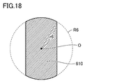
- FIG. 18 is a cross-sectional view taken along the line XX of the drill of FIG.
- the drill 610 of the fifth embodiment can have the same configuration as the drill of the first embodiment except for the shapes of the cutting edge portion 61 and the body portion 62. Therefore, in the fifth embodiment, the shapes of the cutting edge portion 61 and the body portion 62 will be described.
- the cutting edge portion 61 includes four cutting edges 65a, 65b, 65c, 65d. All four cutting edges have the same length.
- Each of the four cutting edges 65a, 65b, 65c, 65d includes each of the four ridges of a quadrangular pyramid including the apex T existing on the drill axis O.
- the quadrangular pyramid is shown as a quadrangular pyramid having the apex T of the cutting edge portion 61 as the apex and the rectangle surrounded by the solid lines L61 and L63 and the dotted lines L62 and L64 as the bottom surface.
- the drill shaft O is the normal line, and the area of the drill 610 in the cross section including the boundary between the cutting edge portion and the body portion (cross section in the XX line of FIG. 16) is S1, and the drill shaft in the cross section is S1.
- the ratio of S1 to S2 is 30% or more and 60% or less.
- the body portion 62 has the shape of the drill 610 (a set of parallel lines and a set of parallel lines) in a cross section (cross section in XX line of FIG. 16) including the boundary between the cutting edge portion and the body portion, with the drill axis O as the normal line.
- a pillar shape having a bottom surface can be used.
- the pillar shape is a shape in which the side surface of the cylinder is cut off with a set of parallel planes in the direction perpendicular to the bottom surface.
- Example 1 to Sample 8 As the drills of Samples 1 to 8, a drill (tool size: ⁇ 0.5 mm, body length 0.5 mm) having the same configuration as that of the first embodiment and having a cutting edge and a body portion made of polycrystalline diamond was prepared. ..
- FIG. 22 is a diagram showing the shape of the cross section of the drills of Samples 1 to 8 in the cross section including the boundary between the cutting edge portion and the body portion with the drill shaft O as the normal line.
- the lengths of X and Y shown in FIG. 22 in each of the drills of Samples 1 to 8 are shown in the “X ( ⁇ m)” and “Y ( ⁇ m)” columns of Table 1. Further, based on the lengths of X and Y, the ratio of the area S1 of the cross section of the drill to the area S2 of the circle R1 having r1 as the radius was calculated. The obtained values are shown in the "S1 / S2 (%)" column of Table 1.
- Example 9 As the drill of Sample 9, a drill (tool size: ⁇ 0.5 mm, body length 0.5 mm) having the same structure as that of FIG. 19 and having a cutting edge and a body portion made of polycrystalline diamond was produced.
- the cross-sectional shape of the drill of FIG. 19 is as shown in FIG. 21, and the diagonal length (the length indicated by r8 ⁇ 2 in FIG. 21) is 500 ⁇ m.
- Drilling was performed using the drills of Samples 1 to 9 under the following cutting conditions. The chip evacuation property and the number of machined holes during machining were evaluated.
- the drills of Samples 3 to 8 include four cutting edges, and the ratio of S1 to S2 (S1 / S2) is 30% or more and 60% or less, which corresponds to the example.
- the drills of Samples 3 to 8 had good chip evacuation and had a long life with 1000 or more drilled holes.
- the drills of Sample 1 and Sample 2 have a ratio of S1 to S2 (S1 / S2) of less than 30%, which corresponds to a comparative example.
- the drill of Sample 1 was unable to perform drilling because the cutting edge was damaged at the same time as the start of processing.
- the drill of Sample 2 had good chip evacuation, but had 100 drilled holes and had a shorter life than the examples.
- the drill of sample 9 has a ratio of S1 to S2 (S1 / S2) exceeding 60%, which corresponds to a comparative example.
- the drill of sample 9 had poor chip evacuation and had a short life with 10 drilled holes.
Abstract
Description
前記刃先部はNが4以上の整数であるN本の切れ刃を含み、
前記N本の切れ刃のそれぞれは、ドリル軸上に存在する頂点を含むN角錐の前記頂点につながるN本の稜のそれぞれを含み、
前記ドリル軸を法線とし、かつ、前記刃先部と前記胴体部との境界を含む断面における前記ドリルの面積をS1とし、前記断面における前記ドリル軸から前記ドリルの外縁までの距離の最大値をrとし、前記rを半径とする円の面積をS2とした場合、前記S2に対する前記S1の割合が30%以上60%以下である、ドリルである。 The drill of the present disclosure is a drill having a cutting edge portion made of diamond and a body portion made of diamond continuous with the cutting edge portion and rotating about a drill shaft.
The cutting edge portion includes N cutting edges in which N is an integer of 4 or more.
Each of the N cutting edges includes each of the N ridges leading to the apex of the N pyramid containing the apex existing on the drill axis.
The area of the drill in the cross section including the boundary between the cutting edge portion and the body portion is defined as S1 and the maximum value of the distance from the drill shaft to the outer edge of the drill in the cross section is defined as the normal line. When r is defined and the area of the circle having r as the radius is S2, the ratio of S1 to S2 is 30% or more and 60% or less.
ドリルでの穴開け加工時に、ドリルと加工穴との隙間に切屑が溜まると、ドリルが折れて工具寿命が短くなる。よって、優れた切屑排出性及び長い工具寿命を有するドリルが求められている。 [Issues to be resolved by this disclosure]
If chips accumulate in the gap between the drill and the drilled hole during drilling with a drill, the drill will break and the tool life will be shortened. Therefore, there is a demand for a drill having excellent chip evacuation and a long tool life.
本開示のドリルは、優れた切屑排出性及び長い工具寿命を有する。 [Effect of this disclosure]
The drills of the present disclosure have excellent chip evacuation and long tool life.
最初に本開示の実施態様を列記して説明する。 [Explanation of Embodiments of the present disclosure]
First, embodiments of the present disclosure will be listed and described.
ダイヤモンドからなる刃先部と、前記刃先部に連続するダイヤモンドからなる胴体部とを備え、ドリル軸を中心として回転するドリルであって、
前記刃先部はNが4以上の整数であるN本の切れ刃を含み、
前記N本の切れ刃のそれぞれは、前記ドリル軸上に存在する頂点を含むN角錐の前記頂点につながるN本の稜のそれぞれを含み、
前記ドリル軸を法線とし、かつ、前記刃先部と前記胴体部との境界を含む断面における前記ドリルの面積をS1とし、前記断面における前記ドリル軸から前記ドリルの外縁までの距離の最大値をrとし、前記rを半径とする円の面積をS2とした場合、前記S2に対する前記S1の割合が30%以上60%以下である、ドリルである。 (1) The drill of this disclosure is
A drill having a cutting edge made of diamond and a body made of diamond continuous with the cutting edge, and rotating around a drill shaft.
The cutting edge portion includes N cutting edges in which N is an integer of 4 or more.
Each of the N cutting edges includes each of the N ridges connected to the apex of the N-pyramid containing the apex existing on the drill axis.
The area of the drill in the cross section including the boundary between the cutting edge portion and the body portion is defined as S1 and the maximum value of the distance from the drill shaft to the outer edge of the drill in the cross section is defined as the normal line. When r is defined and the area of the circle having r as the radius is S2, the ratio of S1 to S2 is 30% or more and 60% or less.
本開示のドリルの具体例を、以下に図面を参照しつつ説明する。本開示の図面において、同一の参照符号は、同一部分または相当部分を表すものである。また、長さ、幅、厚さ、深さなどの寸法関係は図面の明瞭化と簡略化のために適宜変更されており、必ずしも実際の寸法関係を表すものではない。 [Details of Embodiments of the present disclosure]
Specific examples of the drills of the present disclosure will be described below with reference to the drawings. In the drawings of the present disclosure, the same reference numerals represent the same parts or equivalent parts. Further, the dimensional relationships such as length, width, thickness, and depth are appropriately changed for the purpose of clarifying and simplifying the drawings, and do not necessarily represent the actual dimensional relationships.
図1は実施の形態1のドリルの斜視図である。図2は、図1のドリルを刃先部の頂点T側から見た平面図である。図3は、図1のドリルのX-X線における断面図である。 [Embodiment 1]
FIG. 1 is a perspective view of the drill of the first embodiment. FIG. 2 is a plan view of the drill of FIG. 1 as viewed from the apex T side of the cutting edge portion. FIG. 3 is a cross-sectional view taken along the line XX of the drill of FIG.
図4は実施の形態2のドリルの斜視図である。図5は、図4のドリルを刃先部の頂点T側からから見た平面図である。図6は、図4のドリルのX-X線における断面図である。 [Embodiment 2]
FIG. 4 is a perspective view of the drill of the second embodiment. FIG. 5 is a plan view of the drill of FIG. 4 as viewed from the apex T side of the cutting edge portion. FIG. 6 is a cross-sectional view taken along the line XX of the drill of FIG.
図10は実施の形態3のドリルの斜視図である。図11は、図10のドリルを刃先部の頂点T側からから見た平面図である。図12は、図10のドリルのX-X線における断面図である。 [Embodiment 3]
FIG. 10 is a perspective view of the drill of the third embodiment. FIG. 11 is a plan view of the drill of FIG. 10 as viewed from the apex T side of the cutting edge portion. FIG. 12 is a cross-sectional view taken along the line XX of the drill of FIG.
図13は実施の形態4のドリルの斜視図である。図14は、図13のドリルを刃先部の頂点T側からから見た平面図である。図15は、図13のドリルのX-X線における断面図である。 [Embodiment 4]
FIG. 13 is a perspective view of the drill of the fourth embodiment. FIG. 14 is a plan view of the drill of FIG. 13 as viewed from the apex T side of the cutting edge portion. FIG. 15 is a cross-sectional view taken along the line XX of the drill of FIG.
図16は実施の形態5のドリルの斜視図である。図17は、図16のドリルを刃先部の頂点T側からから見た平面図である。図18は、図16のドリルのX-X線における断面図である。 [Embodiment 5]
FIG. 16 is a perspective view of the drill of the fifth embodiment. FIG. 17 is a plan view of the drill of FIG. 16 as viewed from the apex T side of the cutting edge portion. FIG. 18 is a cross-sectional view taken along the line XX of the drill of FIG.
試料1~試料8のドリルとして、実施の形態1と同様の構成を有し、刃先及び胴体部が多結晶ダイヤモンドからなるドリル(工具サイズ:φ0.5mm、胴体部長さ0.5mm)を作製した。 [
As the drills of
試料9のドリルとして、図19と同様の構成を有し、刃先及び胴体部が多結晶ダイヤモンドからなるドリル(工具サイズ:φ0.5mm、胴体部長さ0.5mm)を作製した。図19のドリルの断面形状は、図21に示される通りであり、対角線の長さ(図21においてr8×2で示される長さ)は500μmである。 [Sample 9]
As the drill of Sample 9, a drill (tool size: φ0.5 mm, body length 0.5 mm) having the same structure as that of FIG. 19 and having a cutting edge and a body portion made of polycrystalline diamond was produced. The cross-sectional shape of the drill of FIG. 19 is as shown in FIG. 21, and the diagonal length (the length indicated by r8 × 2 in FIG. 21) is 500 μm.
試料1~試料9のドリルを用いて、以下の切削条件で穴開け加工を行った。加工時の切屑排出性及び加工穴数を評価した。 [Evaluation]
Drilling was performed using the drills of
被削材材質:シリコン、厚み6.5mm
穴深さ:6mm
主軸回転数:n=30000/min
送り速度:Vf=100mm/min
Step=0.04mm
Wet加工 <Cutting conditions>
Work Material Material: Silicon, Thickness 6.5 mm
Hole depth: 6 mm
Spindle speed: n = 30,000 / min
Feed rate: Vf = 100mm / min
Step = 0.04mm
Wet processing
(切屑排出性)
A:溝に切屑が詰まらずに排出された。
B:溝に切屑の詰まりが発生した。
結果を表1の「切屑排出性」欄に示す。 <Evaluation items>
(Chip discharge property)
A: The groove was discharged without being clogged with chips.
B: The groove is clogged with chips.
The results are shown in the "Chip Emission" column of Table 1.
加工穴数10個ごとに、切れ刃の欠けの発生の有無を観察した。切れ刃に欠けが発生するまでの加工穴数を計測した。結果を表1の「加工可能穴数(個)」欄に示す。 (Number of holes that can be machined)
The presence or absence of chipping of the cutting edge was observed for every 10 machined holes. The number of machined holes until the cutting edge was chipped was counted. The results are shown in the "Number of holes that can be machined (pieces)" column in Table 1.

試料3~試料8のドリルは、4本の切れ刃を含み、S2に対するS1の割合(S1/S2)が30%以上60%以下で実施例に該当する。試料3~試料8のドリルは、切屑排出性が良好であり、加工穴数も1000個以上であり長寿命であった。 [Discussion]
The drills of
Claims (4)
- ダイヤモンドからなる刃先部と、前記刃先部に連続するダイヤモンドからなる胴体部とを備え、ドリル軸を中心として回転するドリルであって、
前記刃先部はNが4以上の整数であるN本の切れ刃を含み、
前記N本の切れ刃のそれぞれは、前記ドリル軸上に存在する頂点を含むN角錐の前記頂点につながるN本の稜のそれぞれを含み、
前記ドリル軸を法線とし、かつ、前記刃先部と前記胴体部との境界を含む断面における前記ドリルの面積をS1とし、前記断面における前記ドリル軸から前記ドリルの外縁までの距離の最大値をrとし、前記rを半径とする円の面積をS2とした場合、前記S2に対する前記S1の割合が30%以上60%以下である、ドリル。 A drill having a cutting edge made of diamond and a body made of diamond continuous with the cutting edge, and rotating around a drill shaft.
The cutting edge portion includes N cutting edges in which N is an integer of 4 or more.
Each of the N cutting edges includes each of the N ridges connected to the apex of the N-pyramid containing the apex existing on the drill axis.
The area of the drill in the cross section including the boundary between the cutting edge portion and the body portion is defined as S1 and the maximum value of the distance from the drill shaft to the outer edge of the drill in the cross section is defined as the normal. When r is defined and the area of the circle having r as the radius is S2, the ratio of the S1 to the S2 is 30% or more and 60% or less. - 前記S2に対する前記S1の割合が45%以上55%以下である、請求項1に記載のドリル。 The drill according to claim 1, wherein the ratio of the S1 to the S2 is 45% or more and 55% or less.
- 前記ダイヤモンドは、平均粒径が100nm以下、かつ、純度が99%以上の多結晶ダイヤモンドからなる、請求項1又は請求項2に記載のドリル。 The drill according to claim 1 or 2, wherein the diamond is made of polycrystalline diamond having an average particle size of 100 nm or less and a purity of 99% or more.
- 前記ダイヤモンドは、単結晶ダイヤモンドからなる、請求項1又は請求項2に記載のドリル。 The drill according to claim 1 or 2, wherein the diamond is a single crystal diamond.
Priority Applications (5)
| Application Number | Priority Date | Filing Date | Title |
|---|---|---|---|
| JP2021542009A JP7331324B2 (en) | 2019-08-27 | 2020-05-22 | Drill |
| US17/636,690 US20220288699A1 (en) | 2019-08-27 | 2020-05-22 | Drill |
| CN202080060090.7A CN114302783A (en) | 2019-08-27 | 2020-05-22 | Drill bit |
| KR1020227005931A KR20220047580A (en) | 2019-08-27 | 2020-05-22 | drill |
| EP20857066.3A EP4023375A4 (en) | 2019-08-27 | 2020-05-22 | Drill |
Applications Claiming Priority (2)
| Application Number | Priority Date | Filing Date | Title |
|---|---|---|---|
| JP2019-154555 | 2019-08-27 | ||
| JP2019154555 | 2019-08-27 |
Publications (1)
| Publication Number | Publication Date |
|---|---|
| WO2021038987A1 true WO2021038987A1 (en) | 2021-03-04 |
Family
ID=74685823
Family Applications (1)
| Application Number | Title | Priority Date | Filing Date |
|---|---|---|---|
| PCT/JP2020/020268 WO2021038987A1 (en) | 2019-08-27 | 2020-05-22 | Drill |
Country Status (6)
| Country | Link |
|---|---|
| US (1) | US20220288699A1 (en) |
| EP (1) | EP4023375A4 (en) |
| JP (1) | JP7331324B2 (en) |
| KR (1) | KR20220047580A (en) |
| CN (1) | CN114302783A (en) |
| WO (1) | WO2021038987A1 (en) |
Families Citing this family (1)
| Publication number | Priority date | Publication date | Assignee | Title |
|---|---|---|---|---|
| USD991993S1 (en) * | 2020-06-24 | 2023-07-11 | Sumitomo Electric Hardmetal Corp. | Cutting tool |
Citations (8)
| Publication number | Priority date | Publication date | Assignee | Title |
|---|---|---|---|---|
| JPH0121904B2 (en) * | 1978-09-26 | 1989-04-24 | Karuro Eruba Sutoruumentajioone Spa | |
| US4906146A (en) * | 1981-08-13 | 1990-03-06 | Bowling Roy E | Axially self-aligning drill bit |
| JPH059814U (en) * | 1991-07-15 | 1993-02-09 | 株式会社東京ダイヤモンド工具製作所 | Carbide cone |
| JP2002036017A (en) | 2000-07-25 | 2002-02-05 | Nishie Hiroshi | Drill having single crystal diamond at its tip |
| JP2003260612A (en) | 2002-03-07 | 2003-09-16 | Noritake Co Ltd | Diamond tool |
| JP2003326410A (en) * | 2002-02-27 | 2003-11-18 | Mitsubishi Materials Kobe Tools Corp | Center drill |
| JP2016120551A (en) * | 2014-12-24 | 2016-07-07 | 株式会社芝技研 | Extra fine drill |
| JP2019154555A (en) | 2018-03-08 | 2019-09-19 | 株式会社三洋物産 | Game machine |
Family Cites Families (17)
| Publication number | Priority date | Publication date | Assignee | Title |
|---|---|---|---|---|
| JPS496766Y1 (en) * | 1970-09-11 | 1974-02-18 | ||
| JPS5566717U (en) * | 1978-10-30 | 1980-05-08 | ||
| JP3066996U (en) * | 1999-08-30 | 2000-03-07 | 株式会社東京ダイヤモンド工具製作所 | Drilling tool |
| US7097396B1 (en) * | 2000-02-16 | 2006-08-29 | Kabushiki Kaisha Miyanaga | Drill bit |
| JP2002001722A (en) * | 2000-06-21 | 2002-01-08 | Toshiba Ceramics Co Ltd | Method for drilling member made of silicon and drill used therefor |
| JP2002160112A (en) * | 2000-11-28 | 2002-06-04 | Nishie Hiroshi | Drill having polycrystal diamond at its tip |
| JP2002166317A (en) * | 2000-12-01 | 2002-06-11 | Canon Inc | Rotary cutting tool, method for cutting work, and fine shaped object |
| JP2005297124A (en) * | 2004-04-12 | 2005-10-27 | Nachi Fujikoshi Corp | Drill |
| JP2006255814A (en) * | 2005-03-16 | 2006-09-28 | Micro Diamond Corp | Micro rotating tool |
| KR101032667B1 (en) * | 2010-08-16 | 2011-05-06 | 고대권 | Center drill |
| JP5914446B2 (en) * | 2012-10-30 | 2016-05-11 | 株式会社アライドマテリアル | Cutting tool and workpiece machining method using the same |
| EP3035871B1 (en) * | 2013-08-21 | 2019-05-29 | Michael J. Scianamblo | Bone drill |
| CN204818197U (en) * | 2015-07-13 | 2015-12-02 | 廊坊西波尔钻石技术有限公司 | A diamond bit for little spot facing work |
| JP2018161717A (en) * | 2017-03-27 | 2018-10-18 | 三菱マテリアル株式会社 | drill |
| JP6968346B2 (en) * | 2017-08-01 | 2021-11-17 | 福井県 | Diamond grains for tools and their manufacturing methods |
| JP6311059B1 (en) * | 2017-09-20 | 2018-04-11 | 株式会社芝技研 | Thin drill |
| CN110933944B (en) * | 2018-07-20 | 2022-10-18 | 住友电气工业株式会社 | Diamond polycrystal and tool comprising same |
-
2020
- 2020-05-22 KR KR1020227005931A patent/KR20220047580A/en active Search and Examination
- 2020-05-22 EP EP20857066.3A patent/EP4023375A4/en active Pending
- 2020-05-22 CN CN202080060090.7A patent/CN114302783A/en active Pending
- 2020-05-22 US US17/636,690 patent/US20220288699A1/en active Pending
- 2020-05-22 WO PCT/JP2020/020268 patent/WO2021038987A1/en unknown
- 2020-05-22 JP JP2021542009A patent/JP7331324B2/en active Active
Patent Citations (8)
| Publication number | Priority date | Publication date | Assignee | Title |
|---|---|---|---|---|
| JPH0121904B2 (en) * | 1978-09-26 | 1989-04-24 | Karuro Eruba Sutoruumentajioone Spa | |
| US4906146A (en) * | 1981-08-13 | 1990-03-06 | Bowling Roy E | Axially self-aligning drill bit |
| JPH059814U (en) * | 1991-07-15 | 1993-02-09 | 株式会社東京ダイヤモンド工具製作所 | Carbide cone |
| JP2002036017A (en) | 2000-07-25 | 2002-02-05 | Nishie Hiroshi | Drill having single crystal diamond at its tip |
| JP2003326410A (en) * | 2002-02-27 | 2003-11-18 | Mitsubishi Materials Kobe Tools Corp | Center drill |
| JP2003260612A (en) | 2002-03-07 | 2003-09-16 | Noritake Co Ltd | Diamond tool |
| JP2016120551A (en) * | 2014-12-24 | 2016-07-07 | 株式会社芝技研 | Extra fine drill |
| JP2019154555A (en) | 2018-03-08 | 2019-09-19 | 株式会社三洋物産 | Game machine |
Also Published As
| Publication number | Publication date |
|---|---|
| CN114302783A (en) | 2022-04-08 |
| EP4023375A1 (en) | 2022-07-06 |
| JP7331324B2 (en) | 2023-08-23 |
| JPWO2021038987A1 (en) | 2021-03-04 |
| US20220288699A1 (en) | 2022-09-15 |
| KR20220047580A (en) | 2022-04-18 |
| EP4023375A4 (en) | 2022-10-26 |
Similar Documents
| Publication | Publication Date | Title |
|---|---|---|
| JP6603955B2 (en) | Throwaway tip | |
| JP6618025B2 (en) | Cutting tool and manufacturing method thereof | |
| US20080152438A1 (en) | Ballnose end mill | |
| WO2016017780A1 (en) | Cutting insert and replaceable cutting edge cutting tool | |
| JPWO2015008724A1 (en) | Cutting insert, cutting tool, and method of manufacturing cut workpiece | |
| JP2007021677A (en) | Electrodeposition wire tool | |
| JPWO2008093748A1 (en) | Drill insert and drill, and work material cutting method | |
| SE504312C2 (en) | Method of working composites | |
| WO2017187693A1 (en) | Cutting tool | |
| WO2021038987A1 (en) | Drill | |
| WO2018123133A1 (en) | Cutting tool and method for manufacturing same | |
| WO2021066046A1 (en) | Rotary cutting tool | |
| AT15012U1 (en) | drilling | |
| JP2015193049A (en) | Cutting insert, and tip replaceable rotary cutting tool | |
| JP2006255814A (en) | Micro rotating tool | |
| JP5612382B2 (en) | Cutting insert | |
| AT15965U1 (en) | milling | |
| JP6697131B1 (en) | Reamer | |
| JP3639227B2 (en) | Drilling tools for brittle materials | |
| WO2021261380A1 (en) | Cutting tool | |
| JP2020157393A (en) | Cutting tool | |
| JP6080304B2 (en) | Cutting tools | |
| WO2021181518A1 (en) | Reamer | |
| JP2010264531A (en) | Cutting-edge replaceable drill | |
| JPH0819911A (en) | Drill |
Legal Events
| Date | Code | Title | Description |
|---|---|---|---|
| 121 | Ep: the epo has been informed by wipo that ep was designated in this application |
Ref document number: 20857066 Country of ref document: EP Kind code of ref document: A1 |
|
| ENP | Entry into the national phase |
Ref document number: 2021542009 Country of ref document: JP Kind code of ref document: A |
|
| ENP | Entry into the national phase |
Ref document number: 20227005931 Country of ref document: KR Kind code of ref document: A |
|
| NENP | Non-entry into the national phase |
Ref country code: DE |
|
| ENP | Entry into the national phase |
Ref document number: 2020857066 Country of ref document: EP Effective date: 20220328 |