WO2021033390A1 - 判定システム、判定方法、プログラム - Google Patents
判定システム、判定方法、プログラム Download PDFInfo
- Publication number
- WO2021033390A1 WO2021033390A1 PCT/JP2020/021948 JP2020021948W WO2021033390A1 WO 2021033390 A1 WO2021033390 A1 WO 2021033390A1 JP 2020021948 W JP2020021948 W JP 2020021948W WO 2021033390 A1 WO2021033390 A1 WO 2021033390A1
- Authority
- WO
- WIPO (PCT)
- Prior art keywords
- stirring
- unit
- state
- determination system
- determination
- Prior art date
- Legal status (The legal status is an assumption and is not a legal conclusion. Google has not performed a legal analysis and makes no representation as to the accuracy of the status listed.)
- Ceased
Links
Images


Classifications
-
- G—PHYSICS
- G01—MEASURING; TESTING
- G01N—INVESTIGATING OR ANALYSING MATERIALS BY DETERMINING THEIR CHEMICAL OR PHYSICAL PROPERTIES
- G01N11/00—Investigating flow properties of materials, e.g. viscosity, plasticity; Analysing materials by determining flow properties
- G01N11/10—Investigating flow properties of materials, e.g. viscosity, plasticity; Analysing materials by determining flow properties by moving a body within the material
- G01N11/14—Investigating flow properties of materials, e.g. viscosity, plasticity; Analysing materials by determining flow properties by moving a body within the material by using rotary bodies, e.g. vane
-
- B—PERFORMING OPERATIONS; TRANSPORTING
- B01—PHYSICAL OR CHEMICAL PROCESSES OR APPARATUS IN GENERAL
- B01F—MIXING, e.g. DISSOLVING, EMULSIFYING OR DISPERSING
- B01F27/00—Mixers with rotary stirring devices in fixed receptacles; Kneaders
-
- B—PERFORMING OPERATIONS; TRANSPORTING
- B01—PHYSICAL OR CHEMICAL PROCESSES OR APPARATUS IN GENERAL
- B01F—MIXING, e.g. DISSOLVING, EMULSIFYING OR DISPERSING
- B01F35/00—Accessories for mixers; Auxiliary operations or auxiliary devices; Parts or details of general application
Definitions
- the present disclosure relates to a determination system, a determination method, and a program for determining the state of the agitated object to be agitated by the agitator.
- Patent Document 1 discloses a viscosity change detecting element for detecting a viscosity change of a liquid.
- the viscosity change detection element includes an elastic body capable of flexural elastic deformation and / or torsional elastic deformation, and a movable permanent magnet attached directly to the elastic body or via a connecting member so as to move according to the deformation of the elastic body. And have.
- a part of the elastic body is fixed to a support for supporting the viscosity change detection element, so that the elastic body is flexed and elastically deformed with rotation and / or vibration in a rotating liquid. And / or twist elastic deformation occurs.
- the relative position of the movable permanent magnet with respect to the external detection means provided at the fixed position changes according to the change in the viscosity of the liquid, and the change in the viscosity of the liquid is detected by detecting the relative position change by the external detection means. Can be detected.
- the acquisition unit of the determination system acquires waveform data showing a waveform related to the current supplied to the drive device that drives the stirrer that agitates the object to be agitated.
- the determination unit acquires the force applied to the drive device obtained from the waveform data.
- the state of the agitated object is determined based on the change caused by the component in the specific direction of.
- This judgment system can improve the accuracy of judgment of the state of the agitated object.
- FIG. 1 is a block diagram of the determination system of the embodiment.
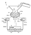
- FIG. 2 is a perspective view of the stirrer of the determination system of the embodiment.
- FIG. 3 is a diagram showing a waveform related to the current supplied to the driving device of the stirrer.
- FIG. 4 is a diagram showing a waveform related to the current supplied to the driving device of the stirrer.
- FIG. 5 is a diagram showing a frequency component of a current supplied to the driving device of the stirrer.
- FIG. 6 is a diagram showing a frequency component of a current supplied to the driving device of the stirrer.
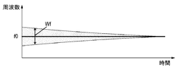
- FIG. 7 is a diagram showing a frequency range of the current supplied to the driving device of the stirrer.
- FIG. 8 is a flowchart of the operation of the determination system.
- FIG. 9 is a diagram showing an example of control using the determination system.
- FIG. 10 is a diagram showing another control using the determination system.
- FIG. 1 is a block diagram of the determination system 10 of the embodiment.
- FIG. 2 is a perspective view of the stirrer 30 using the determination system 10.
- the determination system 10 includes an acquisition unit 11 and a determination unit 13.
- the acquisition unit 11 acquires waveform data showing a waveform related to the current I30 supplied to the driving device 31 of the agitator 30 that agitates the agitated object 40.
- the determination unit 13 determines the state of the stirring object 40 from the change caused by the component of the force applied to the driving device 31 in the specific direction obtained from the waveform data.
- the determination system 10 and the stirrer 30 constitute a stirring system 1001.
- the determination system 10 in determining the state of the agitated object 40, waveform data showing a waveform related to the current I30 supplied to the drive device 31 of the agitator 30 is used. That is, in determining the state of the stirring object 40, the determination system 10 obtains waveform data showing a waveform related to the current I30 supplied to the drive device 31.
- the state of the stirring object 40 is determined in the surrounding environment of the agitator 30. Be less affected. Therefore, according to the determination system 10, the accuracy of determining the state of the stirring object 40 can be improved.
- Patent Document 1 In the viscosity change detection element disclosed in Patent Document 1, it is necessary for the viscosity change detection element to actually come into contact with a liquid (object to be agitated), and damage / deterioration in a high temperature, an oil atmosphere, or the like becomes a problem. Further, Patent Document 1 utilizes a change caused by a flexural elastic deformation and / or a torsional elastic deformation of an elastic body accompanied by rotation and / or vibration, and such a change is affected by ambient vibration and noise. Easy to receive. Therefore, the viscosity change detection element disclosed in Patent Document 1 has insufficient accuracy in determining the state of the agitated object.
- the accuracy of determining the state of the stirring object 40 can be improved.
- the determination system 10 determines the state of the agitated object 40 to be agitated by the agitator 30.
- the stirrer 30 stirs the agitated object 40.
- stirring may include concepts such as dispersion, kneading, mixing and the like. Therefore, the stirrer 30 is not a stirrer in a strict sense, but may be a disperser, a kneader, a mixer, or the like.
- the object to be agitated 40 is made of one or more kinds of materials. That is, the agitated object 40 may be made of a single material or may be made of two or more materials (for example, different materials). Examples of the 40 objects to be agitated include fluids, powders and the like. More specifically, the stirring object 40 may be a resin material such as an aqueous solution, a mixed gas, or rubber.
- the stirring object 40 may be a dispersion in which a solid substance is dispersed in a liquid such as water, and may be, for example, a mixture of cement and water (concrete, mortar, asphalt, etc.).
- the stirring object 40 may be a food product, and examples thereof include butter, margarine, mayonnaise, cream, minced meat, rice cake, and dough (dough for bread, confectionery, noodles, etc.).
- the stirrer 30 shown in FIG. 2 stirs the agitated object 40 to obtain the agitated object 40 having a predetermined state.
- the stirrer 30 includes a drive device 31, an electric wire 32, a control device 33, and a mechanism unit 34.
- the mechanical unit 34 stirs the agitated object 40.
- the mechanism unit 34 has a stirring space 340 inside for stirring the stirring object 40.
- the mechanism unit 34 includes a plurality of rotating bodies 341 and 342 for stirring the stirring object 40 in the stirring space 340.
- the rotating bodies 341 and 342 are, for example, stirring blades.
- the two rotating bodies 341 and 342 can rotate independently of each other.
- the stirring object 40 is agitated by the rotation of the rotating bodies 341 and 342.
- the drive device 31 drives the mechanism unit 34.
- the drive device 31 is the power source for the mechanism unit 34.
- the drive device 31 includes a plurality of motors 311, 312.
- the output of the motors 311, 312 changes according to the given current.
- the motors 311, 312 rotate the rotating bodies 341 and 342 of the stirrer 30 independently of each other.
- the rotating shaft 311ax on which the rotor 311a of the motor 311 rotates is parallel to the shaft 341ax on which the rotating body 341 rotates.
- the rotating shaft 312ax on which the rotor 312a of the motor 312 rotates is parallel to the rotating shaft 342ax of the rotating body 342.
- Motors 311, 312 are AC motors that operate with AC.
- the AC motor may be a three-phase AC motor or a single-phase AC motor.
- the motors 311, 312 change their output, that is, the rotation speed (rotational speed per unit time) according to the change in the reference frequency of the given alternating current.
- the reference frequency is not high, the output will be large (the output shaft will rotate fast and the rotation speed will be high), and if the reference frequency is low, the output will be small (the output shaft will rotate slowly and the rotation speed will be low). Become).
- the control device 33 controls the drive device 31.
- the control device 33 is connected to the drive device 31 via the electric wire 32, and supplies the current I30 to the drive device 31 via the electric wire 32.
- the control device 33 includes power supply devices 331 and 332.
- the electric wire 32 includes electric wires 321 and 322.
- the power supply devices 331 and 332 are connected to the motors 31 and 312 of the drive device 31 via electric wires 321 and 322, respectively, and the currents I31 and I32 are supplied to the motors 31 and 312 of the drive device 31 by the electric wires 321 and 322, respectively.
- the currents I31 and I32 when the currents I31 and I32 are not distinguished, they may be simply referred to as the current I30.
- the power supply devices 331 and 332 supply the currents I31 and I32 to the motors 31 and 312 of the drive device 31 in order to stir the stirring object 40 by the mechanism unit 34, respectively. That is, the currents I31 and I32 are supplied to the drive device 31 in a state where the stirrer 30 is stirring the stirring object 40.
- the motors 311, 312 are AC motors
- the currents I31 and I32 are ACs having a reference frequency.
- the power supply devices 331 and 332 adjust the reference frequencies of the currents I31 and I32.
- the judgment system 10 determines the viscosity of the stirring target 40 as the state of the stirring target 40. That is, the determination system 10 has a function as a viscosity measurement system. As shown in FIG. 1, the determination system 10 includes a measurement unit 20. Further, the determination system 10 includes an acquisition unit 11, an extraction unit 12, a determination unit 13, an output unit 14, a collection unit 15, a generation unit 16, and a storage unit 17.
- the measuring unit 20 measures the current I30 supplied to the driving device 31 of the stirrer 30 and outputs waveform data (current waveform data) showing a waveform related to the current I30.
- the measuring unit 20 is attached to an electric wire 32 through which the current I30 from the control device 33 to the driving device 31 flows.
- the measuring unit 20 includes a current sensor.
- the measuring unit 20 includes a differential type current sensor. Therefore, the waveform data is data showing a differential waveform of the current I30. Examples of this type of differential current sensor include a current transformer and a search coil. By using this kind of differential type current sensor, the measuring unit 20 can be retrofitted to the electric wire 32.
- the measuring unit 20 In the determination system 10, it is not necessary to install the measuring unit 20 in the vicinity of the rotors 311a and 312a of the drive device 31, especially the motors 311, 312. Since the measuring unit 20 only needs to be able to measure the current I30 supplied to the driving device 31, it can be installed inside a control panel or the like that houses the control device 33. Therefore, in the mechanism unit 34, there is no need for a device for installing the measurement unit 20 and wiring, and there is no need for balance adjustment of the mechanism unit 34 due to the installation of the measurement unit 20. Further, for this reason, when installing the measuring unit 20, it is not necessary to take measures (for example, oil resistance measures, heat resistance measures, waterproof measures, etc.) so that the measuring unit 20 can be used while stirring the stirring object 40.
- measures for example, oil resistance measures, heat resistance measures, waterproof measures, etc.
- the maintenance burden of the measuring unit 20 can be reduced.
- the waveform data can be acquired even when the stirrer 30 is working, that is, the stirring target 40 is being stirred. Therefore, it is not necessary to interrupt the work of the stirrer 30 for the judgment by the judgment system 10, and therefore, the lengthening of the stirring work due to the judgment can be reduced. Further, since the waveform data can be acquired even during the work of the agitator 30, the state of the agitated object 40 can be grasped at any time.
- FIGS. 3 and 4 show time-axis waveforms of the current I30 supplied to the drive device 31 of the stirrer 30.
- the time axis waveform shows the value of the current with respect to time.
- FIG. 3 shows the waveform of the current I30 immediately after the start of stirring the stirring object 40.
- FIG. 4 shows the waveform of the current I30 after a sufficient time has elapsed from the start of stirring the stirring object 40.
- FIGS. 3 and 4 are virtual waveforms rather than actual waveforms.
- FIG. 5 and 6 show frequency axis waveforms showing the frequency components of the current I30 supplied to the drive device 31 of the stirrer 30.
- the frequency axis waveform shows the value of the current component with respect to the frequency.
- FIG. 5 shows the frequency component of the current I30 of FIG. 3, that is, the frequency component of the current I30 immediately after the start of stirring the stirring object 40.
- the peak W1 at the reference frequency f0 and the peaks W2 and W3 of the sideband wave at the reference frequency f0 can be seen.
- FIG. 6 shows the frequency component of the current I30 of FIG. 4, that is, the frequency component of the current I30 after a sufficient time has elapsed from the start of stirring the stirring object 40.
- the peak W1 of the reference frequency f0 is seen, and the peaks W2 and W3 corresponding to the sideband waves with respect to the reference frequency f0 are not seen.
- FIG. 7 shows the time change of the distribution range of the frequency component of the current I30.
- the range Wf of the frequency component of the current I30 is distributed around the reference frequency f0, and converges to the reference frequency f0 with the passage of time.
- the viscosity of the stirring target 40 decreases as time elapses from the start of stirring.
- the stirring target 40 becomes hard enough to be uniformly mixed, the viscosity of the stirring target 40 increases as time elapses from the start of stirring.
- the change in the distribution range Wf of the frequency component of the current I30 is caused by the component of the force applied to the drive device 31, that is, the force applied to the rotors 311a and 312a of the motors 311, 312 in a specific direction.
- the rotating bodies 341 and 342 are difficult to rotate smoothly, and irregular forces are applied to the rotating bodies 341 and 342 in the rotation direction of the rotating bodies 341 and 342.
- the state of the agitated object 40 agitated by the agitator 30 is determined by utilizing the correlation between the state of the agitated object 40 and the change caused by the component of the force applied to the drive device 31 in a specific direction. judge.
- the specific direction described above depends on the configuration of the stirrer 30.
- the specific direction may change depending on the direction in which the stirrer 30 exerts a force on the stirring object 40 with respect to the rotating shafts 311ax and 312ax of the rotors 311a and 312a of the motors 311, 312. .
- the specific direction described above is a direction intersecting the rotation axis of the rotor 311a of the motor 311.
- the acquisition unit 11 acquires waveform data (current waveform data) showing a waveform related to the current I30 supplied to the drive device 31 of the stirrer 30. More specifically, the acquisition unit 11 is connected to the measurement unit 20 and acquires waveform data from the measurement unit 20. The waveform data from the measuring unit 20 is data showing a waveform obtained by differentiating the current I30 with respect to time. The acquisition unit 11 acquires waveform data (current waveform data) showing waveforms related to the currents I31 and I32 supplied to the motors 31 and 312 of the drive device 31 of the stirrer 30.
- the extraction unit 12 acquires the information used by the determination unit 13 from the waveform data acquired by the acquisition unit 11.
- the information used by the determination unit 13 is information regarding a change caused by a component of the force applied to the drive device 31 in a specific direction.
- the extraction unit 12 converts the time-axis waveform (see FIGS. 3 and 4) indicated by the waveform data acquired by the acquisition unit 11 into a frequency-axis waveform (see FIGS. 5 and 6).
- the time axis waveform can be converted into a frequency axis waveform by, for example, a fast Fourier transform (FFT).
- FFT fast Fourier transform
- the extraction unit 12 extracts from the frequency axis waveform obtained by the conversion a portion of interest that may include a change due to a component of the force applied to the driving device 31 in a specific direction.
- the distribution range Wf of the frequency component of the current I30 spreads around the reference frequency f0 and converges to the reference frequency f0 with the passage of time.
- the frequency component of the current I30 includes the reference frequency f0 and the sideband wave, and the change in the state of the stirring object 40 may affect the change in the sideband wave more than the reference frequency f0. Therefore, the extraction unit 12 may extract a portion corresponding to the sideband wave as a portion of interest from the frequency axis waveform.
- the determination unit 13 determines the state of the agitated object 40 to be agitated by the agitator 30 from the change caused by the component of the force applied to the drive device 31 in the specific direction. In the present embodiment, the determination unit 13 determines the state of the stirring object 40 based on the portion of interest extracted by the extraction unit 12. In the present embodiment, the determination unit 13 determines the viscosity of the stirring target 40 as the state of the stirring target 40.
- the determination unit 13 determines the state of the stirring object 40 by using the learned model M11.
- the trained model M11 is designed to output a value (state value) indicating the state of the stirring object 40 for a given input (part of interest).
- the determination unit 13 gives the portion of interest obtained from the extraction unit 12 to the trained model M11, and determines the state of the stirring object 40 based on the state value obtained from the trained model M11.
- the state value may correspond to the viscosity, and in this case, the determination unit 13 can obtain the viscosity (current viscosity) of the stirrer 30 from the state value obtained from the trained model M11.
- Such a trained model M11 can be generated by supervised learning using learning data (data set) that defines the relationship between the label corresponding to the state value and the portion of interest.
- the trained model M11 is stored in the storage unit 17.
- the storage unit 17 may store the learned model M11 for each type of motors 311, 312. That is, the determination unit 13 may use different trained models M11 for each of the motors 311, 312.
- the determination unit 13 can determine the state of the stirring object 40.
- the determination unit 13 can determine whether or not the stirring target object 40 has a predetermined softness.
- the work of adjusting the softness of the stirring object 40 to a predetermined softness can be easily performed.
- the determination unit 13 can determine whether or not the stirring target 40 has a predetermined hardness. As a result, the work of adjusting the hardness of the agitated object 40 to a predetermined hardness can be easily performed.
- the acquisition unit 11 obtains waveform data of two types of currents I31 and I32. Therefore, the state of the agitated object 40 can be obtained from each of the waveform data of the two types of currents I31 and I32.
- the determination unit 13 may determine the final state of the stirring object 40 from the state of the stirring target 40 corresponding to the waveform data of the two types of currents I31 and I32, respectively. For example, a representative value of the viscosity of the stirring object 40 corresponding to the currents I31 and I32 may be used as the final viscosity of the stirring object 40.
- the representative value can be appropriately selected from an average value, a maximum value, a minimum value, a mode value, and the like.
- the output unit 14 outputs the result of the determination by the determination unit 13.
- the output unit 14 includes, for example, an audio output device and a display.
- the display is, for example, a thin display device such as a liquid crystal display or an organic EL display.
- the output unit 14 may display the result of the determination by the determination unit 13 on the display or notify the result by the voice output device. Further, the output unit 14 may transmit or store the result of the determination by the determination unit 13 as data to the external device.
- the output unit 14 does not need to have both an audio output device and a display. Further, the output unit 14 can also output the result of the determination by the determination unit 13 by e-mail or the like.
- the collection unit 15 collects and accumulates the data acquired by the acquisition unit 11.
- the data acquired by the acquisition unit 11 includes the waveform data from the measurement unit 20.
- the data collected by the collecting unit 15 is used for generating and improving the trained model M11.
- the generation unit 16 generates the trained model M11 used by the determination unit 13.
- the generation unit 16 generates a trained model M11 by a machine learning algorithm using a certain amount or more of training data.
- the learning data may be prepared in advance, or may be generated from the data accumulated by the collecting unit 15. By adopting the learning data generated from the data accumulated by the collecting unit 15, it is expected that the accuracy of the state determination using the trained model M11 will be further improved.
- the generation unit 16 evaluates the newly generated trained model M11, and when the evaluation of the trained model M11 improves, the trained model M11 stored in the storage unit 17 is replaced with the newly generated trained model M11.
- the trained model M11 is updated.
- supervised learning can be appropriately used as described above.
- supervised learning a typical multi-layer neural network having a supervised learning mechanism can be used.
- the acquisition unit 11, the extraction unit 12, the determination unit 13, the output unit 14, the collection unit 15, and the generation unit 16 are, for example, one or more processors (for example, a microprocessor). It can be realized by a computer system including one or more memories. That is, when one or more processors execute one or more programs stored in one or more memories, the acquisition unit 11, the extraction unit 12, the determination unit 13, the output unit 14, the collection unit 15, and so on. It functions as a generator 16.
- the one or more programs may be recorded in advance in a memory, may be recorded through a telecommunication line such as the Internet, or may be recorded and provided on a non-temporary recording medium such as a memory card.
- the acquisition unit 11 acquires waveform data (current waveform data) showing waveforms related to the currents I31 and I32 supplied to the motors 31 and 312 of the drive device 31 of the stirrer 30 (step S11).
- the extraction unit 12 converts the waveform indicated by the waveform data acquired by the acquisition unit 11 into a frequency axis waveform, and the force applied to the rotors 311a and 312a of the drive device 31, particularly the motors 311 and 312, from the frequency axis waveform.
- a portion containing a change due to a component in a specific direction of is extracted (step S12).
- the determination unit 13 determines the state of the stirring object 40 from the portion of interest extracted by the extraction unit 12 using the plurality of trained models M11 (step S13).
- the output unit 14 outputs the result of the determination by the determination unit 13 (S14). In this way, the determination system 10 can determine the state of the agitated object 40 to be agitated by the agitator 30 from the waveform data showing the waveforms related to the currents I31 and I32 supplied to the drive device 31, and present the result. ..
- FIG. 9 shows an example of control of the stirrer 30 using the determination system 10.
- the determination system 10 determines the viscosity as the state of the agitated object 40.
- FIG. 9 determines the control conditions of the stirrer 30 in which the viscosity of the stirring object 40 becomes the target value V11 based on the history (time change) of the state (viscosity) of the stirring object 40 determined by the determination system 10.
- a predicted value of the state (viscosity) of the stirring object 40 after the time t12 is obtained from the history (time change) of the state (viscosity) of the stirring object 40 obtained by the time t12. Note that FIG.
- the control conditions of the stirrer 30 are determined in consideration of the difference between the predicted value of the viscosity of the agitated object 40 and the measured value of the viscosity of the agitated object 40.
- the control conditions of the stirrer 30 may include the temperature of the agitated object 40 and the stirring period. For example, by changing the temperature of the stirring object 40, it is possible to obtain the stirring target 40 having a viscosity of the target value V11 without changing the stirring period (stirring end time t11).
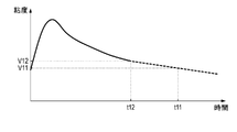
- FIG. 10 shows another example of control of the stirrer 30 using the determination system 10.
- the determination system 10 determines the viscosity as the state of the agitated object 40.
- FIG. 10 shows an example of adjusting the stirring period in the stirrer 30 based on the state of the stirring target 40 determined by the determination system 10.
- the determination system 10 determines the viscosity of the agitated object 40. Stirring with the stirrer 30 is continued until the difference between the viscosity value of the stirring object 40 determined by the determination system 10 and the target value V21 becomes zero. That is, the stirring by the stirrer 30 is continued until the viscosity of the stirring object 40 reaches the target value V21.
- the viscosity of the stirring object 40 is determined using the determination system 10, and if the viscosity value V22 of the stirring object 40 at this time is different from the target value V21, stirring by the stirrer 30 is continued. To do. Then, at time t22, since the value of the viscosity of the stirring object 40 determined by the determination system 10 matches the target value V21, the stirring by the stirrer 30 is terminated. As a result, at the end of stirring, it is possible to obtain the stirring object 40 having a viscosity of the target value V21.
- the state of the stirring object 40 can be easily adjusted to a desired state. Therefore, it is not necessary to rely on the feeling of a skilled worker or the like, and it is possible to suppress variations in the state of the agitated object 40.
- the determination system 10 described above includes an acquisition unit 11 and a determination unit 13.
- the acquisition unit 11 acquires waveform data showing a waveform related to the current I30 supplied to the driving device 31 of the agitator 30 that agitates the agitated object 40.
- the determination unit 13 determines the state of the stirring object 40 from the change caused by the component of the force applied to the driving device 31 in the specific direction obtained from the waveform data. According to such a determination system 10, the accuracy of determining the state of the stirring object 40 can be improved.
- the determination system 10 executes the following determination method.
- the determination method includes an acquisition step and a determination step.
- the acquisition step is a step of acquiring waveform data showing a waveform related to the current I30 supplied to the drive device 31 of the stirrer 30 that stirs the stirring object 40.
- the determination step is a step of determining the state of the stirring object 40 from the change caused by the component of the force applied to the driving device 31 in the specific direction obtained from the waveform data. According to such a determination method, the accuracy of determining the state of the stirring object 40 can be improved.
- the judgment system 10 is realized by a computer system including one or more processors. That is, the determination system 10 is realized by executing a program (determination program) by one or more processors.
- This program is a program (computer program) for causing one or more processors to execute the determination method. According to such a program, the accuracy of determining the state of the agitated object 40 can be improved as in the determination method.
- the acquisition unit 11 does not necessarily have to acquire waveform data of two types of currents I31 and I32.
- the acquisition unit 11 may acquire only the waveform data of the current I30 supplied to one of the motors 311, 312, that is, one of the currents I31 and I32.
- the measuring unit 20 needs to measure only one of the currents I31 and I32.
- the acquisition unit 11 may acquire waveform data of a plurality of currents having more than two.
- the acquisition unit 11 may acquire waveform data when the rotation speeds of the rotating bodies 341 and 342 are changed.
- the influence of the state of the stirring object 40 may be reflected in the current I30 supplied to the drive device 31.
- the waveform data of the current I30 acquired by the acquisition unit 11 will change due to the state of the stirring object 40. Therefore, the accuracy of determining the state of the stirring object 40 can be further improved.
- the acquisition unit 11 may acquire waveform data when a predetermined process is performed on the stirring object 40.
- the predetermined treatment is a treatment that positively causes the stirring target 40 to be changed by an external factor. Examples of the predetermined treatment include heating, cooling, pressurizing, depressurizing, and the like of the stirring object 40.
- the state of the agitated object 40 is not limited to the viscosity, but may be a numerical value representing the state of the agitated object 40 such as the Reynolds number, the ratio of solid matter (dumb), and the degree of agitation. Further, the state of the stirring object 40 is not limited to a numerical value, and may be an event such as a normal state, an abnormal state, or an unspecified state. That is, the state of the stirring object 40 may be a quantitative state or a qualitative state.
- the determination system 10 does not necessarily have to include the measurement unit 20.
- the determination system 10 includes the acquisition unit 11, the extraction unit 12, the determination unit 13, the output unit 14, the collection unit 15, the generation unit 16, and the storage unit. It may only have 17.
- the measuring unit 20 does not necessarily have to include a differential type current sensor, and may be another conventionally known current sensor.
- the determination system 10 does not necessarily have to have the collection unit 15, the generation unit 16, and the storage unit 17. That is, the determination system 10 does not have to have a function of updating the trained model M11 by itself. Further, the storage unit 17 does not necessarily have to store a plurality of trained models M11.
- the extraction unit 12 is not essential.
- the determination system 10 does not have to extract the portion including the change caused by the component of the force applied to the driving device 31 in the specific direction.
- the state of the stirrer 30 may be obtained as an output from the trained model M11 by inputting the entire waveform indicated by the waveform data acquired by the acquisition unit 11. That is, the extraction of the portion including the change may be omitted.
- the determination system 10 does not necessarily have to have the output unit 14.
- the determination system 10 may be able to output the state of the stirring object 40 determined by the determination unit 13 to the outside of the determination system 10.
- the determination system 10 may be composed of a plurality of computers, and the functions of the determination system 10 (particularly, the acquisition unit 11, the extraction unit 12, the determination unit 13, the output unit 14, the collection unit 15, and the generation unit 16). ) May be distributed to a plurality of devices.
- the acquisition unit 11, the extraction unit 12, the determination unit 13, and the output unit 14 may be provided in a personal computer or the like installed in a facility having equipment, and the generation unit 16 and the output unit 14 may be provided in an external server or the like. It may be provided.
- the determination system 10 is realized by the cooperation of the personal computer and the server. Further, at least a part of the functions of the determination system 10 may be realized by, for example, the cloud (cloud computing).
- the execution subject of the determination system 10 described above includes a computer system.
- a computer system has a processor and memory as hardware.
- the processor executes the program recorded in the memory of the computer system, the function as the execution subject of the determination system 10 in the present disclosure is realized.
- the program may be pre-recorded in the memory of the computer system or may be provided through a telecommunication line.
- the program may also be provided recorded on a non-temporary recording medium such as a memory card, optical disk, or hard disk drive that can be read by a computer system.
- a processor in a computer system is composed of one or more electronic circuits including a semiconductor integrated circuit (IC) or a large scale integrated circuit (LSI).
- IC semiconductor integrated circuit
- LSI large scale integrated circuit
- ICs and LSIs may be called system LSIs, VLSIs (very large scale integrations), or ULSIs (very large scale integrations), depending on the degree of integration.
- a field programmable gate array (FPPA) that is programmed after the LSI is manufactured, or a reconfigurable logical device that can reconfigure the junction relationships inside the LSI or set up circuit partitions inside the LSI should also be used for the same purpose. Can be done.
- a plurality of electronic circuits may be integrated on one chip, or may be distributed on a plurality of chips. The plurality of chips may be integrated in one device, or may be distributed in a plurality of devices.
- the first aspect is a determination system (10), which includes an acquisition unit (11) and a determination unit (13).
- the acquisition unit (11) acquires waveform data showing waveforms related to currents (I30, I31, I32) supplied to the drive device (31) of the stirrer (30) that agitates the agitated object (40).
- the determination unit (13) determines the state of the stirring object (40) from the change caused by the component of the force applied to the driving device (31) in the specific direction obtained from the waveform data. According to this aspect, the accuracy of determining the state of the stirring object (40) can be improved.
- the second aspect is the determination system (10) based on the first aspect.
- the currents (I30, I31, I32) are supplied to the driving device (31) during stirring of the stirring object (40).
- the state of the agitated object (40) can be determined without interrupting the agitation in the agitator (30).
- the third aspect is the determination system (10) based on the first or second aspect.
- the driving device (31) includes a motor (311, 312) for rotating a rotating body (341, 342) for stirring the stirring object (40).
- the force applied to the drive device (31) is the force applied to the rotors (311a, 312a) of the motor (311, 312). According to this aspect, the accuracy of determining the state of the stirring object (40) can be further improved.
- the fourth aspect is the determination system (10) based on the third aspect.
- the driving device (31) includes a plurality of the motors (311 and 312) that independently rotate the plurality of rotating bodies (341 and 342). According to this aspect, the accuracy of determining the state of the stirring object (40) can be further improved.
- the fifth aspect is the determination system (10) based on the third or fourth aspect.
- the acquisition unit (11) acquires the waveform data when the rotation speed of the rotating body (341, 342) is changed. According to this aspect, the accuracy of determining the state of the stirring object (40) can be further improved.
- the sixth aspect is a determination system (10) based on any one of the first to fourth aspects.
- the acquisition unit (11) acquires the waveform data when the stirring object (40) is subjected to a predetermined process. According to this aspect, the accuracy of determining the state of the stirring object (40) can be further improved.
- the seventh aspect is a determination system (10) based on any one of the first to sixth aspects.
- the determination unit (13) determines the viscosity of the stirring object (40). According to this aspect, it is possible to determine the viscosity of the agitated object (40).
- the eighth aspect is the determination system (10) based on any one of the first to sixth aspects.
- the stirring object (40) becomes softer as it is uniformly mixed.
- the determination unit (13) determines whether the stirring object (40) has a predetermined softness. According to this aspect, the work of adjusting the softness of the stirring object (40) to a predetermined softness can be easily performed.
- the ninth aspect is a determination system (10) based on any one of the first to sixth aspects.
- the stirring object (40) becomes harder as it is uniformly mixed.
- the determination unit (13) determines whether the stirring object (40) has a predetermined hardness. According to this aspect, the work of adjusting the hardness of the agitated object (40) to a predetermined hardness can be easily performed.
- the tenth aspect is a determination system (10) based on any one of the first to ninth aspects.
- the determination system (10) further includes an extraction unit (12) that converts the waveform into a frequency axis waveform and extracts a portion that may include the change from the frequency axis waveform.
- the determination unit (13) determines the state of the stirring object (40) based on the portion extracted by the extraction unit (12). According to this aspect, the accuracy of determining the state of the stirring object (40) can be further improved.
- the eleventh aspect is a determination system (10) based on the tenth aspect.
- the determination unit (13) determines the state of the stirring object (40) from the portion using the trained model (M11). According to this aspect, the accuracy of determining the state of the stirring object (40) can be further improved.
- the twelfth aspect is a determination system (10) based on any one of the first to eleventh aspects.
- the determination system (10) further includes a measurement unit (20) that measures the currents (I30, I31, I32) and outputs the waveform data.
- the measuring unit (20) includes a differential type current sensor. According to this aspect, the accuracy of determining the state of the stirring object (40) can be improved.
- the thirteenth aspect is a determination system (10) based on the twelfth aspect.
- the measuring unit (20) is attached to an electric wire (32,321,322) through which the current (I30, I31, I32) flows. According to this aspect, the determination system (10) can be easily implemented.
- the 14th aspect is a determination method, which includes an acquisition step and a determination step.
- the acquisition step is a step of acquiring waveform data showing waveforms related to currents (I30, I31, I32) supplied to the drive device (31) of the stirrer (30) that stirs the stirring object (40).
- the determination step is a step of determining the target state of the stirring object (40) from the change caused by the component of the force applied to the driving device (31) in the specific direction obtained from the waveform data. According to this aspect, the accuracy of determining the state of the stirring object (40) can be improved.
- the fifteenth aspect is a program, which is a program for causing one or more processors to execute the determination method of the fourteenth aspect. According to this aspect, the accuracy of determining the state of the stirring object (40) can be improved.
- Judgment system 11 Acquisition unit 12 Extraction unit 13 Judgment unit 20 Measurement unit 30 Stirrer 31 Drive device 311, 312 Motors 311a, 312a Rotor 32, 321, 322 Electric wire 341,342 Rotating body 40 Stirring object I30, I31, I32 Current M11 trained model
Landscapes
- Chemical & Material Sciences (AREA)
- General Health & Medical Sciences (AREA)
- Life Sciences & Earth Sciences (AREA)
- Health & Medical Sciences (AREA)
- Analytical Chemistry (AREA)
- Biochemistry (AREA)
- Physics & Mathematics (AREA)
- General Physics & Mathematics (AREA)
- Immunology (AREA)
- Pathology (AREA)
- Chemical Kinetics & Catalysis (AREA)
- Mixers Of The Rotary Stirring Type (AREA)
- Accessories For Mixers (AREA)
Priority Applications (2)
| Application Number | Priority Date | Filing Date | Title |
|---|---|---|---|
| JP2021540639A JP7539114B2 (ja) | 2019-08-22 | 2020-06-03 | 判定システム、判定方法、プログラム |
| CN202080036047.7A CN113825561B (zh) | 2019-08-22 | 2020-06-03 | 判定系统、判定方法、程序产品 |
Applications Claiming Priority (2)
| Application Number | Priority Date | Filing Date | Title |
|---|---|---|---|
| JP2019-152367 | 2019-08-22 | ||
| JP2019152367 | 2019-08-22 |
Publications (1)
| Publication Number | Publication Date |
|---|---|
| WO2021033390A1 true WO2021033390A1 (ja) | 2021-02-25 |
Family
ID=74660846
Family Applications (1)
| Application Number | Title | Priority Date | Filing Date |
|---|---|---|---|
| PCT/JP2020/021948 Ceased WO2021033390A1 (ja) | 2019-08-22 | 2020-06-03 | 判定システム、判定方法、プログラム |
Country Status (3)
| Country | Link |
|---|---|
| JP (1) | JP7539114B2 (https=) |
| CN (1) | CN113825561B (https=) |
| WO (1) | WO2021033390A1 (https=) |
Cited By (6)
| Publication number | Priority date | Publication date | Assignee | Title |
|---|---|---|---|---|
| JP7154664B1 (ja) | 2022-03-30 | 2022-10-18 | 鈴鹿エンヂニヤリング株式会社 | 混練調整方法 |
| JP7299655B1 (ja) | 2022-03-30 | 2023-06-28 | 鈴鹿エンヂニヤリング株式会社 | 混練状態の評価方法および混練機 |
| WO2023190764A1 (ja) | 2022-03-30 | 2023-10-05 | 鈴鹿エンヂニヤリング株式会社 | 混練状態の評価方法、混練機、および混練調整方法 |
| JP7542290B1 (ja) | 2024-03-26 | 2024-08-30 | 株式会社写真化学 | 撹拌・脱泡処理データ分析装置、処理条件決定装置及び撹拌・脱泡処理システム |
| WO2024257887A1 (ja) | 2023-06-16 | 2024-12-19 | 鈴鹿エンヂニヤリング株式会社 | 混練状態の評価方法および混練機 |
| WO2025028197A1 (ja) * | 2023-07-31 | 2025-02-06 | 長瀬産業株式会社 | サーバ、方法、およびプログラム |
Citations (5)
| Publication number | Priority date | Publication date | Assignee | Title |
|---|---|---|---|---|
| JPH01163533U (https=) * | 1988-05-06 | 1989-11-15 | ||
| JPH11295205A (ja) * | 1998-04-09 | 1999-10-29 | Kanegafuchi Chem Ind Co Ltd | 攪拌装置及び攪拌方法 |
| JP2015073942A (ja) * | 2013-10-09 | 2015-04-20 | 株式会社日立製作所 | 水処理システム |
| JP2015102713A (ja) * | 2013-11-26 | 2015-06-04 | キヤノン株式会社 | 画像形成装置 |
| JP2016109674A (ja) * | 2014-12-02 | 2016-06-20 | 株式会社品川工業所 | 被処理物の状態変化を検出する装置、プログラム、および方法、ならびに処理装置 |
Family Cites Families (6)
| Publication number | Priority date | Publication date | Assignee | Title |
|---|---|---|---|---|
| JP2004101444A (ja) * | 2002-09-11 | 2004-04-02 | Fuji Photo Film Co Ltd | 濃度検出方法及び装置 |
| JP4782664B2 (ja) * | 2006-12-06 | 2011-09-28 | テーブルマーク株式会社 | 食品生地の混練状態の挙動検知方法 |
| WO2012122594A1 (en) * | 2011-03-14 | 2012-09-20 | Breville Pty Limited | Ice cream maker |
| JP5168609B2 (ja) * | 2011-06-30 | 2013-03-21 | Dic株式会社 | 反応液の粘度を検知する方法、反応液の粘度検知装置、反応生成物を得る方法及び反応生成物を得るための製造装置 |
| JP2015132570A (ja) * | 2014-01-15 | 2015-07-23 | 富士工業株式会社 | 粘度測定装置及び粘度測定方法 |
| WO2016042481A1 (en) * | 2014-09-15 | 2016-03-24 | Stellenbosch University | A method and system for determining fluid density |
-
2020
- 2020-06-03 CN CN202080036047.7A patent/CN113825561B/zh active Active
- 2020-06-03 JP JP2021540639A patent/JP7539114B2/ja active Active
- 2020-06-03 WO PCT/JP2020/021948 patent/WO2021033390A1/ja not_active Ceased
Patent Citations (5)
| Publication number | Priority date | Publication date | Assignee | Title |
|---|---|---|---|---|
| JPH01163533U (https=) * | 1988-05-06 | 1989-11-15 | ||
| JPH11295205A (ja) * | 1998-04-09 | 1999-10-29 | Kanegafuchi Chem Ind Co Ltd | 攪拌装置及び攪拌方法 |
| JP2015073942A (ja) * | 2013-10-09 | 2015-04-20 | 株式会社日立製作所 | 水処理システム |
| JP2015102713A (ja) * | 2013-11-26 | 2015-06-04 | キヤノン株式会社 | 画像形成装置 |
| JP2016109674A (ja) * | 2014-12-02 | 2016-06-20 | 株式会社品川工業所 | 被処理物の状態変化を検出する装置、プログラム、および方法、ならびに処理装置 |
Cited By (10)
| Publication number | Priority date | Publication date | Assignee | Title |
|---|---|---|---|---|
| JP7154664B1 (ja) | 2022-03-30 | 2022-10-18 | 鈴鹿エンヂニヤリング株式会社 | 混練調整方法 |
| JP7299655B1 (ja) | 2022-03-30 | 2023-06-28 | 鈴鹿エンヂニヤリング株式会社 | 混練状態の評価方法および混練機 |
| WO2023190764A1 (ja) | 2022-03-30 | 2023-10-05 | 鈴鹿エンヂニヤリング株式会社 | 混練状態の評価方法、混練機、および混練調整方法 |
| JP2023149270A (ja) * | 2022-03-30 | 2023-10-13 | 鈴鹿エンヂニヤリング株式会社 | 混練調整方法 |
| JP2023152636A (ja) * | 2022-03-30 | 2023-10-17 | 鈴鹿エンヂニヤリング株式会社 | 混練状態の評価方法および混練機 |
| WO2024257887A1 (ja) | 2023-06-16 | 2024-12-19 | 鈴鹿エンヂニヤリング株式会社 | 混練状態の評価方法および混練機 |
| KR20250173523A (ko) | 2023-06-16 | 2025-12-10 | 수주카 엔지니어링 가부시키가이샤 | 혼련 상태의 평가 방법 및 혼련기 |
| WO2025028197A1 (ja) * | 2023-07-31 | 2025-02-06 | 長瀬産業株式会社 | サーバ、方法、およびプログラム |
| JP7542290B1 (ja) | 2024-03-26 | 2024-08-30 | 株式会社写真化学 | 撹拌・脱泡処理データ分析装置、処理条件決定装置及び撹拌・脱泡処理システム |
| JP2025149042A (ja) * | 2024-03-26 | 2025-10-08 | 株式会社写真化学 | 撹拌・脱泡処理データ分析装置、処理条件決定装置及び撹拌・脱泡処理システム |
Also Published As
| Publication number | Publication date |
|---|---|
| JP7539114B2 (ja) | 2024-08-23 |
| JPWO2021033390A1 (https=) | 2021-02-25 |
| CN113825561A (zh) | 2021-12-21 |
| CN113825561B (zh) | 2024-11-12 |
Similar Documents
| Publication | Publication Date | Title |
|---|---|---|
| JP7539114B2 (ja) | 判定システム、判定方法、プログラム | |
| Aydogmus et al. | A web-based remote access laboratory using SCADA | |
| US6774601B2 (en) | System and method for predicting mechanical failures in machinery driven by an induction motor | |
| CN104755947B (zh) | 用于基于阻抗分析的机电系统的诊断的方法 | |
| US20150094964A1 (en) | Viscoelasticity measurement method and viscoelasticity measurement device | |
| CN114070135A (zh) | 伺服马达装置、控制方法 | |
| JP2018195266A (ja) | 状態分析装置、状態分析方法、およびプログラム | |
| CN1918522B (zh) | 煤炭研磨机器 | |
| Kumar et al. | Development of LDA based indicator for the detection of unbalance and misalignment at different shaft speeds | |
| AU2002248976B2 (en) | Fluid properties evaluation | |
| AU2002248976A1 (en) | Fluid properties evaluation | |
| JP6771353B2 (ja) | 電気モータを動作させる方法 | |
| WO2021029366A1 (ja) | 軸継手の特性評価装置及び特性評価方法 | |
| CN102022314A (zh) | 风扇的测试治具及测试系统 | |
| KR102595992B1 (ko) | 점성 추정 장치 및 점성 추정 방법 | |
| JP6727152B2 (ja) | 撹拌中のクリームのホイップ状態の検知方法及びホイップドクリーム製造方法 | |
| CN106095019B (zh) | 信息处理装置及pos终端装置 | |
| JP2014001995A (ja) | 撹拌機能付き粘度測定方法およびその装置 | |
| TW202112486A (zh) | 軸聯結器之特性評價裝置及特性評價方法 | |
| Hashimoto et al. | Development of a torque-sensorless viscometer for food processing applications | |
| Hefft et al. | Monitoring Rheological Changes Using Acoustic Emissions for Complex Formulated Fluids Manufacturing | |
| WO2004070359A1 (en) | Yield test method and apparatus | |
| Horiuchi et al. | IND-01 M-MATE (MEASURING-MACHINE FOR THE ANGULAR TRANSMISSION ERROR)(INDUSTRIAL SESSION) | |
| Kirana | The Design of Tachometer Contact and Non-Contact Using Microcontroller | |
| TW202244650A (zh) | 診斷系統、診斷方法及程式 |
Legal Events
| Date | Code | Title | Description |
|---|---|---|---|
| 121 | Ep: the epo has been informed by wipo that ep was designated in this application |
Ref document number: 20855677 Country of ref document: EP Kind code of ref document: A1 |
|
| ENP | Entry into the national phase |
Ref document number: 2021540639 Country of ref document: JP Kind code of ref document: A |
|
| NENP | Non-entry into the national phase |
Ref country code: DE |
|
| 122 | Ep: pct application non-entry in european phase |
Ref document number: 20855677 Country of ref document: EP Kind code of ref document: A1 |