WO2021025127A1 - Molding unit for cooling resin molded article, blow molding device, injection molding device, and method - Google Patents
Molding unit for cooling resin molded article, blow molding device, injection molding device, and method Download PDFInfo
- Publication number
- WO2021025127A1 WO2021025127A1 PCT/JP2020/030227 JP2020030227W WO2021025127A1 WO 2021025127 A1 WO2021025127 A1 WO 2021025127A1 JP 2020030227 W JP2020030227 W JP 2020030227W WO 2021025127 A1 WO2021025127 A1 WO 2021025127A1
- Authority
- WO
- WIPO (PCT)
- Prior art keywords
- preform
- mold
- temperature
- cooling
- injection molding
- Prior art date
Links
Images


Classifications
-
- B—PERFORMING OPERATIONS; TRANSPORTING
- B29—WORKING OF PLASTICS; WORKING OF SUBSTANCES IN A PLASTIC STATE IN GENERAL
- B29C—SHAPING OR JOINING OF PLASTICS; SHAPING OF MATERIAL IN A PLASTIC STATE, NOT OTHERWISE PROVIDED FOR; AFTER-TREATMENT OF THE SHAPED PRODUCTS, e.g. REPAIRING
- B29C49/00—Blow-moulding, i.e. blowing a preform or parison to a desired shape within a mould; Apparatus therefor
- B29C49/02—Combined blow-moulding and manufacture of the preform or the parison
- B29C49/06—Injection blow-moulding
-
- B—PERFORMING OPERATIONS; TRANSPORTING
- B29—WORKING OF PLASTICS; WORKING OF SUBSTANCES IN A PLASTIC STATE IN GENERAL
- B29C—SHAPING OR JOINING OF PLASTICS; SHAPING OF MATERIAL IN A PLASTIC STATE, NOT OTHERWISE PROVIDED FOR; AFTER-TREATMENT OF THE SHAPED PRODUCTS, e.g. REPAIRING
- B29C49/00—Blow-moulding, i.e. blowing a preform or parison to a desired shape within a mould; Apparatus therefor
- B29C49/42—Component parts, details or accessories; Auxiliary operations
- B29C49/64—Heating or cooling preforms, parisons or blown articles
- B29C49/6409—Thermal conditioning of preforms
- B29C49/6427—Cooling of preforms
- B29C49/643—Cooling of preforms from the inside
-
- B—PERFORMING OPERATIONS; TRANSPORTING
- B29—WORKING OF PLASTICS; WORKING OF SUBSTANCES IN A PLASTIC STATE IN GENERAL
- B29C—SHAPING OR JOINING OF PLASTICS; SHAPING OF MATERIAL IN A PLASTIC STATE, NOT OTHERWISE PROVIDED FOR; AFTER-TREATMENT OF THE SHAPED PRODUCTS, e.g. REPAIRING
- B29C49/00—Blow-moulding, i.e. blowing a preform or parison to a desired shape within a mould; Apparatus therefor
- B29C49/02—Combined blow-moulding and manufacture of the preform or the parison
- B29C49/06—Injection blow-moulding
- B29C49/061—Injection blow-moulding with parison holding means displaceable between injection and blow stations
- B29C49/062—Injection blow-moulding with parison holding means displaceable between injection and blow stations following an arcuate path, e.g. rotary or oscillating-type
-
- B—PERFORMING OPERATIONS; TRANSPORTING
- B29—WORKING OF PLASTICS; WORKING OF SUBSTANCES IN A PLASTIC STATE IN GENERAL
- B29C—SHAPING OR JOINING OF PLASTICS; SHAPING OF MATERIAL IN A PLASTIC STATE, NOT OTHERWISE PROVIDED FOR; AFTER-TREATMENT OF THE SHAPED PRODUCTS, e.g. REPAIRING
- B29C49/00—Blow-moulding, i.e. blowing a preform or parison to a desired shape within a mould; Apparatus therefor
- B29C49/42—Component parts, details or accessories; Auxiliary operations
- B29C49/48—Moulds
-
- B—PERFORMING OPERATIONS; TRANSPORTING
- B29—WORKING OF PLASTICS; WORKING OF SUBSTANCES IN A PLASTIC STATE IN GENERAL
- B29C—SHAPING OR JOINING OF PLASTICS; SHAPING OF MATERIAL IN A PLASTIC STATE, NOT OTHERWISE PROVIDED FOR; AFTER-TREATMENT OF THE SHAPED PRODUCTS, e.g. REPAIRING
- B29C49/00—Blow-moulding, i.e. blowing a preform or parison to a desired shape within a mould; Apparatus therefor
- B29C49/42—Component parts, details or accessories; Auxiliary operations
- B29C49/56—Opening, closing or clamping means
-
- B—PERFORMING OPERATIONS; TRANSPORTING
- B29—WORKING OF PLASTICS; WORKING OF SUBSTANCES IN A PLASTIC STATE IN GENERAL
- B29C—SHAPING OR JOINING OF PLASTICS; SHAPING OF MATERIAL IN A PLASTIC STATE, NOT OTHERWISE PROVIDED FOR; AFTER-TREATMENT OF THE SHAPED PRODUCTS, e.g. REPAIRING
- B29C49/00—Blow-moulding, i.e. blowing a preform or parison to a desired shape within a mould; Apparatus therefor
- B29C49/42—Component parts, details or accessories; Auxiliary operations
- B29C49/64—Heating or cooling preforms, parisons or blown articles
- B29C49/6409—Thermal conditioning of preforms
- B29C49/6463—Thermal conditioning of preforms by contact heating or cooling, e.g. mandrels or cores specially adapted for heating or cooling preforms
- B29C49/6467—Thermal conditioning of preforms by contact heating or cooling, e.g. mandrels or cores specially adapted for heating or cooling preforms on the outside
-
- B—PERFORMING OPERATIONS; TRANSPORTING
- B29—WORKING OF PLASTICS; WORKING OF SUBSTANCES IN A PLASTIC STATE IN GENERAL
- B29C—SHAPING OR JOINING OF PLASTICS; SHAPING OF MATERIAL IN A PLASTIC STATE, NOT OTHERWISE PROVIDED FOR; AFTER-TREATMENT OF THE SHAPED PRODUCTS, e.g. REPAIRING
- B29C49/00—Blow-moulding, i.e. blowing a preform or parison to a desired shape within a mould; Apparatus therefor
- B29C49/42—Component parts, details or accessories; Auxiliary operations
- B29C49/70—Removing or ejecting blown articles from the mould
-
- B—PERFORMING OPERATIONS; TRANSPORTING
- B29—WORKING OF PLASTICS; WORKING OF SUBSTANCES IN A PLASTIC STATE IN GENERAL
- B29C—SHAPING OR JOINING OF PLASTICS; SHAPING OF MATERIAL IN A PLASTIC STATE, NOT OTHERWISE PROVIDED FOR; AFTER-TREATMENT OF THE SHAPED PRODUCTS, e.g. REPAIRING
- B29C49/00—Blow-moulding, i.e. blowing a preform or parison to a desired shape within a mould; Apparatus therefor
- B29C49/42—Component parts, details or accessories; Auxiliary operations
- B29C49/78—Measuring, controlling or regulating
- B29C49/786—Temperature
-
- B—PERFORMING OPERATIONS; TRANSPORTING
- B29—WORKING OF PLASTICS; WORKING OF SUBSTANCES IN A PLASTIC STATE IN GENERAL
- B29C—SHAPING OR JOINING OF PLASTICS; SHAPING OF MATERIAL IN A PLASTIC STATE, NOT OTHERWISE PROVIDED FOR; AFTER-TREATMENT OF THE SHAPED PRODUCTS, e.g. REPAIRING
- B29C49/00—Blow-moulding, i.e. blowing a preform or parison to a desired shape within a mould; Apparatus therefor
- B29C49/02—Combined blow-moulding and manufacture of the preform or the parison
- B29C2049/023—Combined blow-moulding and manufacture of the preform or the parison using inherent heat of the preform, i.e. 1 step blow moulding
-
- B—PERFORMING OPERATIONS; TRANSPORTING
- B29—WORKING OF PLASTICS; WORKING OF SUBSTANCES IN A PLASTIC STATE IN GENERAL
- B29C—SHAPING OR JOINING OF PLASTICS; SHAPING OF MATERIAL IN A PLASTIC STATE, NOT OTHERWISE PROVIDED FOR; AFTER-TREATMENT OF THE SHAPED PRODUCTS, e.g. REPAIRING
- B29C2949/00—Indexing scheme relating to blow-moulding
- B29C2949/07—Preforms or parisons characterised by their configuration
- B29C2949/0715—Preforms or parisons characterised by their configuration the preform having one end closed
Definitions
- the present invention relates to a mold unit for cooling a resin molded product, a blow molding device, an injection molding device, and a method.
- a hot parison type blow molding device has been known as one of the manufacturing devices for resin containers.
- the hot parison type blow molding device has a configuration in which a resin container is blow molded by utilizing the heat retained during injection molding of the preform, and is a resin container that is more diverse and has an excellent aesthetic appearance as compared with the cold parison type. It is advantageous in that it can be manufactured.
- an object of the present invention is to provide a cooling mold unit capable of improving the efficiency of additional cooling and temperature adjustment of a preform in a high temperature state.
- One aspect of the present invention is a cooling mold unit for cooling an injection-molded bottomed resin preform, which has an outer shape corresponding to the internal shape of the preform and is a preform.
- a core mold that can be inserted inside is provided, and an exhaust port that exhausts air from the inside of the preform through the inside of the core mold is provided at the tip of the core mold that faces the bottom of the preform.
- Another aspect of the present invention is a cooling mold unit for cooling an injection-molded bottomed resin preform, which has an outer shape corresponding to the internal shape of the preform and has a preform.
- a core mold that can be inserted into the inside of the core mold is provided, and an exhaust groove extending from the tip end side to the base end side of the preform insertion portion is provided on the surface of the core mold that faces the inner surface of the preform.
- FIG. 1 It is a figure which shows typically the structure of the blow molding apparatus of 1st Embodiment. It is a figure which shows the structural example of the temperature adjustment part. It is a perspective view which shows the structural example of a cooling pipe.
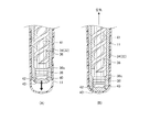
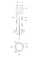
- A) is a bottom view of the core mold
- B) is a cross-sectional view of the core pin of the core mold
- C) is a cross-sectional view of the main body of the core mold.
- It is a flowchart which shows the process of the blow molding method. It is a graph which shows the temperature change example of the preform in the blow molding method of this embodiment and a comparative example.
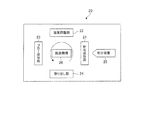
- FIG. 1 is a diagram schematically showing the configuration of the blow molding apparatus 20 of the first embodiment.
- the blow molding apparatus 20 of the present embodiment is of a hot parison method (also referred to as a one-stage method) in which a container is blow-molded by utilizing the retained heat (internal heat amount) at the time of injection molding without cooling the preform 11 to room temperature. It is a device.
- the transport mechanism 26 includes a rotating plate (not shown) that rotates about an axis in the direction perpendicular to the paper surface of FIG. 1.
- a rotating plate On the rotating plate, one or more neck molds 27 (not shown in FIG. 1) holding the neck portion 12 of the preform 11 or the resin container (hereinafter, simply referred to as a container) are arranged at each predetermined angle.
- the transport mechanism 26 transfers the preform 11 (or container) in which the neck portion 12 is held by the neck mold 27 to the injection molding portion 21, the temperature adjusting portion 22, the blow molding portion 23, and the take-out portion 24.
- Transport in the order of.
- the transport mechanism 26 can also raise and lower the rotating plate, and also performs operations related to mold closing and mold opening (release) of the preform in the injection molding unit 21.
- the injection molding unit 21 includes an injection cavity type and an injection core type, which are not shown, respectively, and manufactures the preform 11 shown in FIG.
- An injection device 25 that supplies a resin material that is a raw material of the preform 11 is connected to the injection molding unit 21.
- the injection cavity mold and the injection core mold and the neck mold 27 of the transport mechanism 26 are closed to form a preform-shaped mold space. Then, by pouring the resin material from the injection device 25 into such a preform-shaped mold space, the injection molding unit 21 manufactures the preform 11.
- the overall shape of the preform 11 is a bottomed cylindrical shape in which one end side is open and the other end side is closed.
- a neck portion 12 is formed at the end portion of the preform 11 on the opening side.
- the material of the container and the preform 11 is a thermoplastic synthetic resin, and can be appropriately selected according to the use of the container.
- Specific types of materials include, for example, PET (polyethylene terephthalate), PEN (polyethylene naphthalate), PCTA (polycyclohexanedimethylene terephthalate), Tritan (Tritan (registered trademark): copolyester manufactured by Eastman Chemical Co., Ltd.).
- PP polypropylene
- PE polyethylene
- PC polyethylene
- PES polyether sulfone
- PPSU polyphenyl sulfone
- PS polystyrene
- COP / COC cyclic olefin polymer
- PMMA polymethacrylic acid
- Methyl: acrylic acrylic
- PLA polylactic acid
- the neck mold 27 of the transport mechanism 26 is not opened and the preform 11 is held and conveyed as it is.
- the number of preforms 11 simultaneously molded by the injection molding unit 21 (that is, the number of containers that can be simultaneously molded by the blow molding apparatus 20) can be appropriately set.
- the cavity mold 31 is a mold having a space for temperature adjustment having substantially the same shape as the outer shape of the preform 11 manufactured by the injection molding unit 21, and is arranged on the support base 33.
- the cavity type 31 of the present embodiment has an upper stage type 31a and a lower stage type 31b, and is divided into upper and lower stages.
- the temperature of the cavity type 31 is maintained at a predetermined temperature by the temperature adjusting medium flowing inside the upper type 31a and the lower type 31b.
- the temperature distribution of the preform 11 may be changed in the longitudinal direction of the preform 11.
- the temperature of the temperature adjusting medium of the cavity type 31 is not particularly limited, but can be appropriately selected within the range of, for example, 5 ° C. to 80 ° C., preferably 30 ° C. to 60 ° C. ..
- the configuration of the cavity type 31 is not limited to the configuration of the present embodiment.
- the cavity type 31 may be configured to be divided into three upper and lower stages.
- the cavity mold 31 may be composed of a pair of split molds divided in the longitudinal direction of the preform 11.
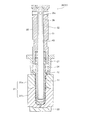
- the core mold 32 is a mold inserted inside the preform 11, and is arranged so as to be able to advance and retreat with respect to the neck mold 27 holding the preform 11 in the temperature adjusting unit 22.
- FIG. 2 shows a state in which the core mold 32 extends downward in the figure and is inserted into the neck mold 27.
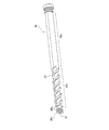
- the core mold 32 includes at least a core pin (first core mold) 34, a main body portion (second core mold) 35, and a cooling pipe 36.
- the core pin 34 is a bottomed tubular rod-shaped member inserted into the preform 11, and has an outer shape substantially the same as the internal shape of the preform 11. Further, inside the core pin 34, a cylindrical internal space for flowing the temperature adjusting medium is formed along the axial direction.
- the exhaust port 40 is formed in a shape that is rotationally symmetric in the circumferential direction of the core mold 32 (more specifically, the core pin 34) with reference to the central axis of the core mold 32 (more specifically, the core pin 34). ing. If the exhaust port 40 is formed so as to be rotationally symmetric in the circumferential direction of the core mold 32 (more specifically, the core pin 34), the air in the preform 11 can be easily discharged evenly and evenly in the circumferential direction. The uneven contact between the core mold 32 and the preform 11 is less likely to occur. For example, in FIG. 4A, four exhaust ports 40 are formed at the tips of core pins 34 at intervals of 90 degrees so as to form point symmetry in the circumferential direction.
- the exhaust ports 40 do not necessarily have to be arranged rotationally symmetrically, and for example, at the tip of the core mold 32 (more specifically, the core pin 34), any arbitrary exhaust port 40 within a predetermined distance range from the central axis thereof.
- a plurality of exhaust ports 40 may be arranged at the positions.
- the number of exhaust ports 40 provided on the core pin 34 is a number other than 4 (an integer of 2 or 3 or more). May be good. Further, one exhaust port 40 may be provided at the position of the central axis of the core pin 34 (center of the core pin).
- the cooling pipe 36 is a tubular member inserted into the internal space of the core mold 32.
- the outer circumference of the cooling pipe 36 divides the internal space of the core mold 32 into two along the axial direction to form a flow path 43 of the temperature adjusting medium.
- a first region 36a corresponding to the main body 35 and a second region 36b corresponding to the core pin 34 are formed on the outer periphery of the cooling pipe 36 in the axial direction, respectively.
- the first region 36a of the cooling pipe 36 has an oval cross section in which a circle having an outer diameter corresponding to the internal space is cut out on both the left and right sides.
- a spiral partition wall 37 forming a double-threaded screw is formed on the outer periphery of the pipe.
- the outer diameter of the partition wall 37 is set to a dimension corresponding to the inner diameter of the internal space.
- a circular sealing portion 36c in which the O-ring 38 is fitted is provided on the outer periphery of the tip of the cooling pipe 36.
- the sealing portion 36c has a function of axially partitioning the exhaust chamber 42 formed on the tip end side of the core pin 34 and the flow path 43 of the temperature adjusting medium formed on the outer periphery of the cooling pipe 36.
- a region 36d in which the partition wall 37 is not formed is provided in the vicinity of the sealing portion 36c.
- an exhaust passage 41 extending in the axial direction from one end to the other end of the cooling pipe is formed.
- the exhaust passage 41 has a function of discharging the air that has flowed into the core pin 34 from the exhaust port 40 of the core pin 34 to the outside of the core mold 32.
- the exhaust chamber connected to the exhaust port 40 and the exhaust passage 41 is between the bottom surface side of the internal space of the core pin 34 and the tip of the cooling pipe 36. 42 is formed.
- the flow path 43 of the temperature control medium has a first flow path 43a connected to the introduction path 35a of the temperature control medium and a second flow path 43b connected to the discharge path 35b of the temperature control medium.
- the first flow path 43a is formed on the right side in FIG. 2 with respect to the cooling pipe 36
- the second flow path 43b is formed on the left side in FIG. 2 with respect to the cooling pipe 36. It is formed.
- the first flow path 43a and the second flow path 43b are alternately arranged along the axial direction by the spiral partition wall 37 forming the double thread.
- the first flow path 43a and the second flow path 43b in the second region 36b are formed so as to spirally wind around the outer circumference of the cooling pipe 36.
- first flow path 43a and the second flow path 43b are connected by a region 36d in the vicinity of the sealing portion 36c, and the flow of the temperature adjusting medium is folded back at the tip of the core mold 32. There is.
- first flow path 43a and the second flow path 43b are formed on the outer periphery of the cooling pipe 36, it is possible to easily process the flow path 43 in the cooling pipe 36.
- the temperature adjusting medium flows from the introduction path 35a of the main body 35 toward the tip end side of the core mold 32 through the first flow path 43a, and from the tip end side of the core mold 32 to the main body 35.
- the temperature adjusting medium flows through the second flow path 43b toward the discharge path 35b.
- the core mold 32 is kept at a predetermined temperature by such a flow of the temperature adjusting medium.
- the flow of the temperature adjusting medium is an example, and the temperature adjusting medium may flow from the second flow path 43b side by reversing the flow of the temperature adjusting medium.
- the temperature of the temperature adjusting medium of the core mold 32 is not particularly limited, but can be appropriately selected within the range of, for example, 5 ° C. to 80 ° C., preferably 30 ° C. to 60 ° C. is there.
- blow molding unit 23 blow-molds the temperature-controlled preform 11 by the temperature adjusting unit 22 to manufacture a container.
- the blow molding unit 23 includes a blow cavity type which is a pair of split molds corresponding to the shape of the container, and an air introduction member (both not shown) having at least a drawing rod and a blow core type.
- the blow molding unit 23 manufactures a container by stretching blow molding the preform 11.
- the take-out unit 24 is configured to open the neck portion 12 of the container manufactured by the blow molding unit 23 from the neck mold 27 and take out the container to the outside of the blow molding apparatus 20.
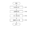
- FIG. 6 is a flowchart showing the process of the blow molding method.
- Step S101 Injection molding step
- resin is injected from the injection device 25 into the preform-shaped mold space formed by the injection cavity type, the injection core type, and the neck type 27 of the transport mechanism 26, and the preform 11 is manufactured. ..
- step S101 the injection molding portion 21 is opened immediately after the resin filling is completed or after the minimum cooling time provided after the resin filling. That is, the preform 11 is released from the injection cavity type and the injection core type at a high temperature state at which the outer shape of the preform 11 can be maintained. After that, the rotating plate of the transport mechanism 26 rotates by a predetermined angle, and the preform 11 held by the neck mold 27 is transported to the temperature adjusting unit 22.
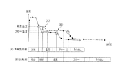
- FIG. 7 shows the temperature change of the preform 11 in the blow molding method of the present embodiment.
- the vertical axis of FIG. 7 shows the temperature of the preform 11, and the horizontal axis of FIG. 7 shows the time.
- FIG. 7 an example of a temperature change of the preform of the present embodiment is shown in FIG. 7 (A).
- FIG. 7 (B) an example of temperature change of the preform of the comparative example (conventional method) described later is shown in FIG. 7 (B).
- the blank space between the steps is the time required for transferring the preform 11 or the container 10, and is the same.
- the injection-molding unit 21 when the resin material is injection-molded at a temperature equal to or higher than the melting point of the resin material, the injection-molding unit 21 performs only the minimum cooling of the preform 11 after the injection molding, and the temperature adjusting unit 22 performs injection molding. Cooling and temperature adjustment of the reform 11 are performed.
- the time (cooling time) for cooling the resin material after the injection of the resin material is completed in the injection molding unit 21 is 1/2 or less of the time (injection time) for injecting the resin material. Is preferable. Further, the time for cooling the resin material can be made shorter than the time for injecting the resin material, depending on the weight of the resin material.
- the time for cooling the resin material is more preferably 2/5 or less, further preferably 1/4 or less, and particularly preferably 1/5 or less with respect to the time for injecting the resin material. Since the cooling time is significantly shortened compared to the comparative example, the preform skin layer (surface layer in the solidified state) is thinner than before, and the core layer (inner layer in softened or melted state) is thicker than before. It is formed. That is, as compared with the comparative example, a preform having a large heat gradient between the skin layer and the core layer and having a high heat retention at a high temperature is formed.
- the injection-molded preform 11 is released from the injection-molded portion 21 at a higher mold-release temperature than in the case of the comparative example, and is conveyed to the temperature adjusting portion 22.
- the temperature of the preform 11 is equalized by heat exchange (heat conduction) between the skin layer and the core layer. Further, the preform 11 is slightly cooled from the outer surface by contact with the outside air. However, the temperature of the preform 11 is maintained in a state of a substantially high mold release temperature until it is carried into the temperature adjusting unit 22.
- the temperature of the preform 11 is lowered from the high mold release temperature to the blow temperature, and then the temperature of the preform 11 is maintained at the blow temperature until the blow molding is performed.
- the blow temperature is a temperature suitable for blow molding, and is set to, for example, 90 ° C to 105 ° C for PET resin.
- the blow temperature is preferably set to 90 ° C. to 95 ° C. for PET resin.
- each time of the injection molding step, the temperature adjusting step, the blow molding step, and the container taking-out step has the same length.
- the transport time between each step is the same length.
- the preform 11 is cooled to a temperature lower than or substantially the same as the blow temperature in the mold of the injection molding unit 21.
- the time of the injection molding step becomes longer than that of the present embodiment. Then, since the time of each process is set according to the time of the longest injection molding process, the time of the molding cycle of the container also becomes long as a result.
- Step S102 Temperature adjustment step
- the temperature adjusting unit 22 performs temperature adjustment for bringing the temperature of the preform 11 closer to a temperature suitable for the final blow.
- the preform 11 is housed in the temperature adjustment space of the preform shape of the cavity type 31.
- the core mold 32 is inserted into the preform 11 housed in the cavity mold 31. Since the cavity mold 31 and the core mold correspond to the shape of the preform 11, the shape of the preform is maintained as a desired shape even in the temperature adjustment step.
- the temperature adjustment step when the preform 11 comes into contact with the cavity mold and the core mold, the temperature of the preform 11 is adjusted so as not to fall below the temperature suitable for blow molding, and the uneven temperature generated during injection molding is also adjusted. It will be reduced.
- the first flow path 43a and the second flow path 43b are formed in a spiral shape.
- the temperature adjusting medium in the core mold 32 flows in the circumferential direction, which promotes heat conduction in the circumferential direction in the core mold 32, and causes the temperature deviation of the preform 11 in contact with the core mold 32 in the circumferential direction. It can be significantly reduced.
- the air in the preform 11 is guided from the exhaust port 40 to the exhaust passage 41 through the exhaust chamber 42 in the core pin. It is exhausted to the outside. Therefore, when the core mold 32 is inserted into the preform 11, for example, it is possible to prevent an air pool from being generated between the core mold 32 and the core mold 32 on the bottom surface or the side surface of the preform 11. As a result, the contact area between the inner peripheral surface of the preform 11 and the core mold 32 is further expanded, so that the efficiency of additional cooling and temperature deviation adjustment of the preform 11 by the core mold 32 can be further improved.
- the exhaust passage 41 of the core mold 32 is arranged on the inner peripheral side of the flow path 43 of the temperature adjusting medium. That is, since the exhaust passage 41 is not located between the preform 11 and the flow path 43 of the temperature adjusting medium, the temperature adjusting medium flowing through the preform 11 and the core mold 32 in contact with the core mold 32 is located. Heat conduction is not hindered by being insulated by the exhaust passage 41.
- the rotating plate of the transfer mechanism 26 rotates by a predetermined angle, and the temperature-adjusted preform 11 held by the neck mold 27 is conveyed to the blow molding unit 23.
- Step S103 Blow molding step
- the blow molding unit 23 performs blow molding of the container.
- the blow molding mold is closed to accommodate the preform 11 in the mold space, and the air introduction member is inserted into the neck portion 12 of the preform 11.
- blow air is introduced into the preform 11 from the air introduction member while lowering the air introduction member having the extension rod.
- the preform 11 is bulged and shaped so as to be in close contact with the mold space of the blow molding die, and is blow molded into the container.
- a hot parison type preform is molded using a crystalline thermoplastic resin (a resin that can be in a transparent amorphous state and a cloudy crystalline state) as a material
- some materials are whitened (whitened) due to insufficient cooling. It may end up.
- PET resin a resin that can be in a transparent amorphous state and a cloudy crystalline state
- some materials are whitened (whitened) due to insufficient cooling. It may end up.
- PET resin is used as a material
- the preform is slowly cooled (for example, cooled at room temperature for a dozen seconds) in a temperature range (120 ° C. to 200 ° C.) where crystallization is promoted, crystallization due to spherulite formation occurs. Shows a tendency to bleach.
- the injection molding mold of the preform is rapidly cooled (for example, at 10 ° C. for 5 seconds) to shorten the passage time in the above crystallization temperature zone, and the preform is sufficiently cooled in the injection molding step to whiten the preform. Was suppressed.
- the cooling step of the preform 11 is almost eliminated in the injection molding step (S101), and the preform 11 is cooled in the temperature adjusting step (S102).
- the preform 11 can be brought into close contact with the cavity mold 31 and the core mold 32, and the preform 11 can be cooled at the same time as the temperature of the preform 11 is adjusted.
- the preform 11 can be demolded even in a high temperature state in the injection molding step (S101), and the next preform can be removed.
- the molding of 11 can be started early. That is, according to the present embodiment, the container can be molded satisfactorily while shortening the molding cycle time to that of the molding cycle time of the comparative example.
- the tip of the core mold 32 is provided with an exhaust port 40 for discharging air from the inside of the preform 11 through the exhaust passage 41 inside the core mold 32.
- the air inside the preform 11 can be discharged to the outside.
- the contact area between the inner peripheral surface of the preform 11 and the core mold 32 is widened, and the preform in a high temperature state by the core mold 32
- the efficiency of the additional cooling and the temperature deviation adjustment of 11 can be further improved. Since the above effects are the same regardless of the shape of the preform 11, for example, even if the preform 11 has an elongated shape that is difficult to degas, the efficiency of additional cooling and temperature deviation adjustment can be improved.
- the time of the temperature adjustment process is also shortened, and it becomes necessary to further improve the efficiency of heat exchange between the core mold 32 and the preform 11.
- the efficiency of additional cooling and uneven temperature adjustment of the preform 11 in a high temperature state by the core mold 32 is further improved by forming the exhaust port 40 and the exhaust passage 41, and therefore, in the temperature adjustment step (S102).
- the temperature can be adjusted in a short time. That is, the molding cycle can be shortened without deteriorating the quality of the manufactured container.
- the second embodiment is a modification of the first embodiment.
- the same elements as those of the first embodiment are designated by the same reference numerals, and duplicate description will be omitted.
- the configuration of the mold unit 30 of the temperature adjusting unit 22 is different.
- FIG. 8 is a diagram showing a configuration example of the temperature control unit of the second embodiment.
- the temperature adjusting unit 22 has a mold unit 30 for adjusting the temperature.
- the mold unit 30 is an example of a cooling mold unit, and includes a cavity mold (temperature control pot) 31 capable of accommodating the preform 11 and a core mold 32.
- the configuration of the cavity type 31 is the same as that of the first embodiment.
- the core mold 32 is a mold inserted inside the preform 11, and is arranged so as to be able to advance and retreat with respect to the neck mold 27 holding the preform 11 in the temperature adjusting unit 22.
- FIG. 8 shows a state in which the core mold 32 extends downward in the figure and is inserted into the neck mold 27.
- the core mold 32 includes a core pin 34, a main body 35, and a cooling pipe 36.
- the core pin 34 is a bottomed tubular rod-shaped member inserted into the preform 11, and has an outer shape substantially the same as the internal shape of the preform 11. Further, inside the core pin 34, a cylindrical internal space for flowing the temperature adjusting medium is formed along the axial direction.
- the main body 35 is a member connected to a drive mechanism (not shown) that drives the core mold 32 forward and backward, and a core pin 34 is connected to the tip end side of the main body 35.
- a cylindrical internal space corresponding to the inner diameter of the core pin 34 is formed along the axial direction.
- the internal space of the main body 35 is connected to the introduction path 35a of the temperature adjusting medium.
- the internal spaces of the main body 35 and the core pin 34 are coaxially connected to form one liquid-tight (watertight) cylindrical space in the core mold 32. ..
- the cooling pipe 36 is a tubular member inserted into the internal space of the core mold 32, and has a function of partitioning the flow of the temperature adjusting medium from the introduction path 35a.
- the outer diameter of the cooling pipe 36 is smaller than the internal space of the core mold 32, and the axial length of the cooling pipe 36 is set to substantially the same dimension as the axial length of the internal space of the core mold 32. ..
- the internal space of the core mold 32 is axial to the first flow path 43 on the outer peripheral side of the cooling pipe 36 and the second flow path 41 on the inner peripheral side of the cooling pipe 36 in a state where the cooling pipe is inserted. It is partitioned along the direction.
- the first flow path 43 and the second flow path 41 communicate with each other on the tip end side of the cooling pipe 36 facing the inner bottom of the core pin 34.
- the first flow path 43 is connected to the introduction path 35a of the temperature control medium in the main body 35, and the second flow path 41 is connected to the discharge path of the temperature control medium (not shown).
- the temperature adjusting medium flows from the introduction path 35a of the main body 35 toward the tip end side of the core mold 32 through the first flow path 43, and from the tip end side of the core mold 32.
- the temperature adjusting medium folds back and flows through the second flow path 41 in the cooling pipe 36.
- the core mold 32 is kept at a predetermined temperature by such a flow of the temperature adjusting medium.
- the flow of the temperature adjusting medium is an example, and the temperature adjusting medium may flow from the second flow path 41 side by reversing the flow of the temperature adjusting medium.
- an exhaust groove 34a extending from the tip end side of the core pin 34 inserted into the preform 11 to the base end portion not inserted into the preform 11 is provided.
- the exhaust groove 34a has a function of discharging the air inside the preform 11 to the outside of the preform 11 when the core mold 32 is inserted into the preform 11, and improving the contact between the core mold 32 and the preform 11. Take on.
- FIG. 9 is a diagram showing an example of forming the exhaust groove 34a in the present embodiment.
- the core pin 34 of the present embodiment is formed with a plurality of linear exhaust grooves 34a along the axial direction of the core pin 34.
- four exhaust grooves 34a are formed, for example, at equal intervals of 90 ° in the circumferential direction of the core pin.
- the number and arrangement intervals of the exhaust grooves 34a can be appropriately changed.
- the shape of the cross section of the exhaust groove 34a is not particularly limited as long as the air between the preform 11 and the core pin 34 can be degassed, and for example, any of V-shape, rectangular shape, semicircular shape and the like. It may be in shape.
- the core pin 34 may have only one exhaust groove 34a, but if a plurality of exhaust grooves 34a are formed in the core pin 34, air can be discharged from a plurality of locations when the core mold 32 is inserted into the preform 11, and the core The uneven contact between the mold 32 and the preform 11 is less likely to occur.
- the size of the groove width of each exhaust groove 34a is not particularly limited, but is set to, for example, 0.02 mm or more and 0.2 mm or less.
- the groove width of the exhaust groove 34a becomes large, the marks of the exhaust groove 34a become conspicuous in the container shaped from the preform 11. Therefore, from the viewpoint of forming a good container in which the marks of the exhaust groove 34a are inconspicuous, the groove width of the exhaust groove 34a is preferably 0.2 mm or less.
- the smaller the groove width of the exhaust groove 34a the higher the processing cost of the exhaust groove 34a, although it becomes difficult to discharge air. Therefore, from the viewpoint of keeping the processing cost within a practical range while maintaining the function of the exhaust groove 34a, the groove width of the exhaust groove 34a is preferably 0.02 mm or more.
- each exhaust groove 34a is not particularly limited, but is set to, for example, 0.02 mm or more and 3 mm or less. From the viewpoint of ensuring the function of discharging air in the exhaust groove 34a, the groove depth of the exhaust groove 34a is preferably 0.02 mm or more. On the other hand, if the groove depth of the exhaust groove 34a is increased, air can be easily discharged, but in order to form the exhaust groove 34a, it becomes necessary to make the core pin 34 thicker by that amount, and the preform 11 by the core mold 32 Cooling efficiency can be reduced. Therefore, the groove depth of the exhaust groove 34a is preferably 3 mm or less so that the wall thickness of the core pin 34 does not need to be thicker than necessary.
- any method can be adopted from the known processing techniques according to the material of the core pin 34.
- one end of the columnar end mill 50 is pressed against the peripheral surface of the core pin 34 from an oblique direction in a top view, and the end mill 50 is moved relative to the core pin 34 in the axial direction.
- An exhaust groove 34a may be formed in the core pin 34. According to the processing method of FIG. 11A, the exhaust groove 34a can be easily formed at a relatively low cost.
- a tapered rotary cutting tool 51 corresponding to the shape of the exhaust groove 34a is prepared, and the rotary cutting tool 51 is vertically pressed against the peripheral surface of the core pin 34 to form the core pin.
- the exhaust groove 34a may be formed by moving the rotary cutting tool 51 relative to the axis 34 in the axial direction.
- the saw blade 52 rotating along the axial direction of the core pin 34 may be pressed against the peripheral surface of the core pin 34 to form the exhaust groove 34a.
- the process of the blow molding method in the second embodiment is the same as that in the first embodiment except for the temperature adjustment step (S102 in FIG. 6).
- the air inside the preform 11 passes through the exhaust groove 34a of the core pin 34 and is outside the preform 11. Is discharged to. Therefore, when the core mold 32 is inserted into the preform 11, for example, it is possible to prevent an air pool from being generated between the core mold 32 and the core mold 32 on the bottom surface or the side surface of the preform 11. As a result, the contact area between the inner peripheral surface of the preform 11 and the core mold 32 is further expanded, so that the efficiency of additional cooling and temperature deviation adjustment of the preform 11 by the core mold 32 can be further improved.
- the container by cooling the preform 11 in the temperature adjustment step (S102), the container can be satisfactorily molded while shortening the molding cycle time as in the first embodiment. ..
- the surface of the core mold 32 facing the inner surface of the preform 11 is provided with an exhaust groove 34a extending from the tip end side to the base end side of the core pin 34.
- the contact area between the inner peripheral surface of the preform 11 and the core mold 32 is widened, and the preform in a high temperature state by the core mold 32
- the efficiency of the additional cooling and the temperature deviation adjustment of 11 can be further improved. Since the above effects are the same regardless of the shape of the preform 11, for example, even if the preform 11 has an elongated shape that is difficult to degas, the efficiency of additional cooling and temperature deviation adjustment can be improved.
- the time of the temperature adjustment process is also shortened, and it becomes necessary to further improve the efficiency of heat exchange between the core mold 32 and the preform 11.
- the efficiency of additional cooling and uneven temperature adjustment of the preform 11 in the high temperature state by the core mold 32 is further improved by forming the exhaust groove 34a, so that the temperature adjustment step (S102) can be performed in a short time.
- the temperature can be adjusted. That is, the molding cycle can be shortened without deteriorating the quality of the manufactured container.
- the preform 11 in a high temperature state is easily deformed following the concave portion of the mold, and if the width of the exhaust groove 34a is increased, the mark of the exhaust groove 34a becomes conspicuous even in the container of the final molded product.
- the groove width dimension of the exhaust groove 34a 0.02 mm or more and 0.2 mm or less, it is possible to obtain a good container in which the marks of the exhaust groove 34a are inconspicuous.
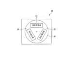
- FIG. 12 is a diagram schematically showing the configuration of the injection molding apparatus 60 of the third embodiment.
- the injection molding apparatus 60 of the present embodiment is an apparatus used for manufacturing the preform 11 at a high speed, and the blow molding unit 23 is removed from the blow molding apparatus 20 of the first embodiment or the second embodiment.
- the same reference numerals are given to the same configurations as those in the first embodiment or the second embodiment, and duplicate description will be omitted.
- the injection molding device 60 includes an injection molding unit 21, a temperature adjusting unit (a temperature adjusting unit for cooling the preform 11 and a post-cooling unit) 22, a take-out unit 24, and a rotating plate 61 as a transport mechanism.
- the injection molding apparatus 60 of the third embodiment has a mold unit 30 similar to that of the first embodiment or the second embodiment in the temperature adjusting unit 22.
- the injection molding unit 21, the temperature adjusting unit 22, and the taking-out unit 24 are arranged at positions rotated by a predetermined angle (for example, 120 degrees) in the circumferential direction of the rotating plate 61.
- the configuration of the rotary plate 61 is the same as that of the transport mechanism of the first embodiment except that the rotation angle for each step is different.
- the preform 11 in which the neck portion 12 is held by the neck mold 27 is conveyed in the order of the injection molding portion 21, the temperature adjusting portion 22, and the taking-out portion 24 by the rotation of the rotating plate 61.
- the preform 11 is provided in the temperature adjusting unit 22. Additional cooling can be done.
- the injection molding unit 21 heats the preform 11 at a high temperature as in the first embodiment or the second embodiment ((A) main embodiment of FIG. 7).
- the mold can be released even in the state, and the cooling time of the preform 11 in the injection molding unit 21 can be significantly shortened.
- the molding of the next preform 11 can be started early, so that the molding cycle time of the preform 11 can be shortened.
- the effect of the temperature adjusting unit 22 described in the first embodiment or the second embodiment can be similarly obtained.
- the temperature adjusting unit 22 preforms so that whitening (white turbidity), sink marks, and irregular deformation do not occur at room temperature. It is necessary to cool the preform 11 until it is completely solidified (the temperature of the preform 11 needs to be cooled to a temperature equal to or lower than the optimum temperature for blowing (for example, 50 ° C. or lower)). Therefore, the mold unit 30 and the cavity mold 31 are set to a low temperature by a low temperature (for example, 0 to 20 ° C.) temperature adjusting medium.
- the present invention is not limited to the above embodiment, and various improvements and design changes may be made without departing from the spirit of the present invention.
- the example in which the first flow path 43a and the second flow path 43b of the temperature control medium in the core mold 32 are both formed in the same layer of the core mold 32 has been described.
- the inside of the core mold 32 may have a three-layer structure, and the first flow path 43a and the second flow path 43b may be arranged in different layers in the radial direction.
- the exhaust groove 34a of the second embodiment is not limited to the one formed linearly along the axial direction of the core pin 34, and may have another pattern.
- FIG. 13A shows an example in which the exhaust groove 34a is spirally formed in the core pin 34. Even when the exhaust grooves 34a are formed in a spiral shape, it is preferable to form a plurality of exhaust grooves 34a on the core pin 34 and arrange each exhaust groove 34a at a rotationally symmetrical position.
- FIG. 13B shows an example in which a plurality of exhaust grooves 34a are formed in the core pin 34 so as to intersect each other.
- the exhaust grooves 34a intersect at a plurality of points between the tip end side and the base end side of the core pin 34. Therefore, for example, even if a partial clogging occurs in one of the exhaust grooves 34a, air can be passed through another intersecting exhaust groove 34a, and the core mold 32 is inserted into the preform 11. The air in the preform 11 can be discharged more reliably when the operation is performed.
Abstract
Provided is a molding unit for cooling an injection-molded bottomed resinous preform, the molding unit being provided with a core mold having a contour corresponding to an inner shape of the preform and insertable into an inside of the preform. A tip end of the core mold that faces a bottom part of the preform has an exhaust opening for exhausting air from an inside of the preform via an inner part of the core mold.
Description
本発明は、樹脂成形品の冷却用金型ユニット、ブロー成形装置、射出成形装置および方法に関する。
The present invention relates to a mold unit for cooling a resin molded product, a blow molding device, an injection molding device, and a method.
従来から樹脂製容器の製造装置の一つとして、ホットパリソン式のブロー成形装置が知られている。ホットパリソン式のブロー成形装置は、プリフォームの射出成形時の保有熱を利用して樹脂製容器をブロー成形する構成であり、コールドパリソン式と比較して多様かつ美的外観に優れた樹脂製容器を製造できる点で有利である。
Conventionally, a hot parison type blow molding device has been known as one of the manufacturing devices for resin containers. The hot parison type blow molding device has a configuration in which a resin container is blow molded by utilizing the heat retained during injection molding of the preform, and is a resin container that is more diverse and has an excellent aesthetic appearance as compared with the cold parison type. It is advantageous in that it can be manufactured.
例えば、ホットパリソン式のブロー成形サイクルや、プリフォームの射出成形サイクルに関しては、成形サイクルの短縮を目的として種々の提案がなされている。これらの成形サイクルの短縮化のために、律速段階であるプリフォームの射出成形時間(射出金型でのプリフォームの冷却時間)を短縮し、射出成形後の下流工程で高熱のプリフォームの追加冷却を行うことが提案されている(例えば特許文献1参照)。
For example, regarding the hot parison type blow molding cycle and the injection molding cycle of preform, various proposals have been made for the purpose of shortening the molding cycle. In order to shorten these molding cycles, the injection molding time of the preform, which is the rate-determining stage (cooling time of the preform in the injection mold), is shortened, and a high-heat preform is added in the downstream process after the injection molding. It has been proposed to perform cooling (see, for example, Patent Document 1).
また、プリフォームをキャビティ金型およびコア金型と接触させて金型との熱交換でプリフォームを冷却するとともに、プリフォームの偏温の調整を行う構成も提案されている(例えば特許文献2参照)。
Further, a configuration has also been proposed in which the preform is brought into contact with the cavity mold and the core mold to cool the preform by heat exchange with the mold, and at the same time, the uneven temperature of the preform is adjusted (for example, Patent Document 2). reference).
コア金型との接触により高温状態のプリフォームの追加冷却を行う場合、プリフォームと金型を均等に接触させる必要がある。例えば、冷却対象のプリフォームにコア金型を挿入する際にプリフォーム内に空気が残ると、プリフォームの内周面とコア金型の接触が妨げられ、プリフォームの冷却や温度調整を適切に行うことが困難となる。
When performing additional cooling of the preform in a high temperature state by contact with the core mold, it is necessary to make the preform and the mold evenly contact. For example, if air remains in the preform when the core mold is inserted into the preform to be cooled, the contact between the inner peripheral surface of the preform and the core mold is hindered, and the preform is properly cooled and the temperature is adjusted. It becomes difficult to do.
そこで、本発明はこのような課題に鑑みてなされたものであり、高温状態のプリフォームの追加冷却や温度調整の効率を向上できる冷却用金型ユニットを提供することを目的とする。
Therefore, the present invention has been made in view of such a problem, and an object of the present invention is to provide a cooling mold unit capable of improving the efficiency of additional cooling and temperature adjustment of a preform in a high temperature state.
本発明の一態様は、射出成形された有底形状の樹脂製のプリフォームを冷却するための冷却用金型ユニットであって、プリフォームの内部形状に対応する外形を有し、プリフォームの内部に挿入可能なコア金型を備え、プリフォームの底部に臨むコア金型の先端部には、コア金型の内部を介してプリフォーム内から空気を排出する排気口が設けられている。
One aspect of the present invention is a cooling mold unit for cooling an injection-molded bottomed resin preform, which has an outer shape corresponding to the internal shape of the preform and is a preform. A core mold that can be inserted inside is provided, and an exhaust port that exhausts air from the inside of the preform through the inside of the core mold is provided at the tip of the core mold that faces the bottom of the preform.
本発明の他の態様は、射出成形された有底形状の樹脂製のプリフォームを冷却するための冷却用金型ユニットであって、プリフォームの内部形状に対応する外形を有し、プリフォームの内部に挿入可能なコア金型を備え、コア金型においてプリフォームの内面に臨む表面には、プリフォームの挿入部分の先端側から基端側にわたって延びる排気溝が設けられている。
Another aspect of the present invention is a cooling mold unit for cooling an injection-molded bottomed resin preform, which has an outer shape corresponding to the internal shape of the preform and has a preform. A core mold that can be inserted into the inside of the core mold is provided, and an exhaust groove extending from the tip end side to the base end side of the preform insertion portion is provided on the surface of the core mold that faces the inner surface of the preform.
本発明によれば、高温状態のプリフォームの追加冷却や温度調整の効率を向上することができる。
According to the present invention, it is possible to improve the efficiency of additional cooling and temperature adjustment of the preform in a high temperature state.
以下、本発明の実施形態について図面を参照して説明する。
実施形態では説明を分かり易くするため、本発明の主要部以外の構造や要素については、簡略化または省略して説明する。また、図面において、同じ要素には同じ符号を付す。なお、図面に示す各要素の形状、寸法などは模式的に示したもので、実際の形状、寸法などを示すものではない。 Hereinafter, embodiments of the present invention will be described with reference to the drawings.
In the embodiment, in order to make the description easy to understand, the structures and elements other than the main part of the present invention will be described in a simplified or omitted manner. Further, in the drawings, the same elements are designated by the same reference numerals. The shapes and dimensions of each element shown in the drawings are schematically shown, and do not indicate the actual shapes and dimensions.
<第1実施形態>
図1は、第1実施形態のブロー成形装置20の構成を模式的に示す図である。本実施形態のブロー成形装置20は、プリフォーム11を室温まで冷却せずに射出成形時の保有熱(内部熱量)を活用して容器をブロー成形するホットパリソン方式(1ステージ方式とも称する)の装置である。 <First Embodiment>
FIG. 1 is a diagram schematically showing the configuration of theblow molding apparatus 20 of the first embodiment. The blow molding apparatus 20 of the present embodiment is of a hot parison method (also referred to as a one-stage method) in which a container is blow-molded by utilizing the retained heat (internal heat amount) at the time of injection molding without cooling the preform 11 to room temperature. It is a device.
図1は、第1実施形態のブロー成形装置20の構成を模式的に示す図である。本実施形態のブロー成形装置20は、プリフォーム11を室温まで冷却せずに射出成形時の保有熱(内部熱量)を活用して容器をブロー成形するホットパリソン方式(1ステージ方式とも称する)の装置である。 <First Embodiment>
FIG. 1 is a diagram schematically showing the configuration of the
ブロー成形装置20は、射出成形部21と、温度調整部22と、ブロー成形部23と、取り出し部24と、搬送機構26とを備える。射出成形部21、温度調整部22、ブロー成形部23および取り出し部24は、搬送機構26を中心として所定角度(例えば90度)ずつ回転した位置に配置されている。
The blow molding device 20 includes an injection molding unit 21, a temperature adjusting unit 22, a blow molding unit 23, a take-out unit 24, and a transport mechanism 26. The injection molding unit 21, the temperature adjusting unit 22, the blow molding unit 23, and the take-out unit 24 are arranged at positions rotated by a predetermined angle (for example, 90 degrees) about the transport mechanism 26.
(搬送機構26)
搬送機構26は、図1の紙面垂直方向の軸を中心に回転する回転板(不図示)を備える。回転板には、プリフォーム11または樹脂製容器(以下、単に容器と称する)の首部12を保持するネック型27(図1では不図示)が、所定角度ごとにそれぞれ1以上配置されている。搬送機構26は、回転板を回転させることで、ネック型27で首部12が保持されたプリフォーム11(または容器)を、射出成形部21、温度調整部22、ブロー成形部23、取り出し部24の順に搬送する。なお、搬送機構26は、回転板を昇降させることもでき、射出成形部21におけるプリフォームの型閉じや型開き(離型)に係る動作も行う。 (Transport mechanism 26)
Thetransport mechanism 26 includes a rotating plate (not shown) that rotates about an axis in the direction perpendicular to the paper surface of FIG. 1. On the rotating plate, one or more neck molds 27 (not shown in FIG. 1) holding the neck portion 12 of the preform 11 or the resin container (hereinafter, simply referred to as a container) are arranged at each predetermined angle. By rotating the rotating plate, the transport mechanism 26 transfers the preform 11 (or container) in which the neck portion 12 is held by the neck mold 27 to the injection molding portion 21, the temperature adjusting portion 22, the blow molding portion 23, and the take-out portion 24. Transport in the order of. The transport mechanism 26 can also raise and lower the rotating plate, and also performs operations related to mold closing and mold opening (release) of the preform in the injection molding unit 21.
搬送機構26は、図1の紙面垂直方向の軸を中心に回転する回転板(不図示)を備える。回転板には、プリフォーム11または樹脂製容器(以下、単に容器と称する)の首部12を保持するネック型27(図1では不図示)が、所定角度ごとにそれぞれ1以上配置されている。搬送機構26は、回転板を回転させることで、ネック型27で首部12が保持されたプリフォーム11(または容器)を、射出成形部21、温度調整部22、ブロー成形部23、取り出し部24の順に搬送する。なお、搬送機構26は、回転板を昇降させることもでき、射出成形部21におけるプリフォームの型閉じや型開き(離型)に係る動作も行う。 (Transport mechanism 26)
The
(射出成形部21)
射出成形部21は、それぞれ図示を省略する射出キャビティ型、射出コア型を備え、図2に示すプリフォーム11を製造する。射出成形部21には、プリフォーム11の原材料である樹脂材料を供給する射出装置25が接続されている。 (Injection molding unit 21)
Theinjection molding unit 21 includes an injection cavity type and an injection core type, which are not shown, respectively, and manufactures the preform 11 shown in FIG. An injection device 25 that supplies a resin material that is a raw material of the preform 11 is connected to the injection molding unit 21.
射出成形部21は、それぞれ図示を省略する射出キャビティ型、射出コア型を備え、図2に示すプリフォーム11を製造する。射出成形部21には、プリフォーム11の原材料である樹脂材料を供給する射出装置25が接続されている。 (Injection molding unit 21)
The
射出成形部21においては、上記の射出キャビティ型、射出コア型と、搬送機構26のネック型27とを型閉じしてプリフォーム形状の型空間を形成する。そして、このようなプリフォーム形状の型空間内に射出装置25から樹脂材料を流し込むことで、射出成形部21でプリフォーム11が製造される。
ここで、プリフォーム11の全体形状は、一端側が開口され、他端側が閉塞された有底円筒形状である。プリフォーム11の開口側の端部には、首部12が形成されている。 In theinjection molding unit 21, the injection cavity mold and the injection core mold and the neck mold 27 of the transport mechanism 26 are closed to form a preform-shaped mold space. Then, by pouring the resin material from the injection device 25 into such a preform-shaped mold space, the injection molding unit 21 manufactures the preform 11.
Here, the overall shape of thepreform 11 is a bottomed cylindrical shape in which one end side is open and the other end side is closed. A neck portion 12 is formed at the end portion of the preform 11 on the opening side.
ここで、プリフォーム11の全体形状は、一端側が開口され、他端側が閉塞された有底円筒形状である。プリフォーム11の開口側の端部には、首部12が形成されている。 In the
Here, the overall shape of the
また、容器およびプリフォーム11の材料は、熱可塑性の合成樹脂であり、容器の用途に応じて適宜選択できる。具体的な材料の種類としては、例えば、PET(ポリエチレンテレフタレート)、PEN(ポリエチレンナフタレート)、PCTA(ポリシクロヘキサンジメチレンテレフタレート)、Tritan(トライタン(登録商標):イーストマンケミカル社製のコポリエステル)、PP(ポリプロピレン)、PE(ポリエチレン)、PC(ポリカーボネート)、PES(ポリエーテルスルホン)、PPSU(ポリフェニルスルホン)、PS(ポリスチレン)、COP/COC(環状オレフィン系ポリマー)、PMMA(ポリメタクリル酸メチル:アクリル)、PLA(ポリ乳酸)などが挙げられる。
The material of the container and the preform 11 is a thermoplastic synthetic resin, and can be appropriately selected according to the use of the container. Specific types of materials include, for example, PET (polyethylene terephthalate), PEN (polyethylene naphthalate), PCTA (polycyclohexanedimethylene terephthalate), Tritan (Tritan (registered trademark): copolyester manufactured by Eastman Chemical Co., Ltd.). , PP (polypropylene), PE (polyethylene), PC (polyethylene), PES (polyether sulfone), PPSU (polyphenyl sulfone), PS (polystyrene), COP / COC (cyclic olefin polymer), PMMA (polymethacrylic acid) Methyl: acrylic), PLA (polylactic acid) and the like.
なお、射出成形部21の型開きをしたときにも、搬送機構26のネック型27は開放されずにそのままプリフォーム11を保持して搬送する。射出成形部21で同時に成形されるプリフォーム11の数(すなわち、ブロー成形装置20で同時に成形できる容器の数)は、適宜設定できる。
Even when the injection molding unit 21 is opened, the neck mold 27 of the transport mechanism 26 is not opened and the preform 11 is held and conveyed as it is. The number of preforms 11 simultaneously molded by the injection molding unit 21 (that is, the number of containers that can be simultaneously molded by the blow molding apparatus 20) can be appropriately set.
(温度調整部22)
温度調整部22は、射出成形部21で製造されたプリフォーム11の均温化や偏温除去を行い、プリフォーム11の温度をブロー成形に適した温度(例えば約90℃~105℃)に調整する。また、温度調整部22は、射出成形後の高温状態のプリフォーム11を冷却する機能も担う。 (Temperature control unit 22)
Thetemperature adjusting unit 22 equalizes the temperature of the preform 11 manufactured by the injection molding unit 21 and removes the uneven temperature, and brings the temperature of the preform 11 to a temperature suitable for blow molding (for example, about 90 ° C. to 105 ° C.). adjust. The temperature adjusting unit 22 also has a function of cooling the preform 11 in a high temperature state after injection molding.
温度調整部22は、射出成形部21で製造されたプリフォーム11の均温化や偏温除去を行い、プリフォーム11の温度をブロー成形に適した温度(例えば約90℃~105℃)に調整する。また、温度調整部22は、射出成形後の高温状態のプリフォーム11を冷却する機能も担う。 (Temperature control unit 22)
The
図2に示すように、温度調整部22は、温度調整用の金型ユニット30を有する。金型ユニット30は、冷却用金型ユニットの一例であって、プリフォーム11を収容可能なキャビティ型(温調ポット)31と、コア金型32とを備える。
As shown in FIG. 2, the temperature adjusting unit 22 has a mold unit 30 for temperature adjusting. The mold unit 30 is an example of a cooling mold unit, and includes a cavity mold (temperature control pot) 31 capable of accommodating the preform 11 and a core mold 32.
キャビティ型31は、射出成形部21で製造されたプリフォーム11の外形と略同じ形状の温度調整用の空間を有する金型であって、支持台33の上に配置されている。本実施形態のキャビティ型31は、上段型31aと下段型31bとを有し、上下2段に分割された構成である。
The cavity mold 31 is a mold having a space for temperature adjustment having substantially the same shape as the outer shape of the preform 11 manufactured by the injection molding unit 21, and is arranged on the support base 33. The cavity type 31 of the present embodiment has an upper stage type 31a and a lower stage type 31b, and is divided into upper and lower stages.
上段型31aおよび下段型31bのそれぞれの内部には、温度調整媒体(冷却媒体)の流れる流路(不図示)が形成されている。そのため、キャビティ型31の温度は、上段型31aおよび下段型31bの内部に流れる温度調整媒体により所定の温度に保たれる。上段型31aと下段型31bの温度調整媒体の温度を変更することで、プリフォーム11の温度分布をプリフォーム11の長手方向に変化させてもよい。
なお、キャビティ型31の温度調整媒体の温度は特に限定されるものではないが、例えば、5℃~80℃、好ましくは30℃から60℃の間の範囲内で適宜選択することが可能である。 Inside each of theupper type 31a and the lower type 31b, a flow path (not shown) through which the temperature adjusting medium (cooling medium) flows is formed. Therefore, the temperature of the cavity type 31 is maintained at a predetermined temperature by the temperature adjusting medium flowing inside the upper type 31a and the lower type 31b. By changing the temperature of the temperature adjusting medium of the upper mold 31a and the lower mold 31b, the temperature distribution of the preform 11 may be changed in the longitudinal direction of the preform 11.
The temperature of the temperature adjusting medium of thecavity type 31 is not particularly limited, but can be appropriately selected within the range of, for example, 5 ° C. to 80 ° C., preferably 30 ° C. to 60 ° C. ..
なお、キャビティ型31の温度調整媒体の温度は特に限定されるものではないが、例えば、5℃~80℃、好ましくは30℃から60℃の間の範囲内で適宜選択することが可能である。 Inside each of the
The temperature of the temperature adjusting medium of the
ここで、キャビティ型31の構成は、本実施形態の構成に限定されることはない。例えば、キャビティ型31は上下に3段に分かれた構成としてもよい。また、例えば、キャビティ型31は、プリフォーム11の長手方向に分割される一対の割型で構成されていてもよい。
Here, the configuration of the cavity type 31 is not limited to the configuration of the present embodiment. For example, the cavity type 31 may be configured to be divided into three upper and lower stages. Further, for example, the cavity mold 31 may be composed of a pair of split molds divided in the longitudinal direction of the preform 11.
コア金型32は、プリフォーム11の内部に挿入される金型であって、温度調整部22でプリフォーム11を保持しているネック型27に対して進退可能に配置される。図2では、コア金型32が図中下側に伸張してネック型27の内部に挿入された状態を示している。
The core mold 32 is a mold inserted inside the preform 11, and is arranged so as to be able to advance and retreat with respect to the neck mold 27 holding the preform 11 in the temperature adjusting unit 22. FIG. 2 shows a state in which the core mold 32 extends downward in the figure and is inserted into the neck mold 27.
コア金型32は、コアピン(第1のコア金型)34と、本体部(第2のコア金型)35と、冷却パイプ36とを少なくとも備える。
コアピン34は、プリフォーム11に挿入される有底筒状の棒状部材であり、プリフォーム11の内部形状と略同じ形状の外形を有する。また、コアピン34の内部には、温度調整媒体を流すための円筒状の内部空間が軸方向に沿って形成されている。 Thecore mold 32 includes at least a core pin (first core mold) 34, a main body portion (second core mold) 35, and a cooling pipe 36.
Thecore pin 34 is a bottomed tubular rod-shaped member inserted into the preform 11, and has an outer shape substantially the same as the internal shape of the preform 11. Further, inside the core pin 34, a cylindrical internal space for flowing the temperature adjusting medium is formed along the axial direction.
コアピン34は、プリフォーム11に挿入される有底筒状の棒状部材であり、プリフォーム11の内部形状と略同じ形状の外形を有する。また、コアピン34の内部には、温度調整媒体を流すための円筒状の内部空間が軸方向に沿って形成されている。 The
The
プリフォーム11の底面に臨むコアピン34の先端には、コアピン34の内部空間に連通する排気口40が形成されている。コアピン34の排気口40は、コア金型32をプリフォーム11に挿入するときに、プリフォーム11内の空気をコアピン34内に排出し、コア金型32とプリフォーム11の接触性を向上させる機能を担う。
An exhaust port 40 communicating with the internal space of the core pin 34 is formed at the tip of the core pin 34 facing the bottom surface of the preform 11. The exhaust port 40 of the core pin 34 discharges the air in the preform 11 into the core pin 34 when the core mold 32 is inserted into the preform 11, and improves the contact between the core mold 32 and the preform 11. Take on the function.
排気口40は、コア金型32(より具体的にはコアピン34)の中心軸を基準として、コア金型32(より具体的にはコアピン34)の周方向に回転対称をなす形状で形成されている。コア金型32(より具体的にはコアピン34)の周方向に回転対称をなすように排気口40を形成すると、プリフォーム11内の空気を周方向にむらなく均等に排出しやすくなるので、コア金型32とプリフォーム11の接触の偏りがより生じにくくなる。例えば、図4(A)では、4つの排気口40が、90度の間隔で点対称をなすように周方向に間隔をあけてコアピン34の先端に形成されている。もっとも、排気口40は、必ずしも回転対称に配置されていなくてもよく、例えば、コア金型32(より具体的にはコアピン34)の先端において、その中心軸から所定距離範囲内にある任意の位置に、複数の排気口40を配置してもよい。
The exhaust port 40 is formed in a shape that is rotationally symmetric in the circumferential direction of the core mold 32 (more specifically, the core pin 34) with reference to the central axis of the core mold 32 (more specifically, the core pin 34). ing. If the exhaust port 40 is formed so as to be rotationally symmetric in the circumferential direction of the core mold 32 (more specifically, the core pin 34), the air in the preform 11 can be easily discharged evenly and evenly in the circumferential direction. The uneven contact between the core mold 32 and the preform 11 is less likely to occur. For example, in FIG. 4A, four exhaust ports 40 are formed at the tips of core pins 34 at intervals of 90 degrees so as to form point symmetry in the circumferential direction. However, the exhaust ports 40 do not necessarily have to be arranged rotationally symmetrically, and for example, at the tip of the core mold 32 (more specifically, the core pin 34), any arbitrary exhaust port 40 within a predetermined distance range from the central axis thereof. A plurality of exhaust ports 40 may be arranged at the positions.
なお、コア金型32の中心軸を基準として回転対称をなす配置であれば、コアピン34に排気口40を設ける数は4以外の数(2つや3つ、あるいはそれ以上の整数)であってもよい。また、コアピン34の中心軸の位置(コアピンの中央)に排気口40を1つ設けるようにしてもよい。
If the arrangement is rotationally symmetric with respect to the central axis of the core mold 32, the number of exhaust ports 40 provided on the core pin 34 is a number other than 4 (an integer of 2 or 3 or more). May be good. Further, one exhaust port 40 may be provided at the position of the central axis of the core pin 34 (center of the core pin).
本体部35は、コア金型32を進退駆動させる駆動機構(不図示)に連結された部材であり、本体部35の先端側にはコアピン34が連結される。本体部35の内部には、コアピン34の内径に対応する円筒状の内部空間が軸方向に沿って形成されている。本体部35の内部空間は、温度調整媒体の導入路35aおよび排出路35bとそれぞれ接続される。また、コアピン34を本体部35に取り付けた状態で、本体部35とコアピン34の各内部空間は同軸に接続され、コア金型32において液密(水密)な1つの円筒状の空間を構成する。
The main body 35 is a member connected to a drive mechanism (not shown) that drives the core mold 32 forward and backward, and a core pin 34 is connected to the tip end side of the main body 35. Inside the main body 35, a cylindrical internal space corresponding to the inner diameter of the core pin 34 is formed along the axial direction. The internal space of the main body 35 is connected to the introduction path 35a and the discharge path 35b of the temperature adjusting medium, respectively. Further, with the core pin 34 attached to the main body 35, the internal spaces of the main body 35 and the core pin 34 are coaxially connected to form one liquid-tight (watertight) cylindrical space in the core mold 32. ..
冷却パイプ36は、コア金型32の内部空間に挿入される筒状の部材である。
冷却パイプ36の外周は、コア金型32の内部空間を軸方向に沿って2つに仕切り、温度調整媒体の流路43を形成する。 The coolingpipe 36 is a tubular member inserted into the internal space of the core mold 32.
The outer circumference of the coolingpipe 36 divides the internal space of the core mold 32 into two along the axial direction to form a flow path 43 of the temperature adjusting medium.
冷却パイプ36の外周は、コア金型32の内部空間を軸方向に沿って2つに仕切り、温度調整媒体の流路43を形成する。 The cooling
The outer circumference of the cooling
図3に示すように、冷却パイプ36の外周には、本体部35に対応する第1の領域36aと、コアピン34に対応する第2の領域36bがそれぞれ軸方向に形成されている。
冷却パイプ36の第1の領域36aは、図3、図4(C)に示すように、内部空間に対応する外径の円を左右両側で切り欠いた長円形状の横断面を有する。また、冷却パイプ36の第2の領域36bでは、図3、図4(B)に示すように、パイプの外周に二条ねじをなす螺旋状の仕切り壁37が形成されている。仕切り壁37の外径は内部空間の内径と対応する寸法に設定されている。 As shown in FIG. 3, afirst region 36a corresponding to the main body 35 and a second region 36b corresponding to the core pin 34 are formed on the outer periphery of the cooling pipe 36 in the axial direction, respectively.
As shown in FIGS. 3 and 4C, thefirst region 36a of the cooling pipe 36 has an oval cross section in which a circle having an outer diameter corresponding to the internal space is cut out on both the left and right sides. Further, in the second region 36b of the cooling pipe 36, as shown in FIGS. 3 and 4B, a spiral partition wall 37 forming a double-threaded screw is formed on the outer periphery of the pipe. The outer diameter of the partition wall 37 is set to a dimension corresponding to the inner diameter of the internal space.
冷却パイプ36の第1の領域36aは、図3、図4(C)に示すように、内部空間に対応する外径の円を左右両側で切り欠いた長円形状の横断面を有する。また、冷却パイプ36の第2の領域36bでは、図3、図4(B)に示すように、パイプの外周に二条ねじをなす螺旋状の仕切り壁37が形成されている。仕切り壁37の外径は内部空間の内径と対応する寸法に設定されている。 As shown in FIG. 3, a
As shown in FIGS. 3 and 4C, the
また、図2、図3に示すように、冷却パイプ36の先端外周には、Oリング38が嵌め込まれた円形の封止部36cが設けられている。封止部36cは、コアピン34の先端側に形成される排気室42と、冷却パイプ36の外周に形成される温度調整媒体の流路43とを軸方向において仕切る機能を担う。また、図3に示すように、冷却パイプ36の軸方向において、封止部36cの近傍には仕切り壁37の形成されていない領域36dが設けられている。
Further, as shown in FIGS. 2 and 3, a circular sealing portion 36c in which the O-ring 38 is fitted is provided on the outer periphery of the tip of the cooling pipe 36. The sealing portion 36c has a function of axially partitioning the exhaust chamber 42 formed on the tip end side of the core pin 34 and the flow path 43 of the temperature adjusting medium formed on the outer periphery of the cooling pipe 36. Further, as shown in FIG. 3, in the axial direction of the cooling pipe 36, a region 36d in which the partition wall 37 is not formed is provided in the vicinity of the sealing portion 36c.
また、冷却パイプの内部には、冷却パイプの一端から他端にかけて軸方向に延びる排気路41が形成されている。排気路41は、コアピン34の排気口40からコアピン34内に流れ込んだ空気をコア金型32の外部に排出する機能を担う。
Further, inside the cooling pipe, an exhaust passage 41 extending in the axial direction from one end to the other end of the cooling pipe is formed. The exhaust passage 41 has a function of discharging the air that has flowed into the core pin 34 from the exhaust port 40 of the core pin 34 to the outside of the core mold 32.
冷却パイプ36がコア金型32に挿入された組立状態において、コアピン34の内部空間の底面側と冷却パイプ36の先端の間には、上記の排気口40および排気路41と接続された排気室42が形成される。これにより、コア金型32をプリフォーム11に挿入するときに、プリフォーム11内の空気は、コアピン34の排気口40から排気室42を介して排気路41に導かれ、外部に排気される。なお、排気室42は、Oリング38により温度調整媒体の流路43に対してシールされる。
In the assembled state in which the cooling pipe 36 is inserted into the core mold 32, the exhaust chamber connected to the exhaust port 40 and the exhaust passage 41 is between the bottom surface side of the internal space of the core pin 34 and the tip of the cooling pipe 36. 42 is formed. As a result, when the core mold 32 is inserted into the preform 11, the air in the preform 11 is guided from the exhaust port 40 of the core pin 34 to the exhaust passage 41 through the exhaust chamber 42 and exhausted to the outside. .. The exhaust chamber 42 is sealed with respect to the flow path 43 of the temperature adjusting medium by the O-ring 38.
また、冷却パイプ36がコア金型32に挿入された組立状態において、コア金型32の内部空間と冷却パイプ36によって軸方向に沿って温度調整媒体の流路43が形成される。温度調整媒体の流路43は、温度調整媒体の導入路35aと接続される第1の流路43aと、温度調整媒体の排出路35bと接続される第2の流路43bを有する。
Further, in the assembled state in which the cooling pipe 36 is inserted into the core mold 32, the internal space of the core mold 32 and the cooling pipe 36 form a flow path 43 of the temperature adjusting medium along the axial direction. The flow path 43 of the temperature control medium has a first flow path 43a connected to the introduction path 35a of the temperature control medium and a second flow path 43b connected to the discharge path 35b of the temperature control medium.
冷却パイプ36の第1の領域36aでは、第1の流路43aは冷却パイプ36に対して図2中右側に形成され、第2の流路43bは冷却パイプ36に対して図2中左側に形成される。
冷却パイプ36の第2の領域36bでは、二条ねじをなす螺旋状の仕切り壁37により、第1の流路43aと第2の流路43bが軸方向に沿って交互に配置される。第2の領域36bでの第1の流路43aおよび第2の流路43bは、冷却パイプ36の外周を螺旋状に巻回するように形成される。 In thefirst region 36a of the cooling pipe 36, the first flow path 43a is formed on the right side in FIG. 2 with respect to the cooling pipe 36, and the second flow path 43b is formed on the left side in FIG. 2 with respect to the cooling pipe 36. It is formed.
In thesecond region 36b of the cooling pipe 36, the first flow path 43a and the second flow path 43b are alternately arranged along the axial direction by the spiral partition wall 37 forming the double thread. The first flow path 43a and the second flow path 43b in the second region 36b are formed so as to spirally wind around the outer circumference of the cooling pipe 36.
冷却パイプ36の第2の領域36bでは、二条ねじをなす螺旋状の仕切り壁37により、第1の流路43aと第2の流路43bが軸方向に沿って交互に配置される。第2の領域36bでの第1の流路43aおよび第2の流路43bは、冷却パイプ36の外周を螺旋状に巻回するように形成される。 In the
In the
また、第1の流路43aと第2の流路43bは、封止部36cの近傍にある領域36dで接続され、コア金型32の先端で温度調整媒体の流れが折り返すように構成されている。本実施形態では、第1の流路43aと第2の流路43bをいずれも冷却パイプ36の外周に形成することで、冷却パイプ36における流路43の加工を容易にできる。
Further, the first flow path 43a and the second flow path 43b are connected by a region 36d in the vicinity of the sealing portion 36c, and the flow of the temperature adjusting medium is folded back at the tip of the core mold 32. There is. In the present embodiment, by forming both the first flow path 43a and the second flow path 43b on the outer periphery of the cooling pipe 36, it is possible to easily process the flow path 43 in the cooling pipe 36.
コア金型32の内部では、本体部35の導入路35aからコア金型32の先端側に向けて温度調整媒体が第1の流路43aを流れ、コア金型32の先端側から本体部35の排出路35bに向けて温度調整媒体が第2の流路43bを流れる。このような温度調整媒体の流れによりコア金型32は所定の温度に保たれる。なお、上記の温度調整媒体の流れは一例であり、温度調整媒体の流れを逆にして第2の流路43b側から温度調整媒体を流してもよい。
なお、コア金型32の温度調整媒体の温度は特に限定されるものではないが、例えば、5℃~80℃、好ましくは30℃から60℃の間の範囲内で適宜選択することが可能である。 Inside thecore mold 32, the temperature adjusting medium flows from the introduction path 35a of the main body 35 toward the tip end side of the core mold 32 through the first flow path 43a, and from the tip end side of the core mold 32 to the main body 35. The temperature adjusting medium flows through the second flow path 43b toward the discharge path 35b. The core mold 32 is kept at a predetermined temperature by such a flow of the temperature adjusting medium. The flow of the temperature adjusting medium is an example, and the temperature adjusting medium may flow from the second flow path 43b side by reversing the flow of the temperature adjusting medium.
The temperature of the temperature adjusting medium of thecore mold 32 is not particularly limited, but can be appropriately selected within the range of, for example, 5 ° C. to 80 ° C., preferably 30 ° C. to 60 ° C. is there.
なお、コア金型32の温度調整媒体の温度は特に限定されるものではないが、例えば、5℃~80℃、好ましくは30℃から60℃の間の範囲内で適宜選択することが可能である。 Inside the
The temperature of the temperature adjusting medium of the
(ブロー成形部23)
図1に戻って、ブロー成形部23は、温度調整部22で温度調整されたプリフォーム11に対してブロー成形を行い、容器を製造する。
ブロー成形部23は、容器の形状に対応した一対の割型であるブローキャビティ型と、延伸ロッドおよびブローコア型を少なくとも有するエア導入部材(いずれも不図示)を備える。ブロー成形部23は、プリフォーム11を延伸ブロー成形することで容器を製造する。 (Blow molding unit 23)
Returning to FIG. 1, theblow molding unit 23 blow-molds the temperature-controlled preform 11 by the temperature adjusting unit 22 to manufacture a container.
Theblow molding unit 23 includes a blow cavity type which is a pair of split molds corresponding to the shape of the container, and an air introduction member (both not shown) having at least a drawing rod and a blow core type. The blow molding unit 23 manufactures a container by stretching blow molding the preform 11.
図1に戻って、ブロー成形部23は、温度調整部22で温度調整されたプリフォーム11に対してブロー成形を行い、容器を製造する。
ブロー成形部23は、容器の形状に対応した一対の割型であるブローキャビティ型と、延伸ロッドおよびブローコア型を少なくとも有するエア導入部材(いずれも不図示)を備える。ブロー成形部23は、プリフォーム11を延伸ブロー成形することで容器を製造する。 (Blow molding unit 23)
Returning to FIG. 1, the
The
(取り出し部24)
取り出し部24は、ブロー成形部23で製造された容器の首部12をネック型27から開放し、容器をブロー成形装置20の外部へ取り出すように構成されている。 (Extractor 24)
The take-outunit 24 is configured to open the neck portion 12 of the container manufactured by the blow molding unit 23 from the neck mold 27 and take out the container to the outside of the blow molding apparatus 20.
取り出し部24は、ブロー成形部23で製造された容器の首部12をネック型27から開放し、容器をブロー成形装置20の外部へ取り出すように構成されている。 (Extractor 24)
The take-out
(ブロー成形方法の説明)
次に、本実施形態のブロー成形装置20によるブロー成形方法について説明する。
図6は、ブロー成形方法の工程を示すフローチャートである。 (Explanation of blow molding method)
Next, the blow molding method by theblow molding apparatus 20 of the present embodiment will be described.
FIG. 6 is a flowchart showing the process of the blow molding method.
次に、本実施形態のブロー成形装置20によるブロー成形方法について説明する。
図6は、ブロー成形方法の工程を示すフローチャートである。 (Explanation of blow molding method)
Next, the blow molding method by the
FIG. 6 is a flowchart showing the process of the blow molding method.
(ステップS101:射出成形工程)
まず、射出成形部21において、射出キャビティ型、射出コア型および搬送機構26のネック型27で形成されたプリフォーム形状の型空間に射出装置25から樹脂を射出し、プリフォーム11が製造される。 (Step S101: Injection molding step)
First, in theinjection molding unit 21, resin is injected from the injection device 25 into the preform-shaped mold space formed by the injection cavity type, the injection core type, and the neck type 27 of the transport mechanism 26, and the preform 11 is manufactured. ..
まず、射出成形部21において、射出キャビティ型、射出コア型および搬送機構26のネック型27で形成されたプリフォーム形状の型空間に射出装置25から樹脂を射出し、プリフォーム11が製造される。 (Step S101: Injection molding step)
First, in the
ステップS101において、樹脂充填の終了直後または樹脂充填後に設けられた最小限の冷却時間後に射出成形部21が型開きされる。つまり、プリフォーム11の外形が維持できる程度の高温状態でプリフォーム11が射出キャビティ型、射出コア型から離型される。その後、搬送機構26の回転板が所定角度回転し、ネック型27に保持されたプリフォーム11が温度調整部22に搬送される。
In step S101, the injection molding portion 21 is opened immediately after the resin filling is completed or after the minimum cooling time provided after the resin filling. That is, the preform 11 is released from the injection cavity type and the injection core type at a high temperature state at which the outer shape of the preform 11 can be maintained. After that, the rotating plate of the transport mechanism 26 rotates by a predetermined angle, and the preform 11 held by the neck mold 27 is transported to the temperature adjusting unit 22.
ここで、図7を参照して、本実施形態のブロー成形方法におけるプリフォーム11の温度変化を説明する。図7の縦軸はプリフォーム11の温度を示し、図7の横軸は時間を示す。図7において、本実施形態のプリフォームの温度変化例は図7中(A)で示す。また、後述する比較例(従来方法)のプリフォームの温度変化例は図7中(B)で示す。なお、各工程間の空白は、プリフォーム11または容器10の移送に要する時間であり、同一である。
Here, with reference to FIG. 7, the temperature change of the preform 11 in the blow molding method of the present embodiment will be described. The vertical axis of FIG. 7 shows the temperature of the preform 11, and the horizontal axis of FIG. 7 shows the time. In FIG. 7, an example of a temperature change of the preform of the present embodiment is shown in FIG. 7 (A). Further, an example of temperature change of the preform of the comparative example (conventional method) described later is shown in FIG. 7 (B). The blank space between the steps is the time required for transferring the preform 11 or the container 10, and is the same.
本実施形態においては、樹脂材料の融点以上の温度で樹脂材料が射出成形されると、射出成形部21では射出成形後のプリフォーム11の最小限の冷却のみを行い、温度調整部22でプリフォーム11の冷却および温度調整を行う。本実施形態において、射出成形部21で樹脂材料の射出が完了してから樹脂材料を冷却する時間(冷却時間)は、樹脂材料を射出する時間(射出時間)に対して1/2以下であることが好ましい。また、上記の樹脂材料を冷却する時間は、樹脂材料の重量に応じて、樹脂材料を射出する時間に対してより短くすることができる。樹脂材料を冷却する時間は、樹脂材料を射出する時間に対して2/5以下であるとより好ましく、1/4以下であるとさらに好ましく、1/5以下であると特に好ましい。比較例よりも冷却時間を著しく短縮させているため、プリフォームのスキン層(固化状態にある表面層)は従来よりも薄く、コア層(軟化状態または溶融状態にある内層)は従来よりも厚く形成される。つまり、比較例と比べて、スキン層とコア層との間の熱勾配が大きく、高温で保有熱が高いプリフォームが成形される。
In the present embodiment, when the resin material is injection-molded at a temperature equal to or higher than the melting point of the resin material, the injection-molding unit 21 performs only the minimum cooling of the preform 11 after the injection molding, and the temperature adjusting unit 22 performs injection molding. Cooling and temperature adjustment of the reform 11 are performed. In the present embodiment, the time (cooling time) for cooling the resin material after the injection of the resin material is completed in the injection molding unit 21 is 1/2 or less of the time (injection time) for injecting the resin material. Is preferable. Further, the time for cooling the resin material can be made shorter than the time for injecting the resin material, depending on the weight of the resin material. The time for cooling the resin material is more preferably 2/5 or less, further preferably 1/4 or less, and particularly preferably 1/5 or less with respect to the time for injecting the resin material. Since the cooling time is significantly shortened compared to the comparative example, the preform skin layer (surface layer in the solidified state) is thinner than before, and the core layer (inner layer in softened or melted state) is thicker than before. It is formed. That is, as compared with the comparative example, a preform having a large heat gradient between the skin layer and the core layer and having a high heat retention at a high temperature is formed.
本実施形態では、射出成形されたプリフォーム11は、比較例の場合よりも高い離型温度で射出成形部21から離型され、温度調整部22へと搬送される。温度調整部22への移動に伴って、プリフォーム11はスキン層とコア層間の熱交換(熱伝導)による均温化が進む。また、外気との接触により、プリフォーム11は外表面から若干冷却される。しかし、温度調整部22への搬入時までプリフォーム11の温度はほぼ高温の離型温度の状態で維持される。温度調整部22では、高温の離型温度からブロー温度までプリフォーム11の温度が低下され、その後、ブロー成形が行われるまでプリフォーム11の温度はブロー温度に維持される。
なお、ブロー温度は、ブロー成形に適した温度であり、例えばPET樹脂では90℃~105℃に設定される。ただし、ブロー温度は低温の方がプリフォーム11の延伸配向性が良好になり容器の強度(物性)を高めることができる。そのため、ブロー温度は、例えばPET樹脂では90℃~95℃に設定することが好ましい。 In the present embodiment, the injection-moldedpreform 11 is released from the injection-molded portion 21 at a higher mold-release temperature than in the case of the comparative example, and is conveyed to the temperature adjusting portion 22. Along with the movement to the temperature adjusting unit 22, the temperature of the preform 11 is equalized by heat exchange (heat conduction) between the skin layer and the core layer. Further, the preform 11 is slightly cooled from the outer surface by contact with the outside air. However, the temperature of the preform 11 is maintained in a state of a substantially high mold release temperature until it is carried into the temperature adjusting unit 22. In the temperature adjusting unit 22, the temperature of the preform 11 is lowered from the high mold release temperature to the blow temperature, and then the temperature of the preform 11 is maintained at the blow temperature until the blow molding is performed.
The blow temperature is a temperature suitable for blow molding, and is set to, for example, 90 ° C to 105 ° C for PET resin. However, when the blow temperature is low, the stretch orientation of thepreform 11 is better and the strength (physical properties) of the container can be increased. Therefore, for example, the blow temperature is preferably set to 90 ° C. to 95 ° C. for PET resin.
なお、ブロー温度は、ブロー成形に適した温度であり、例えばPET樹脂では90℃~105℃に設定される。ただし、ブロー温度は低温の方がプリフォーム11の延伸配向性が良好になり容器の強度(物性)を高めることができる。そのため、ブロー温度は、例えばPET樹脂では90℃~95℃に設定することが好ましい。 In the present embodiment, the injection-molded
The blow temperature is a temperature suitable for blow molding, and is set to, for example, 90 ° C to 105 ° C for PET resin. However, when the blow temperature is low, the stretch orientation of the
ここで、ブロー成形装置20の構造上、射出成形工程、温度調整工程、ブロー成形工程および容器取り出し工程の各時間はそれぞれ同じ長さになる。同様に、各工程間の搬送時間もそれぞれ同じ長さになる。
Here, due to the structure of the blow molding apparatus 20, each time of the injection molding step, the temperature adjusting step, the blow molding step, and the container taking-out step has the same length. Similarly, the transport time between each step is the same length.
一方、比較例として、射出成形工程でプリフォーム11の冷却を行う場合のプリフォームの温度変化例(図7の(B))を説明する。
比較例では、射出成形部21の金型内でプリフォーム11をブロー温度よりも低いか略同程度の温度まで冷却する。その結果として、比較例では射出成形工程の時間が本実施形態よりも長くなる。そうすると、各工程の時間は最も長い射出成形工程の時間に合わせて設定されることから、結果的に容器の成形サイクルの時間も長くなってしまう。 On the other hand, as a comparative example, an example of a temperature change of the preform ((B) in FIG. 7) when thepreform 11 is cooled in the injection molding step will be described.
In the comparative example, thepreform 11 is cooled to a temperature lower than or substantially the same as the blow temperature in the mold of the injection molding unit 21. As a result, in the comparative example, the time of the injection molding step becomes longer than that of the present embodiment. Then, since the time of each process is set according to the time of the longest injection molding process, the time of the molding cycle of the container also becomes long as a result.
比較例では、射出成形部21の金型内でプリフォーム11をブロー温度よりも低いか略同程度の温度まで冷却する。その結果として、比較例では射出成形工程の時間が本実施形態よりも長くなる。そうすると、各工程の時間は最も長い射出成形工程の時間に合わせて設定されることから、結果的に容器の成形サイクルの時間も長くなってしまう。 On the other hand, as a comparative example, an example of a temperature change of the preform ((B) in FIG. 7) when the
In the comparative example, the
(ステップS102:温度調整工程)
続いて、温度調整部22において、プリフォーム11の温度を最終ブローに適した温度に近づけるための温度調整が行われる。 (Step S102: Temperature adjustment step)
Subsequently, thetemperature adjusting unit 22 performs temperature adjustment for bringing the temperature of the preform 11 closer to a temperature suitable for the final blow.
続いて、温度調整部22において、プリフォーム11の温度を最終ブローに適した温度に近づけるための温度調整が行われる。 (Step S102: Temperature adjustment step)
Subsequently, the
図2に示すように、温度調整工程においては、まず、プリフォーム11がキャビティ型31のプリフォーム形状の温度調整用の空間内に収容される。続いて、キャビティ型31に収容されたプリフォーム11にコア金型32が挿入される。
なお、キャビティ型31およびコア金型はプリフォーム11の形状に対応しているため、プリフォームの形状は温度調整工程においても所望の形状のまま維持される。 As shown in FIG. 2, in the temperature adjustment step, first, thepreform 11 is housed in the temperature adjustment space of the preform shape of the cavity type 31. Subsequently, the core mold 32 is inserted into the preform 11 housed in the cavity mold 31.
Since thecavity mold 31 and the core mold correspond to the shape of the preform 11, the shape of the preform is maintained as a desired shape even in the temperature adjustment step.
なお、キャビティ型31およびコア金型はプリフォーム11の形状に対応しているため、プリフォームの形状は温度調整工程においても所望の形状のまま維持される。 As shown in FIG. 2, in the temperature adjustment step, first, the
Since the
温度調整工程においては、プリフォーム11がキャビティ型およびコア金型と接触することで、プリフォーム11はブロー成形に適した温度以下にならないように温度調整され、さらに射出成形時に生じた偏温も低減される。
特に、冷却パイプ36の第2の領域36bにおいては、第1の流路43aおよび第2の流路43bが螺旋状に形成されている。これにより、コア金型32内の温度調整媒体が周方向に流れることでコア金型32における周方向の熱伝導が促され、コア金型32に接触するプリフォーム11の周方向の偏温を大幅に低減させることができる。 In the temperature adjustment step, when thepreform 11 comes into contact with the cavity mold and the core mold, the temperature of the preform 11 is adjusted so as not to fall below the temperature suitable for blow molding, and the uneven temperature generated during injection molding is also adjusted. It will be reduced.
In particular, in thesecond region 36b of the cooling pipe 36, the first flow path 43a and the second flow path 43b are formed in a spiral shape. As a result, the temperature adjusting medium in the core mold 32 flows in the circumferential direction, which promotes heat conduction in the circumferential direction in the core mold 32, and causes the temperature deviation of the preform 11 in contact with the core mold 32 in the circumferential direction. It can be significantly reduced.
特に、冷却パイプ36の第2の領域36bにおいては、第1の流路43aおよび第2の流路43bが螺旋状に形成されている。これにより、コア金型32内の温度調整媒体が周方向に流れることでコア金型32における周方向の熱伝導が促され、コア金型32に接触するプリフォーム11の周方向の偏温を大幅に低減させることができる。 In the temperature adjustment step, when the
In particular, in the
また、図5に示すように、コア金型32をプリフォーム11に挿入するときには、プリフォーム11内の空気は、排気口40からコアピン内の排気室42を介して排気路41に導かれ、外部に排気される。そのため、コア金型32をプリフォーム11に挿入したときに、例えば、プリフォーム11の底面や側面においてコア金型32との間に空気だまりが生じることを抑制できる。これにより、プリフォーム11の内周面とコア金型32との接触面積がより広がるので、コア金型32によるプリフォーム11の追加冷却や偏温調整の効率を一層向上させることができる。
Further, as shown in FIG. 5, when the core mold 32 is inserted into the preform 11, the air in the preform 11 is guided from the exhaust port 40 to the exhaust passage 41 through the exhaust chamber 42 in the core pin. It is exhausted to the outside. Therefore, when the core mold 32 is inserted into the preform 11, for example, it is possible to prevent an air pool from being generated between the core mold 32 and the core mold 32 on the bottom surface or the side surface of the preform 11. As a result, the contact area between the inner peripheral surface of the preform 11 and the core mold 32 is further expanded, so that the efficiency of additional cooling and temperature deviation adjustment of the preform 11 by the core mold 32 can be further improved.
なお、コア金型32の排気路41は、温度調整媒体の流路43よりも内周側に配置されている。つまり、プリフォーム11と温度調整媒体の流路43の間には排気路41が位置していないので、コア金型32に接触するプリフォーム11とコア金型32を流れる温度調整媒体の間の熱伝導が、排気路41で断熱されて妨げられることはない。
The exhaust passage 41 of the core mold 32 is arranged on the inner peripheral side of the flow path 43 of the temperature adjusting medium. That is, since the exhaust passage 41 is not located between the preform 11 and the flow path 43 of the temperature adjusting medium, the temperature adjusting medium flowing through the preform 11 and the core mold 32 in contact with the core mold 32 is located. Heat conduction is not hindered by being insulated by the exhaust passage 41.
温度調整工程の後、搬送機構26の回転板が所定角度回転し、ネック型27に保持された温度調整後のプリフォーム11がブロー成形部23に搬送される。
After the temperature adjustment step, the rotating plate of the transfer mechanism 26 rotates by a predetermined angle, and the temperature-adjusted preform 11 held by the neck mold 27 is conveyed to the blow molding unit 23.
(ステップS103:ブロー成形工程)
続いて、ブロー成形部23において、容器のブロー成形が行われる。
まず、ブロー成形金型を型閉じしてプリフォーム11を型空間に収容し、プリフォーム11の首部12にエア導入部材が挿入される。そして、延伸ロッドを有するエア導入部材を降下させつつ、エア導入部材からプリフォーム11内にブローエアーを導入する。これにより、プリフォーム11は、ブロー成形金型の型空間に密着するように膨出して賦形され、容器にブロー成形される。 (Step S103: Blow molding step)
Subsequently, theblow molding unit 23 performs blow molding of the container.
First, the blow molding mold is closed to accommodate thepreform 11 in the mold space, and the air introduction member is inserted into the neck portion 12 of the preform 11. Then, blow air is introduced into the preform 11 from the air introduction member while lowering the air introduction member having the extension rod. As a result, the preform 11 is bulged and shaped so as to be in close contact with the mold space of the blow molding die, and is blow molded into the container.
続いて、ブロー成形部23において、容器のブロー成形が行われる。
まず、ブロー成形金型を型閉じしてプリフォーム11を型空間に収容し、プリフォーム11の首部12にエア導入部材が挿入される。そして、延伸ロッドを有するエア導入部材を降下させつつ、エア導入部材からプリフォーム11内にブローエアーを導入する。これにより、プリフォーム11は、ブロー成形金型の型空間に密着するように膨出して賦形され、容器にブロー成形される。 (Step S103: Blow molding step)
Subsequently, the
First, the blow molding mold is closed to accommodate the
(ステップS104:容器取り出し工程)
ブロー成形が終了すると、ブロー成形金型が型開きされる。これにより、ブロー成形部23から容器が移動可能となる。
続いて、搬送機構26の回転板が所定角度回転し、容器が取り出し部24に搬送される。取り出し部24において、容器の首部12がネック型27から開放され、容器がブロー成形装置20の外部へ取り出される。 (Step S104: Container removal step)
When the blow molding is completed, the blow molding die is opened. As a result, the container can be moved from theblow molding unit 23.
Subsequently, the rotating plate of thetransport mechanism 26 rotates by a predetermined angle, and the container is transported to the take-out unit 24. In the take-out section 24, the neck portion 12 of the container is released from the neck mold 27, and the container is taken out of the blow molding apparatus 20.
ブロー成形が終了すると、ブロー成形金型が型開きされる。これにより、ブロー成形部23から容器が移動可能となる。
続いて、搬送機構26の回転板が所定角度回転し、容器が取り出し部24に搬送される。取り出し部24において、容器の首部12がネック型27から開放され、容器がブロー成形装置20の外部へ取り出される。 (Step S104: Container removal step)
When the blow molding is completed, the blow molding die is opened. As a result, the container can be moved from the
Subsequently, the rotating plate of the
以上で、ブロー成形方法の一連の工程が終了する。その後、搬送機構26の回転板を所定角度回転させることで、上記のS101からS104の各工程が繰り返される。
This completes a series of steps of the blow molding method. After that, by rotating the rotating plate of the transport mechanism 26 by a predetermined angle, each of the above steps S101 to S104 is repeated.
以下、本実施形態のブロー成形装置およびブロー成形方法の効果を説明する。
ホットパリソン式のプリフォームを結晶性の熱可塑性樹脂(透明の非晶質状態と白濁した結晶質状態とになりうる樹脂)を材料として成形すると、材料によっては冷却不足により白化(白濁)してしまう場合がある。例えば、PET樹脂を材料とした場合、結晶化が促進される温度帯(120℃~200℃)でプリフォームを徐冷(例えば室温で十数秒冷却)すると、球晶生成による結晶化が生じ、白化する傾向を示す。
そのため、従来は、プリフォームの射出成形型を急冷(例えば10℃で5秒)することで上記の結晶化温度帯の通過時間を短くし、射出成形工程で十分に冷却させてプリフォームの白化を抑制していた。 Hereinafter, the effects of the blow molding apparatus and the blow molding method of the present embodiment will be described.
When a hot parison type preform is molded using a crystalline thermoplastic resin (a resin that can be in a transparent amorphous state and a cloudy crystalline state) as a material, some materials are whitened (whitened) due to insufficient cooling. It may end up. For example, when PET resin is used as a material, when the preform is slowly cooled (for example, cooled at room temperature for a dozen seconds) in a temperature range (120 ° C. to 200 ° C.) where crystallization is promoted, crystallization due to spherulite formation occurs. Shows a tendency to bleach.
Therefore, conventionally, the injection molding mold of the preform is rapidly cooled (for example, at 10 ° C. for 5 seconds) to shorten the passage time in the above crystallization temperature zone, and the preform is sufficiently cooled in the injection molding step to whiten the preform. Was suppressed.
これに対し、本実施形態のブロー成形方法によれば、射出成形工程(S101)でプリフォーム11の冷却工程をほとんどなくし、温度調整工程(S102)でプリフォーム11の冷却を行っている。温度調整工程(S102)では、プリフォーム11をキャビティ型31およびコア金型32に密着させて、プリフォーム11の温度調整と同時にプリフォーム11の冷却を行うことができる。本実施形態では、温度調整工程(S102)でプリフォーム11の温度調整と冷却を行えるため、射出成形工程(S101)においてプリフォーム11を高温の状態でも離形することができ、次のプリフォーム11の成形を早く開始することができる。すなわち、本実施形態によると、成形サイクル時間を、比較例の成形サイクル時間よりも短縮しつつ、容器を良好に成形できる。
On the other hand, according to the blow molding method of the present embodiment, the cooling step of the preform 11 is almost eliminated in the injection molding step (S101), and the preform 11 is cooled in the temperature adjusting step (S102). In the temperature adjusting step (S102), the preform 11 can be brought into close contact with the cavity mold 31 and the core mold 32, and the preform 11 can be cooled at the same time as the temperature of the preform 11 is adjusted. In the present embodiment, since the temperature of the preform 11 can be adjusted and cooled in the temperature adjusting step (S102), the preform 11 can be demolded even in a high temperature state in the injection molding step (S101), and the next preform can be removed. The molding of 11 can be started early. That is, according to the present embodiment, the container can be molded satisfactorily while shortening the molding cycle time to that of the molding cycle time of the comparative example.
また、本実施形態によれば、コア金型32の先端部には、コア金型32の内部の排気路41を介してプリフォーム11内から空気を排出する排気口40が設けられている。これにより、コア金型32をプリフォーム11に挿入するときにプリフォーム11内の空気を外部に排出することができる。コア金型32とプリフォーム11の接触が空気で妨げられる領域がなくなることで、プリフォーム11の内周面とコア金型32との接触面積が広がり、コア金型32による高温状態のプリフォーム11の追加冷却や偏温調整の効率を一層向上させることができる。上記の効果は、プリフォーム11の形状に拘わらず同様であるため、例えば、脱気がしにくい細長い形状のプリフォーム11であっても追加冷却や偏温調整の効率を向上させることができる。
Further, according to the present embodiment, the tip of the core mold 32 is provided with an exhaust port 40 for discharging air from the inside of the preform 11 through the exhaust passage 41 inside the core mold 32. As a result, when the core mold 32 is inserted into the preform 11, the air inside the preform 11 can be discharged to the outside. By eliminating the area where the contact between the core mold 32 and the preform 11 is blocked by air, the contact area between the inner peripheral surface of the preform 11 and the core mold 32 is widened, and the preform in a high temperature state by the core mold 32 The efficiency of the additional cooling and the temperature deviation adjustment of 11 can be further improved. Since the above effects are the same regardless of the shape of the preform 11, for example, even if the preform 11 has an elongated shape that is difficult to degas, the efficiency of additional cooling and temperature deviation adjustment can be improved.
特に、成形サイクル時間を短縮化すると温度調整工程の時間も短くなり、コア金型32とプリフォーム11の熱交換の効率をより高める必要が生じる。本実施形態によれば、コア金型32による高温状態のプリフォーム11の追加冷却や偏温調整の効率が排気口40および排気路41の形成で一層向上するので、温度調整工程(S102)で短時間での温度調整が可能となる。つまり、製造される容器の品質を低下させることなく、成形サイクルの短縮化を実現できる。
In particular, if the molding cycle time is shortened, the time of the temperature adjustment process is also shortened, and it becomes necessary to further improve the efficiency of heat exchange between the core mold 32 and the preform 11. According to the present embodiment, the efficiency of additional cooling and uneven temperature adjustment of the preform 11 in a high temperature state by the core mold 32 is further improved by forming the exhaust port 40 and the exhaust passage 41, and therefore, in the temperature adjustment step (S102). The temperature can be adjusted in a short time. That is, the molding cycle can be shortened without deteriorating the quality of the manufactured container.
<第2実施形態>
第2実施形態は、第1実施形態の変形例である。
以下の第2実施形態の説明では、第1実施形態と同様の要素には同一符号を付し、重複説明はいずれも省略する。第2実施形態のブロー成形装置20においては、温度調整部22の金型ユニット30の構成が相違する。 <Second Embodiment>
The second embodiment is a modification of the first embodiment.
In the following description of the second embodiment, the same elements as those of the first embodiment are designated by the same reference numerals, and duplicate description will be omitted. In theblow molding apparatus 20 of the second embodiment, the configuration of the mold unit 30 of the temperature adjusting unit 22 is different.
第2実施形態は、第1実施形態の変形例である。
以下の第2実施形態の説明では、第1実施形態と同様の要素には同一符号を付し、重複説明はいずれも省略する。第2実施形態のブロー成形装置20においては、温度調整部22の金型ユニット30の構成が相違する。 <Second Embodiment>
The second embodiment is a modification of the first embodiment.
In the following description of the second embodiment, the same elements as those of the first embodiment are designated by the same reference numerals, and duplicate description will be omitted. In the
図8は、第2実施形態の温度調整部の構成例を示す図である。図8に示すように、温度調整部22は、温度調整用の金型ユニット30を有する。金型ユニット30は、冷却用金型ユニットの一例であって、プリフォーム11を収容可能なキャビティ型(温調ポット)31と、コア金型32とを備える。キャビティ型31の構成は第1実施形態と同様である。
FIG. 8 is a diagram showing a configuration example of the temperature control unit of the second embodiment. As shown in FIG. 8, the temperature adjusting unit 22 has a mold unit 30 for adjusting the temperature. The mold unit 30 is an example of a cooling mold unit, and includes a cavity mold (temperature control pot) 31 capable of accommodating the preform 11 and a core mold 32. The configuration of the cavity type 31 is the same as that of the first embodiment.
コア金型32は、プリフォーム11の内部に挿入される金型であって、温度調整部22でプリフォーム11を保持しているネック型27に対して進退可能に配置される。図8では、コア金型32が図中下側に伸張してネック型27の内部に挿入された状態を示している。
The core mold 32 is a mold inserted inside the preform 11, and is arranged so as to be able to advance and retreat with respect to the neck mold 27 holding the preform 11 in the temperature adjusting unit 22. FIG. 8 shows a state in which the core mold 32 extends downward in the figure and is inserted into the neck mold 27.
コア金型32は、コアピン34と、本体部35と、冷却パイプ36とを備える。
コアピン34は、プリフォーム11に挿入される有底筒状の棒状部材であり、プリフォーム11の内部形状と略同じ形状の外形を有する。また、コアピン34の内部には、温度調整媒体を流すための円筒状の内部空間が軸方向に沿って形成されている。 Thecore mold 32 includes a core pin 34, a main body 35, and a cooling pipe 36.
Thecore pin 34 is a bottomed tubular rod-shaped member inserted into the preform 11, and has an outer shape substantially the same as the internal shape of the preform 11. Further, inside the core pin 34, a cylindrical internal space for flowing the temperature adjusting medium is formed along the axial direction.
コアピン34は、プリフォーム11に挿入される有底筒状の棒状部材であり、プリフォーム11の内部形状と略同じ形状の外形を有する。また、コアピン34の内部には、温度調整媒体を流すための円筒状の内部空間が軸方向に沿って形成されている。 The
The
本体部35は、コア金型32を進退駆動させる駆動機構(不図示)に連結された部材であり、本体部35の先端側にはコアピン34が連結される。本体部35の内部には、コアピン34の内径に対応する円筒状の内部空間が軸方向に沿って形成されている。本体部35の内部空間は、温度調整媒体の導入路35aと接続される。また、コアピン34を本体部35に取り付けた状態で、本体部35とコアピン34の各内部空間は同軸に接続され、コア金型32において液密(水密)な1つの円筒状の空間を構成する。
The main body 35 is a member connected to a drive mechanism (not shown) that drives the core mold 32 forward and backward, and a core pin 34 is connected to the tip end side of the main body 35. Inside the main body 35, a cylindrical internal space corresponding to the inner diameter of the core pin 34 is formed along the axial direction. The internal space of the main body 35 is connected to the introduction path 35a of the temperature adjusting medium. Further, with the core pin 34 attached to the main body 35, the internal spaces of the main body 35 and the core pin 34 are coaxially connected to form one liquid-tight (watertight) cylindrical space in the core mold 32. ..
冷却パイプ36は、コア金型32の内部空間に挿入される筒状の部材であり、導入路35aからの温度調整媒体の流れを仕切る機能を担う。
冷却パイプ36の外径は、コア金型32の内部空間よりも小径であり、冷却パイプ36の軸方向長さは、コア金型32の内部空間の軸方向長さと略同じ寸法に設定される。 The coolingpipe 36 is a tubular member inserted into the internal space of the core mold 32, and has a function of partitioning the flow of the temperature adjusting medium from the introduction path 35a.
The outer diameter of the coolingpipe 36 is smaller than the internal space of the core mold 32, and the axial length of the cooling pipe 36 is set to substantially the same dimension as the axial length of the internal space of the core mold 32. ..
冷却パイプ36の外径は、コア金型32の内部空間よりも小径であり、冷却パイプ36の軸方向長さは、コア金型32の内部空間の軸方向長さと略同じ寸法に設定される。 The cooling
The outer diameter of the cooling
コア金型32の内部空間は、冷却パイプが挿入された状態において、冷却パイプ36の外周側の第1の流路43と、冷却パイプ36の内周側の第2の流路41とに軸方向に沿って仕切られる。第1の流路43と第2の流路41は、コアピン34の内底に臨む冷却パイプ36の先端側で連絡する。第1の流路43は、本体部35において温度調整媒体の導入路35aと接続され、第2の流路41は、図示しない温度調整媒体の排出路と接続される。
The internal space of the core mold 32 is axial to the first flow path 43 on the outer peripheral side of the cooling pipe 36 and the second flow path 41 on the inner peripheral side of the cooling pipe 36 in a state where the cooling pipe is inserted. It is partitioned along the direction. The first flow path 43 and the second flow path 41 communicate with each other on the tip end side of the cooling pipe 36 facing the inner bottom of the core pin 34. The first flow path 43 is connected to the introduction path 35a of the temperature control medium in the main body 35, and the second flow path 41 is connected to the discharge path of the temperature control medium (not shown).
これにより、コア金型32の内部では、本体部35の導入路35aからコア金型32の先端側に向けて温度調整媒体が第1の流路43を流れ、コア金型32の先端側から温度調整媒体が折り返して冷却パイプ36内の第2の流路41を流れる。このような温度調整媒体の流れによりコア金型32は所定の温度に保たれる。なお、上記の温度調整媒体の流れは一例であり、温度調整媒体の流れを逆にして第2の流路41側から温度調整媒体を流してもよい。
As a result, inside the core mold 32, the temperature adjusting medium flows from the introduction path 35a of the main body 35 toward the tip end side of the core mold 32 through the first flow path 43, and from the tip end side of the core mold 32. The temperature adjusting medium folds back and flows through the second flow path 41 in the cooling pipe 36. The core mold 32 is kept at a predetermined temperature by such a flow of the temperature adjusting medium. The flow of the temperature adjusting medium is an example, and the temperature adjusting medium may flow from the second flow path 41 side by reversing the flow of the temperature adjusting medium.
また、コアピン34の外側の表面には、プリフォーム11に挿入されるコアピン34の先端側からプリフォーム11には挿入されない基端部にわたって延びる排気溝34aが設けられている。排気溝34aは、コア金型32をプリフォーム11に挿入するときに、プリフォーム11内の空気をプリフォーム11の外まで排出し、コア金型32とプリフォーム11の接触性を向上させる機能を担う。
Further, on the outer surface of the core pin 34, an exhaust groove 34a extending from the tip end side of the core pin 34 inserted into the preform 11 to the base end portion not inserted into the preform 11 is provided. The exhaust groove 34a has a function of discharging the air inside the preform 11 to the outside of the preform 11 when the core mold 32 is inserted into the preform 11, and improving the contact between the core mold 32 and the preform 11. Take on.
図9は、本実施形態における排気溝34aの形成例を示す図である。本実施形態のコアピン34には、図9(A)に示すように、コアピン34の軸方向に沿った直線状の排気溝34aが複数形成されている。図9(B)に示すように、排気溝34aは、例えばコアピンの周方向に90°おきの等間隔で4つ形成されている。排気溝34aの数や配置間隔は、適宜変更することができる。
なお、排気溝34aの横断面の形状は、プリフォーム11とコアピン34の間の空気を脱気できれば特に限定されるものではなく、例えば、V字状、矩形状、半円状などのいずれの形状であってもよい。 FIG. 9 is a diagram showing an example of forming theexhaust groove 34a in the present embodiment. As shown in FIG. 9A, the core pin 34 of the present embodiment is formed with a plurality of linear exhaust grooves 34a along the axial direction of the core pin 34. As shown in FIG. 9B, four exhaust grooves 34a are formed, for example, at equal intervals of 90 ° in the circumferential direction of the core pin. The number and arrangement intervals of the exhaust grooves 34a can be appropriately changed.
The shape of the cross section of theexhaust groove 34a is not particularly limited as long as the air between the preform 11 and the core pin 34 can be degassed, and for example, any of V-shape, rectangular shape, semicircular shape and the like. It may be in shape.
なお、排気溝34aの横断面の形状は、プリフォーム11とコアピン34の間の空気を脱気できれば特に限定されるものではなく、例えば、V字状、矩形状、半円状などのいずれの形状であってもよい。 FIG. 9 is a diagram showing an example of forming the
The shape of the cross section of the
コアピン34の排気溝34aは1つでもよいが、コアピン34に複数の排気溝34aを形成すると、コア金型32をプリフォーム11に挿入するときに複数箇所から空気を排出することができ、コア金型32とプリフォーム11の接触の偏りがより生じにくくなる。特に、コアピン34の周方向において、回転対称の位置に排気溝34aを複数形成すると、プリフォーム11内の空気を周方向において均等に排出しやすくできるのでより好ましい。
The core pin 34 may have only one exhaust groove 34a, but if a plurality of exhaust grooves 34a are formed in the core pin 34, air can be discharged from a plurality of locations when the core mold 32 is inserted into the preform 11, and the core The uneven contact between the mold 32 and the preform 11 is less likely to occur. In particular, it is more preferable to form a plurality of exhaust grooves 34a at rotationally symmetrical positions in the circumferential direction of the core pin 34 because the air in the preform 11 can be easily discharged evenly in the circumferential direction.
各排気溝34aの溝幅の寸法は、特に限定するものではないが、例えば0.02mm以上0.2mm以下に設定される。
排気溝34aの溝幅が大きくなると、プリフォーム11から賦形された容器において排気溝34aの痕が目立ちやすくなる。そのため、排気溝34aの痕が目立ちにくい良好な容器を形成する観点から、排気溝34aの溝幅は0.2mm以下とすることが好ましい。
一方、排気溝34aの溝幅が小さくなればなるほど、空気を排出しにくくなるにも拘わらず排気溝34aの加工のコストが高くなってしまう。そのため、排気溝34aの機能を保持しつつ加工のコストを実用的な範囲に収める観点から、排気溝34aの溝幅は0.02mm以上とすることが好ましい。 The size of the groove width of eachexhaust groove 34a is not particularly limited, but is set to, for example, 0.02 mm or more and 0.2 mm or less.
When the groove width of theexhaust groove 34a becomes large, the marks of the exhaust groove 34a become conspicuous in the container shaped from the preform 11. Therefore, from the viewpoint of forming a good container in which the marks of the exhaust groove 34a are inconspicuous, the groove width of the exhaust groove 34a is preferably 0.2 mm or less.
On the other hand, the smaller the groove width of theexhaust groove 34a, the higher the processing cost of the exhaust groove 34a, although it becomes difficult to discharge air. Therefore, from the viewpoint of keeping the processing cost within a practical range while maintaining the function of the exhaust groove 34a, the groove width of the exhaust groove 34a is preferably 0.02 mm or more.
排気溝34aの溝幅が大きくなると、プリフォーム11から賦形された容器において排気溝34aの痕が目立ちやすくなる。そのため、排気溝34aの痕が目立ちにくい良好な容器を形成する観点から、排気溝34aの溝幅は0.2mm以下とすることが好ましい。
一方、排気溝34aの溝幅が小さくなればなるほど、空気を排出しにくくなるにも拘わらず排気溝34aの加工のコストが高くなってしまう。そのため、排気溝34aの機能を保持しつつ加工のコストを実用的な範囲に収める観点から、排気溝34aの溝幅は0.02mm以上とすることが好ましい。 The size of the groove width of each
When the groove width of the
On the other hand, the smaller the groove width of the
また、各排気溝34aの溝深さの寸法は、特に限定するものではないが、例えば、0.02mm以上3mm以下に設定される。
排気溝34aにおいて空気を排出する機能を確保する観点からは、排気溝34aの溝深さは0.02mm以上とすることが好ましい。
一方、排気溝34aの溝深さを大きくすると、空気を排出しやすくなるが排気溝34aを形成するためにコアピン34をその分肉厚にする必要が生じ、コア金型32によるプリフォーム11の冷却の効率が低下しうる。そのため、コアピン34の肉厚を必要以上に厚くしなくてもすむように、排気溝34aの溝深さは3mm以下とすることが好ましい。 The groove depth dimension of eachexhaust groove 34a is not particularly limited, but is set to, for example, 0.02 mm or more and 3 mm or less.
From the viewpoint of ensuring the function of discharging air in theexhaust groove 34a, the groove depth of the exhaust groove 34a is preferably 0.02 mm or more.
On the other hand, if the groove depth of theexhaust groove 34a is increased, air can be easily discharged, but in order to form the exhaust groove 34a, it becomes necessary to make the core pin 34 thicker by that amount, and the preform 11 by the core mold 32 Cooling efficiency can be reduced. Therefore, the groove depth of the exhaust groove 34a is preferably 3 mm or less so that the wall thickness of the core pin 34 does not need to be thicker than necessary.
排気溝34aにおいて空気を排出する機能を確保する観点からは、排気溝34aの溝深さは0.02mm以上とすることが好ましい。
一方、排気溝34aの溝深さを大きくすると、空気を排出しやすくなるが排気溝34aを形成するためにコアピン34をその分肉厚にする必要が生じ、コア金型32によるプリフォーム11の冷却の効率が低下しうる。そのため、コアピン34の肉厚を必要以上に厚くしなくてもすむように、排気溝34aの溝深さは3mm以下とすることが好ましい。 The groove depth dimension of each
From the viewpoint of ensuring the function of discharging air in the
On the other hand, if the groove depth of the
また、コアピン34に排気溝34aを加工する方法としては、コアピン34の材料に応じた公知の加工技術のうちから任意の方法を採用可能である。
例えば、図11(A)に示すように、コアピン34の周面に上面視で斜め方向から柱状のエンドミル50の一端を押し当て、コアピン34に対してエンドミル50を軸方向に相対移動させることでコアピン34に排気溝34aを形成してもよい。図11(A)の加工方法によれば、比較的に低いコストで排気溝34aを容易に形成できる。 Further, as a method of processing theexhaust groove 34a in the core pin 34, any method can be adopted from the known processing techniques according to the material of the core pin 34.
For example, as shown in FIG. 11A, one end of thecolumnar end mill 50 is pressed against the peripheral surface of the core pin 34 from an oblique direction in a top view, and the end mill 50 is moved relative to the core pin 34 in the axial direction. An exhaust groove 34a may be formed in the core pin 34. According to the processing method of FIG. 11A, the exhaust groove 34a can be easily formed at a relatively low cost.
例えば、図11(A)に示すように、コアピン34の周面に上面視で斜め方向から柱状のエンドミル50の一端を押し当て、コアピン34に対してエンドミル50を軸方向に相対移動させることでコアピン34に排気溝34aを形成してもよい。図11(A)の加工方法によれば、比較的に低いコストで排気溝34aを容易に形成できる。 Further, as a method of processing the
For example, as shown in FIG. 11A, one end of the
また、図11(B)に示すように、排気溝34aの形状に対応する先細形状の回転切削工具51を準備し、コアピン34の周面に上記の回転切削工具51を垂直に押し当て、コアピン34に対して回転切削工具51を軸方向に相対移動させることで排気溝34aを形成してもよい。
また、図11(C)に示すように、コアピン34の軸方向に沿って回転する鋸刃52をコアピン34の周面に押し当てて排気溝34aを形成してもよい。 Further, as shown in FIG. 11B, a taperedrotary cutting tool 51 corresponding to the shape of the exhaust groove 34a is prepared, and the rotary cutting tool 51 is vertically pressed against the peripheral surface of the core pin 34 to form the core pin. The exhaust groove 34a may be formed by moving the rotary cutting tool 51 relative to the axis 34 in the axial direction.
Further, as shown in FIG. 11C, thesaw blade 52 rotating along the axial direction of the core pin 34 may be pressed against the peripheral surface of the core pin 34 to form the exhaust groove 34a.
また、図11(C)に示すように、コアピン34の軸方向に沿って回転する鋸刃52をコアピン34の周面に押し当てて排気溝34aを形成してもよい。 Further, as shown in FIG. 11B, a tapered
Further, as shown in FIG. 11C, the
第2実施形態におけるブロー成形方法の工程は、温度調整工程(図6のS102)を除いて、第1実施形態と同様である。
The process of the blow molding method in the second embodiment is the same as that in the first embodiment except for the temperature adjustment step (S102 in FIG. 6).
図10に示すように、第2実施形態の温度調整工程でコア金型32をプリフォーム11に挿入するときには、プリフォーム11内の空気はコアピン34の排気溝34aを通ってプリフォーム11の外に排出される。そのため、コア金型32をプリフォーム11に挿入したときに、例えば、プリフォーム11の底面や側面においてコア金型32との間に空気だまりが生じることを抑制できる。これにより、プリフォーム11の内周面とコア金型32との接触面積がより広がるので、コア金型32によるプリフォーム11の追加冷却や偏温調整の効率を一層向上させることができる。
As shown in FIG. 10, when the core mold 32 is inserted into the preform 11 in the temperature adjusting step of the second embodiment, the air inside the preform 11 passes through the exhaust groove 34a of the core pin 34 and is outside the preform 11. Is discharged to. Therefore, when the core mold 32 is inserted into the preform 11, for example, it is possible to prevent an air pool from being generated between the core mold 32 and the core mold 32 on the bottom surface or the side surface of the preform 11. As a result, the contact area between the inner peripheral surface of the preform 11 and the core mold 32 is further expanded, so that the efficiency of additional cooling and temperature deviation adjustment of the preform 11 by the core mold 32 can be further improved.
以上のように、第2実施形態では、温度調整工程(S102)でプリフォーム11の冷却を行うことで、第1実施形態と同様に、成形サイクル時間を短縮しつつ、容器を良好に成形できる。
また、第2実施形態では、プリフォーム11の内面に臨むコア金型32の表面には、コアピン34の先端側から基端側にわたって延びる排気溝34aが設けられている。これにより、コア金型32をプリフォーム11に挿入するときにプリフォーム11内の空気を排気溝34aから排出することができる。コア金型32とプリフォーム11の接触が空気で妨げられる領域がなくなることで、プリフォーム11の内周面とコア金型32との接触面積が広がり、コア金型32による高温状態のプリフォーム11の追加冷却や偏温調整の効率を一層向上させることができる。上記の効果は、プリフォーム11の形状に拘わらず同様であるため、例えば、脱気がしにくい細長い形状のプリフォーム11であっても追加冷却や偏温調整の効率を向上させることができる。 As described above, in the second embodiment, by cooling thepreform 11 in the temperature adjustment step (S102), the container can be satisfactorily molded while shortening the molding cycle time as in the first embodiment. ..
Further, in the second embodiment, the surface of thecore mold 32 facing the inner surface of the preform 11 is provided with an exhaust groove 34a extending from the tip end side to the base end side of the core pin 34. As a result, when the core mold 32 is inserted into the preform 11, the air in the preform 11 can be discharged from the exhaust groove 34a. By eliminating the area where the contact between the core mold 32 and the preform 11 is blocked by air, the contact area between the inner peripheral surface of the preform 11 and the core mold 32 is widened, and the preform in a high temperature state by the core mold 32 The efficiency of the additional cooling and the temperature deviation adjustment of 11 can be further improved. Since the above effects are the same regardless of the shape of the preform 11, for example, even if the preform 11 has an elongated shape that is difficult to degas, the efficiency of additional cooling and temperature deviation adjustment can be improved.
また、第2実施形態では、プリフォーム11の内面に臨むコア金型32の表面には、コアピン34の先端側から基端側にわたって延びる排気溝34aが設けられている。これにより、コア金型32をプリフォーム11に挿入するときにプリフォーム11内の空気を排気溝34aから排出することができる。コア金型32とプリフォーム11の接触が空気で妨げられる領域がなくなることで、プリフォーム11の内周面とコア金型32との接触面積が広がり、コア金型32による高温状態のプリフォーム11の追加冷却や偏温調整の効率を一層向上させることができる。上記の効果は、プリフォーム11の形状に拘わらず同様であるため、例えば、脱気がしにくい細長い形状のプリフォーム11であっても追加冷却や偏温調整の効率を向上させることができる。 As described above, in the second embodiment, by cooling the
Further, in the second embodiment, the surface of the
特に、成形サイクル時間を短縮化すると温度調整工程の時間も短くなり、コア金型32とプリフォーム11の熱交換の効率をより高める必要が生じる。第2実施形態によれば、コア金型32による高温状態のプリフォーム11の追加冷却や偏温調整の効率が排気溝34aの形成で一層向上するので、温度調整工程(S102)で短時間での温度調整が可能となる。つまり、製造される容器の品質を低下させることなく、成形サイクルの短縮化を実現できる。
In particular, if the molding cycle time is shortened, the time of the temperature adjustment process is also shortened, and it becomes necessary to further improve the efficiency of heat exchange between the core mold 32 and the preform 11. According to the second embodiment, the efficiency of additional cooling and uneven temperature adjustment of the preform 11 in the high temperature state by the core mold 32 is further improved by forming the exhaust groove 34a, so that the temperature adjustment step (S102) can be performed in a short time. The temperature can be adjusted. That is, the molding cycle can be shortened without deteriorating the quality of the manufactured container.
また、一般に、高温状態のプリフォーム11は金型の凹部に倣って変形しやすく、排気溝34aの幅を大きくすると最終成形品の容器でも排気溝34aの痕が目立ってしまう。しかし、本実施形態では排気溝34aの溝幅の寸法を0.02mm以上0.2mm以下に設定することで、排気溝34aの痕が目立ちにくく良好な容器を得ることができる。
Further, in general, the preform 11 in a high temperature state is easily deformed following the concave portion of the mold, and if the width of the exhaust groove 34a is increased, the mark of the exhaust groove 34a becomes conspicuous even in the container of the final molded product. However, in the present embodiment, by setting the groove width dimension of the exhaust groove 34a to 0.02 mm or more and 0.2 mm or less, it is possible to obtain a good container in which the marks of the exhaust groove 34a are inconspicuous.
<第3実施形態>
図12は、第3実施形態の射出成形装置60の構成を模式的に示す図である。本実施形態の射出成形装置60は、プリフォーム11を高速で製造するために使用される装置であって、第1実施形態または第2実施形態のブロー成形装置20からブロー成形部23を除いたものに相当する。そのため、第3実施形態において、第1実施形態または第2実施形態と同様の構成については同一符号を付して重複説明を省略する。 <Third Embodiment>
FIG. 12 is a diagram schematically showing the configuration of theinjection molding apparatus 60 of the third embodiment. The injection molding apparatus 60 of the present embodiment is an apparatus used for manufacturing the preform 11 at a high speed, and the blow molding unit 23 is removed from the blow molding apparatus 20 of the first embodiment or the second embodiment. Corresponds to the thing. Therefore, in the third embodiment, the same reference numerals are given to the same configurations as those in the first embodiment or the second embodiment, and duplicate description will be omitted.
図12は、第3実施形態の射出成形装置60の構成を模式的に示す図である。本実施形態の射出成形装置60は、プリフォーム11を高速で製造するために使用される装置であって、第1実施形態または第2実施形態のブロー成形装置20からブロー成形部23を除いたものに相当する。そのため、第3実施形態において、第1実施形態または第2実施形態と同様の構成については同一符号を付して重複説明を省略する。 <Third Embodiment>
FIG. 12 is a diagram schematically showing the configuration of the
射出成形装置60は、射出成形部21と、温度調整部(プリフォーム11を冷却する温度調整部、後冷却部)22と、取り出し部24と、搬送機構としての回転板61とを備える。第3実施形態の射出成形装置60は、温度調整部22に第1実施形態または第2実施形態と同様の金型ユニット30を有している。
The injection molding device 60 includes an injection molding unit 21, a temperature adjusting unit (a temperature adjusting unit for cooling the preform 11 and a post-cooling unit) 22, a take-out unit 24, and a rotating plate 61 as a transport mechanism. The injection molding apparatus 60 of the third embodiment has a mold unit 30 similar to that of the first embodiment or the second embodiment in the temperature adjusting unit 22.
射出成形部21、温度調整部22および取り出し部24は、回転板61の周方向において所定角度(例えば120度)ずつ回転した位置に配置されている。回転板61の構成は、ステップごとの回転角度が異なる点を除き第1実施形態の搬送機構のものと同様である。
第3実施形態の射出成形装置60では、回転板61の回転により、ネック型27で首部12が保持されたプリフォーム11が、射出成形部21、温度調整部22、取り出し部24の順に搬送される。 Theinjection molding unit 21, the temperature adjusting unit 22, and the taking-out unit 24 are arranged at positions rotated by a predetermined angle (for example, 120 degrees) in the circumferential direction of the rotating plate 61. The configuration of the rotary plate 61 is the same as that of the transport mechanism of the first embodiment except that the rotation angle for each step is different.
In theinjection molding apparatus 60 of the third embodiment, the preform 11 in which the neck portion 12 is held by the neck mold 27 is conveyed in the order of the injection molding portion 21, the temperature adjusting portion 22, and the taking-out portion 24 by the rotation of the rotating plate 61. To.
第3実施形態の射出成形装置60では、回転板61の回転により、ネック型27で首部12が保持されたプリフォーム11が、射出成形部21、温度調整部22、取り出し部24の順に搬送される。 The
In the
第3実施形態の射出成形装置60においては、射出成形部21の下流側に図2や図8の金型ユニット30を備えた温度調整部22を設けることで、温度調整部22においてプリフォーム11の追加冷却を行うことができる。温度調整部22でプリフォーム11の追加冷却を行うことで、射出成形部21では第1実施形態または第2実施形態(図7の(A)本実施形態)と同様にプリフォーム11を高温の状態でも離形でき、射出成形部21におけるプリフォーム11の冷却時間を大幅に短縮できる。これにより、第3実施形態によれば、次のプリフォーム11の成形を早く開始することができるので、プリフォーム11の成形サイクル時間を短縮できる。
また、第3実施形態においても、第1実施形態または第2実施形態で説明した温度調整部22の効果を同様に得ることができる。なお、第3の実施形態では、取り出し部24でプリフォーム11が機外へ排出された後、室温下で白化(白濁)やヒケ、不規則変形が生じないよう、温度調整部22でプリフォーム11が完全に固化するまで冷却させる必要がある(プリフォーム11の温度をブロー適温以下の温度(例えば50℃以下)まで冷却させる必要がある)。よって、金型ユニット30およびキャビティ型31は低温(例えば0~20℃)の温度調整媒体により低温に設定される。 In theinjection molding apparatus 60 of the third embodiment, by providing the temperature adjusting unit 22 provided with the mold unit 30 of FIGS. 2 and 8 on the downstream side of the injection molding unit 21, the preform 11 is provided in the temperature adjusting unit 22. Additional cooling can be done. By additionally cooling the preform 11 in the temperature adjusting unit 22, the injection molding unit 21 heats the preform 11 at a high temperature as in the first embodiment or the second embodiment ((A) main embodiment of FIG. 7). The mold can be released even in the state, and the cooling time of the preform 11 in the injection molding unit 21 can be significantly shortened. As a result, according to the third embodiment, the molding of the next preform 11 can be started early, so that the molding cycle time of the preform 11 can be shortened.
Further, also in the third embodiment, the effect of thetemperature adjusting unit 22 described in the first embodiment or the second embodiment can be similarly obtained. In the third embodiment, after the preform 11 is discharged to the outside of the machine by the take-out unit 24, the temperature adjusting unit 22 preforms so that whitening (white turbidity), sink marks, and irregular deformation do not occur at room temperature. It is necessary to cool the preform 11 until it is completely solidified (the temperature of the preform 11 needs to be cooled to a temperature equal to or lower than the optimum temperature for blowing (for example, 50 ° C. or lower)). Therefore, the mold unit 30 and the cavity mold 31 are set to a low temperature by a low temperature (for example, 0 to 20 ° C.) temperature adjusting medium.
また、第3実施形態においても、第1実施形態または第2実施形態で説明した温度調整部22の効果を同様に得ることができる。なお、第3の実施形態では、取り出し部24でプリフォーム11が機外へ排出された後、室温下で白化(白濁)やヒケ、不規則変形が生じないよう、温度調整部22でプリフォーム11が完全に固化するまで冷却させる必要がある(プリフォーム11の温度をブロー適温以下の温度(例えば50℃以下)まで冷却させる必要がある)。よって、金型ユニット30およびキャビティ型31は低温(例えば0~20℃)の温度調整媒体により低温に設定される。 In the
Further, also in the third embodiment, the effect of the
本発明は、上記実施形態に限定されることなく、本発明の趣旨を逸脱しない範囲において、種々の改良並びに設計の変更を行ってもよい。
例えば、上記第1実施形態では、コア金型32における温度調整媒体の第1の流路43aと第2の流路43bをいずれもコア金型32の同じ層に形成する例を説明した。しかし、コア金型32の内部を三層構造にして、第1の流路43aと第2の流路43bを径方向の異なる層に配置してもよい。 The present invention is not limited to the above embodiment, and various improvements and design changes may be made without departing from the spirit of the present invention.
For example, in the first embodiment, the example in which thefirst flow path 43a and the second flow path 43b of the temperature control medium in the core mold 32 are both formed in the same layer of the core mold 32 has been described. However, the inside of the core mold 32 may have a three-layer structure, and the first flow path 43a and the second flow path 43b may be arranged in different layers in the radial direction.
例えば、上記第1実施形態では、コア金型32における温度調整媒体の第1の流路43aと第2の流路43bをいずれもコア金型32の同じ層に形成する例を説明した。しかし、コア金型32の内部を三層構造にして、第1の流路43aと第2の流路43bを径方向の異なる層に配置してもよい。 The present invention is not limited to the above embodiment, and various improvements and design changes may be made without departing from the spirit of the present invention.
For example, in the first embodiment, the example in which the
また、例えば、第2実施形態の排気溝34aは、コアピン34の軸方向に沿って直線状に形成するものに限定されず、他のパターンによるものでもよい。
図13(A)は、コアピン34に排気溝34aをらせん状に形成した例を示す。排気溝34aをらせん状に形成する場合においても、コアピン34に複数の排気溝34aを形成し、各々の排気溝34aを回転対称の位置に配置することが好ましい。 Further, for example, theexhaust groove 34a of the second embodiment is not limited to the one formed linearly along the axial direction of the core pin 34, and may have another pattern.
FIG. 13A shows an example in which theexhaust groove 34a is spirally formed in the core pin 34. Even when the exhaust grooves 34a are formed in a spiral shape, it is preferable to form a plurality of exhaust grooves 34a on the core pin 34 and arrange each exhaust groove 34a at a rotationally symmetrical position.
図13(A)は、コアピン34に排気溝34aをらせん状に形成した例を示す。排気溝34aをらせん状に形成する場合においても、コアピン34に複数の排気溝34aを形成し、各々の排気溝34aを回転対称の位置に配置することが好ましい。 Further, for example, the
FIG. 13A shows an example in which the
図13(B)は、コアピン34に複数の排気溝34aを互いに交差するように形成した例を示す。図13(B)の構成では、コアピン34の先端側から基端側の間で排気溝34aが複数箇所で交差している。そのため、例えばいずれかの排気溝34aにおいて部分的な目詰まりが生じたとしても、交差している別の排気溝34aを介して空気を通すことができ、コア金型32をプリフォーム11に挿入するときにプリフォーム11内の空気をより確実に排出することができる。
FIG. 13B shows an example in which a plurality of exhaust grooves 34a are formed in the core pin 34 so as to intersect each other. In the configuration of FIG. 13B, the exhaust grooves 34a intersect at a plurality of points between the tip end side and the base end side of the core pin 34. Therefore, for example, even if a partial clogging occurs in one of the exhaust grooves 34a, air can be passed through another intersecting exhaust groove 34a, and the core mold 32 is inserted into the preform 11. The air in the preform 11 can be discharged more reliably when the operation is performed.
加えて、今回開示された実施形態は、全ての点で例示であって制限的なものではないと考えられるべきである。本発明の範囲は、上記した説明ではなくて特許請求の範囲によって示され、特許請求の範囲と均等の意味及び範囲内での全ての変更が含まれることが意図される。
In addition, the embodiments disclosed this time should be considered to be exemplary in all respects and not restrictive. The scope of the present invention is shown not by the above description but by the scope of claims, and it is intended that all modifications within the meaning and scope equivalent to the scope of claims are included.
11…プリフォーム、20…ブロー成形装置、21…射出成形部、22…温度調整部、23…ブロー成形部、30…金型ユニット、31…キャビティ型、32…コア金型、34…コアピン、34a…排気溝、40…排気口、41…排気路、50…射出成形装置
11 ... Preform, 20 ... Blow molding device, 21 ... Injection molding part, 22 ... Temperature control part, 23 ... Blow molding part, 30 ... Mold unit, 31 ... Cavity mold, 32 ... Core mold, 34 ... Core pin, 34a ... Exhaust groove, 40 ... Exhaust port, 41 ... Exhaust path, 50 ... Injection molding device
11 ... Preform, 20 ... Blow molding device, 21 ... Injection molding part, 22 ... Temperature control part, 23 ... Blow molding part, 30 ... Mold unit, 31 ... Cavity mold, 32 ... Core mold, 34 ... Core pin, 34a ... Exhaust groove, 40 ... Exhaust port, 41 ... Exhaust path, 50 ... Injection molding device
Claims (15)
- 射出成形された有底形状の樹脂製のプリフォームを冷却するための冷却用金型ユニットであって、
前記プリフォームの内部形状に対応する外形を有し、前記プリフォームの内部に挿入可能なコア金型を備え、
前記プリフォームの底部に臨む前記コア金型の先端部には、前記コア金型の内部を介して前記プリフォーム内から空気を排出する排気口が設けられている
冷却用金型ユニット。 A cooling mold unit for cooling an injection-molded bottomed resin preform.
It has an outer shape corresponding to the internal shape of the preform, and has a core mold that can be inserted inside the preform.
A cooling mold unit provided with an exhaust port for discharging air from the inside of the preform through the inside of the core mold at the tip of the core mold facing the bottom of the preform. - 前記排気口は、前記コア金型の周方向に回転対称をなす形状で形成されている
請求項1に記載の冷却用金型ユニット。 The cooling mold unit according to claim 1, wherein the exhaust port is formed in a shape that is rotationally symmetric in the circumferential direction of the core mold. - 前記コア金型は、温度調整媒体の流路を内部に有する
請求項1または請求項2に記載の冷却用金型ユニット。 The cooling mold unit according to claim 1 or 2, wherein the core mold has a flow path of a temperature adjusting medium inside. - 前記温度調整媒体の流路は、前記コア金型の軸方向に沿って螺旋状に形成される領域を有する
請求項3に記載の冷却用金型ユニット。 The cooling mold unit according to claim 3, wherein the flow path of the temperature adjusting medium has a region formed spirally along the axial direction of the core mold. - 前記温度調整媒体の流路は、前記排気口に接続された排気路の外周側に形成される
請求項3または請求項4に記載の冷却用金型ユニット。 The cooling mold unit according to claim 3 or 4, wherein the flow path of the temperature adjusting medium is formed on the outer peripheral side of the exhaust path connected to the exhaust port. - 射出成形された有底形状の樹脂製のプリフォームを冷却するための冷却用金型ユニットであって、
前記プリフォームの内部形状に対応する外形を有し、前記プリフォームの内部に挿入可能なコア金型を備え、
前記コア金型において前記プリフォームの内面に臨む表面には、前記プリフォームの挿入部分の先端側から基端側にわたって延びる排気溝が設けられている
冷却用金型ユニット。 A cooling mold unit for cooling an injection-molded bottomed resin preform.
It has an outer shape corresponding to the internal shape of the preform, and has a core mold that can be inserted inside the preform.
A cooling mold unit provided with an exhaust groove extending from the tip end side to the base end side of the insertion portion of the preform on the surface of the core mold facing the inner surface of the preform. - 前記排気溝は、前記コア金型の周方向に複数設けられる
請求項6に記載の冷却用金型ユニット。 The cooling mold unit according to claim 6, wherein a plurality of the exhaust grooves are provided in the circumferential direction of the core mold. - 前記排気溝の溝幅は、0.02mm以上0.2mm以下に設定され、
前記排気溝の溝深さは、0.02mm以上3mm以下に設定される
請求項6から請求項7のいずれか1項に記載の冷却用金型ユニット。 The groove width of the exhaust groove is set to 0.02 mm or more and 0.2 mm or less.
The cooling mold unit according to any one of claims 6 to 7, wherein the groove depth of the exhaust groove is set to 0.02 mm or more and 3 mm or less. - 前記冷却用金型ユニットは、前記プリフォームを収容するキャビティ型をさらに備える
請求項1から請求項8のいずれか1項に記載の冷却用金型ユニット。 The cooling mold unit according to any one of claims 1 to 8, wherein the cooling mold unit further includes a cavity mold for accommodating the preform. - 有底形状の樹脂製のプリフォームを射出成形する射出成形部と、
請求項1から請求項9のいずれか1項に記載の冷却用金型ユニットを有し、前記射出成形部で製造された前記プリフォームの温度調整を行う温度調整部と、
温度調整された前記プリフォームをブロー成形して樹脂製容器を製造するブロー成形部と、
を備えるブロー成形装置。 An injection molding part that injects a bottomed resin preform and
A temperature adjusting unit having the cooling mold unit according to any one of claims 1 to 9 and adjusting the temperature of the preform manufactured by the injection molding unit.
A blow molding unit that manufactures a resin container by blow molding the temperature-controlled preform,
A blow molding device equipped with. - 有底形状の樹脂製のプリフォームを射出成形する射出成形工程と、
請求項1から請求項9のいずれか1項に記載の冷却用金型ユニットを用いて、前記射出成形工程で製造された前記プリフォームの温度調整を行う温度調整工程と、
温度調整された前記プリフォームをブロー成形して樹脂製容器を製造するブロー成形工程と、
を備えるブロー成形方法。 An injection molding process that injects a bottomed resin preform and
A temperature adjusting step of adjusting the temperature of the preform produced in the injection molding step by using the cooling mold unit according to any one of claims 1 to 9.
A blow molding process for producing a resin container by blow molding the temperature-controlled preform,
Blow molding method comprising. - 前記射出成形工程において、樹脂材料の射出が完了してから型空間内で前記樹脂材料を冷却する時間は、前記樹脂材料を前記型空間に射出する時間に対して1/2以下である
請求項11に記載のブロー成形方法。 The claim that the time for cooling the resin material in the mold space after the injection of the resin material is completed in the injection molding step is 1/2 or less of the time for injecting the resin material into the mold space. 11. The blow molding method according to 11. - 前記射出成形工程において、前記プリフォームの外形が維持できる程度の高温状態で前記プリフォームを型から離型させる
請求項11または請求項12に記載のブロー成形方法。 The blow molding method according to claim 11 or 12, wherein in the injection molding step, the preform is released from the mold at a high temperature state at which the outer shape of the preform can be maintained. - 有底形状の樹脂製のプリフォームを射出成形する射出成形部と、
請求項1から請求項9のいずれか1項に記載の冷却用金型ユニットを有し、前記射出成形部で製造された前記プリフォームの温度調整を行う温度調整部と、
を備える射出成形装置。 An injection molding part that injects a bottomed resin preform and
A temperature adjusting unit having the cooling mold unit according to any one of claims 1 to 9 and adjusting the temperature of the preform manufactured by the injection molding unit.
An injection molding device equipped with. - 有底形状の樹脂製のプリフォームを射出成形する射出成形工程と、
請求項1から請求項9のいずれか1項に記載の冷却用金型ユニットを用いて、前記射出成形工程で製造された前記プリフォームの温度調整を行う温度調整工程と、
を備える射出成形方法。 An injection molding process that injects a bottomed resin preform and
A temperature adjusting step of adjusting the temperature of the preform produced in the injection molding step by using the cooling mold unit according to any one of claims 1 to 9.
An injection molding method comprising.
Priority Applications (3)
| Application Number | Priority Date | Filing Date | Title |
|---|---|---|---|
| CN202080056270.8A CN114206584B (en) | 2019-08-08 | 2020-08-06 | Mold unit for cooling resin molded article, blow molding device, injection molding device, and method |
| JP2021537386A JP7257521B2 (en) | 2019-08-08 | 2020-08-06 | Cooling mold unit for resin molded product, blow molding device, injection molding device and method |
| US17/633,009 US20230226744A1 (en) | 2019-08-08 | 2020-08-06 | Molding unit for cooling resin molded article, blow molding device, injection molding device, and method |
Applications Claiming Priority (4)
| Application Number | Priority Date | Filing Date | Title |
|---|---|---|---|
| JP2019146195 | 2019-08-08 | ||
| JP2019-146195 | 2019-08-08 | ||
| JP2019145933 | 2019-08-08 | ||
| JP2019-145933 | 2019-08-08 |
Publications (1)
| Publication Number | Publication Date |
|---|---|
| WO2021025127A1 true WO2021025127A1 (en) | 2021-02-11 |
Family
ID=74503639
Family Applications (1)
| Application Number | Title | Priority Date | Filing Date |
|---|---|---|---|
| PCT/JP2020/030227 WO2021025127A1 (en) | 2019-08-08 | 2020-08-06 | Molding unit for cooling resin molded article, blow molding device, injection molding device, and method |
Country Status (4)
| Country | Link |
|---|---|
| US (1) | US20230226744A1 (en) |
| JP (1) | JP7257521B2 (en) |
| CN (1) | CN114206584B (en) |
| WO (1) | WO2021025127A1 (en) |
Citations (6)
| Publication number | Priority date | Publication date | Assignee | Title |
|---|---|---|---|---|
| JPS5450061U (en) * | 1977-09-14 | 1979-04-06 | ||
| JPS59118518U (en) * | 1983-01-28 | 1984-08-10 | 住友重機械工業株式会社 | Core mold for injection blow molding or injection stretch blow molding |
| JPS60212324A (en) * | 1984-03-16 | 1985-10-24 | ソシエテ・ドウ・マシンス・プール・ラ・トランスフオルマシオン・デ・プラステイツク | Method and device for manufacturing plastic bottle from hollow blank obtained through molding |
| JPH0449023A (en) * | 1990-06-18 | 1992-02-18 | Toppan Printing Co Ltd | Manufacture of plastic bottle |
| JP2002509817A (en) * | 1998-03-31 | 2002-04-02 | ハスキー インジェクション モールディング システムズ,インコーポレイテッド | Method and apparatus for cooling preform after molding |
| WO2019078358A1 (en) * | 2017-10-19 | 2019-04-25 | 日精エー・エス・ビー機械株式会社 | Method for producing resin vessel made of resin, mould unit and moulding apparatus |
Family Cites Families (3)
| Publication number | Priority date | Publication date | Assignee | Title |
|---|---|---|---|---|
| US3364521A (en) * | 1965-09-01 | 1968-01-23 | Emery I. Valyi | Apparatus for blow molding seamless hollow objects |
| US3994649A (en) * | 1974-03-25 | 1976-11-30 | Valyi Emery I | Apparatus for making plastic containers |
| JP3824405B2 (en) * | 1997-11-05 | 2006-09-20 | 日精エー・エス・ビー機械株式会社 | Preform molding apparatus and molding method |
-
2020
- 2020-08-06 US US17/633,009 patent/US20230226744A1/en active Pending
- 2020-08-06 JP JP2021537386A patent/JP7257521B2/en active Active
- 2020-08-06 WO PCT/JP2020/030227 patent/WO2021025127A1/en active Application Filing
- 2020-08-06 CN CN202080056270.8A patent/CN114206584B/en active Active
Patent Citations (6)
| Publication number | Priority date | Publication date | Assignee | Title |
|---|---|---|---|---|
| JPS5450061U (en) * | 1977-09-14 | 1979-04-06 | ||
| JPS59118518U (en) * | 1983-01-28 | 1984-08-10 | 住友重機械工業株式会社 | Core mold for injection blow molding or injection stretch blow molding |
| JPS60212324A (en) * | 1984-03-16 | 1985-10-24 | ソシエテ・ドウ・マシンス・プール・ラ・トランスフオルマシオン・デ・プラステイツク | Method and device for manufacturing plastic bottle from hollow blank obtained through molding |
| JPH0449023A (en) * | 1990-06-18 | 1992-02-18 | Toppan Printing Co Ltd | Manufacture of plastic bottle |
| JP2002509817A (en) * | 1998-03-31 | 2002-04-02 | ハスキー インジェクション モールディング システムズ,インコーポレイテッド | Method and apparatus for cooling preform after molding |
| WO2019078358A1 (en) * | 2017-10-19 | 2019-04-25 | 日精エー・エス・ビー機械株式会社 | Method for producing resin vessel made of resin, mould unit and moulding apparatus |
Also Published As
| Publication number | Publication date |
|---|---|
| US20230226744A1 (en) | 2023-07-20 |
| JPWO2021025127A1 (en) | 2021-02-11 |
| JP7257521B2 (en) | 2023-04-13 |
| CN114206584A (en) | 2022-03-18 |
| CN114206584B (en) | 2024-01-12 |
Similar Documents
| Publication | Publication Date | Title |
|---|---|---|
| KR102398863B1 (en) | Method for producing resin vessel made of resin, mould unit and moulding apparatus | |
| US20230302714A1 (en) | Method for manufacturing resin container and blow molding apparatus | |
| US20220143886A1 (en) | Cooling mold, and apparatus and method for manufacturing resin molded article | |
| WO2021025127A1 (en) | Molding unit for cooling resin molded article, blow molding device, injection molding device, and method | |
| WO2021025121A1 (en) | Die unit, blow molding device, and blow molding method | |
| US20230158728A1 (en) | Manufacturing method and manufacturing apparatus for delamination container | |
| WO2022107788A1 (en) | Method and device for producing resin container | |
| EP4324620A1 (en) | Production method and production device for resin container | |
| WO2023145775A1 (en) | Temperature regulating mold and method for producing resin container | |
| WO2022107851A1 (en) | Resin container manufacturing method and manufacturing apparatus | |
| US20230321889A1 (en) | Resin container manufacturing method, die unit, and blow molding device | |
| US20220339843A1 (en) | Blow molding device and blow molding method | |
| US20240123672A1 (en) | Method for manufacturing resin container and resin container manufacturing apparatus | |
| CN116457181A (en) | Method and apparatus for manufacturing resin container |
Legal Events
| Date | Code | Title | Description |
|---|---|---|---|
| 121 | Ep: the epo has been informed by wipo that ep was designated in this application |
Ref document number: 20849865 Country of ref document: EP Kind code of ref document: A1 |
|
| ENP | Entry into the national phase |
Ref document number: 2021537386 Country of ref document: JP Kind code of ref document: A |
|
| NENP | Non-entry into the national phase |
Ref country code: DE |
|
| 122 | Ep: pct application non-entry in european phase |
Ref document number: 20849865 Country of ref document: EP Kind code of ref document: A1 |