WO2021024953A1 - A gear housing for a planetary gear device that structurally isolates an inner gear - Google Patents
A gear housing for a planetary gear device that structurally isolates an inner gear Download PDFInfo
- Publication number
- WO2021024953A1 WO2021024953A1 PCT/JP2020/029528 JP2020029528W WO2021024953A1 WO 2021024953 A1 WO2021024953 A1 WO 2021024953A1 JP 2020029528 W JP2020029528 W JP 2020029528W WO 2021024953 A1 WO2021024953 A1 WO 2021024953A1
- Authority
- WO
- WIPO (PCT)
- Prior art keywords
- housing
- raised portion
- gear
- inner gear
- peripheral surface
- Prior art date
- Legal status (The legal status is an assumption and is not a legal conclusion. Google has not performed a legal analysis and makes no representation as to the accuracy of the status listed.)
- Ceased
Links
Images














Classifications
-
- F—MECHANICAL ENGINEERING; LIGHTING; HEATING; WEAPONS; BLASTING
- F16—ENGINEERING ELEMENTS AND UNITS; GENERAL MEASURES FOR PRODUCING AND MAINTAINING EFFECTIVE FUNCTIONING OF MACHINES OR INSTALLATIONS; THERMAL INSULATION IN GENERAL
- F16H—GEARING
- F16H1/00—Toothed gearings for conveying rotary motion
- F16H1/28—Toothed gearings for conveying rotary motion with gears having orbital motion
- F16H1/32—Toothed gearings for conveying rotary motion with gears having orbital motion in which the central axis of the gearing lies inside the periphery of an orbital gear
-
- F—MECHANICAL ENGINEERING; LIGHTING; HEATING; WEAPONS; BLASTING
- F16—ENGINEERING ELEMENTS AND UNITS; GENERAL MEASURES FOR PRODUCING AND MAINTAINING EFFECTIVE FUNCTIONING OF MACHINES OR INSTALLATIONS; THERMAL INSULATION IN GENERAL
- F16H—GEARING
- F16H55/00—Elements with teeth or friction surfaces for conveying motion; Worms, pulleys or sheaves for gearing mechanisms
- F16H55/02—Toothed members; Worms
- F16H55/06—Use of materials; Use of treatments of toothed members or worms to affect their intrinsic material properties
-
- F—MECHANICAL ENGINEERING; LIGHTING; HEATING; WEAPONS; BLASTING
- F16—ENGINEERING ELEMENTS AND UNITS; GENERAL MEASURES FOR PRODUCING AND MAINTAINING EFFECTIVE FUNCTIONING OF MACHINES OR INSTALLATIONS; THERMAL INSULATION IN GENERAL
- F16H—GEARING
- F16H55/00—Elements with teeth or friction surfaces for conveying motion; Worms, pulleys or sheaves for gearing mechanisms
- F16H55/02—Toothed members; Worms
- F16H55/14—Construction providing resilience or vibration-damping
-
- F—MECHANICAL ENGINEERING; LIGHTING; HEATING; WEAPONS; BLASTING
- F16—ENGINEERING ELEMENTS AND UNITS; GENERAL MEASURES FOR PRODUCING AND MAINTAINING EFFECTIVE FUNCTIONING OF MACHINES OR INSTALLATIONS; THERMAL INSULATION IN GENERAL
- F16H—GEARING
- F16H57/00—General details of gearing
- F16H57/0006—Vibration-damping or noise reducing means specially adapted for gearings
-
- F—MECHANICAL ENGINEERING; LIGHTING; HEATING; WEAPONS; BLASTING
- F16—ENGINEERING ELEMENTS AND UNITS; GENERAL MEASURES FOR PRODUCING AND MAINTAINING EFFECTIVE FUNCTIONING OF MACHINES OR INSTALLATIONS; THERMAL INSULATION IN GENERAL
- F16H—GEARING
- F16H57/00—General details of gearing
- F16H57/02—Gearboxes; Mounting gearing therein
- F16H57/023—Mounting or installation of gears or shafts in the gearboxes, e.g. methods or means for assembly
-
- F—MECHANICAL ENGINEERING; LIGHTING; HEATING; WEAPONS; BLASTING
- F16—ENGINEERING ELEMENTS AND UNITS; GENERAL MEASURES FOR PRODUCING AND MAINTAINING EFFECTIVE FUNCTIONING OF MACHINES OR INSTALLATIONS; THERMAL INSULATION IN GENERAL
- F16H—GEARING
- F16H57/00—General details of gearing
- F16H57/02—Gearboxes; Mounting gearing therein
- F16H57/028—Gearboxes; Mounting gearing therein characterised by means for reducing vibration or noise
-
- F—MECHANICAL ENGINEERING; LIGHTING; HEATING; WEAPONS; BLASTING
- F16—ENGINEERING ELEMENTS AND UNITS; GENERAL MEASURES FOR PRODUCING AND MAINTAINING EFFECTIVE FUNCTIONING OF MACHINES OR INSTALLATIONS; THERMAL INSULATION IN GENERAL
- F16H—GEARING
- F16H57/00—General details of gearing
- F16H57/02—Gearboxes; Mounting gearing therein
- F16H57/032—Gearboxes; Mounting gearing therein characterised by the materials used
-
- F—MECHANICAL ENGINEERING; LIGHTING; HEATING; WEAPONS; BLASTING
- F16—ENGINEERING ELEMENTS AND UNITS; GENERAL MEASURES FOR PRODUCING AND MAINTAINING EFFECTIVE FUNCTIONING OF MACHINES OR INSTALLATIONS; THERMAL INSULATION IN GENERAL
- F16H—GEARING
- F16H57/00—General details of gearing
- F16H57/08—General details of gearing of gearings with members having orbital motion
-
- F—MECHANICAL ENGINEERING; LIGHTING; HEATING; WEAPONS; BLASTING
- F16—ENGINEERING ELEMENTS AND UNITS; GENERAL MEASURES FOR PRODUCING AND MAINTAINING EFFECTIVE FUNCTIONING OF MACHINES OR INSTALLATIONS; THERMAL INSULATION IN GENERAL
- F16H—GEARING
- F16H1/00—Toothed gearings for conveying rotary motion
- F16H1/28—Toothed gearings for conveying rotary motion with gears having orbital motion
- F16H1/46—Systems consisting of a plurality of gear trains each with orbital gears, i.e. systems having three or more central gears
-
- F—MECHANICAL ENGINEERING; LIGHTING; HEATING; WEAPONS; BLASTING
- F16—ENGINEERING ELEMENTS AND UNITS; GENERAL MEASURES FOR PRODUCING AND MAINTAINING EFFECTIVE FUNCTIONING OF MACHINES OR INSTALLATIONS; THERMAL INSULATION IN GENERAL
- F16H—GEARING
- F16H1/00—Toothed gearings for conveying rotary motion
- F16H1/28—Toothed gearings for conveying rotary motion with gears having orbital motion
- F16H2001/289—Toothed gearings for conveying rotary motion with gears having orbital motion comprising two or more coaxial and identical sets of orbital gears, e.g. for distributing torque between the coaxial sets
-
- F—MECHANICAL ENGINEERING; LIGHTING; HEATING; WEAPONS; BLASTING
- F16—ENGINEERING ELEMENTS AND UNITS; GENERAL MEASURES FOR PRODUCING AND MAINTAINING EFFECTIVE FUNCTIONING OF MACHINES OR INSTALLATIONS; THERMAL INSULATION IN GENERAL
- F16H—GEARING
- F16H1/00—Toothed gearings for conveying rotary motion
- F16H1/28—Toothed gearings for conveying rotary motion with gears having orbital motion
- F16H1/32—Toothed gearings for conveying rotary motion with gears having orbital motion in which the central axis of the gearing lies inside the periphery of an orbital gear
- F16H2001/327—Toothed gearings for conveying rotary motion with gears having orbital motion in which the central axis of the gearing lies inside the periphery of an orbital gear with the orbital gear having internal gear teeth
-
- F—MECHANICAL ENGINEERING; LIGHTING; HEATING; WEAPONS; BLASTING
- F16—ENGINEERING ELEMENTS AND UNITS; GENERAL MEASURES FOR PRODUCING AND MAINTAINING EFFECTIVE FUNCTIONING OF MACHINES OR INSTALLATIONS; THERMAL INSULATION IN GENERAL
- F16H—GEARING
- F16H55/00—Elements with teeth or friction surfaces for conveying motion; Worms, pulleys or sheaves for gearing mechanisms
- F16H55/02—Toothed members; Worms
- F16H55/17—Toothed wheels
- F16H2055/176—Ring gears with inner teeth
-
- F—MECHANICAL ENGINEERING; LIGHTING; HEATING; WEAPONS; BLASTING
- F16—ENGINEERING ELEMENTS AND UNITS; GENERAL MEASURES FOR PRODUCING AND MAINTAINING EFFECTIVE FUNCTIONING OF MACHINES OR INSTALLATIONS; THERMAL INSULATION IN GENERAL
- F16H—GEARING
- F16H57/00—General details of gearing
- F16H57/02—Gearboxes; Mounting gearing therein
- F16H2057/02017—Gearboxes; Mounting gearing therein characterised by special features related to the manufacturing of the gear case, e.g. special adaptations for casting
Definitions
- the present invention relates to separate structural units for an inner gear and a housing, a planetary gear device comprising said separate structural units, and an actuator comprising said planetary gear device.
- Planetary gear devices are used in a variety of technologies, such as automobiles, robots, and the like. Because planetary gear devices are structured through a combination of a plurality of gears, noise and vibration is produced during operation. Technologies have been proposed to suppress the production of noise and vibration when the planetary gear device is operating.
- Patent Document 1 discloses a planetary gear device with a structure that separates the inner gear and the housing, with a gap between the two. Using a structure wherein the inner gear and the housing are separate makes transmission of vibrations from the inner gear to the housing more difficult, reducing the noise that is produced from the vibrations.
- Patent Document 1 Japanese Unexamined Patent Application Publication H06-074835
- the outer peripheral surface of the inner gear and the inner peripheral surface of the housing are formed with shapes that fit together. Because of this, when the inner gear moves during operation of the planetary gear device, there is contact between the outer peripheral surface of the inner gear and the inner peripheral surface of the housing, in a range that has some degree of width. Through this, in the state wherein there is contact between the inner gear and the housing, the vibration of the planetary gear mechanism that propagates to the inner gear is readily transmitted to the housing, so there is a problem in that there is a tendency for the planetary gear device to also produce noise.
- the present invention is to solve problem areas such as described above, and the object is to provide separate structural units for the inner gear and the housing, able to suppress transmission of the vibrations from the planetary gear mechanism and noise that is produced by the planetary gear device, and to provide a planetary gear device equipped with the separate structural units, and an actuator equipped with the planetary gear device.
- Separate structural units for an inner gear and a housing comprise: an inner gear having a first raised portion, that extends from one side in the axial direction to the other side in the axial direction, formed on the outer peripheral surface thereof, in a direction that is inclined in respect to the axial direction; and a housing, wherein a second raised portion that extends in a direction that is inclined in respect to the axial direction is formed on the inner peripheral surface thereof, for containing the inner gear in a state wherein a gap is provided from the inner peripheral surface, wherein: the movement of the inner gear within the interior of the housing is limited through linear contact between the first raised portion and the second raised portion.
- separate structural units for an inner gear and a housing comprise: an inner gear with a plurality of first raised portions and a contacting portion that is located between adjacent first raised portions, formed on the outer peripheral surface thereof; and a housing wherein a second raised portion is formed on the inner peripheral surface thereof, for containing the inner gear in a state wherein a gap is provided from the inner peripheral surface, wherein: movement of the inner gear within the housing is limited through contact of the first raised portion and the second raised portion, and movement within the housing is limited through contact of the contacting portion and the inner peripheral surface of the housing; and an opening that is provided in the axial direction is formed on the inside of the contacting portion of the inner gear.
- separate structural units for an inner gear and a housing comprise: an inner gear wherein a plurality of first raised portions that extend in a prescribed direction is formed on the outer peripheral surface; and a housing wherein a plurality of second raised portions, which extend in the prescribed direction, is formed on the inner peripheral surface thereof, for containing the inner gear in a state wherein a gap is provided from the inner peripheral surface, wherein: the movement of the inner gear within the housing is limited through linear contact of the first raised portion with the corresponding second raised portion; and the plurality of first raised portions and the plurality of second raised portions are disposed with each equally spaced.
- separate structural units for an inner gear and a housing comprise: an inner gear wherein a plurality of first raised portions that extend in a prescribed direction is formed on the outer peripheral surface; and a housing wherein a plurality of second raised portions, which extend in the prescribed direction, is formed on the inner peripheral surface thereof, for containing the inner gear in a state wherein a gap is provided from the inner peripheral surface, wherein: the movement of the inner gear within the housing is limited through linear contact of the first raised portion with the corresponding second raised portion; and the plurality of first raised portions and the plurality of second raised portions are disposed with each adjacent raised portion unequally spaced.
- one raised portion may be formed in a pair with a space therebetween, and the other raised portion may be disposed so as to be inserted between the one raised portion that is formed in a pair; and of the location of contact of the one raised portion and the location of contact of the other raised portion, which contact each other, at least one may be a curved surface.
- the one raised portion may be the second raised portion and the other raised portion may be the first raised portion; and the first raised portion may have a cross-section that is triangular when sectioned by a plane that is perpendicular to the axial direction, and may contact the second raised portion at an inclined surface that is formed in a plane.
- the one raised portion may be the first raised portion and the other raised portion may be the second raised portion; and the second raised portion may have a cross-section that is triangular when sectioned by a plane that is perpendicular to the axial direction, and may contact the first raised portion at an inclined surface that is formed in a plane.
- one may be a convex curved surface and the other may be a plane.
- the location of contact of the first raised portion and the location of contact of the second raised portion, which contact each other, may be convex curved surfaces.
- one may be a convex curved surface and the other may be a concave curved surface.
- the first raised portion may be structured from an outer tooth that is cut along the axial direction or an outer tooth that is cut along a direction that is inclined in respect to the axial direction, on the outer peripheral surface of the inner gear; and the second raised portion may be structured from an inner tooth that is cut along the axial direction or an inner tooth that is cut along a direction that is inclined in respect to the axial direction, on the inner peripheral surface of the housing.
- One corresponding second raised portion may be provided for each of the plurality of first raised portions, where of the plurality of second raised portions, a portion may contact the corresponding first raised portion when the inner gear is rotated in a first direction, and the remaining portion may contact the corresponding first raised portion when the inner gear is rotated in a second direction.
- the inner gear and the housing may be made from a synthetic resin; and the inner gear may be formed from a synthetic resin of a hardness that is less than that of the synthetic resin for forming the housing.
- a planetary gear device comprises: separate structural units for an inner gear and a housing as set forth above; one or more planetary gears that mesh with the inner gear; a sun gear that meshes with the one or more planetary gears, positioned at the center of the one or more planetary gears; and a carrier that supports the one or more planetary gears rotatably.
- the structure may further comprise a second sun gear that rotates similarly to the rotation of the carrier accompanying rotation of the carrier; one or more second planetary gears that are disposed on the periphery of the second sun gear, and that mesh with the second sun gear; a second carrier that supports one or more second planetary gears rotatably; and a second housing whereon is formed, on the inner peripheral surface thereof, inner teeth that mesh with the one or more second planetary gears, wherein: the housing and the second housing may be formed integrally.
- a planetary gear device comprises at least two stages of planetary gear mechanisms that each comprises: a sun gear; one or more planetary gears, arranged on the periphery of the sun gear, for meshing with the sun gear; and a carrier that supports the one or more planetary gears rotatably, wherein: of the at least two stages of planetary gear mechanisms, the planetary gear mechanism that operates at the highest speed comprises separate structural units for an inner gear and a housing as set forth above, where the one or more planetary gears of the planetary gear mechanism and the inner gear mesh; and of the at least two stages of the planetary gear mechanism, the planetary gear mechanism that operates at the lowest speed comprises a housing wherein inner teeth that mesh with the one or more planetary gears of the planetary gear mechanism are formed on the inner peripheral surface.
- An actuator according the present invention comprises: a planetary gear device as set forth above; and a motor, connected to the planetary gear device, for driving the planetary gear device.
- the range of contact between the inner gear and the housing is narrower than in the prior art, thus reducing the transmission, to the housing, of vibrations caused by the planetary gear mechanism.
- This can suppress the transmission of vibrations from the planetary gear mechanism, and can suppress the noise that is produced from the planetary gear device accompanying vibration of the planetary gear mechanism.
- FIG. 1 is a perspective diagram of an actuator according to a first embodiment according to the present invention.
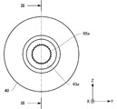
- FIG. 2 is a front view of an actuator viewed from the arrow AII in FIG. 1.
- FIG. 3 is a cross-sectional diagram of an actuator, sectioned on the section line III-III in FIG. 2.
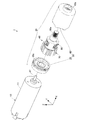
- FIG. 4 is an assembly perspective diagram of an actuator according to a first embodiment according to the present invention.
- FIG. 5 is a cross-sectional diagram of a second housing according to a first embodiment according to the present invention.
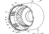
- FIG. 6 is a perspective diagram of a second housing according to a first embodiment according to the present invention.
- FIG. 7 is a perspective diagram of a first planetary gear mechanism according to a first embodiment according to the present invention.
- FIG. 1 is a perspective diagram of an actuator according to a first embodiment according to the present invention.
- FIG. 2 is a front view of an actuator viewed from the arrow AII in FIG. 1.
- FIG. 3 is a cross-sectional diagram
- FIG. 8 is a perspective diagram of a second planetary gear mechanism according to a first embodiment according to the present invention.
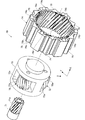
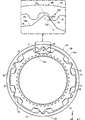
- FIG. 9 is a diagram for explaining the relationship between the second housing and the internal gear according to a first embodiment according to the present invention.
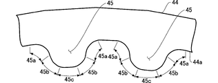
- FIG. 10 is an explanatory diagram focusing on a stopper that is formed in the second housing depicted in FIG. 9.
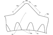
- FIG. 11 is an explanatory diagram focusing on a movement limiting raised portion that is formed on the inner gear depicted in FIG. 9.
- FIG. 12 is a diagram for explaining the state of contact with the second housing through rotation of the inner gear, depicted in FIG. 9, around the axis.
- FIG. 13 is a diagram for explaining the state of contact with the second housing through movement of the inner gear, depicted in FIG.
- FIG. 14 is a diagram for explaining the state of contact between the second housing and the inner gear, when viewed from the arrow XIV in FIG. 12.
- FIG. 15 is a schematic diagram comparing the movement limiting raised portion, depicted in FIG. 11, with another example of a movement limiting raised portion.
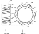
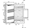
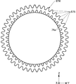
- FIG. 16 is a diagram depicting an inner gear according to a second embodiment according to the present invention.
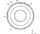
- FIG. 17 is a cross-sectional diagram of a second housing according to a second embodiment according to the present invention.
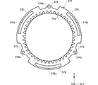
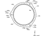
- FIG. 18 is a diagram depicting an inner gear according to a third embodiment according to the present invention.
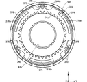
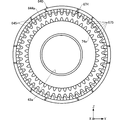
- FIG. 19 is a diagram depicting the state wherein the inner gear is housed in the second housing according to the third embodiment according to the present invention.
- FIG. 20 is a diagram depicting an inner gear according to a fourth embodiment according to the present invention.
- FIG. 21 is a diagram depicting the state wherein the inner gear is housed in the second housing according to the fourth embodiment according to the present invention.
- FIG. 22 is a diagram depicting an inner gear according to a fifth embodiment according to the present invention.
- FIG. 23 is a diagram depicting the state wherein the inner gear is housed in the second housing according to the fifth embodiment according to the present invention.
- FIG. 24 is an explanatory diagram focusing on the location of contact between the inner gear and the second housing according to the fifth embodiment according to the present invention.
- FIG. 25 is a diagram depicting an inner gear according to a sixth embodiment according to the present invention.
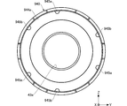
- FIG. 26 is a diagram depicting a second housing according to a sixth embodiment according to the present invention.
- FIG. 27 is a diagram depicting the state wherein the inner gear is housed in the second housing according to the sixth embodiment according to the present invention.
- FIG. 28 is a diagram depicting an inner gear according to a seventh embodiment according to the present invention.
- FIG. 29 is a diagram depicting a second housing according to the seventh embodiment according to the present invention.
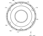
- FIG. 30 is a diagram depicting the state wherein the inner gear is housed in the second housing according to the seventh embodiment according to the present invention.
- FIG. 31 is a diagram depicting an inner gear according to an eighth embodiment according to the present invention.
- FIG. 32 is a diagram depicting a second housing according to the eighth embodiment according to the present invention.
- FIG. 33 is a diagram depicting the state wherein the inner gear is housed in the second housing according to the eighth embodiment according to the present invention.
- FIG. 34 is a diagram depicting an inner gear according to a ninth embodiment according to the present invention.
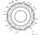
- FIG. 35 is a diagram depicting a second housing according to the ninth embodiment according to the present invention.
- FIG. 36 is a diagram depicting the state wherein the inner gear is housed in the second housing according to the ninth embodiment according to the present invention.
- the actuator 1 comprises, for example, a motor 10, and a planetary gear device 20 that is connected to the motor 10.
- the motor 10 has, for example, a motor main unit 11 and a rotary shaft 12, as illustrated in FIG. 3 and FIG. 4.
- the motor 10 rotates the rotary shaft 12, under the control of a controlling portion, not shown, to drive the planetary gear device 20.
- the planetary gear device 20 reduces, by a prescribed reduction ratio, the rotation that is inputted from the motor 10, directed in FIG. 1, and outputs it to an output gear 86a.
- the planetary gear device 20 comprises, for example, a housing 50, which has a first housing 30 and a second housing 40, and a planetary gear mechanism 60 that is contained within the housing 50, as depicted in FIG. 3 and FIG. 4.
- the first housing 30 is a member for, for example, attaching the motor 10 to the planetary gear device 20. Moreover, the first housing 30 is assembled together with the second housing 40 to form a containing space S, depicted in FIG. 5, for containing the planetary gear mechanism 60. As illustrated in FIG. 4, an opening 30a is formed in the center of the first housing 30, and the rotary shaft 12 of the motor 10 passes therethrough. The rotary shaft 12 that passes through the opening 30a is secured (connected) to a sun gear 71, described below, of the planetary gear mechanism 60.
- the first housing 30 is formed through injection molding, made from, for example, a synthetic resin.
- the second housing 40 is open on the side (the "one side") that is connected to the first housing 30, as illustrated in FIG. 5 and FIG. 6, for example, and the planetary gear mechanism 60, depicted in FIG. 4, can be contained therein from this open part.
- the planetary gear mechanism 60 as depicted in FIG. 4, for example, has a first planetary gear mechanism 70, a second planetary gear mechanism 80, and an output gear 86a, arranged along the axial direction.
- the planetary gear mechanism 60 reduces, in two stages, the (inputted) rotation produced by the motor 10, and outputs it from the output gear 86a.
- the second housing 40 as illustrated in FIG.
- the first position 41 of the second housing 40 has a round cylinder 44 and a stopper (second raised portion) 45 that extends along the axial direction (from one side in the axial direction toward the other side).
- the stopper 45 has a cross-section of a chevron shape when sectioned with a cross-section that is perpendicular to the axial direction, where the shape and size thereof are constant in the axial direction.
- the stopper 45 is formed in the range of a portion of the first position 41, in the axial direction, but may instead be formed across the entire range thereof.
- the stopper 45 as illustrated in FIG.
- each stopper 45 is disposed so as to form a pair, in the circumferential direction of the inner wall 44a of the round cylinder 44. Pairs of stoppers 45 are provided in six locations, with equal spacing, on the inner wall 44a of the round cylinder 44, for example.
- the cross-sectional shape of each stopper 45 as illustrated in FIG. 10, for example, has a standing portion 45a that forms an arc that gradually rises from the inner wall 44a of the round cylinder 44, a rounded apex 45c, and a connecting portion 45b, for connecting the standing portion 45a and the apex 45c while bulging. Note that the shape and size of the cross-section of the stopper 45 are constant in the axial direction. Because of this, as can be appreciated from FIG.
- the standing portion 45a, the connecting portion 45b, and the apex 45c are curved surfaces that have no curve in the direction that is parallel to the axis.
- the second position 42 of the second housing 40 has a round cylinder 46 and an inner tooth portion 47 that is formed on the inner wall of the round cylinder 46.
- the inner tooth portion 47 is at an incline, with an angle in respect to the axial direction, for example. That is, the second position 42 where the inner tooth portion 47 exists is structured as, for example, a helical gear.
- the third position 43 of the second housing 40 forms, for example, a cylinder, and has an opening 43a through which passes the output gear 86a of the planetary gear mechanism 60, depicted in FIG. 4.
- the torque outputted from the output gear 86a can be transmitted to an external mechanism thereby.
- the second housing 40 is formed through injection molding, made from, for example, a synthetic resin.
- the side of the second housing 40 that is open so as to attach to the first housing 30 is termed the "one side” (the -X direction side), and the side of the second housing 40 that has the opening 43a of the third position 43, which is the opposite side, is termed the "other side” (the +X direction side).
- the present invention is not limited thereto, and the side of the second housing 40 that has the opening 43a of the third position 43 may be read and interpreted as the one side, and the side of the second housing 40 that is open for attaching the first housing 30 may be read and interpreted as the other side.
- the planetary gear mechanism 60 as illustrated in FIG. 4, for example, is contained within the housing 50, and reduces the rotation transmitted from the motor 10 and outputs it from the output gear 86a.
- the planetary gear mechanism 60 has, for example, a first planetary gear mechanism 70 and a second planetary gear mechanism 80, disposed along the axial direction.
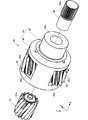
- the first planetary gear mechanism 70 as illustrated in FIG. 7, for example, comprises: a sun gear 71; three (a plurality of) planetary gears 72 that are disposed around the periphery centered on the sun gear 71; a carrier 73 for supporting rotatably the three (plurality of) planetary gears 72; and an inner gear 74. Note that while, for convenience in the perspective diagram in FIG. 7, only two planetary gears 72 are illustrated, another planetary gear 72 is provided at a position that is on the back side, hidden by the carrier 73.
- the sun gear 71 is an outer gear having sun tooth portions 71a formed on the outer peripheral surface thereof, and a rotary shaft 12 of the motor 10, depicted in FIG. 4, is secured (connected) thereto. Through this, the sun gear 71 is rotated by the operation of the motor 10.
- the sun tooth portions 71a have, for example, helical teeth that are cut at an angle in respect to the axis of the sun gear 71. That is, the sun gear 71 is, for example, a helical gear.
- the planetary gear 72 is, for example, an outer gear wherein planetary tooth portions 72a are formed on the outer peripheral surface thereof.
- the planetary tooth portions 72a have, for example, helical teeth that are cut at an angle in respect to the axis of the planetary gear 72. That is, the planetary gear 72 is, for example, a helical gear.
- Three planetary gears 72 are disposed at equal spacing on the same circle centered on the axis of the first planetary gear mechanism 70.
- the sun gear 71 is positioned between the three planetary gears 72, where the sun tooth portions 71a mesh with the respective planetary tooth portions 72a of the three planetary gears 72.
- the carrier 73 is formed in, for example, a cylindrical shape, where three containing openings 73a, for containing the planetary gears 72, are formed in the outer peripheral surface thereof.
- Each of the individual planetary gears 72 is supported rotatably, by a pin 76 that faces in the axial direction, within the respective containing opening 73a, as illustrated in FIG. 3.
- the planetary gears 72 are attached in a state wherein, for example, a portion of the planetary tooth portion 72a protrudes from the outer peripheral surface of the carrier 73. Through this, the planetary tooth portion 72a can mesh with the inner tooth portion 74a of the inner gear 74, described below.
- Inner tooth portions 74a are formed on the inner peripheral surface of the inner gear 74, as illustrated in, for example, FIG. 3 and FIG. 7.
- the inner tooth portion 74a is, for example, a helical gear having helical teeth that are cut at an angle in respect to the axis of the inner gear 74.
- the tooth tip rounding diameter for the inner gear 74 is greater than the diameter of the cylindrical carrier 73. Because of this, the carrier 73 that holds the planetary gear 72 is contained in the interior of the inner gear 74.
- the planetary tooth portions 72a that protrude from the outer peripheral surface of the carrier 73 are meshed with the inner tooth portions 74a of the inner gear 74.
- movement limiting raised portions (first raised portions) 75 which enter into the gap between the pairs of stoppers 45 that are formed on the inner wall 44a of the second housing 40, for example, are formed on the outer peripheral surface of the inner gear 74, as illustrated in FIG. 9.
- the movement limiting raised portions 75 are provided corresponding to, for example, the pairs of stoppers 45, formed in six locations, similar to the pairs of stoppers 45.
- the movement limiting raised portions 75 have cross-sections that are essentially triangular when sectioned with a plane that is perpendicular to the axial direction. The movement limiting raised portions 75, as depicted in FIG.
- slanted edge portions 75a that are straight, rising from the outer peripheral surface 74b of the inner gear 74, and rounded apexes 75b, positioned at locations wherein the slanted edge portions 75a, which arise from both sides, intersect.
- the cross-sectional shape and size of the movement limiting raised portion 75 is constant in the axial direction (with a constant extension from one side to the other side in the axial direction), and thus the slanted edge portion 75a of the movement limiting raised portion 75 structures a plane region.
- the movement limiting raised portions 75 are formed across the entire width of the inner gear 74, they may instead be formed in only a portion of the range thereof.
- a hemispherical protrusion 74b is formed on an end face, on the +X direction side of the inner gear 74.
- a hemispherical protrusion 74b is formed in each of the gaps between neighboring movement limiting raised portions 75, formed in a total of six locations.
- the form of contact between the protrusion 74b and the stepped surface 46a is that of a point contact, given that it is a contact between a spherical surface and a plane.
- the inner gear 74 is made from, for example, a synthetic resin. Note that, as described below, the inner gear 74 is formed from a synthetic resin of a hardness that is less than that of the synthetic resin from which the second housing 40, depicted in FIG. 9, is formed.
- the second housing 40 and the inner gear 74 are physically separate, and when the actuator 1 is not operating, a gap is formed therebetween. Because of this, the inner gear 74 is in a floating state within the second housing 40, allowing rotation around the axial direction, and movement in the direction that is perpendicular to the axial direction, within the second housing 40, in an amount commensurate with the gap that is provided between the inner gear 74 and the second housing 40. Additionally, through the movement limiting raised portion 75 that is formed on the inner gear 74 contacting the pair of stoppers 45, further movement of the inner gear 74 is prevented.
- the second planetary gear mechanism 80 which is another planetary gear mechanism, comprises, for example, a sun gear 81, three planetary gears 82, a carrier 83 that supports the three planetary gears 82 rotatably, and an output shaft 86, as depicted in FIG. 8. Note that while, for convenience in the perspective diagram in FIG. 8, only two planetary gears 82 are illustrated, another planetary gear 82 is provided at a position that is on the back side, hidden by the carrier 83.
- the sun gear 81 is an outer gear whereon sun tooth portions 81a are formed on the outer peripheral surface, for example, and is secured (connected), in a state wherein the axes are aligned together, to the carrier 73 of the first planetary gear mechanism 70, depicted in FIG. 7.
- the sun gear 81 will rotate identically to the rotation of the carrier 73 of the first planetary gear mechanism 70 (linked so as to be synchronized).
- the sun gear 81 accompanying rotation of the carrier 73 of the first planetary gear mechanism 70, rotates at the same rotational speed as the carrier 73 of the first planetary gear mechanism 70, in that the same rotational direction as the carrier 73 of the first planetary gear mechanism 70.
- the sun tooth portions 81a have, for example, helical teeth that are cut at an angle in respect to the axis of the sun gear 81. That is, the sun gear 81 is, for example, a helical gear.
- the planetary gear 82 is, for example, an outer gear wherein planetary tooth portions 82a are formed on the outer peripheral surface thereof.
- the planetary tooth portions 82a have, for example, helical teeth that are cut at an angle in respect to the axis of the planetary gear 82. That is, the planetary gear 82 is, for example, a helical gear.
- Three planetary gears 82 are disposed at equal spacing on the same circle centered on the axis of the second planetary gear mechanism 80.
- the sun gear 81 is positioned between the three planetary gears 82, where the sun tooth portions 81a mesh with the respective planetary tooth portions 82a of the three planetary gears 82. Additionally, the planetary gear 82 meshes with the inner tooth portions 47 that are formed on the second housing 40, depicted in FIG. 5 and FIG. 6.
- the carrier 83 has, for example, a gear retaining portion 84 for holding the planetary gears 82, and an output shaft retaining portion 85 for holding the output shaft 86.
- the gear retaining portion 84 is formed in, for example, a cylindrical shape, where three containing openings 84a, for containing the planetary gears 82, are formed in the outer peripheral surface thereof.
- Each of the individual planetary gears 82 is attached rotatably, by a pin 87 that faces in the axial direction, within the respective containing opening 84a, as illustrated in FIG. 3.
- the planetary gears 82 are attached in a state wherein a portion of the planetary tooth portion 82a protrudes from the outer peripheral surface of the carrier 83.
- the output shaft retaining portion 85 is formed as a cylinder with a diameter that is smaller than that of the gear retaining portion 84, and a fitting hole 85a, for holding the output shaft 86, is formed in the center portion of the output shaft retaining portion 85.
- the output shaft 86 is, for example, held on the carrier 83, and rotates together with the carrier 83.
- the output shaft 86 has an output gear 86a that has, on the shaft, teeth of a knurled shape. That is, the output shaft 86 structures, for example, a gear that has teeth of a knurled shape.
- the first direction in relation to the directions of rotation of each of the members, is the clockwise direction for the case when all of the members are viewed from the direction indicated by the arrow AII shown in FIG. 1.
- the second direction in relation to the directions of rotation of each of the members, is the counterclockwise direction for the case when all of the members are viewed from the direction indicated by the arrow AII shown in FIG. 2.
- the sun gear 71 When the rotary shaft 12 rotates in the first direction, the sun gear 71, depicted in FIG. 3 and FIG. 7, rotates in the first direction, accompanying the rotation of the rotary shaft 12.
- the three planetary gears 72 that mesh with the sun gear 71 each rotate in the second direction.
- the planetary gears 72 mesh with the inner gear 74, they rotate (revolve) in the first direction around the axis of the first planetary gear mechanism 70, through the rotation in the second direction.
- the carrier 73 rotates in the first direction, centered on its own axis.
- the sun gear 81 depicted in FIG. 3 and FIG. 8, which is secured by the carrier 73, will rotate in the first direction.
- the three planetary gears 82 that mesh with the sun gear 81 each rotate in the second direction.
- the planetary gears 82 mesh with the inner tooth portions 47, depicted in FIG. 5 and FIG. 6, they rotate (revolve) in the first direction around the axis of the second planetary gear mechanism 80, through the rotation in the second direction.
- the carrier 83 rotates in the first direction, centered on its own axis. Given this, the rotation of the carrier 83 is transmitted to the output shaft 86 that is held on the carrier 83.
- the second housing 40 and the inner gear 74 are physically separated. Additionally, when the actuator 1 is not operating, a gap is formed between the second housing 40 and the inner gear 74. Given this, when the actuator 1 operates, the inner gear 74 can rotate around the axis of the second housing 40, or move in a direction that is perpendicular to the axis, by an amount commensurate with the gap that is provided. For example, when the inner gear 74 is rotated in the first direction (clockwise) from the state shown in FIG. 9, each of the plurality of movement limiting raised portions 75, formed on the inner gear 74, will soon make linear contact with the corresponding stoppers 45 that are formed on the second housing 40, as depicted in FIG. 12.
- the inner gear 74 will be unable to rotate further in the clockwise direction. Because the stoppers 45 are formed in pairs, the rotation of the inner gear 74, around the axis, will be limited through the same linear contact even if the inner gear 74 were rotated in the second direction (the counterclockwise direction).
- the inner gear 74 moves, from the state depicted in FIG. 9, in a direction that is perpendicular to the axis, moving, for example, upward in the figure.
- the movement limiting raised portions 75 in the upper portion in the figure, formed on the inner gear 74 make linear contact with the pairs of stoppers 45 that are formed on the second housing 40.
- the inner gear 74 will be unable to move further in the upward direction, and the movement in the direction perpendicular to the axis will be limited.
- the apexes 75b of the inner gear 74 (more specifically, the apexes 75b of the movement limiting raised portions 75) will not contact the second housing 40 (or, more specifically, the inner wall 44a of the round cylinder 44).
- the limitation on the movement of the inner gear 74 in the directions perpendicular to the axis is not limited to upward movement of the inner gear 74. Because the six movement limiting raised portions 75 and pairs of stoppers 45 are arranged with equal spacing in the circumferential direction, they are able to limit movement of the inner gear 74 in a variety of directions, such as the vertical direction, crosswise direction, and diagonal direction in Fig. 9.
- FIG. 12 shows the state of linear contact between the inner gear 74 and the second housing 40 through rotation of the inner gear 74 around the axis.
- the pairs of stoppers 45 and the movement limiting raised portions 75 make contact in all six locations, and the forms of contact are the same for all. Because of this, a single contact location, wherein the contact is at the top in the figure, will be explained referencing the enlarged view in FIG. 12.
- the location of contact between the connecting portion 45b of the stopper 45, illustrated through a bulging convex curve, and the slanted edge portion 75a of the movement limiting raised portion 75, illustrated by a straight line, can be depicted as a contact point P1. That is, the contact will be in an extremely limited range.
- the cross-section of the second housing 40 and the cross-section of the inner gear 74 are of constant shapes and sizes in the axial direction. Because of this, the contact between the connecting portion 45b and the slanted edge portion 75a will be a contact between a convex curved surface that does not have a curve in the direction that is parallel to the axis, and a plane that is parallel to the axis. Because of this, the contact between the inner gear 74 and the second housing 40 will be linear contact, along the axial direction that is parallel to the X axis, as with the contact region 90 shown in FIG. 14.
- FIG. 13 shows the state of contact between the second housing 40 and the inner gear 74 through movement of the inner gear 74 in a direction that is perpendicular to the axis, for example, movement in the upward direction in the figure.
- the locations of contact between the second housing 40 and the inner gear 74 are the four locations indicated by the contact points P2 through P5.
- the contact points P2 and P3 are the locations of contact between the connecting portion 45b of the stopper 45, illustrated through a bulging convex curve, and the slanted edge portion 75a of the movement limiting raised portion 75, illustrated by a straight line.
- the contacts between the outer peripheral surfaces of the inner gear 74 and the inner peripheral surfaces of the second housing 40 can be caused to be linear contacts, even when the inner gear 74 has rotated around the axis, and even when it has moved in a direction perpendicular to the axis. Because the contact area between the outer peripheral surface of the inner gear 74 and the inner peripheral surface of the second housing 40, which, in this way, make linear contact, is small, the transmission to the second housing 40 of the vibration from the inner gear 74 during operation will be reduced. The vibration of the second housing 40 that is produced through transmission from the first planetary gear mechanism 70 is suppressed thereby, thus making it possible to suppress the noise that is produced from the planetary gear device 20 accompanying vibration caused by the first planetary gear mechanism 70.
- the "linear contact” described in the present specification is a state of contact wherein the contacting part forms a line, and does not indicate only a state of contact that would be illustrated by a single point or a plurality of points that are the contact points in each individual cross-section, but rather, as depicted in FIG. 14, a state of contact in a form wherein the width W is considered to be adequately small, when compared to the length L in the contact region 90 is included.
- the "linear contact” used in the present specification further includes a state of contact wherein the contact is discontinuous (contacting sporadically) so that the width W in the contact region 90 will form a line when an imaginary line is drawn along the axial direction.
- the "linear contact” used in the present specification further includes a state of contact wherein the width W in the contact region 90 forms a line that describes an angled line, rather than being in the axial direction.
- the "linear contact” used in the present specification further includes a state of contact wherein the contact is discontinuous (contacting sporadically) so that the width W in the contact region 90 will form a line when an imaginary line is drawn as an angled line, rather than along the axial direction.
- the present invention is not limited thereto, but rather the method of contact may be selected as appropriate depending on the form, and may be a form wherein there is point contact or a form wherein there is facial contact between the first raised portions and the second raised portions.
- a hemispherical protrusion 74b is formed on the end face of the inner gear 74 in the +X direction side, where the protrusion 74b contacts the stepped surface 46a of the second housing 40 (FIG. 5 and 6).
- the form of contact between the protrusion 74b and the stepped surface 46a can be kept to a contact in a limited range, that is, a point contact. This can reduce the transmission, to the second housing 40, of vibration from the inner gear 74 that is in operation.
- having the cross-section of the movement limiting raised portion 75 sectioned by a plane that is perpendicular to the axis, be a triangle, to structure with the apex 75b, which is narrow at the tip, facing outward, allows the inner gear 74 to be removed easily from the mold during injection molding. This can improve the yield.
- the movement limiting raised portions 75 are formed with straight slanted edge portions 75a on both sides in a cross-section that is sectioned by a plane that is perpendicular to the axial direction.
- FIG. 15 illustrates, as a reference example for a movement limiting raised portion 75, a movement limiting raised portion 100 of a shape wherein both sides are bulged, illustrated by the double dotted lines. Comparing the two, the cross-sectional area of the movement limiting raised portion 75 is smaller than the cross-sectional area of the movement limiting raised portion 100 by an amount commensurate with the area of the region indicated by the hatching.
- the present embodiment is able to reduce the load on the motor 10, and also reduce the manufacturing cost, by reducing the weight of the inner gear 74. Furthermore, because the of the reduction in weight of the inner gear 74 that will operate, the present invention can reduce (suppress) the impact when the inner gear 74 contacts the second housing 40, thus making it possible to reduce (suppress) the vibration of the second housing as well.
- the inner gear 74 is formed from a synthetic resin of a hardness that is less than that of the synthetic resin for forming the second housing 40.
- synthetic resins may be, for example, ultrapolymer polyethylene (UHPE), polyphenylene sulfide (PPS), polyarylate (PAR), polyacetal (POM), polyamide (PA), polycarbonate (PC), polybutylene terephthalate (PBT), polyether sulfone (PES), polyether ether ketone (PEEK), or the like.
- the synthetic resin for forming the inner gear 74 and the second housing 40 may be identical materials or may be different materials. They may be selected as appropriate in a range that produces the effects of the present invention.
- the synthetic resin that is relatively soft, suitable for forming the inner gear 74 preferably uses, for example, an ultrapolymer polyethylene (UHPE), polyphenylene sulfide (PPS), polyarylate (PAR), polyacetal (POM), or polyamide (PA).
- the relatively hard synthetic resin that is suitable for forming the second housing 40 uses, for example, polycarbonate (PC), polybutylene terephthalate (PBT), polyether sulfone (PES) polyphenylene sulfide (PPS), polyether ether ketone (PEEK), polyacetal (POM), or polyamide (PA).
- the synthetic resin for forming the second housing 40 will be harder, through changing, for example, the density of the synthetic resin.
- the present invention is able to reduce (suppress) the noise caused by vibration of the second housing 40, enabling also a further reduction (suppression) in the noise when the inner gear 74 collides with the second housing 40. It is thus possible to suppress the noise produced from the planetary gear device 20 accompanying vibration caused by the first planetary gear mechanism 70.
- the structure wherein the housing and the inner gear are separated is applied to only the first planetary gear mechanism that rotates at a high speed, and is not applied to the second stage planetary gear mechanism that rotates at a low speed. That is, in the present embodiment the structure wherein the inner gear is caused to float is used in the mechanism that rotates at a high speed, and which tends to produce large vibration and noise, where a housing structure wherein inner teeth are formed is used in the mechanism that rotates at a low speed, wherein the vibration and noise tends to be relatively less.
- the present embodiment not only suppresses the vibration and noise of the planetary gear device caused by the planetary gear mechanism, but also can prevent an increase in the number of components, beyond that which is necessary, in the planetary gear device, and prevent an increase in the assembly operations and assembly cost. Thus it is able to achieve a reduction in manufacturing cost of the planetary gear device.
- two mechanisms having different structures may be employed, as appropriate, depending on the form of rotation of the planetary gear mechanism, where the two mechanisms may be used in parallel.
- the directions of extension of the pairs of stoppers are formed on the second housing and the movement limiting raised portions that are formed on the inner gear are different from those in the first embodiment. Note that the other structures are identical to the structures in the first embodiment.
- six movement limiting raised portions 275 which extend diagonally in respect to the X axial direction, are formed with equal spacing on the outer peripheral surface of the inner gear 274.
- the cross-section of the movement limiting raised portion 275 when sectioned by a plane that is perpendicular to the direction of extension thereof (the direction that is inclined in respect to the X axial direction) is the same shape as the cross-section wherein the movement limiting raised portion 75 of the first embodiment (FIG. 7) was sectioned by a plane that is perpendicular to the direction of extension thereof (the X axial direction). That is, the movement limiting raised portion 275 has a triangular cross-section, as depicted in FIG. 11.
- the movement limiting raised portions 275 that are formed on the inner gear 274 are inserted between pairs of stoppers 245 that are formed at a first position 241 of a second housing 240 that is depicted in FIG. 17.
- the direction in which the pairs of stoppers 245 extend is the same as the direction of extension of the movement limiting raised portions 275 of the inner gear 274 that is contained in the second housing 240, a direction that is inclined in respect to the X axial direction.
- the cross-section of the pair of stoppers 245, when sectioned by a plane that is perpendicular to the direction of extension thereof (the direction that is inclined in respect to the X axial direction) is the same shape as the cross-section wherein the pair of stoppers 45 of the first embodiment (FIG. 6) was sectioned by a plane that is perpendicular to the direction of extension thereof (the X axial direction). That is, the pairs of stoppers 245 have cross sections of chevron shapes, as depicted in FIG. 10.
- the cross-sectional shapes of the movement limiting raised portions 275 and the cross-sectional shapes of the stoppers 245 are the same shapes as in the first embodiment, thus causing the form of contact between the two to be linear contact.
- the contact between the movement limiting raised portions 275 and the pairs of stoppers 245 will be linear contact along a direction that is inclined in respect to the X axial direction.
- the angle of the incline of the movement limiting raised portions 275 and the pairs of stoppers 245, in respect to the X axial direction which may be inclined to the same angle as the angle of the teeth in the case of the inner gear being a helical gear, for example, or may be inclined at an angle that is opposite of the angle of the teeth, or may be inclined to some different angle.
- the angle of inclination of the movement limiting raised portions 275 and of the pairs of stoppers 245 being the same as the angle of the helical gear of the inner gear can reduce the thrusting force that is produced within the planetary gear device.
- a third embodiment will be explained next in reference to FIG. 18 and FIG. 19.
- the number of pairs of stoppers formed on the second housing and the number of movement limiting raised portions formed on the inner gear is set to 3, reduced by half from the first embodiment wherein six of each were formed.
- three movement limiting raised portions 375 that extend in the X axial direction are formed, with equal spacing, on the outer peripheral surface of the inner gear 374.
- the cross sections of the movement limiting raised portions 375 are the same shapes as the cross sections of the movement limiting raised portions 75 in the first embodiment, having triangular cross-sectional shapes, as depicted in FIG. 11.
- Three arc portions 376 that structure the outer peripheral surface of the inner gear 374 are formed between the movement limiting raised portions 375.
- bow-shaped openings 376a On the insides of each of these three arc portions 376 are formed bow-shaped openings 376a that pass through the inner gear 374 in the X axial direction.
- These three arc portions 376 function as contacting portions for contacting the inner wall 344a of the second housing 340.
- three pairs of stoppers 345 are also formed with equal spacing on the inner wall 344a of the second housing 340, inserted between the movement limiting raised portions 375.
- the cross sections of the pairs of stoppers 345 are the same shapes as the cross sections of the pairs of stoppers 45 in the first embodiment, having chevron cross-sectional shapes, as depicted in FIG. 10. Note that when the inner gear 374 moves within the second housing 340, the movement limiting raised portions 375 and the pairs of stoppers 345 make linear contact, limiting the movement of the inner gear 374, where, additionally, the movement of the inner gear 374 is limited through the arc portions 376 of the inner gear 374 contacting the inner wall 344a of the second housing 340.
- the arc portions 376 and the inner wall 344a make facial contact.
- the formation of the openings 376a forms parts wherein vibrations do not propagate within the inner gear 374, and also reduce the rigidity of the arc portion 376.
- This makes it possible to reduce the propagation of vibration through the arc portions 376 to the second housing 340.
- This makes it possible to suppress the noise that is produced from the planetary gear device, through suppressing the transmission of vibration to the second housing 340, even when the inner gear 374 is in contact with the second housing 340 through the movement limiting raised portions 375, and even when it is in contact with the second housing 340 through the arc portions 376.
- protrusions may be provided protruding on the outside of the arc portions 376, to contact the inner wall 344a of the second housing 340 through the protrusions. This makes it possible to limit, into a narrow range, the range of contact between the arc portions 376 and the second housing 340.
- a fourth embodiment will be explained next in reference to FIG. 20 and FIG. 21.
- three movement limiting raised portions 475 that extend in the X axial direction are formed, with equal spacing, on the outer peripheral surface of the inner gear 474.
- the movement limiting raised portion 475 has a triangular cross-section that has an apex 475b and slanted edge portions 475a formed on both sides of the apex 475b.
- Three arc portions 476 that structure the outer peripheral surface of the inner gear 474 are formed between the movement limiting raised portions 475. These three arc portions 476 are formed in a state further pulled in toward the axis side (the inside) than with the arc portions 376 of the third embodiment, depicted in FIG. 19.
- three pairs of stoppers 445 are also formed with equal spacing on the inner wall 444a of the second housing 440, inserted between the movement limiting raised portions 475.
- the cross sections of the pairs of stoppers 445 are the same shapes as the cross sections of the pairs of stoppers 45 in the first embodiment, having chevron cross-sectional shapes, as depicted in FIG. 10. Note that when the inner gear 474 moves within the second housing 440, the movement limiting raised portions 475 and the pairs of stoppers 445 make linear contact, limiting the movement of the inner gear 474.
- the arc portions 476 are formed in a state that is pulled in toward the axis side (inside), as described above, and thus do not make contact with the inner wall 444a of the second housing 440.
- the number of locations wherein there is contact between the movement limiting raised portions 475 and the pairs of stoppers 445 is reduced to 3 locations, and linear contact is made between the two, making it possible to reduce the area of contact when compared to the forms described above, reducing the transmission of vibration from the inner gear 474 that is operating to the second housing 440.
- a fifth embodiment will be explained next in reference to FIG. 22 through FIG. 24.
- three movement limiting raised portions 575 that extend in the X axial direction are formed, with equal spacing, on the outer peripheral surface of the inner gear 574.
- the movement limiting raised portion 575 has a chevron shape that bulges outward.
- Three arc portions 576 that structure the outer peripheral surface of the inner gear 574 are formed between the movement limiting raised portions 575. These three arc portions 576 are formed in a state pulled in toward the axis side (the inside) in the same way as with the arc portions 476 of the fourth embodiment, depicted in FIG. 21.
- three pairs of stoppers 545 are also formed with equal spacing on the inner wall 544a of the second housing 540, inserted between the movement limiting raised portions 575.
- the cross sections of the pairs of stoppers 545 are the same shapes as the cross sections of the pairs of stoppers 45 in the first embodiment, having chevron cross-sectional shapes, as depicted in FIG. 10. Note that when the inner gear 574 moves within the second housing 540, the movement limiting raised portions 575 and the pairs of stoppers 545 make contact, limiting the movement of the inner gear 574.
- each of the movement limiting raised portions 575 that have the chevron cross-sectional shapes and the pairs of stoppers for 545 will be explained in reference to FIG. 24.
- the inner gear 574 when the actuator is not operating, is indicated by the solid line.
- the inner gear 574 depicted by the double dotted line, is in the state wherein it has moved upward, through the operation of the actuator, to contact the second housing 540.
- the contact between the pair of stoppers 545 and the movement limiting raised portions 575 is contact between convex curved surfaces, so will be linear contact at the contact points P6 and P7 between the pairs of stoppers 545 and the movement limiting raised portions 575.
- the arc portions 576 are formed in a state that is pulled in toward the axis side (inside), as described above, and thus do not make contact with the inner wall 544a of the second housing 540.
- FIG. 25 A sixth embodiment will be explained next in reference to FIG. 25 through FIG. 27.
- a plurality of movement limiting raised portions 675 structured from external teeth that are cut along the X axial direction is formed with equal spacing on the outer peripheral surface of the inner gear 674.
- the movement limiting raised portions 675 have a cross-sectional shape that is essentially trapezoidal.
- a plurality of stoppers 645 that are inserted between the movement limiting raised portions 675 are structured from inner teeth that are cut along the X axial direction on the inner wall 644a of the second housing 640.
- the stoppers 645 have a cross-sectional shape that is essentially trapezoidal.
- the inner gear 674 is contained within the second housing 640, and when the inner gear 674 moves from this state, the plurality of movement limiting raised portions 675 contact the plurality of stoppers 645. The movement of the inner gear 674 is limited thereby. Note that the movement limiting raised portions 675 and stoppers 645 are formed in more locations when compared to the forms described above.
- each individual contact location is limited to a narrow range. Because of this, the propagation to the second housing 640 of the vibrations from the inner gear 674 during operation is reduced. This suppresses the vibration of the second housing 640, which can suppress the noise that is produced from the planetary gear device.
- outer teeth that are formed on the outer peripheral surface of the inner gear 674 are not limited to outer teeth that are cut along the X axial direction, but rather may be outer teeth that are cut along a direction that is inclined in respect to the X axial direction.
- the inner teeth that are formed on the inner wall 644a of the second housing 640 are not limited to inner teeth that are cut along the X axial direction, but rather may be inner teeth that are cut along a direction that is inclined in respect to the X axial direction.
- the outer teeth that are formed on the outer peripheral surface of the inner gear 674 and the inner teeth that are formed on the inner wall 644a of the second housing 640 are cut along a direction that is inclined in respect to the X axial direction, there is no particular limitation on the angle thereof, and, for example, if the inner gear is a helical gear, the incline may be at an angle that is the same as the angle of the teeth, or may be an incline at an angle that is opposite of the angle of the teeth, or may be inclined at some different angle.
- angle of the outer teeth that are formed on the outer peripheral surface of the inner gear 674 and of the inner teeth that are formed on the inner wall 644a of the second housing 640 is the same as the angle of the helical gear of the inner gear, this can reduce the amount of thrust produced within the planetary gear device.
- a seventh embodiment will be explained next in reference to FIG. 28 through FIG. 30.
- the locations wherein the pairs of stoppers and the movement limiting raised portions are provided are switched, where the movement limiting raised portions are provided on the inner peripheral surface of the second housing and the pairs of stoppers are provided on the outer peripheral surface of the inner gear.
- stoppers 745 that extend in the X axial direction are formed, with equal spacing, on the outer peripheral surface of the inner gear 774.
- the cross sections of the pairs of stoppers 745 are the same shapes as the cross sections of the pairs of stoppers 45 in the first embodiment, having chevron cross-sectional shapes, as depicted in FIG. 10. Movement limiting raised portions 775, formed on the second housing 740, depicted in FIG. 29, are inserted between the pairs of stoppers 745.
- movement limiting raised portions 775 that extend in the X axial direction are formed, with equal spacing, on the second housing 740.
- the cross sections of the movement limiting raised portions 775 are the same shapes as the cross sections of the movement limiting raised portions 75 in the first embodiment, having triangular cross-sectional shapes, as depicted in FIG. 11.
- the inner gear 774 is contained within the second housing 740, and when the inner gear 774 moves from this state, the plurality of movement limiting raised portions 775 contact the pairs of stoppers 745, constraining the movement of the inner gear 774.
- the contact between the movement limiting raised portions 775 and the pairs of stoppers 745 can be linear contact, the same as the form of contact in the first embodiment. Because of this, the propagation to the second housing 740 of the vibrations from the inner gear 774 during operation is reduced. This suppresses the vibration of the second housing 740, which can suppress the noise that is produced from the planetary gear device.
- the spacing with which the pairs of stoppers and the movement limiting raised portions are laid out is with unequal spacing rather than with equal spacing.
- three movement limiting raised portions 875 that extend in the X axial direction are formed on the outer peripheral surface of the inner gear 874.
- the movement limiting raised portions 875 are arranged with unequal spacing.
- the cross sections of the movement limiting raised portions 875 are the same shapes as the cross sections of the movement limiting raised portions 75 in the first embodiment, having triangular cross-sectional shapes, as depicted in FIG. 11.
- three pairs of stoppers 845 are also formed with unequal spacing on the inner wall 844a of the second housing 840, inserted between the movement limiting raised portions 875.
- the cross sections of the pairs of stoppers 845 are the same shapes as the cross sections of the pairs of stoppers 45 in the first embodiment, having chevron cross-sectional shapes, as depicted in FIG. 10.
- the inner gear 874 is contained within the second housing 840, and when the inner gear 874 moves from this state, the plurality of movement limiting raised portions 875 contact the pairs of stoppers 845, constraining the movement of the inner gear 874.
- the contact between the movement limiting raised portions 875 and the pairs of stoppers 845 can be linear contact, the same as the form of contact in the first embodiment. Because of this, the propagation to the second housing 840 of the vibrations from the inner gear 874 during operation is reduced. This suppresses the vibration of the second housing 840, which can suppress the noise that is produced from the planetary gear device.
- arc portions 376 depicted in FIG. 18 may be formed at locations wherein there are spaces through the arrangement, with unequal spacing, of the movement limiting raised portions 875 and the pairs of stoppers 845. This makes it possible to limit the movement of the inner gear 874 while suppressing transmission of vibration from the inner gear 874.
- a ninth embodiment will be explained next in reference to FIG. 34 through FIG. 36.
- the stoppers that contact the movement limited raised portions are laid out with a one-to-one relationship with the movement limited raised portions, rather than being laid out in pairs.
- movement limiting raised portions 975 that extend in the X axial direction are formed, with equal spacing, on the outer peripheral surface of the inner gear 974.
- the cross sections of the movement limiting raised portions 975 are the same shapes as the cross sections of the movement limiting raised portions 75 in the first embodiment, having triangular cross-sectional shapes, as depicted in FIG. 11.
- first stoppers 945a are formed with equal spacing
- second stoppers 945b are formed with equal spacing, on the inner wall 344a of the second housing 340.
- the positions wherein the first stoppers 945a are arranged and the positions wherein the second stoppers 945b are arranged are shifted from each other in the circumferential direction.
- the cross sections of the first stoppers 945a and the cross sections of the second stoppers 945b are the same shapes as the cross sections of the pairs of stoppers 45 in the first embodiment, having chevron cross-sectional shapes, as depicted in FIG. 10.
- the first stopper 945a is disposed on one of the two sides of the nearest movement limiting raised portion 975.
- a second stoppers 945b is disposed on the other of the two sides of the nearest movement limiting raised portion 975.
- the "one side” is the left side of the movement limiting raised portion 975 in the figure, the side wherein the first stopper 945a is disposed.
- the "other side” is the right side in the figure of the movement limiting raised portion 975 that protrudes upward.
- the movement limiting raised portion 975 makes contact with the first stopper 945a, limiting the rotation of the inner gear 974. Additionally, when the inner gear 974 rotates in the clockwise direction in the figure (the first direction), the movement limiting raised portion 975 makes contact with the second stopper 945b, limiting the rotation of the inner gear 974. Moreover, when the inner gear 974 moves in the radial direction, the movement limiting raised portion 975 makes contact with the first stopper 945a and the second stopper 945b, limiting the movement of the inner gear 974.
- the contact of limiting raised portion 975 with the first stopper 945a and the second stopper 945b in this way can be linear contact, the same as the form of contact in the first embodiment. Because of this, the propagation to the second housing 940 of the vibrations from the inner gear 974 during operation is reduced. This suppresses the vibration of the second housing 940, which can suppress the noise that is produced from the planetary gear device.
- the present invention is not limited to the embodiments described above, but rather a variety of modifications and applications are possible. While in the embodiments set forth above, the cross sections of the pairs of stoppers 45 were chevron shapes and the cross sections of the movement limiting raised portions 75 were triangular, instead the cross-sectional shapes may be switched, with the cross sections of the pairs of stoppers being triangular and the cross sections of the movement limited raised portions that are inserted between the stoppers being chevron shapes.
- arc portions 376 depicted in FIG. 18, may be provided so as to complement the functioning thereof. This makes it possible to stabilize the orientation of the inner gear during operation, making it possible to suppress the noise that is produced from the planetary gear device.
- linear contact may be achieved through the second housing 40 having locally concave parts with large curvature, the inner gear 74 having convex curved surfaces with less curvature, where the concave curved surfaces with high curvature contact the convex curved surfaces that are bulging.
- the actual structure for achieving linear contact is arbitrary.
- the configuration of the inner gear in the location that makes linear contact may be swapped with the configuration of the second housing.
- the actuator 1 was provided with a two-stage planetary gear mechanism of a first planetary gear mechanism 70 and a second planetary gear mechanism 80, as the reduction mechanism for reducing the rotation of the motor 10, the number of stages can be set arbitrarily.
- the reduction ratio may be increased through providing three or more stages of planetary gear mechanisms, or the structure may include only a single-stage planetary gear mechanism.
- a configuration was used wherein the structure wherein the housing and the inner gear were separate was applied only to the first planetary gear mechanism 70, which is the first-stage mechanism that rotates at a high speed, and a housing that was formed with inner teeth on the inner peripheral surface thereof was used in the second planetary gear mechanism 80, which is the second-stage mechanism that rotates at a low speed.
- a structure wherein the housing and the inner gear are separated may be used also in the second planetary gear mechanism 80 that is the second-stage mechanism, to achieve a reduction in vibration and noise.
- the explanation was for a case wherein a reduction gear was used for reducing the rotation of the motor 10 and outputting it from an output gear 86a
- the part that is provided with the output shaft 86, depicted in FIG. 8 may be used as the input side and connected to the rotary shaft of a motor
- the part that is provided with the sun gear 71, depicted in FIG. 7 may be used as the output side, and connected to the output shaft. This would increase and output the rotation of the motor, to be used as an increasing the mechanism.
- the structure wherein the inner gear and the housing are separated is employed due to the higher-speed operation of the first planetary gear mechanism 70 that is shown in FIG. 7. Moreover, because the rotation of the motor is transmitted directly to the second planetary gear mechanism 80 that is depicted in FIG. 8, preferably the structure wherein the inner gear and the housing are separated is employed, as necessary. Moreover, the present invention may also be applied to industrial equipment such as robots and machine tools, and to playground equipment such as so-called "teacups.”
- the separate structural units for the inner gear and the housing are applied to the planetary gear mechanism that operates at the highest speed, when planetary gear mechanisms are provided in three or more stages. This can reduce effectively the vibration and noise that is produced. Moreover, because there is little vibration and noise produced by the planetary gear mechanism that operates at the lowest speed, a structure is applied that is equipped with a housing where inner teeth are formed on the inner peripheral surface. This eliminates the need for the separate structures, more than necessary, for the inner gear and the housing, making it possible to avoid increases in the number of components and increases in the assembly operation and assembly costs, thus making it possible to suppress production costs.
- the planetary gear mechanism of the planetary gear device was achieved through three planetary gears; however, the present invention is not limited thereto.
- the planetary gear device may be achieved through the use of a planetary gear mechanism that uses, for example, a single planetary gear or a plurality, other than three, of planetary gears.
- the planetary gear device to which the present invention is applied may be applied to a variety of machines and apparatuses that use reducing mechanisms or increasing mechanisms, such as automobiles, robots, industrial equipment, playground equipment, or the like.
- the structure may be one wherein the movement is limited within the housing through point contact between the movement limiting raised portions (first raised portions) and the pairs of stoppers (second raised portions). More specifically, the pairs of stoppers in FIG. 5 (second raised portions) 45 may be of a shape that is discontinuous in the axial direction (with a plurality of gaps), and the movement limiting raised portions (first raised portions) 75 in FIG. 7 may be of a shape that is discontinuous in the axial direction (with a plurality of gaps).
- the present invention can have a variety of embodiments or modifications that do not deviate from the scope of the spirit of the broad definition of the present invention. Moreover, the embodiments set forth above are to explain this invention, and do not limit the scope of the present invention. That is, the scope of the present invention is defined by the claims, not the embodiments. Given this, various modifications that are within the patent claims, or within the scope of the broad meaning of the inventions that are equivalent thereto, are viewed as being within the scope of the invention.
- Actuator 10 Motor 11: Motor Main Unit 12: Rotary Shaft 20: Planetary Gear Device 30: First Housing 30a: Opening 40: Second Housing 41: First Position 42: Second Position 43: Third Position 43a: Opening 44: Round Cylinder 44a: Inner Wall 45: Stopper (Second Raised Portion) 45a: Standing Portion 45b: Connecting Portion 45c: Apex 46: Round Cylinder 47: Inner Tooth Portion 50: Housing 60: Planetary Gear Mechanism 70: First Planetary Gear Mechanism 71: Sun Gear 71a: Sun Tooth Portion 72: Planetary Gear 72a: Planetary Tooth Portion 73: Carrier 73a: Containing Opening 74: Inner Gear 74a: Inner Tooth Portion 74b: Outer Peripheral Surface 75: Movement Limiting Raised Portion (First Raised Portion) 75a: Slanted Edge Portion 75b: Apex 75c: Notched Portion 76: Pin 80: Second Planetary Gear Mechanism 81: Sun Gear 81a: Sun Tooth Portion 82
Landscapes
- Engineering & Computer Science (AREA)
- General Engineering & Computer Science (AREA)
- Mechanical Engineering (AREA)
- Physics & Mathematics (AREA)
- Electromagnetism (AREA)
- Thermal Sciences (AREA)
- Retarders (AREA)
- General Details Of Gearings (AREA)
Abstract
[Technical Problem] To provide separate structural units for an inner gear and a housing, that suppress vibration transmitted from a planetary gear mechanism and suppress noise produced by the planetary gear device. [Solution to Problem] Separate structural units for an inner gear and a housing comprising: an inner gear wherein a first raised portion that extend towards a direction that is inclined in respect to the axial direction is formed on the outer peripheral surface; and a housing wherein a second raised portion that extends in a direction that is inclined in respect to the axial direction is formed on the inner peripheral surface, and that contains the inner gear in a state wherein there is a gap from the inner peripheral surface. The movement of the inner gear within the interior of the housing is limited through linear contact of the first raised portion and the second raised portion.
Description
The present invention relates to separate structural units for an inner gear and a housing, a planetary gear device comprising said separate structural units, and an actuator comprising said planetary gear device.
Planetary gear devices are used in a variety of technologies, such as automobiles, robots, and the like. Because planetary gear devices are structured through a combination of a plurality of gears, noise and vibration is produced during operation. Technologies have been proposed to suppress the production of noise and vibration when the planetary gear device is operating.
As one of such technologies that has been proposed, Patent Document 1 discloses a planetary gear device with a structure that separates the inner gear and the housing, with a gap between the two. Using a structure wherein the inner gear and the housing are separate makes transmission of vibrations from the inner gear to the housing more difficult, reducing the noise that is produced from the vibrations.
[Patent Document 1] Japanese Unexamined Patent Application Publication H06-074835
In the planetary gear device of Patent Document 1, the outer peripheral surface of the inner gear and the inner peripheral surface of the housing are formed with shapes that fit together. Because of this, when the inner gear moves during operation of the planetary gear device, there is contact between the outer peripheral surface of the inner gear and the inner peripheral surface of the housing, in a range that has some degree of width. Through this, in the state wherein there is contact between the inner gear and the housing, the vibration of the planetary gear mechanism that propagates to the inner gear is readily transmitted to the housing, so there is a problem in that there is a tendency for the planetary gear device to also produce noise.
The present invention is to solve problem areas such as described above, and the object is to provide separate structural units for the inner gear and the housing, able to suppress transmission of the vibrations from the planetary gear mechanism and noise that is produced by the planetary gear device, and to provide a planetary gear device equipped with the separate structural units, and an actuator equipped with the planetary gear device.
Separate structural units for an inner gear and a housing according to the present invention comprise: an inner gear having a first raised portion, that extends from one side in the axial direction to the other side in the axial direction, formed on the outer peripheral surface thereof, in a direction that is inclined in respect to the axial direction; and a housing, wherein a second raised portion that extends in a direction that is inclined in respect to the axial direction is formed on the inner peripheral surface thereof, for containing the inner gear in a state wherein a gap is provided from the inner peripheral surface, wherein: the movement of the inner gear within the interior of the housing is limited through linear contact between the first raised portion and the second raised portion.
In another aspect of the present invention, separate structural units for an inner gear and a housing comprise: an inner gear with a plurality of first raised portions and a contacting portion that is located between adjacent first raised portions, formed on the outer peripheral surface thereof; and a housing wherein a second raised portion is formed on the inner peripheral surface thereof, for containing the inner gear in a state wherein a gap is provided from the inner peripheral surface, wherein: movement of the inner gear within the housing is limited through contact of the first raised portion and the second raised portion, and movement within the housing is limited through contact of the contacting portion and the inner peripheral surface of the housing; and an opening that is provided in the axial direction is formed on the inside of the contacting portion of the inner gear.
In another aspect of the present invention, separate structural units for an inner gear and a housing comprise: an inner gear wherein a plurality of first raised portions that extend in a prescribed direction is formed on the outer peripheral surface; and a housing wherein a plurality of second raised portions, which extend in the prescribed direction, is formed on the inner peripheral surface thereof, for containing the inner gear in a state wherein a gap is provided from the inner peripheral surface, wherein: the movement of the inner gear within the housing is limited through linear contact of the first raised portion with the corresponding second raised portion; and the plurality of first raised portions and the plurality of second raised portions are disposed with each equally spaced.
In another aspect of the present invention, separate structural units for an inner gear and a housing comprise: an inner gear wherein a plurality of first raised portions that extend in a prescribed direction is formed on the outer peripheral surface; and a housing wherein a plurality of second raised portions, which extend in the prescribed direction, is formed on the inner peripheral surface thereof, for containing the inner gear in a state wherein a gap is provided from the inner peripheral surface, wherein: the movement of the inner gear within the housing is limited through linear contact of the first raised portion with the corresponding second raised portion; and the plurality of first raised portions and the plurality of second raised portions are disposed with each adjacent raised portion unequally spaced.
Of the first raised portion and the second raised portion, one raised portion may be formed in a pair with a space therebetween, and the other raised portion may be disposed so as to be inserted between the one raised portion that is formed in a pair; and of the location of contact of the one raised portion and the location of contact of the other raised portion, which contact each other, at least one may be a curved surface.
The one raised portion may be the second raised portion and the other raised portion may be the first raised portion; and the first raised portion may have a cross-section that is triangular when sectioned by a plane that is perpendicular to the axial direction, and may contact the second raised portion at an inclined surface that is formed in a plane.
The one raised portion may be the first raised portion and the other raised portion may be the second raised portion; and the second raised portion may have a cross-section that is triangular when sectioned by a plane that is perpendicular to the axial direction, and may contact the first raised portion at an inclined surface that is formed in a plane.
Of the location of contact of the first raised portion and the location of contact of the second raised portion, which contact each other, one may be a convex curved surface and the other may be a plane.
The location of contact of the first raised portion and the location of contact of the second raised portion, which contact each other, may be convex curved surfaces.
Of the location of contact of the first raised portion and the location of contact of the second raised portion, which contact each other, one may be a convex curved surface and the other may be a concave curved surface.
The first raised portion may be structured from an outer tooth that is cut along the axial direction or an outer tooth that is cut along a direction that is inclined in respect to the axial direction, on the outer peripheral surface of the inner gear; and the second raised portion may be structured from an inner tooth that is cut along the axial direction or an inner tooth that is cut along a direction that is inclined in respect to the axial direction, on the inner peripheral surface of the housing.
One corresponding second raised portion may be provided for each of the plurality of first raised portions, where of the plurality of second raised portions, a portion may contact the corresponding first raised portion when the inner gear is rotated in a first direction, and the remaining portion may contact the corresponding first raised portion when the inner gear is rotated in a second direction.
The inner gear and the housing may be made from a synthetic resin; and the inner gear may be formed from a synthetic resin of a hardness that is less than that of the synthetic resin for forming the housing.
A planetary gear device according to the present invention comprises: separate structural units for an inner gear and a housing as set forth above; one or more planetary gears that mesh with the inner gear; a sun gear that meshes with the one or more planetary gears, positioned at the center of the one or more planetary gears; and a carrier that supports the one or more planetary gears rotatably.
The structure may further comprise a second sun gear that rotates similarly to the rotation of the carrier accompanying rotation of the carrier; one or more second planetary gears that are disposed on the periphery of the second sun gear, and that mesh with the second sun gear; a second carrier that supports one or more second planetary gears rotatably; and a second housing whereon is formed, on the inner peripheral surface thereof, inner teeth that mesh with the one or more second planetary gears, wherein: the housing and the second housing may be formed integrally.
In another aspect of the present invention, a planetary gear device comprises at least two stages of planetary gear mechanisms that each comprises: a sun gear; one or more planetary gears, arranged on the periphery of the sun gear, for meshing with the sun gear; and a carrier that supports the one or more planetary gears rotatably, wherein: of the at least two stages of planetary gear mechanisms, the planetary gear mechanism that operates at the highest speed comprises separate structural units for an inner gear and a housing as set forth above, where the one or more planetary gears of the planetary gear mechanism and the inner gear mesh; and of the at least two stages of the planetary gear mechanism, the planetary gear mechanism that operates at the lowest speed comprises a housing wherein inner teeth that mesh with the one or more planetary gears of the planetary gear mechanism are formed on the inner peripheral surface.
An actuator according the present invention comprises: a planetary gear device as set forth above; and a motor, connected to the planetary gear device, for driving the planetary gear device.
In the present invention, the range of contact between the inner gear and the housing is narrower than in the prior art, thus reducing the transmission, to the housing, of vibrations caused by the planetary gear mechanism. This can suppress the transmission of vibrations from the planetary gear mechanism, and can suppress the noise that is produced from the planetary gear device accompanying vibration of the planetary gear mechanism.
Separate structural units for an inner gear and a housing, a planetary gear device, and an actuator according to an ideal embodiment according to the present invention will be explained below in reference to the drawings. Note that for ease in understanding the drawings, in each of the drawings an orthogonal coordinate system is depicted with an X axis that is parallel to the axial direction of the actuator 1 according to the embodiment according to the present invention, and a Y axis and a Z axis that are perpendicular to the X axis.
(Structure of the Actuator 1)
As illustrated in FIG. 1 and FIG. 2, the actuator 1 comprises, for example, amotor 10, and a planetary gear device 20 that is connected to the motor 10.
As illustrated in FIG. 1 and FIG. 2, the actuator 1 comprises, for example, a
The motor 10 has, for example, a motor main unit 11 and a rotary shaft 12, as illustrated in FIG. 3 and FIG. 4. The motor 10 rotates the rotary shaft 12, under the control of a controlling portion, not shown, to drive the planetary gear device 20.
The planetary gear device 20 reduces, by a prescribed reduction ratio, the rotation that is inputted from the motor 10, directed in FIG. 1, and outputs it to an output gear 86a. The planetary gear device 20 comprises, for example, a housing 50, which has a first housing 30 and a second housing 40, and a planetary gear mechanism 60 that is contained within the housing 50, as depicted in FIG. 3 and FIG. 4.
The first housing 30 is a member for, for example, attaching the motor 10 to the planetary gear device 20. Moreover, the first housing 30 is assembled together with the second housing 40 to form a containing space S, depicted in FIG. 5, for containing the planetary gear mechanism 60. As illustrated in FIG. 4, an opening 30a is formed in the center of the first housing 30, and the rotary shaft 12 of the motor 10 passes therethrough. The rotary shaft 12 that passes through the opening 30a is secured (connected) to a sun gear 71, described below, of the planetary gear mechanism 60. The first housing 30 is formed through injection molding, made from, for example, a synthetic resin.
The second housing 40 is open on the side (the "one side") that is connected to the first housing 30, as illustrated in FIG. 5 and FIG. 6, for example, and the planetary gear mechanism 60, depicted in FIG. 4, can be contained therein from this open part. The planetary gear mechanism 60, as depicted in FIG. 4, for example, has a first planetary gear mechanism 70, a second planetary gear mechanism 80, and an output gear 86a, arranged along the axial direction. The planetary gear mechanism 60 reduces, in two stages, the (inputted) rotation produced by the motor 10, and outputs it from the output gear 86a. The second housing 40, as illustrated in FIG. 5, for example, has a first position 41 wherein the first planetary gear mechanism 70 is contained, a second position 42 wherein the second planetary gear mechanism 80 is contained, and a third position 43 wherein the output gear 86a of the second planetary gear mechanism 80 protrudes to the outside.
The first position 41 of the second housing 40, as depicted in FIG. 5 and FIG. 6, for example, has a round cylinder 44 and a stopper (second raised portion) 45 that extends along the axial direction (from one side in the axial direction toward the other side). The stopper 45 has a cross-section of a chevron shape when sectioned with a cross-section that is perpendicular to the axial direction, where the shape and size thereof are constant in the axial direction. The stopper 45 is formed in the range of a portion of the first position 41, in the axial direction, but may instead be formed across the entire range thereof. The stopper 45, as illustrated in FIG. 9, for example, is disposed so as to form a pair, in the circumferential direction of the inner wall 44a of the round cylinder 44. Pairs of stoppers 45 are provided in six locations, with equal spacing, on the inner wall 44a of the round cylinder 44, for example. The cross-sectional shape of each stopper 45, as illustrated in FIG. 10, for example, has a standing portion 45a that forms an arc that gradually rises from the inner wall 44a of the round cylinder 44, a rounded apex 45c, and a connecting portion 45b, for connecting the standing portion 45a and the apex 45c while bulging. Note that the shape and size of the cross-section of the stopper 45 are constant in the axial direction. Because of this, as can be appreciated from FIG. 6, for example, the standing portion 45a, the connecting portion 45b, and the apex 45c are curved surfaces that have no curve in the direction that is parallel to the axis. A movement limiting raised portion 75 of the inner gear 74, depicted in FIG. 9 and described below, is inserted between the pair of stoppers 45, to limit the movement of the inner gear 74 within the second housing 40.
The second position 42 of the second housing 40, as illustrated in FIG. 5 and FIG. 6, for example, has a round cylinder 46 and an inner tooth portion 47 that is formed on the inner wall of the round cylinder 46. The inner tooth portion 47 is at an incline, with an angle in respect to the axial direction, for example. That is, the second position 42 where the inner tooth portion 47 exists is structured as, for example, a helical gear.
The third position 43 of the second housing 40 forms, for example, a cylinder, and has an opening 43a through which passes the output gear 86a of the planetary gear mechanism 60, depicted in FIG. 4. The torque outputted from the output gear 86a can be transmitted to an external mechanism thereby. The second housing 40 is formed through injection molding, made from, for example, a synthetic resin.
Additionally, for convenience in the present specification, in FIG. 4 through FIG. 6 the side of the second housing 40 that is open so as to attach to the first housing 30 is termed the "one side" (the -X direction side), and the side of the second housing 40 that has the opening 43a of the third position 43, which is the opposite side, is termed the "other side" (the +X direction side). However, the present invention is not limited thereto, and the side of the second housing 40 that has the opening 43a of the third position 43 may be read and interpreted as the one side, and the side of the second housing 40 that is open for attaching the first housing 30 may be read and interpreted as the other side.
The planetary gear mechanism 60, as illustrated in FIG. 4, for example, is contained within the housing 50, and reduces the rotation transmitted from the motor 10 and outputs it from the output gear 86a. The planetary gear mechanism 60 has, for example, a first planetary gear mechanism 70 and a second planetary gear mechanism 80, disposed along the axial direction.
The first planetary gear mechanism 70, as illustrated in FIG. 7, for example, comprises: a sun gear 71; three (a plurality of) planetary gears 72 that are disposed around the periphery centered on the sun gear 71; a carrier 73 for supporting rotatably the three (plurality of) planetary gears 72; and an inner gear 74. Note that while, for convenience in the perspective diagram in FIG. 7, only two planetary gears 72 are illustrated, another planetary gear 72 is provided at a position that is on the back side, hidden by the carrier 73.
The sun gear 71 is an outer gear having sun tooth portions 71a formed on the outer peripheral surface thereof, and a rotary shaft 12 of the motor 10, depicted in FIG. 4, is secured (connected) thereto. Through this, the sun gear 71 is rotated by the operation of the motor 10. The sun tooth portions 71a have, for example, helical teeth that are cut at an angle in respect to the axis of the sun gear 71. That is, the sun gear 71 is, for example, a helical gear.
The planetary gear 72 is, for example, an outer gear wherein planetary tooth portions 72a are formed on the outer peripheral surface thereof. The planetary tooth portions 72a have, for example, helical teeth that are cut at an angle in respect to the axis of the planetary gear 72. That is, the planetary gear 72 is, for example, a helical gear. Three planetary gears 72 are disposed at equal spacing on the same circle centered on the axis of the first planetary gear mechanism 70. The sun gear 71 is positioned between the three planetary gears 72, where the sun tooth portions 71a mesh with the respective planetary tooth portions 72a of the three planetary gears 72.
The carrier 73 is formed in, for example, a cylindrical shape, where three containing openings 73a, for containing the planetary gears 72, are formed in the outer peripheral surface thereof. Each of the individual planetary gears 72 is supported rotatably, by a pin 76 that faces in the axial direction, within the respective containing opening 73a, as illustrated in FIG. 3. The planetary gears 72 are attached in a state wherein, for example, a portion of the planetary tooth portion 72a protrudes from the outer peripheral surface of the carrier 73. Through this, the planetary tooth portion 72a can mesh with the inner tooth portion 74a of the inner gear 74, described below.
Moreover, movement limiting raised portions (first raised portions) 75, which enter into the gap between the pairs of stoppers 45 that are formed on the inner wall 44a of the second housing 40, for example, are formed on the outer peripheral surface of the inner gear 74, as illustrated in FIG. 9. The movement limiting raised portions 75 are provided corresponding to, for example, the pairs of stoppers 45, formed in six locations, similar to the pairs of stoppers 45. The movement limiting raised portions 75 have cross-sections that are essentially triangular when sectioned with a plane that is perpendicular to the axial direction. The movement limiting raised portions 75, as depicted in FIG. 11, have, for example, slanted edge portions 75a that are straight, rising from the outer peripheral surface 74b of the inner gear 74, and rounded apexes 75b, positioned at locations wherein the slanted edge portions 75a, which arise from both sides, intersect. Note that, as illustrated in FIG. 7, the cross-sectional shape and size of the movement limiting raised portion 75 is constant in the axial direction (with a constant extension from one side to the other side in the axial direction), and thus the slanted edge portion 75a of the movement limiting raised portion 75 structures a plane region. Note that while the movement limiting raised portions 75 are formed across the entire width of the inner gear 74, they may instead be formed in only a portion of the range thereof. Moreover, a hemispherical protrusion 74b, as illustrated in FIG. 7, is formed on an end face, on the +X direction side of the inner gear 74. A hemispherical protrusion 74b is formed in each of the gaps between neighboring movement limiting raised portions 75, formed in a total of six locations. When the inner gear 74 is contained in the first position 41 of the second housing 40, depicted in FIG. 5, the apexes of the six protrusions 74b will contact the stepped surface 46a (FIG. 5 and 6) that is the boundary between the first position 41 and the second position 42 of the second housing 40. The form of contact between the protrusion 74b and the stepped surface 46a is that of a point contact, given that it is a contact between a spherical surface and a plane. The inner gear 74 is made from, for example, a synthetic resin. Note that, as described below, the inner gear 74 is formed from a synthetic resin of a hardness that is less than that of the synthetic resin from which the second housing 40, depicted in FIG. 9, is formed.
As illustrated in FIG. 9, the second housing 40 and the inner gear 74 are physically separate, and when the actuator 1 is not operating, a gap is formed therebetween. Because of this, the inner gear 74 is in a floating state within the second housing 40, allowing rotation around the axial direction, and movement in the direction that is perpendicular to the axial direction, within the second housing 40, in an amount commensurate with the gap that is provided between the inner gear 74 and the second housing 40. Additionally, through the movement limiting raised portion 75 that is formed on the inner gear 74 contacting the pair of stoppers 45, further movement of the inner gear 74 is prevented.
The second planetary gear mechanism 80, which is another planetary gear mechanism, comprises, for example, a sun gear 81, three planetary gears 82, a carrier 83 that supports the three planetary gears 82 rotatably, and an output shaft 86, as depicted in FIG. 8. Note that while, for convenience in the perspective diagram in FIG. 8, only two planetary gears 82 are illustrated, another planetary gear 82 is provided at a position that is on the back side, hidden by the carrier 83.
The sun gear 81 is an outer gear whereon sun tooth portions 81a are formed on the outer peripheral surface, for example, and is secured (connected), in a state wherein the axes are aligned together, to the carrier 73 of the first planetary gear mechanism 70, depicted in FIG. 7. Through this, with the rotation of the carrier 73 of the first planetary gear mechanism 70, the sun gear 81 will rotate identically to the rotation of the carrier 73 of the first planetary gear mechanism 70 (linked so as to be synchronized). That is, the sun gear 81, accompanying rotation of the carrier 73 of the first planetary gear mechanism 70, rotates at the same rotational speed as the carrier 73 of the first planetary gear mechanism 70, in that the same rotational direction as the carrier 73 of the first planetary gear mechanism 70. The sun tooth portions 81a have, for example, helical teeth that are cut at an angle in respect to the axis of the sun gear 81. That is, the sun gear 81 is, for example, a helical gear.
The planetary gear 82 is, for example, an outer gear wherein planetary tooth portions 82a are formed on the outer peripheral surface thereof. The planetary tooth portions 82a have, for example, helical teeth that are cut at an angle in respect to the axis of the planetary gear 82. That is, the planetary gear 82 is, for example, a helical gear. Three planetary gears 82, for example, are disposed at equal spacing on the same circle centered on the axis of the second planetary gear mechanism 80. The sun gear 81 is positioned between the three planetary gears 82, where the sun tooth portions 81a mesh with the respective planetary tooth portions 82a of the three planetary gears 82. Additionally, the planetary gear 82 meshes with the inner tooth portions 47 that are formed on the second housing 40, depicted in FIG. 5 and FIG. 6.
The carrier 83 has, for example, a gear retaining portion 84 for holding the planetary gears 82, and an output shaft retaining portion 85 for holding the output shaft 86. The gear retaining portion 84 is formed in, for example, a cylindrical shape, where three containing openings 84a, for containing the planetary gears 82, are formed in the outer peripheral surface thereof. Each of the individual planetary gears 82 is attached rotatably, by a pin 87 that faces in the axial direction, within the respective containing opening 84a, as illustrated in FIG. 3. The planetary gears 82 are attached in a state wherein a portion of the planetary tooth portion 82a protrudes from the outer peripheral surface of the carrier 83. This makes it possible to mesh the planetary tooth portions 82a with the inner tooth portions 47 that are formed on the second housing 40. Moreover, the output shaft retaining portion 85, as illustrated in FIG. 8, is formed as a cylinder with a diameter that is smaller than that of the gear retaining portion 84, and a fitting hole 85a, for holding the output shaft 86, is formed in the center portion of the output shaft retaining portion 85.
The output shaft 86 is, for example, held on the carrier 83, and rotates together with the carrier 83. The output shaft 86 has an output gear 86a that has, on the shaft, teeth of a knurled shape. That is, the output shaft 86 structures, for example, a gear that has teeth of a knurled shape.
(Operation of the Actuator 1)
An example of the operation of the actuator 1 will be explained next. First, when themotor 10, depicted in FIG. 4, operates, the rotary shaft 12 rotates in a first direction or a second direction. The explanation below will be for the case wherein the rotary shaft 12 rotates in the first direction.
An example of the operation of the actuator 1 will be explained next. First, when the
Note that the first direction, in relation to the directions of rotation of each of the members, is the clockwise direction for the case when all of the members are viewed from the direction indicated by the arrow AII shown in FIG. 1. On the other hand the second direction, in relation to the directions of rotation of each of the members, is the counterclockwise direction for the case when all of the members are viewed from the direction indicated by the arrow AII shown in FIG. 2.
When the rotary shaft 12 rotates in the first direction, the sun gear 71, depicted in FIG. 3 and FIG. 7, rotates in the first direction, accompanying the rotation of the rotary shaft 12. Accompanying rotation of the sun gear 71 in the first direction, the three planetary gears 72 that mesh with the sun gear 71 each rotate in the second direction. Moreover, because the planetary gears 72 mesh with the inner gear 74, they rotate (revolve) in the first direction around the axis of the first planetary gear mechanism 70, through the rotation in the second direction. Accompanying the rotation (revolution) of the planetary gears 72, the carrier 73 rotates in the first direction, centered on its own axis.
In this way, when the carrier 73 rotates in the first direction, the sun gear 81, depicted in FIG. 3 and FIG. 8, which is secured by the carrier 73, will rotate in the first direction. Accompanying rotation of the sun gear 81 in the first direction, the three planetary gears 82 that mesh with the sun gear 81 each rotate in the second direction. Moreover, because the planetary gears 82 mesh with the inner tooth portions 47, depicted in FIG. 5 and FIG. 6, they rotate (revolve) in the first direction around the axis of the second planetary gear mechanism 80, through the rotation in the second direction. Accompanying the rotation (revolution) of the planetary gears 82 in the first direction, the carrier 83 rotates in the first direction, centered on its own axis. Given this, the rotation of the carrier 83 is transmitted to the output shaft 86 that is held on the carrier 83.
While the description above was an explanation for the case wherein the rotary shaft 12 rotated in the first direction, if the rotary shaft 12 were rotated in the second direction, then the explanation of the operation of the actuator 1 would be identical, with only the directions of rotation of each of the gears being reversed.
As described above, the second housing 40 and the inner gear 74 are physically separated. Additionally, when the actuator 1 is not operating, a gap is formed between the second housing 40 and the inner gear 74. Given this, when the actuator 1 operates, the inner gear 74 can rotate around the axis of the second housing 40, or move in a direction that is perpendicular to the axis, by an amount commensurate with the gap that is provided. For example, when the inner gear 74 is rotated in the first direction (clockwise) from the state shown in FIG. 9, each of the plurality of movement limiting raised portions 75, formed on the inner gear 74, will soon make linear contact with the corresponding stoppers 45 that are formed on the second housing 40, as depicted in FIG. 12. Through this, the inner gear 74 will be unable to rotate further in the clockwise direction. Because the stoppers 45 are formed in pairs, the rotation of the inner gear 74, around the axis, will be limited through the same linear contact even if the inner gear 74 were rotated in the second direction (the counterclockwise direction).
Moreover, the inner gear 74 moves, from the state depicted in FIG. 9, in a direction that is perpendicular to the axis, moving, for example, upward in the figure. Given this, as depicted in FIG. 13, the movement limiting raised portions 75 in the upper portion in the figure, formed on the inner gear 74, make linear contact with the pairs of stoppers 45 that are formed on the second housing 40. Through this, the inner gear 74 will be unable to move further in the upward direction, and the movement in the direction perpendicular to the axis will be limited. Moreover, in this case, the apexes 75b of the inner gear 74 (more specifically, the apexes 75b of the movement limiting raised portions 75) will not contact the second housing 40 (or, more specifically, the inner wall 44a of the round cylinder 44). Note that the limitation on the movement of the inner gear 74 in the directions perpendicular to the axis is not limited to upward movement of the inner gear 74. Because the six movement limiting raised portions 75 and pairs of stoppers 45 are arranged with equal spacing in the circumferential direction, they are able to limit movement of the inner gear 74 in a variety of directions, such as the vertical direction, crosswise direction, and diagonal direction in Fig. 9.
(Effects)
Given the embodiment set forth above, even if, in the structural unit wherein theinner gear 74 and the second housing 40 are separated, the inner gear 74 were to move during operation of the actuator 1, the stoppers 45 and the movement limiting raised portions 75 would make linear contact, limiting the movement of the inner gear 74. FIG. 12 shows the state of linear contact between the inner gear 74 and the second housing 40 through rotation of the inner gear 74 around the axis. In this case the pairs of stoppers 45 and the movement limiting raised portions 75 make contact in all six locations, and the forms of contact are the same for all. Because of this, a single contact location, wherein the contact is at the top in the figure, will be explained referencing the enlarged view in FIG. 12. As illustrated in the figure, the location of contact between the connecting portion 45b of the stopper 45, illustrated through a bulging convex curve, and the slanted edge portion 75a of the movement limiting raised portion 75, illustrated by a straight line, can be depicted as a contact point P1. That is, the contact will be in an extremely limited range. Note that the cross-section of the second housing 40 and the cross-section of the inner gear 74 are of constant shapes and sizes in the axial direction. Because of this, the contact between the connecting portion 45b and the slanted edge portion 75a will be a contact between a convex curved surface that does not have a curve in the direction that is parallel to the axis, and a plane that is parallel to the axis. Because of this, the contact between the inner gear 74 and the second housing 40 will be linear contact, along the axial direction that is parallel to the X axis, as with the contact region 90 shown in FIG. 14.
Given the embodiment set forth above, even if, in the structural unit wherein the
Moreover, FIG. 13 shows the state of contact between the second housing 40 and the inner gear 74 through movement of the inner gear 74 in a direction that is perpendicular to the axis, for example, movement in the upward direction in the figure. As depicted in FIG. 13, the locations of contact between the second housing 40 and the inner gear 74 are the four locations indicated by the contact points P2 through P5. As shown in the enlarged view in FIG. 13, the contact points P2 and P3 are the locations of contact between the connecting portion 45b of the stopper 45, illustrated through a bulging convex curve, and the slanted edge portion 75a of the movement limiting raised portion 75, illustrated by a straight line. In the same manner as with the above, such locations of contact are linear contact between the two, given that it is contact of a convex curved surface, which has no curve in a direction that is parallel to the axis, and a plane that is parallel to the axis. Moreover, the contacts between the stoppers 45 and the movement limiting raised portions 75 at the contact points P4 and P5 will also be linear contacts, because they are contacts between convex curved surfaces and planes.
In this way, through providing pairs of stoppers 45 having chevron shapes that have convex curved surfaces, and structuring so as to insert, therebetween, triangular movement limiting raised portions 75 that have planar inclined surfaces, the contacts between the outer peripheral surfaces of the inner gear 74 and the inner peripheral surfaces of the second housing 40 can be caused to be linear contacts, even when the inner gear 74 has rotated around the axis, and even when it has moved in a direction perpendicular to the axis. Because the contact area between the outer peripheral surface of the inner gear 74 and the inner peripheral surface of the second housing 40, which, in this way, make linear contact, is small, the transmission to the second housing 40 of the vibration from the inner gear 74 during operation will be reduced. The vibration of the second housing 40 that is produced through transmission from the first planetary gear mechanism 70 is suppressed thereby, thus making it possible to suppress the noise that is produced from the planetary gear device 20 accompanying vibration caused by the first planetary gear mechanism 70.
Note that the "linear contact" described in the present specification is a state of contact wherein the contacting part forms a line, and does not indicate only a state of contact that would be illustrated by a single point or a plurality of points that are the contact points in each individual cross-section, but rather, as depicted in FIG. 14, a state of contact in a form wherein the width W is considered to be adequately small, when compared to the length L in the contact region 90 is included. Moreover, the "linear contact" used in the present specification further includes a state of contact wherein the contact is discontinuous (contacting sporadically) so that the width W in the contact region 90 will form a line when an imaginary line is drawn along the axial direction. Moreover, the "linear contact" used in the present specification further includes a state of contact wherein the width W in the contact region 90 forms a line that describes an angled line, rather than being in the axial direction. Moreover, the "linear contact" used in the present specification further includes a state of contact wherein the contact is discontinuous (contacting sporadically) so that the width W in the contact region 90 will form a line when an imaginary line is drawn as an angled line, rather than along the axial direction. While in the embodiment described above the explanation described a form wherein the first raised portions and the second raised portions made linear contact, the present invention is not limited thereto, but rather the method of contact may be selected as appropriate depending on the form, and may be a form wherein there is point contact or a form wherein there is facial contact between the first raised portions and the second raised portions.
Moreover, in the present embodiment a hemispherical protrusion 74b is formed on the end face of the inner gear 74 in the +X direction side, where the protrusion 74b contacts the stepped surface 46a of the second housing 40 (FIG. 5 and 6). The form of contact between the protrusion 74b and the stepped surface 46a can be kept to a contact in a limited range, that is, a point contact. This can reduce the transmission, to the second housing 40, of vibration from the inner gear 74 that is in operation.
Moreover, as depicted in FIG. 11, having the cross-section of the movement limiting raised portion 75, sectioned by a plane that is perpendicular to the axis, be a triangle, to structure with the apex 75b, which is narrow at the tip, facing outward, allows the inner gear 74 to be removed easily from the mold during injection molding. This can improve the yield.
Moreover, as depicted in FIG. 15, the movement limiting raised portions 75 are formed with straight slanted edge portions 75a on both sides in a cross-section that is sectioned by a plane that is perpendicular to the axial direction. Moreover, FIG. 15 illustrates, as a reference example for a movement limiting raised portion 75, a movement limiting raised portion 100 of a shape wherein both sides are bulged, illustrated by the double dotted lines. Comparing the two, the cross-sectional area of the movement limiting raised portion 75 is smaller than the cross-sectional area of the movement limiting raised portion 100 by an amount commensurate with the area of the region indicated by the hatching. Given this, the present embodiment is able to reduce the load on the motor 10, and also reduce the manufacturing cost, by reducing the weight of the inner gear 74. Furthermore, because the of the reduction in weight of the inner gear 74 that will operate, the present invention can reduce (suppress) the impact when the inner gear 74 contacts the second housing 40, thus making it possible to reduce (suppress) the vibration of the second housing as well.
Moreover, the inner gear 74 is formed from a synthetic resin of a hardness that is less than that of the synthetic resin for forming the second housing 40. From the perspectives of mechanical strength, wear resistance, thermal durability, and the like, preferably the synthetic resin for forming the inner gear 74 and the second housing 40 uses an engineering plastic or a super engineering plastic. These synthetic resins may be, for example, ultrapolymer polyethylene (UHPE), polyphenylene sulfide (PPS), polyarylate (PAR), polyacetal (POM), polyamide (PA), polycarbonate (PC), polybutylene terephthalate (PBT), polyether sulfone (PES), polyether ether ketone (PEEK), or the like.
The synthetic resin for forming the inner gear 74 and the second housing 40 may be identical materials or may be different materials. They may be selected as appropriate in a range that produces the effects of the present invention.
Among the synthetic resins described above, the synthetic resin that is relatively soft, suitable for forming the inner gear 74, preferably uses, for example, an ultrapolymer polyethylene (UHPE), polyphenylene sulfide (PPS), polyarylate (PAR), polyacetal (POM), or polyamide (PA). Moreover, preferably the relatively hard synthetic resin that is suitable for forming the second housing 40 uses, for example, polycarbonate (PC), polybutylene terephthalate (PBT), polyether sulfone (PES) polyphenylene sulfide (PPS), polyether ether ketone (PEEK), polyacetal (POM), or polyamide (PA). Moreover, when synthetic resin materials having identical main components are used for the synthetic resin materials for forming the inner gear 74 and the second housing 40, preferably the synthetic resin for forming the second housing 40 will be harder, through changing, for example, the density of the synthetic resin.
By forming the inner gear 74 from a synthetic resin of a hardness that is less than that of the second housing 40, in this way, the impact when the inner gear 74 contacts the second housing 40 can be ameliorated, making it possible to reduce (suppress) the vibration produced in the second housing 40. Through this, the present invention is able to reduce (suppress) the noise caused by vibration of the second housing 40, enabling also a further reduction (suppression) in the noise when the inner gear 74 collides with the second housing 40. It is thus possible to suppress the noise produced from the planetary gear device 20 accompanying vibration caused by the first planetary gear mechanism 70.
Moreover, in the present embodiment the structure wherein the housing and the inner gear are separated is applied to only the first planetary gear mechanism that rotates at a high speed, and is not applied to the second stage planetary gear mechanism that rotates at a low speed. That is, in the present embodiment the structure wherein the inner gear is caused to float is used in the mechanism that rotates at a high speed, and which tends to produce large vibration and noise, where a housing structure wherein inner teeth are formed is used in the mechanism that rotates at a low speed, wherein the vibration and noise tends to be relatively less. Through this, the present embodiment not only suppresses the vibration and noise of the planetary gear device caused by the planetary gear mechanism, but also can prevent an increase in the number of components, beyond that which is necessary, in the planetary gear device, and prevent an increase in the assembly operations and assembly cost. Thus it is able to achieve a reduction in manufacturing cost of the planetary gear device. In this way, two mechanisms having different structures may be employed, as appropriate, depending on the form of rotation of the planetary gear mechanism, where the two mechanisms may be used in parallel.
Other embodiments according to the present invention will be explained next. However, because many of these structures are the same as those in the first embodiment, the explanations below will center on those structures that are different, where identical structures are assigned identical reference symbols, and detailed explanations thereof will be omitted.
In the second embodiment the directions of extension of the pairs of stoppers are formed on the second housing and the movement limiting raised portions that are formed on the inner gear are different from those in the first embodiment. Note that the other structures are identical to the structures in the first embodiment.
As depicted in FIG. 16, six movement limiting raised portions 275, which extend diagonally in respect to the X axial direction, are formed with equal spacing on the outer peripheral surface of the inner gear 274. The angles with which the six movement limiting raised portions 275 are inclined, in respect to the X axial direction, are all identical. The cross-section of the movement limiting raised portion 275, when sectioned by a plane that is perpendicular to the direction of extension thereof (the direction that is inclined in respect to the X axial direction) is the same shape as the cross-section wherein the movement limiting raised portion 75 of the first embodiment (FIG. 7) was sectioned by a plane that is perpendicular to the direction of extension thereof (the X axial direction). That is, the movement limiting raised portion 275 has a triangular cross-section, as depicted in FIG. 11.
The movement limiting raised portions 275 that are formed on the inner gear 274 are inserted between pairs of stoppers 245 that are formed at a first position 241 of a second housing 240 that is depicted in FIG. 17. The direction in which the pairs of stoppers 245 extend is the same as the direction of extension of the movement limiting raised portions 275 of the inner gear 274 that is contained in the second housing 240, a direction that is inclined in respect to the X axial direction. The cross-section of the pair of stoppers 245, when sectioned by a plane that is perpendicular to the direction of extension thereof (the direction that is inclined in respect to the X axial direction) is the same shape as the cross-section wherein the pair of stoppers 45 of the first embodiment (FIG. 6) was sectioned by a plane that is perpendicular to the direction of extension thereof (the X axial direction). That is, the pairs of stoppers 245 have cross sections of chevron shapes, as depicted in FIG. 10.
In this way, the cross-sectional shapes of the movement limiting raised portions 275 and the cross-sectional shapes of the stoppers 245 are the same shapes as in the first embodiment, thus causing the form of contact between the two to be linear contact. Moreover, the contact between the movement limiting raised portions 275 and the pairs of stoppers 245 will be linear contact along a direction that is inclined in respect to the X axial direction. In this way, the area of contact between the movement limiting raised portions 275 and the pairs of stoppers 245, which contact with linear contact, reducing the transmission of vibration from the inner gear 274, during operation, to the second housing 240. This suppresses the vibration of the second housing 240, which can suppress the noise that is produced from the planetary gear device.
Moreover, there is no particular limitation on the angle of the incline of the movement limiting raised portions 275 and the pairs of stoppers 245, in respect to the X axial direction, which may be inclined to the same angle as the angle of the teeth in the case of the inner gear being a helical gear, for example, or may be inclined at an angle that is opposite of the angle of the teeth, or may be inclined to some different angle. The angle of inclination of the movement limiting raised portions 275 and of the pairs of stoppers 245 being the same as the angle of the helical gear of the inner gear can reduce the thrusting force that is produced within the planetary gear device.
A third embodiment will be explained next in reference to FIG. 18 and FIG. 19. In the third embodiment, the number of pairs of stoppers formed on the second housing and the number of movement limiting raised portions formed on the inner gear is set to 3, reduced by half from the first embodiment wherein six of each were formed.
As depicted in FIG. 18, three movement limiting raised portions 375 that extend in the X axial direction are formed, with equal spacing, on the outer peripheral surface of the inner gear 374. The cross sections of the movement limiting raised portions 375 are the same shapes as the cross sections of the movement limiting raised portions 75 in the first embodiment, having triangular cross-sectional shapes, as depicted in FIG. 11. Three arc portions 376 that structure the outer peripheral surface of the inner gear 374 are formed between the movement limiting raised portions 375. On the insides of each of these three arc portions 376 are formed bow-shaped openings 376a that pass through the inner gear 374 in the X axial direction. These three arc portions 376 function as contacting portions for contacting the inner wall 344a of the second housing 340.
As depicted in FIG. 19, three pairs of stoppers 345 are also formed with equal spacing on the inner wall 344a of the second housing 340, inserted between the movement limiting raised portions 375. The cross sections of the pairs of stoppers 345 are the same shapes as the cross sections of the pairs of stoppers 45 in the first embodiment, having chevron cross-sectional shapes, as depicted in FIG. 10. Note that when the inner gear 374 moves within the second housing 340, the movement limiting raised portions 375 and the pairs of stoppers 345 make linear contact, limiting the movement of the inner gear 374, where, additionally, the movement of the inner gear 374 is limited through the arc portions 376 of the inner gear 374 contacting the inner wall 344a of the second housing 340. The arc portions 376 and the inner wall 344a make facial contact. However, the formation of the openings 376a forms parts wherein vibrations do not propagate within the inner gear 374, and also reduce the rigidity of the arc portion 376. This makes it possible to reduce the propagation of vibration through the arc portions 376 to the second housing 340. This makes it possible to suppress the noise that is produced from the planetary gear device, through suppressing the transmission of vibration to the second housing 340, even when the inner gear 374 is in contact with the second housing 340 through the movement limiting raised portions 375, and even when it is in contact with the second housing 340 through the arc portions 376. Note that protrusions may be provided protruding on the outside of the arc portions 376, to contact the inner wall 344a of the second housing 340 through the protrusions. This makes it possible to limit, into a narrow range, the range of contact between the arc portions 376 and the second housing 340.
A fourth embodiment will be explained next in reference to FIG. 20 and FIG. 21. As depicted in FIG. 20, three movement limiting raised portions 475 that extend in the X axial direction are formed, with equal spacing, on the outer peripheral surface of the inner gear 474. The movement limiting raised portion 475 has a triangular cross-section that has an apex 475b and slanted edge portions 475a formed on both sides of the apex 475b. Three arc portions 476 that structure the outer peripheral surface of the inner gear 474 are formed between the movement limiting raised portions 475. These three arc portions 476 are formed in a state further pulled in toward the axis side (the inside) than with the arc portions 376 of the third embodiment, depicted in FIG. 19.
As depicted in FIG. 21, three pairs of stoppers 445 are also formed with equal spacing on the inner wall 444a of the second housing 440, inserted between the movement limiting raised portions 475. The cross sections of the pairs of stoppers 445 are the same shapes as the cross sections of the pairs of stoppers 45 in the first embodiment, having chevron cross-sectional shapes, as depicted in FIG. 10. Note that when the inner gear 474 moves within the second housing 440, the movement limiting raised portions 475 and the pairs of stoppers 445 make linear contact, limiting the movement of the inner gear 474. On the other hand, the arc portions 476 are formed in a state that is pulled in toward the axis side (inside), as described above, and thus do not make contact with the inner wall 444a of the second housing 440. In this way, the number of locations wherein there is contact between the movement limiting raised portions 475 and the pairs of stoppers 445 is reduced to 3 locations, and linear contact is made between the two, making it possible to reduce the area of contact when compared to the forms described above, reducing the transmission of vibration from the inner gear 474 that is operating to the second housing 440. This suppresses the vibration of the second housing 440, which can suppress the noise that is produced from the planetary gear device.
A fifth embodiment will be explained next in reference to FIG. 22 through FIG. 24. As depicted in FIG. 22, three movement limiting raised portions 575 that extend in the X axial direction are formed, with equal spacing, on the outer peripheral surface of the inner gear 574. The movement limiting raised portion 575 has a chevron shape that bulges outward. Three arc portions 576 that structure the outer peripheral surface of the inner gear 574 are formed between the movement limiting raised portions 575. These three arc portions 576 are formed in a state pulled in toward the axis side (the inside) in the same way as with the arc portions 476 of the fourth embodiment, depicted in FIG. 21.
As depicted in FIG. 23, three pairs of stoppers 545 are also formed with equal spacing on the inner wall 544a of the second housing 540, inserted between the movement limiting raised portions 575. The cross sections of the pairs of stoppers 545 are the same shapes as the cross sections of the pairs of stoppers 45 in the first embodiment, having chevron cross-sectional shapes, as depicted in FIG. 10. Note that when the inner gear 574 moves within the second housing 540, the movement limiting raised portions 575 and the pairs of stoppers 545 make contact, limiting the movement of the inner gear 574.
Here the contact between each of the movement limiting raised portions 575 that have the chevron cross-sectional shapes and the pairs of stoppers for 545 will be explained in reference to FIG. 24. In FIG. 24, the inner gear 574, when the actuator is not operating, is indicated by the solid line. Moreover, the inner gear 574, depicted by the double dotted line, is in the state wherein it has moved upward, through the operation of the actuator, to contact the second housing 540. The contact between the pair of stoppers 545 and the movement limiting raised portions 575 is contact between convex curved surfaces, so will be linear contact at the contact points P6 and P7 between the pairs of stoppers 545 and the movement limiting raised portions 575. On the other hand, the arc portions 576 are formed in a state that is pulled in toward the axis side (inside), as described above, and thus do not make contact with the inner wall 544a of the second housing 540. In this way, the area of contact between the movement limiting raised portions 575 and the pairs of stoppers 545, which contact with linear contact, reducing the transmission of vibration from the inner gear 574, during operation, to the second housing 540. This suppresses the vibration of the second housing 540, which can suppress the noise that is produced from the planetary gear device.
A sixth embodiment will be explained next in reference to FIG. 25 through FIG. 27. As depicted in FIG. 25, a plurality of movement limiting raised portions 675, structured from external teeth that are cut along the X axial direction is formed with equal spacing on the outer peripheral surface of the inner gear 674. The movement limiting raised portions 675 have a cross-sectional shape that is essentially trapezoidal.
As depicted in FIG. 26, a plurality of stoppers 645 that are inserted between the movement limiting raised portions 675 (FIG. 25) are structured from inner teeth that are cut along the X axial direction on the inner wall 644a of the second housing 640. The stoppers 645 have a cross-sectional shape that is essentially trapezoidal. Note that, as depicted in FIG. 27, the inner gear 674 is contained within the second housing 640, and when the inner gear 674 moves from this state, the plurality of movement limiting raised portions 675 contact the plurality of stoppers 645. The movement of the inner gear 674 is limited thereby. Note that the movement limiting raised portions 675 and stoppers 645 are formed in more locations when compared to the forms described above. Because of this, while the movement limiting raised portions 675 and the stoppers 645 make contact in many locations, each individual contact location is limited to a narrow range. Because of this, the propagation to the second housing 640 of the vibrations from the inner gear 674 during operation is reduced. This suppresses the vibration of the second housing 640, which can suppress the noise that is produced from the planetary gear device.
Moreover, the outer teeth that are formed on the outer peripheral surface of the inner gear 674 are not limited to outer teeth that are cut along the X axial direction, but rather may be outer teeth that are cut along a direction that is inclined in respect to the X axial direction. The inner teeth that are formed on the inner wall 644a of the second housing 640 are not limited to inner teeth that are cut along the X axial direction, but rather may be inner teeth that are cut along a direction that is inclined in respect to the X axial direction.
If the outer teeth that are formed on the outer peripheral surface of the inner gear 674 and the inner teeth that are formed on the inner wall 644a of the second housing 640 are cut along a direction that is inclined in respect to the X axial direction, there is no particular limitation on the angle thereof, and, for example, if the inner gear is a helical gear, the incline may be at an angle that is the same as the angle of the teeth, or may be an incline at an angle that is opposite of the angle of the teeth, or may be inclined at some different angle.
If the angle of the outer teeth that are formed on the outer peripheral surface of the inner gear 674 and of the inner teeth that are formed on the inner wall 644a of the second housing 640 is the same as the angle of the helical gear of the inner gear, this can reduce the amount of thrust produced within the planetary gear device.
A seventh embodiment will be explained next in reference to FIG. 28 through FIG. 30. In the seventh embodiment, the locations wherein the pairs of stoppers and the movement limiting raised portions are provided are switched, where the movement limiting raised portions are provided on the inner peripheral surface of the second housing and the pairs of stoppers are provided on the outer peripheral surface of the inner gear.
As depicted in FIG. 28, six stoppers 745 that extend in the X axial direction are formed, with equal spacing, on the outer peripheral surface of the inner gear 774. The cross sections of the pairs of stoppers 745 are the same shapes as the cross sections of the pairs of stoppers 45 in the first embodiment, having chevron cross-sectional shapes, as depicted in FIG. 10. Movement limiting raised portions 775, formed on the second housing 740, depicted in FIG. 29, are inserted between the pairs of stoppers 745.
As depicted in FIG. 29, six movement limiting raised portions 775 that extend in the X axial direction are formed, with equal spacing, on the second housing 740. The cross sections of the movement limiting raised portions 775 are the same shapes as the cross sections of the movement limiting raised portions 75 in the first embodiment, having triangular cross-sectional shapes, as depicted in FIG. 11. Note that, as depicted in FIG. 30, the inner gear 774 is contained within the second housing 740, and when the inner gear 774 moves from this state, the plurality of movement limiting raised portions 775 contact the pairs of stoppers 745, constraining the movement of the inner gear 774. At this time, the contact between the movement limiting raised portions 775 and the pairs of stoppers 745 can be linear contact, the same as the form of contact in the first embodiment. Because of this, the propagation to the second housing 740 of the vibrations from the inner gear 774 during operation is reduced. This suppresses the vibration of the second housing 740, which can suppress the noise that is produced from the planetary gear device.
An eighth embodiment will be explained next in reference to FIG. 31 through FIG. 33. In the eighth embodiment, the spacing with which the pairs of stoppers and the movement limiting raised portions are laid out is with unequal spacing rather than with equal spacing.
As depicted in FIG. 31, three movement limiting raised portions 875 that extend in the X axial direction are formed on the outer peripheral surface of the inner gear 874. The movement limiting raised portions 875 are arranged with unequal spacing. The cross sections of the movement limiting raised portions 875 are the same shapes as the cross sections of the movement limiting raised portions 75 in the first embodiment, having triangular cross-sectional shapes, as depicted in FIG. 11.
As depicted in FIG. 32, three pairs of stoppers 845 are also formed with unequal spacing on the inner wall 844a of the second housing 840, inserted between the movement limiting raised portions 875. The cross sections of the pairs of stoppers 845 are the same shapes as the cross sections of the pairs of stoppers 45 in the first embodiment, having chevron cross-sectional shapes, as depicted in FIG. 10. Note that, as depicted in FIG. 33, the inner gear 874 is contained within the second housing 840, and when the inner gear 874 moves from this state, the plurality of movement limiting raised portions 875 contact the pairs of stoppers 845, constraining the movement of the inner gear 874. At this time, the contact between the movement limiting raised portions 875 and the pairs of stoppers 845 can be linear contact, the same as the form of contact in the first embodiment. Because of this, the propagation to the second housing 840 of the vibrations from the inner gear 874 during operation is reduced. This suppresses the vibration of the second housing 840, which can suppress the noise that is produced from the planetary gear device.
Note that the arc portions 376 depicted in FIG. 18 may be formed at locations wherein there are spaces through the arrangement, with unequal spacing, of the movement limiting raised portions 875 and the pairs of stoppers 845. This makes it possible to limit the movement of the inner gear 874 while suppressing transmission of vibration from the inner gear 874.
A ninth embodiment will be explained next in reference to FIG. 34 through FIG. 36. In the ninth embodiment, the stoppers that contact the movement limited raised portions are laid out with a one-to-one relationship with the movement limited raised portions, rather than being laid out in pairs.
As depicted in FIG. 34, six movement limiting raised portions 975 that extend in the X axial direction are formed, with equal spacing, on the outer peripheral surface of the inner gear 974. The cross sections of the movement limiting raised portions 975 are the same shapes as the cross sections of the movement limiting raised portions 75 in the first embodiment, having triangular cross-sectional shapes, as depicted in FIG. 11.
As depicted in FIG. 35, three first stoppers 945a are formed with equal spacing, and three second stoppers 945b are formed with equal spacing, on the inner wall 344a of the second housing 340. The positions wherein the first stoppers 945a are arranged and the positions wherein the second stoppers 945b are arranged are shifted from each other in the circumferential direction. The cross sections of the first stoppers 945a and the cross sections of the second stoppers 945b are the same shapes as the cross sections of the pairs of stoppers 45 in the first embodiment, having chevron cross-sectional shapes, as depicted in FIG. 10.
Note that, as depicted in FIG. 36, when the inner gear 974 is contained within the second housing 940, the first stopper 945a is disposed on one of the two sides of the nearest movement limiting raised portion 975. On the other hand, a second stoppers 945b is disposed on the other of the two sides of the nearest movement limiting raised portion 975. Here, explaining an example of a movement limiting raised portion 975 that protrudes upward in FIG. 36, the "one side" is the left side of the movement limiting raised portion 975 in the figure, the side wherein the first stopper 945a is disposed. Moreover, the "other side" is the right side in the figure of the movement limiting raised portion 975 that protrudes upward.
When the inner gear 974 rotates in the counterclockwise direction in the figure (the second direction) from the state depicted in FIG. 36, the movement limiting raised portion 975 makes contact with the first stopper 945a, limiting the rotation of the inner gear 974. Additionally, when the inner gear 974 rotates in the clockwise direction in the figure (the first direction), the movement limiting raised portion 975 makes contact with the second stopper 945b, limiting the rotation of the inner gear 974. Moreover, when the inner gear 974 moves in the radial direction, the movement limiting raised portion 975 makes contact with the first stopper 945a and the second stopper 945b, limiting the movement of the inner gear 974. The contact of limiting raised portion 975 with the first stopper 945a and the second stopper 945b in this way can be linear contact, the same as the form of contact in the first embodiment. Because of this, the propagation to the second housing 940 of the vibrations from the inner gear 974 during operation is reduced. This suppresses the vibration of the second housing 940, which can suppress the noise that is produced from the planetary gear device.
The present invention is not limited to the embodiments described above, but rather a variety of modifications and applications are possible. While in the embodiments set forth above, the cross sections of the pairs of stoppers 45 were chevron shapes and the cross sections of the movement limiting raised portions 75 were triangular, instead the cross-sectional shapes may be switched, with the cross sections of the pairs of stoppers being triangular and the cross sections of the movement limited raised portions that are inserted between the stoppers being chevron shapes.
Moreover, there is no particular limitation on the number of locations wherein the pairs of stoppers 45 and the corresponding movement limiting raised portions 75 are disposed, where it may be a larger number of locations than the six locations given in the embodiments described above, or a smaller number of locations. When the number of locations is small, arc portions 376, depicted in FIG. 18, may be provided so as to complement the functioning thereof. This makes it possible to stabilize the orientation of the inner gear during operation, making it possible to suppress the noise that is produced from the planetary gear device.
Moreover, there is no limitation thereto, where the linear contact may be achieved through the second housing 40 having locally concave parts with large curvature, the inner gear 74 having convex curved surfaces with less curvature, where the concave curved surfaces with high curvature contact the convex curved surfaces that are bulging. The actual structure for achieving linear contact is arbitrary.
Note that in another example for achieving the linear contact described above, the configuration of the inner gear in the location that makes linear contact may be swapped with the configuration of the second housing.
Moreover, while the actuator 1 was provided with a two-stage planetary gear mechanism of a first planetary gear mechanism 70 and a second planetary gear mechanism 80, as the reduction mechanism for reducing the rotation of the motor 10, the number of stages can be set arbitrarily. For example, the reduction ratio may be increased through providing three or more stages of planetary gear mechanisms, or the structure may include only a single-stage planetary gear mechanism.
Moreover, in the embodiments set forth above, a configuration was used wherein the structure wherein the housing and the inner gear were separate was applied only to the first planetary gear mechanism 70, which is the first-stage mechanism that rotates at a high speed, and a housing that was formed with inner teeth on the inner peripheral surface thereof was used in the second planetary gear mechanism 80, which is the second-stage mechanism that rotates at a low speed. However, a structure wherein the housing and the inner gear are separated may be used also in the second planetary gear mechanism 80 that is the second-stage mechanism, to achieve a reduction in vibration and noise.
Moreover, while in the embodiments set forth above the explanation was for a case wherein a reduction gear was used for reducing the rotation of the motor 10 and outputting it from an output gear 86a, there is no limitation to this application. For example, the part that is provided with the output shaft 86, depicted in FIG. 8, may be used as the input side and connected to the rotary shaft of a motor, and the part that is provided with the sun gear 71, depicted in FIG. 7, may be used as the output side, and connected to the output shaft. This would increase and output the rotation of the motor, to be used as an increasing the mechanism. In this case as well, preferably the structure wherein the inner gear and the housing are separated is employed due to the higher-speed operation of the first planetary gear mechanism 70 that is shown in FIG. 7. Moreover, because the rotation of the motor is transmitted directly to the second planetary gear mechanism 80 that is depicted in FIG. 8, preferably the structure wherein the inner gear and the housing are separated is employed, as necessary. Moreover, the present invention may also be applied to industrial equipment such as robots and machine tools, and to playground equipment such as so-called "teacups."
When using the present invention in various applications, the separate structural units for the inner gear and the housing are applied to the planetary gear mechanism that operates at the highest speed, when planetary gear mechanisms are provided in three or more stages. This can reduce effectively the vibration and noise that is produced. Moreover, because there is little vibration and noise produced by the planetary gear mechanism that operates at the lowest speed, a structure is applied that is equipped with a housing where inner teeth are formed on the inner peripheral surface. This eliminates the need for the separate structures, more than necessary, for the inner gear and the housing, making it possible to avoid increases in the number of components and increases in the assembly operation and assembly costs, thus making it possible to suppress production costs.
Moreover, while in the embodiments set forth above the explanation was for each of the gears used for transmitting the power from the motor 10 to the output shaft 86 being helical gears, other gears may be used instead. Spur gears, for example, may be used. While this tends to produce more play at the locations wherein the teeth mesh, when compared to the case of using helical gears, the structure of the present invention can be used even in such a case to reduce (suppress) vibration and noise of the planetary gear device.
Moreover, while the explanations were for cases wherein they separate structural units for the inner gear and the housing were used in a portion of the planetary gear device, the application is not limited thereto, but may be used as a portion of another gear mechanism.
In the embodiment set forth above the planetary gear mechanism of the planetary gear device was achieved through three planetary gears; however, the present invention is not limited thereto. In the present invention, the planetary gear device may be achieved through the use of a planetary gear mechanism that uses, for example, a single planetary gear or a plurality, other than three, of planetary gears.
Moreover, the planetary gear device to which the present invention is applied may be applied to a variety of machines and apparatuses that use reducing mechanisms or increasing mechanisms, such as automobiles, robots, industrial equipment, playground equipment, or the like.
Moreover, instead of a structure that limits the movement within the housing through producing linear contact, along the axial direction, between the movement limiting raised portions (first raised portions) and pairs of stoppers (second raised portions) in the embodiments described above, the structure may be one wherein the movement is limited within the housing through point contact between the movement limiting raised portions (first raised portions) and the pairs of stoppers (second raised portions). More specifically, the pairs of stoppers in FIG. 5 (second raised portions) 45 may be of a shape that is discontinuous in the axial direction (with a plurality of gaps), and the movement limiting raised portions (first raised portions) 75 in FIG. 7 may be of a shape that is discontinuous in the axial direction (with a plurality of gaps).
The present invention can have a variety of embodiments or modifications that do not deviate from the scope of the spirit of the broad definition of the present invention. Moreover, the embodiments set forth above are to explain this invention, and do not limit the scope of the present invention. That is, the scope of the present invention is defined by the claims, not the embodiments. Given this, various modifications that are within the patent claims, or within the scope of the broad meaning of the inventions that are equivalent thereto, are viewed as being within the scope of the invention.
1: Actuator
10: Motor
11: Motor Main Unit
12: Rotary Shaft
20: Planetary Gear Device
30: First Housing
30a: Opening
40: Second Housing
41: First Position
42: Second Position
43: Third Position
43a: Opening
44: Round Cylinder
44a: Inner Wall
45: Stopper (Second Raised Portion)
45a: Standing Portion
45b: Connecting Portion
45c: Apex
46: Round Cylinder
47: Inner Tooth Portion
50: Housing
60: Planetary Gear Mechanism
70: First Planetary Gear Mechanism
71: Sun Gear
71a: Sun Tooth Portion
72: Planetary Gear
72a: Planetary Tooth Portion
73: Carrier
73a: Containing Opening
74: Inner Gear
74a: Inner Tooth Portion
74b: Outer Peripheral Surface
75: Movement Limiting Raised Portion (First Raised Portion)
75a: Slanted Edge Portion
75b: Apex
75c: Notched Portion
76: Pin
80: Second Planetary Gear Mechanism
81: Sun Gear
81a: Sun Tooth Portion
82: Planetary Gear
82a: Planetary Tooth Portion
83: Carrier
84: Gear Retaining Portion
84a: Containing Opening
85: Output Shaft Retaining Portion
85a: Fitting Hole
86: Output Shaft
86a: Output Gear
87: Pin
90: Contact Region
140: Second Housing
141: Concave Part
174: Inner Gear
175: Movement Limiting Raised Portion (First Raised Portion)
240, 340, 440, 540, 640, 740, 840, 940: Second Housings
245, 345, 445, 545, 645, 745, 845: Stoppers
274, 374, 474, 574, 674, 774, 874, 974: Inner Gears
275, 375, 475, 575, 675, 775, 875, 975: Movement Limiting Raised Portions
376: Arc Portion
376a: Opening
475a: Slanted Edge Portion
475b: Apex
476: Arc Portion
576: Arc Portion
945a: First Stopper
945b: Second Stopper
10: Motor
11: Motor Main Unit
12: Rotary Shaft
20: Planetary Gear Device
30: First Housing
30a: Opening
40: Second Housing
41: First Position
42: Second Position
43: Third Position
43a: Opening
44: Round Cylinder
44a: Inner Wall
45: Stopper (Second Raised Portion)
45a: Standing Portion
45b: Connecting Portion
45c: Apex
46: Round Cylinder
47: Inner Tooth Portion
50: Housing
60: Planetary Gear Mechanism
70: First Planetary Gear Mechanism
71: Sun Gear
71a: Sun Tooth Portion
72: Planetary Gear
72a: Planetary Tooth Portion
73: Carrier
73a: Containing Opening
74: Inner Gear
74a: Inner Tooth Portion
74b: Outer Peripheral Surface
75: Movement Limiting Raised Portion (First Raised Portion)
75a: Slanted Edge Portion
75b: Apex
75c: Notched Portion
76: Pin
80: Second Planetary Gear Mechanism
81: Sun Gear
81a: Sun Tooth Portion
82: Planetary Gear
82a: Planetary Tooth Portion
83: Carrier
84: Gear Retaining Portion
84a: Containing Opening
85: Output Shaft Retaining Portion
85a: Fitting Hole
86: Output Shaft
86a: Output Gear
87: Pin
90: Contact Region
140: Second Housing
141: Concave Part
174: Inner Gear
175: Movement Limiting Raised Portion (First Raised Portion)
240, 340, 440, 540, 640, 740, 840, 940: Second Housings
245, 345, 445, 545, 645, 745, 845: Stoppers
274, 374, 474, 574, 674, 774, 874, 974: Inner Gears
275, 375, 475, 575, 675, 775, 875, 975: Movement Limiting Raised Portions
376: Arc Portion
376a: Opening
475a: Slanted Edge Portion
475b: Apex
476: Arc Portion
576: Arc Portion
945a: First Stopper
945b: Second Stopper
Claims (17)
- An apparatus for suppressing noise produced in a planetary gear device, comprising:
an inner gear having a first raised portion formed on an outer peripheral surface of the inner gear, the first raised portion extending in the axial direction from one side of the inner gear to another side of the inner gear, wherein the first raised portion is formed in a first direction that is inclined in respect to the axial direction; and
a housing having a second raised portion formed on an inner surface of the housing that extends in a second direction that is inclined in respect to the axial direction is, wherein the housing is configured to contain the inner gear in an interior of the housing such that a gap is created between the inner peripheral surface of the housing and the outer peripheral surface of the inner gear, and
wherein movement of the inner gear within the interior of the housing is limited through linear contact between the first raised portion and the second raised portion.
- An apparatus for suppressing noise produced in a planetary gear device, comprising:
an inner gear with a plurality of first raised portions and a contacting portion that is located between adjacent first raised portions, wherein both the plurality of first raised portions and the contacting portion are formed on an outer peripheral surface of the inner gear; and
a housing with a second raised portion formed on an inner peripheral surface of the housing, wherein the housing is configured to contain the inner gear such that a gap is provided between the inner peripheral surface of the housing and the outer peripheral surface of the inner gear,
wherein movement of the inner gear within the housing is limited through contact of the first raised portion and the second raised portion, and movement within the housing is limited through contact of the contacting portion and the inner peripheral surface of the housing, and
wherein an opening is formed on an inside of the contacting portion of the inner gear and is oriented in an axial direction of the inner gear.
- An apparatus for suppressing noise produced in a planetary gear device, comprising:
an inner gear with a plurality of first raised portions formed on an outer peripheral surface of the inner gear, each of the plurality of first raised portions extending in a direction; and
a housing with a plurality of second raised portions formed on an inner peripheral surface of the housing, each of the plurality of second raised portions extending in the direction, wherein the housing is configured to contain the inner gear such that a gap is formed between the inner peripheral surface and the outer peripheral surface,
wherein movement of the inner gear within the housing is limited by linear contact of the first raised portion with the corresponding second raised portion; and
wherein the plurality of first raised portions and the plurality of second raised portions are substantially equally spaced around the inner gear and the housing, respectively.
- An apparatus for suppressing noise produced in a planetary gear device, comprising:
an inner gear with a plurality of first raised portions formed on an outer peripheral surface of the inner gear that extend in a direction; and
a housing with a plurality of second raised portions formed on an inner peripheral surface of the housing, the second raised portions extending in the direction, wherein the housing is configured to contain the inner gear such that a gap is provided between the inner peripheral surface and the outer peripheral surface,
wherein the movement of the inner gear within the housing is limited through linear contact of the first raised portion with the corresponding second raised portion, and
wherein the plurality of first raised portions and the plurality of second raised portions are unequally spaced around the inner gear and the housing, respectively.
- The apparatus of any one of claims 1 through 4, wherein one of the first raised portion and the second raised portion is formed in a pair with a space therebetween, and the other raised portion is disposed so as to be inserted between the one raised portion that is formed in a pair, and
wherein a surface on one of the first raised portion and the second raised portion that contacts a surface on the other raised portion is a curved surface.
- The apparatus of claim 5, wherein the second raised portion is formed in a pair with the space therebetween and the first raised portion is disposed so as to be inserted between the second raised portion, and
wherein the first raised portion has a cross-section that is triangular when sectioned by a plane that is perpendicular to the axial direction, and contacts the second raised portion at an inclined surface that is formed in a plane.
- The apparatus of claim 5, wherein the first raised portion is formed in a pair with the space therebetween,
wherein the second raised portion is disposed so as to be inserted between the first raised portion, and
wherein the second raised portion has a cross-section that is triangular when sectioned by a plane that is perpendicular to the axial direction, and contacts the first raised portion at an inclined surface that is formed in a plane.
- The apparatus of any one of claims 1 through 4, wherein at a location of contact between the first raised portion and the second raised portion, a surface of one of the first raised portion and the second raised portion is a convex curved surface and a surface of the other of the first raised portion and the second raised portion is a plane.
- The apparatus in any one of claims 1 through 4, wherein at a location of contact between the first raised portion and the second raised portion a surface of the first raised portion and a surface of the second raised portion are convex curved surfaces.
- The apparatus in any one of claims 1 through 4, wherein at a location of contact between the first raised portion and the second raised portion, a surface of one of the first raised portion and the second raised portion is a convex curved surface and a surface of the other of the first raised portion and the second raised portion is concave curved surface.
- The apparatus in any one of claims 1 through 4, wherein the first raised portion comprises an outer tooth that is cut along the axial direction or an outer tooth that is cut along a direction that is inclined in respect to the axial direction, and
wherein the second raised portion comprises an inner tooth that is cut along the axial direction or an inner tooth that is cut along a direction that is inclined in respect to the axial direction.
- The apparatus of claim 3 or 4, wherein a corresponding second raised portion is provided for each of the plurality of first raised portions, where of the plurality of second raised portions, a second raised portion contacts the corresponding first raised portion when the inner gear is rotated in a first direction, and a different second raised portion contacts the corresponding first raised portion when the inner gear is rotated in a second direction.
- The apparatus of any one of claims 1 through 4, wherein, the inner gear and the housing are made from a synthetic resin, and
wherein the inner gear is formed from a synthetic resin of a hardness that is less than that of the synthetic resin for forming the housing.
- A planetary gear device, comprising:
the apparatus for suppressing noise produced in a planetary gear device of any one of claims 1 through 13;
at least one planetary gear that meshes with the inner gear;
a sun gear that meshes with the one or more planetary gears and is positioned at the center of the one or more planetary gears; and
a carrier that rotatably supports the one or more planetary gears.
- The planetary gear device of claim 14, further comprising:
a second sun gear that rotates similarly to the rotation of the carrier accompanying rotation of the carrier;
one or more second planetary gears that are disposed on the periphery of the second sun gear and that mesh with the second sun gear;
a second carrier that supports one or more second planetary gears rotatably; and
a second housing whereon is formed, on the inner peripheral surface thereof, inner teeth that mesh with the one or more second planetary gears, wherein the housing and the second housing are formed integrally.
- A planetary gear device, comprising:
at least two stages of planetary gear mechanisms that each comprises:
a sun gear;
one or more planetary gears, arranged on the periphery of the sun gear, for meshing with the sun gear; and
a carrier that supports the one or more planetary gears rotatably,
wherein of the at least two stages of planetary gear mechanisms, the planetary gear mechanism that operates at a higher speed comprises the apparatus for suppressing noise produced in a planetary gear device of any of claims 1 through 13,
wherein the one or more planetary gears of the planetary gear mechanism and the inner gear mesh, and
wherein of the at least two stages of the planetary gear mechanism, the planetary gear mechanism that operates at a lower speed comprises a second housing wherein inner teeth that mesh with the one or more planetary gears of the planetary gear mechanism are formed on an inner peripheral surface of the second housing.
- An actuator, comprising:
a planetary gear device as set forth in any one of claims 14 through 16; and
a motor, connected to the planetary gear device, for driving the planetary gear device.
Applications Claiming Priority (10)
| Application Number | Priority Date | Filing Date | Title |
|---|---|---|---|
| JP2019143338 | 2019-08-02 | ||
| JP2019-143338 | 2019-08-02 | ||
| JP2019-217592 | 2019-11-29 | ||
| JP2019217590A JP7431564B2 (en) | 2019-08-02 | 2019-11-29 | Separation structure between internal gear and housing, planetary gear device, and actuator |
| JP2019-217590 | 2019-11-29 | ||
| JP2019217592A JP7418192B2 (en) | 2019-08-02 | 2019-11-29 | Separation structure between internal gear and housing, planetary gear device, and actuator |
| JP2019239511A JP7402682B2 (en) | 2019-08-02 | 2019-12-27 | Separation structure between internal gear and housing, planetary gear device, actuator |
| JP2019-239511 | 2019-12-27 | ||
| JP2020-003150 | 2020-01-10 | ||
| JP2020003150A JP7450391B2 (en) | 2019-08-02 | 2020-01-10 | Separation structure between internal gear and housing, planetary gear device, actuator |
Publications (1)
| Publication Number | Publication Date |
|---|---|
| WO2021024953A1 true WO2021024953A1 (en) | 2021-02-11 |
Family
ID=74258193
Family Applications (4)
| Application Number | Title | Priority Date | Filing Date |
|---|---|---|---|
| PCT/JP2020/029542 Ceased WO2021024959A1 (en) | 2019-08-02 | 2020-07-31 | A gear housing for a planetary gear device that structurally isolates an inner gear |
| PCT/JP2020/029528 Ceased WO2021024953A1 (en) | 2019-08-02 | 2020-07-31 | A gear housing for a planetary gear device that structurally isolates an inner gear |
| PCT/JP2020/029551 Ceased WO2021024960A1 (en) | 2019-08-02 | 2020-07-31 | A gear housing for a planetary gear device that structurally isolates an inner gear |
| PCT/JP2020/029530 Ceased WO2021024954A1 (en) | 2019-08-02 | 2020-07-31 | A gear housing for a planetary gear device that structurally isolates an inner gear |
Family Applications Before (1)
| Application Number | Title | Priority Date | Filing Date |
|---|---|---|---|
| PCT/JP2020/029542 Ceased WO2021024959A1 (en) | 2019-08-02 | 2020-07-31 | A gear housing for a planetary gear device that structurally isolates an inner gear |
Family Applications After (2)
| Application Number | Title | Priority Date | Filing Date |
|---|---|---|---|
| PCT/JP2020/029551 Ceased WO2021024960A1 (en) | 2019-08-02 | 2020-07-31 | A gear housing for a planetary gear device that structurally isolates an inner gear |
| PCT/JP2020/029530 Ceased WO2021024954A1 (en) | 2019-08-02 | 2020-07-31 | A gear housing for a planetary gear device that structurally isolates an inner gear |
Country Status (3)
| Country | Link |
|---|---|
| US (4) | US11156286B2 (en) |
| CN (4) | CN112392917B (en) |
| WO (4) | WO2021024959A1 (en) |
Families Citing this family (4)
| Publication number | Priority date | Publication date | Assignee | Title |
|---|---|---|---|---|
| JP7374764B2 (en) * | 2019-12-27 | 2023-11-07 | 株式会社エンプラス | Structures, planetary gears and actuators |
| CN113819196A (en) * | 2020-06-19 | 2021-12-21 | 广东德昌电机有限公司 | A gear box and a drive device having the same |
| CN112984082B (en) * | 2021-04-19 | 2025-01-21 | 东莞市勃航传动科技有限公司 | A gear box structure |
| US12431699B2 (en) * | 2022-05-27 | 2025-09-30 | Schaeffler Technologies AG & Co. KG | Cable gland |
Citations (2)
| Publication number | Priority date | Publication date | Assignee | Title |
|---|---|---|---|---|
| WO1997041369A1 (en) * | 1996-05-01 | 1997-11-06 | Sikorsky Aircraft Corporation | Vibration isolated ring gear for planetary gear drive |
| US20100292043A1 (en) * | 2009-05-18 | 2010-11-18 | Borgwarner Inc. | Planetary ring gear lug design for NVH improvement |
Family Cites Families (28)
| Publication number | Priority date | Publication date | Assignee | Title |
|---|---|---|---|---|
| US4055080A (en) * | 1974-11-11 | 1977-10-25 | Farr Emory W | Torquing apparatus |
| FI53169C (en) * | 1976-05-06 | 1979-06-11 | Valmet Oy | DRIVANORDNING FOER OEVER MANTELN DRIVEN VALS |
| JPH0674835B2 (en) * | 1986-03-27 | 1994-09-21 | マテックス株式会社 | Casing mounting structure for planetary gear unit |
| JPH0786379B2 (en) | 1990-06-05 | 1995-09-20 | 伊東電機株式会社 | Inscribed planetary gear reducer |
| JPH07119600A (en) * | 1993-10-15 | 1995-05-09 | Nippondenso Co Ltd | Starter with planetary gear speed reducer |
| DE4415033C1 (en) * | 1994-04-29 | 1995-08-10 | Loehr & Bromkamp Gmbh | Connection for transmission of torques |
| JPH08303532A (en) * | 1995-05-09 | 1996-11-19 | Tsubakimoto Chain Co | Planetary gear device |
| DE69700196T2 (en) * | 1996-02-16 | 1999-12-16 | Denso Corp., Kariya | Starter with planetary reduction gear |
| JP2001323971A (en) * | 2000-05-16 | 2001-11-22 | Sumitomo Heavy Ind Ltd | Holding structure for internal gear |
| JP3876116B2 (en) * | 2000-07-27 | 2007-01-31 | 住友重機械工業株式会社 | Internal gear structure with built-in casing and internal meshing planetary gear structure |
| KR100851578B1 (en) * | 2000-08-29 | 2008-08-12 | 가부시키카이샤 나브코 | Drive unit |
| GB0111535D0 (en) * | 2001-05-11 | 2001-07-04 | Johnson Electric Sa | Gear motor for power tool |
| KR200341272Y1 (en) * | 2003-09-08 | 2004-02-11 | 천기수 | A planetary gear reducer |
| CN2669989Y (en) * | 2003-12-22 | 2005-01-12 | 宿巧丽 | Planetary differential mechanism of horizontal spiral separator |
| EP2463548B1 (en) * | 2004-01-30 | 2013-08-21 | Nabtesco Corporation | Eccentric oscillating-type planetary gear device |
| JP2008180316A (en) * | 2007-01-25 | 2008-08-07 | Sankyo Mfg Co Ltd | Planetary gear mechanism |
| JP5074128B2 (en) * | 2007-08-20 | 2012-11-14 | 住友重機械工業株式会社 | Reduction device with output gear and method of assembling the same |
| US8409050B2 (en) * | 2009-11-11 | 2013-04-02 | GM Global Technology Operations LLC | Gear retention assembly |
| WO2012134474A1 (en) * | 2011-03-31 | 2012-10-04 | Ingersoll-Rand Company | Ring gears configured to encase in-line torque transducers for power tools |
| DE102011052044B4 (en) * | 2011-07-21 | 2024-05-23 | Keiper Seating Mechanisms Co., Ltd. | Fitting for an adjustment device of a motor vehicle seat |
| JP5923969B2 (en) | 2011-12-22 | 2016-05-25 | 株式会社アドヴィックス | Electric parking brake device |
| JP5468096B2 (en) * | 2012-03-13 | 2014-04-09 | オリジン電気株式会社 | Two-way clutch |
| US8864621B2 (en) * | 2012-05-30 | 2014-10-21 | Fairfield Manufacturing Company, Inc. | Roadheader gearbox |
| EP3306134B1 (en) * | 2015-06-03 | 2020-02-05 | Hitachi Construction Machinery Co., Ltd. | Reduction device |
| JP6651995B2 (en) | 2016-06-27 | 2020-02-19 | 富士ゼロックス株式会社 | Planetary gear mechanism |
| WO2018086757A1 (en) * | 2016-11-11 | 2018-05-17 | Sew-Eurodrive Gmbh & Co. Kg | Planetary gearbox having a ring gear accommodated in a housing part |
| JP6583346B2 (en) * | 2017-05-19 | 2019-10-02 | トヨタ自動車株式会社 | Gear transmission |
| JP7348825B2 (en) * | 2019-08-02 | 2023-09-21 | 株式会社エンプラス | Separation structure between internal gear and housing, planetary gear device, and actuator |
-
2020
- 2020-07-31 WO PCT/JP2020/029542 patent/WO2021024959A1/en not_active Ceased
- 2020-07-31 US US16/945,779 patent/US11156286B2/en active Active
- 2020-07-31 CN CN202010761267.8A patent/CN112392917B/en active Active
- 2020-07-31 CN CN202010763123.6A patent/CN112392918B/en active Active
- 2020-07-31 CN CN202010760851.1A patent/CN112392915B/en active Active
- 2020-07-31 WO PCT/JP2020/029528 patent/WO2021024953A1/en not_active Ceased
- 2020-07-31 WO PCT/JP2020/029551 patent/WO2021024960A1/en not_active Ceased
- 2020-07-31 CN CN202010760993.8A patent/CN112392916A/en active Pending
- 2020-07-31 WO PCT/JP2020/029530 patent/WO2021024954A1/en not_active Ceased
- 2020-10-01 US US17/060,969 patent/US11300195B2/en active Active
-
2022
- 2022-03-04 US US17/653,480 patent/US11927260B2/en active Active
- 2022-03-04 US US17/653,482 patent/US11976715B2/en active Active
Patent Citations (2)
| Publication number | Priority date | Publication date | Assignee | Title |
|---|---|---|---|---|
| WO1997041369A1 (en) * | 1996-05-01 | 1997-11-06 | Sikorsky Aircraft Corporation | Vibration isolated ring gear for planetary gear drive |
| US20100292043A1 (en) * | 2009-05-18 | 2010-11-18 | Borgwarner Inc. | Planetary ring gear lug design for NVH improvement |
Also Published As
| Publication number | Publication date |
|---|---|
| US20210041014A1 (en) | 2021-02-11 |
| CN112392917B (en) | 2025-11-14 |
| US20220186825A1 (en) | 2022-06-16 |
| CN112392916A (en) | 2021-02-23 |
| WO2021024959A1 (en) | 2021-02-11 |
| US20220205528A1 (en) | 2022-06-30 |
| CN112392915A (en) | 2021-02-23 |
| US20210033187A1 (en) | 2021-02-04 |
| US11156286B2 (en) | 2021-10-26 |
| CN112392918A (en) | 2021-02-23 |
| US11300195B2 (en) | 2022-04-12 |
| WO2021024960A1 (en) | 2021-02-11 |
| CN112392918B (en) | 2025-12-05 |
| US11927260B2 (en) | 2024-03-12 |
| CN112392917A (en) | 2021-02-23 |
| US11976715B2 (en) | 2024-05-07 |
| CN112392915B (en) | 2025-10-21 |
| WO2021024954A1 (en) | 2021-02-11 |
Similar Documents
| Publication | Publication Date | Title |
|---|---|---|
| WO2021024953A1 (en) | A gear housing for a planetary gear device that structurally isolates an inner gear | |
| CN213419795U (en) | Planetary gear device, equipment for inhibiting noise generation thereof and actuator | |
| US12000473B2 (en) | Gear housing for a planetary gear device that structurally isolates an inner gear | |
| US20230193980A1 (en) | Actuator and planetary gear apparatus with uneven crowning | |
| JP5849456B2 (en) | Reducer, robot hand, robot, and electronic equipment | |
| KR102746459B1 (en) | Wave gear device | |
| CN115949725A (en) | Gear housing for planetary gear units with structurally separated internal gears | |
| KR100633701B1 (en) | Orthogonal Power Train | |
| JP7620476B2 (en) | Gears, gear units and planetary gear units | |
| JP2021085506A (en) | Structure, planetary gear drive including structure, and actuator including planetary gear drive | |
| KR102087879B1 (en) | Gear module having internal gear with 2 point contact |
Legal Events
| Date | Code | Title | Description |
|---|---|---|---|
| 121 | Ep: the epo has been informed by wipo that ep was designated in this application |
Ref document number: 20849993 Country of ref document: EP Kind code of ref document: A1 |
|
| NENP | Non-entry into the national phase |
Ref country code: DE |
|
| 122 | Ep: pct application non-entry in european phase |
Ref document number: 20849993 Country of ref document: EP Kind code of ref document: A1 |