WO2021024308A1 - 表示制御装置および表示制御方法 - Google Patents
表示制御装置および表示制御方法 Download PDFInfo
- Publication number
- WO2021024308A1 WO2021024308A1 PCT/JP2019/030520 JP2019030520W WO2021024308A1 WO 2021024308 A1 WO2021024308 A1 WO 2021024308A1 JP 2019030520 W JP2019030520 W JP 2019030520W WO 2021024308 A1 WO2021024308 A1 WO 2021024308A1
- Authority
- WO
- WIPO (PCT)
- Prior art keywords
- display control
- dimensional object
- display
- contact
- dimensional
- Prior art date
- Legal status (The legal status is an assumption and is not a legal conclusion. Google has not performed a legal analysis and makes no representation as to the accuracy of the status listed.)
- Ceased
Links
Images








Classifications
-
- G—PHYSICS
- G06—COMPUTING OR CALCULATING; COUNTING
- G06F—ELECTRIC DIGITAL DATA PROCESSING
- G06F3/00—Input arrangements for transferring data to be processed into a form capable of being handled by the computer; Output arrangements for transferring data from processing unit to output unit, e.g. interface arrangements
- G06F3/01—Input arrangements or combined input and output arrangements for interaction between user and computer
Definitions
- the present invention relates to a technique for displaying information about a three-dimensional object to an operator who operates the three-dimensional object.
- Patent Document 1 a two-dimensional image corresponding to an image obtained by capturing a three-dimensional object from a direction corresponding to the operation by an operator operating the manipulator unit is obtained by using a three-dimensional shape and a display image.
- a three-dimensional object display device that is generated in the minimum display unit time or less of the display unit is described.
- the three-dimensional object display device of Patent Document 1 can display an image that gives the operator a virtual reality feeling as if he / she is holding a three-dimensional object in his / her hand.
- the three-dimensional object display device of Patent Document 1 described above targets a three-dimensional object that cannot be picked up by an operator such as a craft, and is provided with a manipulator unit for operation. Therefore, in the three-dimensional object display device of Patent Document 1, when the three-dimensional object picked up by the operator is targeted, the information obtained by the operator holding the actual three-dimensional object and visually recognizing it, and the manipulator by the operator. There is a problem that it is difficult to operate the unit to match the information displayed on the screen.
- the present invention has been made to solve the above-mentioned problems, and when displaying information on a three-dimensional object picked up by a user on a screen, information obtained by the user by actually visually recognizing the three-dimensional object.
- the purpose is to link the information to be displayed on the screen.
- the display control device has an attitude detection unit that detects a three-dimensional angle of a three-dimensional object held by the user, determines whether or not the user intentionally contacts the three-dimensional object, and intentionally contacts the three-dimensional object.
- the contact detection unit detects the contact position and contact type, and the contact position and contact type detected by the contact detection unit are used to display a two-dimensional image of a three-dimensional object.
- a two-dimensional image calculated to be obtained when the three-dimensional object is visually recognized from the user side is generated from the three-dimensional shape data of the above and the three-dimensional angle of the three-dimensional object detected by the posture detection unit, and the generated two-dimensional image is generated.
- a display image generation unit that displays the above under the display control conditions determined by the display control unit.
- the information of a three-dimensional object picked up by the user is displayed on the screen
- the information obtained by the user by actually visually recognizing the three-dimensional object and the information to be displayed on the screen are linked. You can control the display. As a result, the user can obtain information on the three-dimensional object in a more intuitive and easy-to-understand manner.
- FIG. 1 It is a block diagram which shows the structure of the display control device which concerns on Embodiment 1.
- FIG. It is a figure which shows the positional relationship between the detection device and the display device connected to the display control device which concerns on Embodiment 1 and a user.
- 3A and 3B are diagrams showing a hardware configuration example of the display control device according to the first embodiment. It is a figure which shows the configuration example of the display operation database of the display control device which concerns on Embodiment 1.
- FIG. It It is a flowchart which shows the operation of the display control device which concerns on Embodiment 1.
- FIG. It is a flowchart which shows the operation of the contact detection part of the display control device which concerns on Embodiment 1.
- FIG. It is a block diagram which shows the structure of the display control device which concerns on Embodiment 2.
- FIG. It is a figure which shows the configuration example of the accompanying information database of the display control apparatus which concerns on Embodiment 2.
- 9A, 9B, and 9C are explanatory views of contact position information of the accompanying information database of the display control device according to the second embodiment.
- It is a flowchart which shows the operation of the display control device which concerns on Embodiment 2.
- 12A, 12 and 12C are diagrams showing processing examples of an operation determination unit and a cross-section information acquisition unit of the display control device according to the third embodiment.
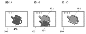
- 13A, 13 and 13C are diagrams showing a processing example of the display control unit of the display control device according to the third embodiment. It is a flowchart which shows the operation of the display control device which concerns on Embodiment 3. It is a flowchart which shows the operation of the cross-section information acquisition part of the display control apparatus which concerns on Embodiment 3.
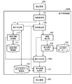
- FIG. 1 is a block diagram showing a configuration of a display control device 100 according to a first embodiment.
- the display control device 100 includes an information acquisition unit 101, a posture detection unit 102, a contact detection unit 103, a display operation determination unit 104, a display operation database 105, a display control unit 106, a display image generation unit 107, and a three-dimensional shape data storage unit 108. To be equipped.
- the display control device 100 is connected to the detection device 200 and the display device 300.
- the detection device 200 is composed of, for example, one camera or a plurality of cameras. Further, the detection device 200 may be further provided with a gyro sensor, or may be configured with only the gyro sensor.
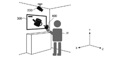
- FIG. 2 is a diagram showing a positional relationship between the detection device 200 and the display device 300 connected to the display control device 100 according to the first embodiment and the user P.
- a three-dimensional coordinate system is defined in which the plane formed by the display device 300 is the XY plane, the floor on which the user P is located is the XY plane, and the Y axis is taken in the vertical direction.
- the user P is located in front of the display device 300, that is, on the positive side of the Z axis. Further, the user P is located at a point where the holding three-dimensional object 400 is detected by the detection device 200.
- the area where the user P should be located may be determined in advance, and the area may be displayed on the floor surface.
- the information acquisition unit 101 acquires an captured image from the detection device 200.
- the information acquisition unit 101 outputs the acquired captured image to the posture detection unit 102.
- the posture detection unit 102 analyzes the captured image acquired by the information acquisition unit 101 and detects the posture of the three-dimensional object held by the user.
- the posture detection unit 102 detects a three-dimensional angle in the three-dimensional coordinate system defined above as the posture of a three-dimensional object.
- the posture detection unit 102 outputs the detected three-dimensional angle of the three-dimensional object and the captured image to the contact detection unit 103.
- the posture detection unit 102 outputs the detected three-dimensional angle of the three-dimensional object to the display image generation unit 107.
- the contact detection unit 103 analyzes the captured image input from the posture detection unit 102, and determines whether or not the user has intentionally contacted the three-dimensional object.
- the intentional contact of the user means a contact of the user other than the contact for holding the three-dimensional object.
- the contact of the right hand is referred to as the intentional contact of the user.
- the contact detection unit 103 detects the contact position and the contact type when it is determined that there is an intentional contact. It is assumed that the contact type to be detected is preset in the contact detection unit 103.
- the contact type is a double tap, a pinch out, a pinch in, or the like.
- the contact detection unit 103 determines that there is an intentional contact
- the contact detection unit 103 outputs the contact position and the contact type of the detected intentional contact to the display operation determination unit 104 as a result of the determination.
- the contact detection unit 103 outputs the determination result to the display control unit 106.
- the display operation determination unit 104 refers to the display operation database 105 and determines the display operation.
- the display operation determination unit 104 outputs the determined display operation to the display control unit 106.
- the display operation database 105 is a database in which a predefined contact type and a display operation type are associated and accumulated. The details of the display operation determination by the display operation determination unit 104 and the details of the display operation database 105 will be described later.
- the display control unit 106 is a display control condition for a two-dimensional image generated by the display image generation unit 107, which will be described later, based on the determination result input from the contact detection unit 103 or the display operation input from the display operation determination unit 104. To determine. The display control unit 106 outputs the determined display control condition to the display image generation unit 107.
- the display image generation unit 107 is viewed from the user side based on the three-dimensional shape data of the three-dimensional object stored in the three-dimensional shape data storage unit 108 and the three-dimensional angle of the three-dimensional object detected by the posture detection unit 102. Generates a two-dimensional image of a three-dimensional object. Further, the display image generation unit 107 displays the generated two-dimensional image on the display device 300 based on the display control conditions input from the display control unit 106.
- the three-dimensional shape data storage unit 108 is a storage area for storing three-dimensional shape data of a three-dimensional object.
- the two-dimensional image of the three-dimensional object generated by the display image generation unit 107 is an image of the three-dimensional object of the posture detected by the posture detection unit 102 viewed from the front of the display device 300.
- the camera which is the detection device 200, takes an image from the front side of the user P. Therefore, the display image generation unit 107 generates a two-dimensional image in which the user P sees the three-dimensional object 400 with respect to the orientation of the three-dimensional object 400 captured by the camera.
- the display image generation unit 107 holds a parameter for calculating a two-dimensional image in which the user sees the three-dimensional object based on the orientation of the three-dimensional object captured by the camera.
- the display image generation unit 107 performs calculation processing using parameters on the three-dimensional shape data of the three-dimensional object obtained based on the three-dimensional angle of the three-dimensional object, and the direction is such that the three-dimensional object is viewed from the user side. Generate a two-dimensional image.
- the display device 300 displays a two-dimensional image of a three-dimensional object generated by the display image generation unit 107. For example, as shown in FIG. 2, a two-dimensional image of the three-dimensional object 400 is displayed on the display device 300.
- FIG. 3A and 3B are diagrams showing a hardware configuration example of the display control device 100 according to the first embodiment.
- Each function of the information acquisition unit 101, the posture detection unit 102, the contact detection unit 103, the display operation determination unit 104, the display control unit 106, and the display image generation unit 107 in the display control device 100 is realized by a processing circuit. That is, the display control device 100 includes a processing circuit for realizing each of the above functions.
- the processing circuit may be a processing circuit 100a which is dedicated hardware as shown in FIG. 3A, or may be a processor 100b which executes a program stored in the memory 100c as shown in FIG. 3B. Good.
- the processing circuit 100a Is, for example, a single circuit, a composite circuit, a programmed processor, a parallel programmed processor, an ASIC (Application Specific Integrated Circuit), an FPGA (Field-programmable Gate Array), or a combination thereof.
- the functions of the information acquisition unit 101, the posture detection unit 102, the contact detection unit 103, the display operation determination unit 104, the display control unit 106, and the display image generation unit 107 may be realized by the processing circuit, or the functions of each unit may be realized. May be realized in one processing circuit collectively.
- the functions of each unit are It is realized by software, firmware, or a combination of software and firmware.
- the software or firmware is described as a program and stored in the memory 100c.
- the processor 100b reads and executes the program stored in the memory 100c, so that the information acquisition unit 101, the posture detection unit 102, the contact detection unit 103, the display operation determination unit 104, the display control unit 106, and the display image generation unit 107 Realize each function of.
- FIGS. A memory 100c for storing a program in which each step shown in 6 is to be executed as a result is provided. Further, these programs cause a computer to execute the procedure or method of the information acquisition unit 101, the posture detection unit 102, the contact detection unit 103, the display operation determination unit 104, the display control unit 106, and the display image generation unit 107. It can be said that.
- the processor 100b is, for example, a CPU (Central Processing Unit), a processing device, an arithmetic unit, a processor, a microprocessor, a microcomputer, a DSP (Digital Signal Processor), or the like.
- the memory 100c may be, for example, a non-volatile or volatile semiconductor memory such as RAM (Random Access Memory), ROM (Read Only Memory), flash memory, EPROM (Erasable Programmable ROM), and EPROM (Electrically EPROM). However, it may be a magnetic disk such as a hard disk or a flexible disk, or an optical disk such as a mini disk, a CD (Compact Disc), or a DVD (Digital Versatile Disc).
- the processing circuit in the display control device 100 can realize each of the above-mentioned functions by hardware, software, firmware, or a combination thereof.
- the contact detection unit 103 analyzes the captured image input from the posture detection unit 102, and when it is determined that the speed of the contact operation immediately before the user touches the three-dimensional object is equal to or higher than a preset threshold value, the contact detection unit 103 intentionally Determine that there was contact.
- the contact detection unit 103 performs analysis using two or more captured images captured at preset time intervals. Further, when a motion sensor (not shown) is built in the three-dimensional object and the contact detection unit 103 detects an impact strength equal to or higher than a preset threshold value by referring to the detection information of the motion sensor, intentional contact occurs. It may be configured to determine that it was present.
- the contact detection unit 103 may be configured to determine that there is an intentional contact when the preset side hand comes into contact with the three-dimensional object. For example, the contact detection unit 103 is set to indicate that the contact is intentional when the user's right hand touches the three-dimensional object. The contact detection unit 103 analyzes the captured image input from the posture detection unit 102, and determines that there was an intentional contact when the user's right hand touches a three-dimensional object. The intentional contact determination process may be realized by combining the determination methods described above.
- the contact detection unit 103 is preset with, for example, a double tap, a pinch out, a pinch in, or a two-finger tap as the contact type.
- Double tap is an operation of tapping an operation point twice in succession.
- Pinch out is an operation to widen the operation point.
- Pinch-in is an operation of pinching an operation point.
- the two-finger tap is an operation of tapping the operation point once with two fingers. It should be noted that at least one of the above-mentioned contact types may be set, and any plurality of contact types may be set.
- the above-mentioned contact type is an example, and a contact type other than the above-mentioned operation may be set.
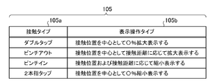
- FIG. 4 is a diagram showing a configuration example of the display operation database 105 of the display control device 100 according to the first embodiment.
- the display operation database 105 is composed of a contact type 105a and a display operation type 105b.
- the contact type 105a is, for example, a double tap, a pinch out, a pinch in, and a two-finger tap, and is a contact type set in the contact detection unit 103.
- the display operation type 105b indicates a display operation type when each contact type 105a is detected.
- a display operation type that enlarges and displays ⁇ % around the contact position is associated.
- a display operation type that enlarges and displays the contact position according to the contact distance is associated.
- a display operation type that reduces the display according to the contact position and the contact distance is associated.
- the display operation type that displays the contact position in a reduced size of 0% is associated with the contact type 105a.
- the display operation determination unit 104 refers to the display operation database 105 and displays a display operation of "displaying by ⁇ % magnified centering on the contact position". To determine.
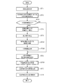
- FIG. 5 is a flowchart showing the operation of the display control device 100 according to the first embodiment.
- the process of FIG. 5 is repeated at a preset frequency (for example, 30 times per second).
- the information acquisition unit 101 acquires an captured image from the detection device 200 (step ST1) and outputs it to the posture detection unit 102.
- the posture detection unit 102 analyzes the captured image acquired in step ST1 and detects a three-dimensional angle in the three-dimensional coordinate system of the three-dimensional object held by the user (step ST2).
- the posture detection unit 102 outputs the detected three-dimensional angle of the three-dimensional object and the captured image to the contact detection unit 103. Further, the posture detection unit 102 outputs the detected three-dimensional angle of the three-dimensional object to the display image generation unit 107.
- the contact detection unit 103 analyzes the captured image input from the posture detection unit 102 and determines whether or not the user has intentionally contacted the three-dimensional object (step ST3). When there is an intentional contact (step ST3; YES), the contact detection unit 103 detects the contact position and contact type of the intentional contact using the three-dimensional angle of the three-dimensional object detected by the attitude detection unit 102. (Step ST4). The contact detection unit 103 outputs the determination result, the detected contact position and the contact type to the display operation determination unit 104. On the other hand, when there is no intentional contact (step ST3; NO), the contact detection unit 103 outputs the determination result to the display control unit 106, and proceeds to the process of step ST6.
- the display operation determination unit 104 refers to the display operation database 105 based on the contact type detected by the contact detection unit 103, and determines the display operation of the three-dimensional object (step ST5).
- the display operation determination unit 104 outputs the determined display operation to the display control unit 106.
- the display control unit 106 determines the display control conditions for the two-dimensional image based on the determination result input from the contact detection unit 103 or the display operation input from the display operation determination unit 104 (step ST6).
- the display control unit 106 outputs the determined display control condition to the display image generation unit 107.
- the display image generation unit 107 is a three-dimensional object viewed from the user side based on the three-dimensional shape data of the three-dimensional object accumulated in the three-dimensional shape data storage unit 108 and the three-dimensional angle of the three-dimensional object detected by the attitude detection unit 102. Generates a two-dimensional image of (step ST7).
- the display image generation unit 107 displays the generated two-dimensional image on the display device 300 under the display control conditions determined by the display control unit 106 (step ST8). After that, the process ends.
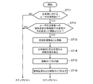
- FIG. 6 is a flowchart showing the operation of the contact detection unit 103 of the display control device 100 according to the first embodiment.
- the contact detection unit 103 analyzes the captured image and determines whether or not the user has contacted the three-dimensional object (step ST11).
- the contact detection unit 103 determines whether or not the speed of the contact operation immediately before the contact of the user is equal to or higher than a preset threshold value (step ST12). When the speed of the contact operation immediately before the user's contact is equal to or higher than a preset threshold value (step ST12; YES), the contact detection unit 103 determines that the user has intentionally contacted (step ST13).
- the contact detection unit 103 detects the contact position of the user by using the analysis result of the captured image and the three-dimensional angle of the three-dimensional object detected by the posture detection unit 102 (step ST14).
- the contact detection unit 103 determines the contact type of the user based on the analysis result of the captured image (step ST15).
- the contact detection unit 103 outputs the contact position detected in step ST14 and the contact type determined in step ST15 to the display operation determination unit 104 (step ST16). After that, the process proceeds to the process of step ST5 in the flowchart of FIG.
- step ST11; NO when there is no user contact (step ST11; NO), or when the speed of the contact operation immediately before the user contact is not equal to or higher than a preset threshold value (step ST12; NO), the processing is performed in the flowchart of FIG. The process proceeds to step ST6.
- the posture detection unit 102 determines whether or not the user intentionally contacts the three-dimensional object held by the user with the posture detection unit 102 that detects the three-dimensional angle of the three-dimensional object.
- a two-dimensional image of a three-dimensional object based on the contact detection unit 103 that detects the contact position and contact type of intentional contact when it is determined that the contact is intentionally made, and the detected contact position and contact type.
- the display operation determination unit 104 that determines the display operation of the two-dimensional image
- the display control unit 106 determines the display control conditions of the two-dimensional image based on the determination result of intentional contact or the determined display operation.
- a 2D image calculated to be obtained when the 3D object is visually recognized from the user side is generated, and the generated 2 It is configured to include a display image generation unit 107 that displays a three-dimensional image under display control conditions determined by the display control unit.
- the information obtained by the user by actually visually recognizing the three-dimensional object and the information to be displayed on the screen are linked and displayed. Can be done.
- the user can recognize the three-dimensional object that is actually visually recognized by matching the information of the three-dimensional object displayed on the screen.
- the contact detection unit 103 is based on a user's double tap operation, pinch out operation, pinch in operation, or two-finger tap operation.
- the dimensional image is configured to determine the display operation for enlarging or reducing the contact position.
- FIG. 7 is a block diagram showing a configuration of the display control device 100A according to the second embodiment.
- the display control device 100A of the second embodiment is provided with the accompanying information acquisition unit 109 and the accompanying information database 110 added to the display control device 100 shown in the first embodiment. Further, the display control unit 106a is provided in place of the display control unit 106 of the display control device 100 shown in the first embodiment.
- the same or corresponding parts as the components of the display control device 100 according to the first embodiment are designated by the same reference numerals as those used in the first embodiment, and the description thereof will be omitted or simplified. ..
- the incidental information acquisition unit 109 refers to the incidental information database 110 and acquires the incidental information to be displayed.
- the incidental information database 110 is a database in which a predetermined contact type, contact position information, and incidental information are associated and accumulated.
- the incidental information acquisition unit 109 acquires the incidental information associated with the corresponding contact position information.
- the accompanying information acquisition unit 109 outputs the acquired incidental information and contact position information to the display control unit 106a.
- the display control unit 106a is a two-dimensional image generated by the display image generation unit 107 based on the determination result input from the contact detection unit 103 or the display operation input from the display operation determination unit 104 as in the first embodiment. Determine the image display control conditions. Further, the display control unit 106a determines display control conditions for displaying the incidental information acquired by the incidental information acquisition unit 109 on the two-dimensional image according to the contact position information.
- FIG. 8 is a diagram showing a configuration example of the incidental information database 110 of the display control device 100A according to the second embodiment.
- the accompanying information database 110 is composed of the contact type 110a, the contact position information 110b, and the accompanying information 110c.
- the contact type 110a is a contact type other than the type set in the contact type 105a of the display operation database 105, and is a contact type set in the contact detection unit 103.
- the contact type 110a is, for example, a single tap.
- the contact position information 110b indicates the area information on the three-dimensional object with which the contact has occurred.
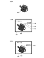
- FIG. 9 is an explanatory diagram of contact position information 110b of the incidental information database 110 of the display control device 100A according to the second embodiment.
- FIG. 9A shows an example in which the region on the three-dimensional object 400 is divided into four regions, region A, region B, region C, and region D, for each part of the three-dimensional object 400.
- the contact position information 110b is the area A, it indicates that the user has contacted the area A.
- the area to be divided is not limited to four, and an arbitrary number of divided areas can be set.
- the incidental information 110c of the incidental information database 110 indicates the incidental information to be displayed. For example, it indicates that the accompanying information "name b" is displayed when the contact type input from the contact detection unit 103 is a single tap and the contact position is within the area B.
- the incidental information acquisition unit 109 outputs the acquired incidental information 110c to the display control unit 106a together with the information indicating the contact position information 110b. Specifically, the incidental information acquisition unit 109 outputs, for example, the incidental information "name b" to the display control unit 106a together with the contact position information "area B".
- the display control unit 106a determines the display control conditions for displaying the accompanying information 110c in the display area of the contact position information 110b on the two-dimensional image.
- the display area of the contact position information 110b is a region close to the region indicated by the contact position information 110b and does not overlap with the two-dimensional image of the three-dimensional object.
- the display control unit 106a determines the display control condition for displaying the name b in the area close to the area B and not overlapping with the two-dimensional image of the three-dimensional object 400 shown in FIG. 9A.
- the incidental information acquisition unit 109 may output the acquired incidental information to the display control unit 106a together with the contact position input from the contact detection unit 103, for example.
- the display control unit 106a determines the display control condition for displaying the accompanying information at a point close to the contact position on the two-dimensional image and not overlapping with the display of the three-dimensional object. Further, the display control unit 106a determines a display control condition for displaying an image indicating a portion operated by the user superimposed on the contact position on the two-dimensional image.
- an image 110d showing a portion operated by the user is superimposed on the display of the three-dimensional object 400 to display a double circle image.
- the display control condition for displaying the leader line 110e connecting the image 110d indicating the location where the user has performed the operation and the accompanying information 110c may be determined.
- the display control unit 106a may be configured to highlight and display the region indicated by the contact position information 110b on the two-dimensional image. As shown in FIG. 9C, for example, highlight display is performed in which the display color of the area B is set to a color brighter than that of the other areas.
- the display control unit 106a and the accompanying information acquisition unit 109 in the display control device 100A may be a processing circuit 100a which is dedicated hardware as shown in FIG. 3A, or may be stored in the memory 100c as shown in FIG. 3B. It may be the processor 100b that executes the program.
- the functions of the display control unit 106a and the incidental information acquisition unit 109 are software, firmware, or software and firmware. It is realized by the combination.
- the software or firmware is described as a program and stored in the memory 100c.
- the processor 100b realizes the functions of the display control unit 106a and the accompanying information acquisition unit 109 by reading and executing the program stored in the memory 100c. That is, the display control unit 106a and the accompanying information acquisition unit 109 store a memory 100c for storing a program in which each step shown in FIG. 10, which will be described later, is eventually executed when the processor 100b executes the display control unit 106a. Be prepared. Further, it can be said that these programs cause the computer to execute the procedure or method of the display control unit 106a and the accompanying information acquisition unit 109.
- the functions of the display control unit 106a and the accompanying information acquisition unit 109 may be realized by dedicated hardware and partly by software or firmware.
- the processing circuit 100a in the display control device 100A can realize each of the above-mentioned functions by hardware, software, firmware, or a combination thereof.
- FIG. 10 is a flowchart showing the operation of the display control device 100A according to the second embodiment.
- the same steps as the flowchart of the first embodiment shown in FIG. 5 are designated by the same reference numerals, and the description thereof will be omitted.
- the accompanying information acquisition unit 109 determines which of the preset regions the contact position detected by the contact detection unit 103 exists (step ST5). Step ST21).
- the incidental information acquisition unit 109 refers to the incidental information database 110 based on the contact type detected by the contact detection unit 103 and the area determined in step ST21, and acquires the incidental information to be displayed (step ST22).
- the incidental information acquisition unit 109 outputs the acquired incidental information and the contact position information indicating the area to the display control unit 106a.
- the display control unit 106a determines the display control conditions for the two-dimensional image based on the determination result input from the contact detection unit 103 or the display operation input from the display operation determination unit 104 (step ST6). When there is accompanying information, the display control unit 106a determines a display control condition for displaying the incidental information acquired by the incidental information acquisition unit 109 in the display area corresponding to the contact position information in the two-dimensional image (step). ST23). If there is no accompanying information, the display control unit 106a omits the process of step ST23. After that, the process proceeds to the process of step ST7.
- a display control condition for displaying an image showing a portion operated by the user in an superimposed manner may be determined. Further, in the process of step ST23 described above, the display control condition for displaying the leader line connecting the image indicating the location where the user has performed the operation and the accompanying information may be determined. Further, in the process of step ST23 described above, the display control condition for highlighting the area indicated by the contact position information may be determined.
- the contact detection unit 103 displays the display based on the contact position and the contact type detected when it is determined that the user intentionally contacts the three-dimensional object.
- An incidental information acquisition unit 109 for acquiring power incidental information is provided, and the display control unit 106a displays the incidental information on a two-dimensional image of a three-dimensional object based on the contact position information associated with the acquired incidental information.
- the contact type for determining the control conditions and for the accompanying information acquisition unit 109 to acquire the incidental information is configured to be different from the contact type for the display operation determination unit 104 to determine the display operation.
- the information obtained by the user by actually visually recognizing the three-dimensional object and the information to be displayed on the screen are linked, and the accompanying information corresponding to the user's contact is displayed on the screen according to the user's contact position. be able to.
- the display control unit 106a determines the display control condition for displaying the image indicating the contact position superimposed on the two-dimensional image of the three-dimensional object based on the detected contact position. It was configured as follows. As a result, it is possible to clearly indicate to the user that the accompanying information corresponding to the contact position of the user is displayed.
- the display control unit 106a is configured to determine the display control condition for highlighting the area indicated by the contact position information in the two-dimensional image of the three-dimensional object. As a result, it is possible to clearly indicate to the user that the accompanying information corresponding to the contact area of the user is displayed.
- the display control unit 106a determines a display control condition for displaying incidental information in a region close to the region indicated by the contact position information in the two-dimensional image of the three-dimensional object. Configured. As a result, it is possible to clearly indicate to the user that the accompanying information corresponding to the contact position of the user is displayed.
- FIG. 11 is a block diagram showing a configuration of the display control device 100B according to the third embodiment.
- the display control device 100B of the third embodiment is provided with an operation determination unit 111, a cross-section information acquisition unit 112, and a cross-section information storage unit 113 added to the display control device 100 shown in the first embodiment.
- the display control unit 106b is provided in place of the display control unit 106 of the display control device 100 shown in the first embodiment.
- the same or corresponding parts as the components of the display control device 100 according to the first embodiment are designated by the same reference numerals as those used in the first embodiment, and the description thereof will be omitted or simplified. ..
- the operation determination unit 111 analyzes the captured image acquired by the information acquisition unit 101, and determines whether or not a preset user's hand shape, which instructs the display of the cross section of the three-dimensional object, has been detected.
- the preset hand shape that instructs the display of the cross section of the three-dimensional object is, for example, the shape of a hand in which the hand is spread out and a surface is formed by the palm.
- the preset shape of the hand that instructs the display of the cross section of the three-dimensional object is not limited to the shape in which the hand is spread, and can be appropriately set.
- the operation determination unit 111 determines that the preset hand shape has been detected, it determines that the user has performed an operation instructing the display of the cross section of the three-dimensional object.
- the operation determination unit 111 acquires the three-dimensional shape data of the three-dimensional object accumulated in the three-dimensional shape data storage unit 108, and defines the three-dimensional coordinate system for the three-dimensional object.
- the operation determination unit 111 detects the position of the operation point and the angle of the surface formed by the contacted palm in the defined three-dimensional coordinate system.
- the operation determination unit 111 outputs the detected position information of the operation point and the angle information of the surface to the cross-section information acquisition unit 112.
- a motion sensor (not shown) is built in the three-dimensional object, and when the operation determination unit 111 detects an impact strength equal to or greater than a threshold value obtained from the motion sensor, the user instructs the display of the cross section of the three-dimensional object. It may be determined that the operation has been performed. Further, the operation determination unit 111 may detect the position of the operation point from the position detected by the motion sensor and detect the angle of the surface from the angle of impact detected by the motion sensor.
- the cross-section information acquisition unit 112 sets the user's operation surface using the input position information of the operation point and the angle information of the surface.
- the operation surface of the user is set as, for example, a surface that approximates the surface formed by the palm of the user.
- the cross-section information acquisition unit 112 refers to the cross-section information stored in the cross-section information storage unit 113, and determines the cross-section that most closely resembles the set user's operation surface.
- the cross-section information acquisition unit 112 outputs the cross-section information of the determined cross-section to the display control unit 106b. The details of the operation determination unit 111 and the cross-section information acquisition unit 112 will be described later.
- the cross-section information storage unit 113 stores cross-section information in which the display information of the cross-section obtained when the three-dimensional object is cut on a preset surface and the information indicating the position where the three-dimensional object is cut are linked. .. Information indicating at what position the three-dimensional object is cut is defined in the three-dimensional coordinate system of the three-dimensional object.
- the display control unit 106b is a two-dimensional device generated by the display image generation unit 107 based on the determination result input from the contact detection unit 103 or the display operation input from the display operation determination unit 104 as in the first embodiment. Determine the image display control conditions. Further, the display control unit 106b displays information indicating a cross section obtained when the displayed three-dimensional object is cut by a designated surface when the cross section information is input from the cross section information acquisition unit 112. To determine.
- the display control unit 106b, the operation determination unit 111, and the cross-section information acquisition unit 112 in the display control device 100B may be a processing circuit 100a which is dedicated hardware as shown in FIG. 3A, or may be a processing circuit 100a as shown in FIG. 3B. It may be a processor 100b that executes a program stored in the memory 100c.
- the functions of the display control unit 106b, the operation determination unit 111, and the cross-section information acquisition unit 112 are the processors 100b
- the functions of the display control unit 106b, the operation determination unit 111, and the cross-section information acquisition unit 112 are It is achieved by software, firmware, or a combination of software and firmware.
- the software or firmware is described as a program and stored in the memory 100c.
- the processor 100b realizes the functions of the display control unit 106b, the operation determination unit 111, and the cross-section information acquisition unit 112 by reading and executing the program stored in the memory 100c.
- the processing circuit 100a in the display control device 100B can realize each of the above-mentioned functions by hardware, software, firmware, or a combination thereof.
- FIG. 12 is a diagram showing a processing example of the operation determination unit 111 and the cross-section information acquisition unit 112 of the display control device 100B according to the third embodiment.
- FIG. 12A shows a case where the user P operates the three-dimensional object 400 with a preset hand shape.
- FIG. 12B shows an operation area 400a in which the hand of the user P comes into contact with the three-dimensional object 400 by the user operation of FIG. 12A.
- FIG. 12C is a diagram showing a comparison between the user's operation surface and each cross section stored in the cross section information storage unit 113. Note that FIGS. 12B and 12C show a plan view of the three-dimensional object 400 as viewed from above.
- the user P performs an operation of instructing the display of the cross section of the three-dimensional object 400 with a preset hand shape.
- the XYZ axes of FIG. 12A are a three-dimensional coordinate system defined for a three-dimensional object.
- the hand of the user P comes into contact with the operation area 400a on the three-dimensional object 400 as shown in FIG. 12B.
- the operation determination unit 111 detects the center of the operation area 400a as the operation point 400b. If the operation area 400a is obtained in advance as a point, the operation determination unit 111 detects the point as the operation point 400b.
- the operation point 400b is represented by a coordinate value in the three-dimensional coordinate system of the three-dimensional object 400.
- the operation determination unit 111 detects the angle of the palm imaged by the detection device 200 with respect to the three-dimensional object.
- the angle of the palm with respect to the three-dimensional object is represented by, for example, a space vector in the three-dimensional coordinate system of the three-dimensional object.
- the cross-section information acquisition unit 112 sets the user's operation surface from the operation point detected by the operation determination unit 111 and the angle of the palm with respect to the three-dimensional object.
- the user's operation surface is defined by the three-dimensional coordinate system of the three-dimensional object.
- the cross-section information acquisition unit 112 compares the set user's operation surface with the cross-section stored in the cross-section information storage unit 113, and determines the cross-section that most closely resembles the user's operation surface.
- the cross-section information acquisition unit 112 is the cross section that most closely approximates the user's operation surface based on the difference in angle between the user's operation surface and the accumulated cross section and the difference in the distance between the user's operation surface and the accumulated cross section. To determine.
- the difference in angle between the user's operation surface and the accumulated cross section is the difference between the angle of the normal vector of the user's operation surface and the angle of the accumulated cross section normal vector.
- the difference in the distance between the user's operation surface and the accumulated cross section is the position of the operation point of the three-dimensional object and each line segment of the line segment set that approximates the outer circumference of the accumulated cross section to a straight line by any method. It shall be the smallest of the distances.
- the cross-section information acquisition unit 112 calculates the shortest distance 501a between the operation point 400b and the curve of the surface of the first cross-section 501. Similarly, the cross-section information acquisition unit 112 calculates the shortest distance 502a between the operation point 400b and the curve of the surface of the second cross-section 502.
- the cross-section information acquisition unit 112 appropriately weights and adds the calculated difference in angle between the user's operation surface and the accumulated cross-section and the difference in the distance between the user's operation surface and the accumulated cross-section, and adds the user. Calculate the degree of approximation with the operation surface of.
- the cross-section information acquisition unit 112 determines the cross-section that most closely approximates the user's operation surface based on the calculated degree of approximation. In the example of FIG. 12C, the cross-section information acquisition unit 112 determines the first cross-section 501 as the cross-section that most closely resembles the user's operating surface.
- FIG. 13 is a diagram showing a processing example of the display control unit 106b of the display control device 100B according to the third embodiment.
- the display control unit 106b determines, for example, a display condition for displaying an animation in which information indicating the cross-section is displayed as a result of cutting a three-dimensional object on a certain surface.
- 13A to 13B are diagrams showing an animation example of screen transition when displaying information indicating a cross section of a three-dimensional object 400.
- the display control unit 106b divides the three-dimensional object 400 into a front portion 401 and a rear portion 402 with respect to the three-dimensional object 400 shown in FIG. 13A, and the front portion 401 is a screen of the display device 300.
- the display control condition for which the display transitions so as to move downward and disappear from the screen is determined.
- the display control unit 106b determines the display control conditions indicating the cross-sectional configuration of the non-moving rear portion 402.
- the front portion 401 shows the transition of the display disappearing to the lower side of the screen of the display device 300, but the disappearing direction can be arbitrarily set.
- the display control condition may be set to immediately display the information indicating the cross section without performing the screen transition when displaying the information indicating the cross section of the three-dimensional object 400.
- FIG. 14 is a flowchart showing the operation of the display control device 100B according to the third embodiment.
- the cross-section information acquisition unit 112 detects the operation point and the surface formed by the palm from the captured image of the detection device 200 will be described as an example.
- the information acquisition unit 101 acquires an captured image from the detection device 200 (step ST31) and outputs it to the operation determination unit 111.
- the operation determination unit 111 analyzes the captured image acquired in step ST31 and determines whether or not a preset hand shape has been detected (step ST32). If the preset hand shape is not detected (step ST32; NO), the process proceeds to step ST2 of the flowchart of FIG. On the other hand, when the preset hand shape is detected (step ST32; YES), the operation determination unit 111 acquires the three-dimensional shape data of the three-dimensional object accumulated in the three-dimensional shape data storage unit 108, and the solid. A three-dimensional coordinate system of an object is defined (step ST33). The operation determination unit 111 detects the position of the operation point and the angle of the surface formed by the contacted palm in the three-dimensional coordinate system defined in step ST33 (step ST34), and outputs the output to the cross-section information acquisition unit 112.
- the cross-section information acquisition unit 112 sets the user's operation surface using the input position information of the operation point and the angle information of the surface (step ST35).
- the cross-section information acquisition unit 112 determines a cross-section that most closely resembles the user's operation surface set in step ST35 from the cross-sections stored in the cross-section information storage unit 113 (step ST36).
- the cross-section information acquisition unit 112 acquires the cross-section information of the cross-section determined in step ST36 from the cross-section information storage unit 113 (step ST37), and outputs the cross-section information to the display control unit 106b.
- the display control unit 106b determines the display control conditions for displaying the input cross-sectional information with respect to the displayed two-dimensional image (step ST38).
- the display image generation unit 107 displays the generated two-dimensional image on the display device 300 under the display control conditions determined by the display control unit 106b (step ST39).
- step ST40 determines whether or not the input for hiding the displayed cross-section information acquired by the information acquisition unit 101 has been made. If no input is made to hide the displayed cross-section information (step ST40; NO), the determination process of step ST40 is repeated. On the other hand, when the input for hiding the displayed cross-sectional information is performed (step ST40; YES), the process proceeds to step ST2 of the flowchart of FIG.
- Inputs for hiding the cross-section information in step ST40 include, for example, pressing a separately prepared button, inputting a preset contact type, and detecting an acceleration sensor (not shown) indicating that a three-dimensional object has been shaken. It is an input of information.
- the preset contact type is a contact type other than the type set in the contact type 105a of the display operation database 105 and the type other than the type set in the contact type 110a of the accompanying information database 110.
- FIG. 15 is a flowchart showing the operation of the cross-section information acquisition unit 112 of the display control device 100B according to the third embodiment.
- the cross-section information acquisition unit 112 calculates the difference in angle and the difference in distance between the user's operation surface set in step ST35 and the cross-section stored in the cross-section information storage unit 113 (step ST41).
- the cross-section information acquisition unit 112 determines whether or not the difference in angle and the difference in distance have been calculated for all the cross-sections corresponding to the three-dimensional objects stored in the cross-section information storage unit 113 (step ST42). If the calculation has not been performed for all the cross sections corresponding to the three-dimensional object (step ST42; NO), the process returns to the process of step ST41.
- step ST42 when all the cross sections corresponding to the three-dimensional object are calculated (step ST42; YES), the cross-section information acquisition unit 112 weights and adds the difference in angle and the difference in distance calculated in step ST42 to obtain the degree of approximation. Is calculated (step ST43).
- the cross-section information acquisition unit 112 determines the cross-section that most closely resembles the user's operation surface based on the degree of approximation calculated in step ST43 (step ST44). After that, the process proceeds to step ST37 of the flowchart of FIG.
- the operation point of the user's hand with respect to the three-dimensional object is determined. Based on the position and the operation determination unit 111 that detects the angle of the user's hand with respect to the three-dimensional object, the position of the detected operation point, and the angle with respect to the three-dimensional object, it is displayed from the cross sections of the three-dimensional object accumulated in advance.
- the display control unit 106b includes a cross-section information acquisition unit 112 that determines the cross-section of the three-dimensional object to be output and acquires information indicating the cross-section, and information indicating the acquired cross-section of the three-dimensional object in the two-dimensional image of the three-dimensional object. It is configured to determine the display control conditions for displaying.
- the user can display information indicating the cross section of the three-dimensional object only by taking a preset hand shape.
- the present invention allows free combination of each embodiment, modification of any component of each embodiment, or omission of any component in each embodiment within the scope of the invention. It is possible.
- the display control device is a device for displaying information about the three-dimensional object to an operator who operates the three-dimensional object, and is applied to the case where the operator operates while picking up the three-dimensional object. Is preferable.
- 100, 100A, 100B display control device 101 information acquisition unit, 102 posture detection unit, 103 contact detection unit, 104 display operation determination unit, 105 display operation database, 106, 106a, 106b display control unit, 107 display image generation unit, 108 3D shape data storage unit, 109 incidental information acquisition unit, 110 incidental information database, 111 operation judgment unit, 112 cross-section information acquisition unit, 113 cross-section information storage unit.
Landscapes
- Engineering & Computer Science (AREA)
- General Engineering & Computer Science (AREA)
- Theoretical Computer Science (AREA)
- Human Computer Interaction (AREA)
- Physics & Mathematics (AREA)
- General Physics & Mathematics (AREA)
- User Interface Of Digital Computer (AREA)
Abstract
ユーザが保持する立体物の3次元角度を検出する姿勢検出部(102)と、立体物に対してユーザが意図的に接触したか否か判定を行い、意図的に接触したと判定した場合に、意図的な接触の接触位置および接触タイプを検出する接触検出部(103)と、検出された接触位置および接触タイプに基づいて、立体物の2次元画像の表示操作を決定する表示操作決定部(104)と、意図的に接触したかの判定結果、または決定された表示操作に基づいて、2次元画像の表示制御条件を決定する表示制御部(106)と、予め蓄積された立体物の3次元形状データと、検出された立体物の3次元角度とから、立体物をユーザ側から視認した場合に得られると算出される2次元画像を生成し、生成した2次元画像を表示制御部が決定した表示制御条件で表示する表示画像生成部(107)とを備える。
Description
この発明は、立体物を操作する操作者に、当該立体物に関する情報を表示する技術に関するものである。
従来、立体物を自由な方向から視認可能なように、立体物を様々な角度から見込んだ複数の2次元画像を用意し、操作者の指示に従って用意された2次元画像の中から適宜選択して表示する技術が存在する。
例えば、特許文献1には、操作者がマニピュレータ部を操作することにより、当該操作に対応した方向より立体物を撮像した画像に相当する2次元画像を、3次元形状と表示画像とを用いて表示部の最小表示単位時間以下で生成する立体物表示装置が記載されている。特許文献1の立体物表示装置では、操作者にあたかも立体物を手に持っているような仮想現実感を与える画像表示を行うことができる。
例えば、特許文献1には、操作者がマニピュレータ部を操作することにより、当該操作に対応した方向より立体物を撮像した画像に相当する2次元画像を、3次元形状と表示画像とを用いて表示部の最小表示単位時間以下で生成する立体物表示装置が記載されている。特許文献1の立体物表示装置では、操作者にあたかも立体物を手に持っているような仮想現実感を与える画像表示を行うことができる。
上述した特許文献1の立体物表示装置では、立体物として、工芸品等の操作者が手に取ることができないものを対象としており、操作用にマニピュレータ部を設けている。そのため、特許文献1の立体物表示装置において、操作者が手に取った立体物を対象とした場合に、操作者が実際の立体物を持って視認して得た情報と、操作者がマニピュレータ部を操作して画面上に表示された情報とを一致させることが困難であるという課題があった。
この発明は、上記のような課題を解決するためになされたもので、ユーザが手に取った立体物の情報を画面上に表示する場合に、立体物を実際に視認してユーザが得る情報と、画面上に表示させる情報とを連携させることを目的とする。
この発明に係る表示制御装置は、ユーザが保持する立体物の3次元角度を検出する姿勢検出部と、立体物に対してユーザが意図的に接触したか否か判定を行い、意図的に接触したと判定した場合に、意図的な接触の接触位置および接触タイプを検出する接触検出部と、接触検出部が検出した接触位置および接触タイプに基づいて、立体物の2次元画像の表示操作を決定する表示操作決定部と、接触検出部の判定結果、または表示操作決定部が決定した表示操作に基づいて、2次元画像の表示制御条件を決定する表示制御部と、予め蓄積された立体物の3次元形状データと、姿勢検出部が検出した立体物の3次元角度とから、立体物をユーザ側から視認した場合に得られると算出される2次元画像を生成し、生成した2次元画像を表示制御部が決定した表示制御条件で表示する表示画像生成部とを備えるものである。
この発明によれば、ユーザが手に取った立体物の情報を画面上に表示する場合に、立体物を実際に視認してユーザが得る情報と、画面上に表示させる情報とを連携させて表示する制御を行うことができる。これにより、ユーザはより直感的で分かりやすく立体物の情報を得ることができる。
以下、この発明をより詳細に説明するために、この発明を実施するための形態について、添付の図面に従って説明する。
実施の形態1.
図1は、実施の形態1に係る表示制御装置100の構成を示すブロック図である。
表示制御装置100は、情報取得部101、姿勢検出部102、接触検出部103、表示操作決定部104、表示操作データベース105、表示制御部106、表示画像生成部107および3次元形状データ蓄積部108を備える。
表示制御装置100は、検出装置200および表示装置300と接続される。検出装置200は、例えば、1台のカメラまたは複数台のカメラで構成される。また検出装置200は、さらにジャイロセンサを備えて構成してもよいし、ジャイロセンサのみで構成してもよい。
実施の形態1.
図1は、実施の形態1に係る表示制御装置100の構成を示すブロック図である。
表示制御装置100は、情報取得部101、姿勢検出部102、接触検出部103、表示操作決定部104、表示操作データベース105、表示制御部106、表示画像生成部107および3次元形状データ蓄積部108を備える。
表示制御装置100は、検出装置200および表示装置300と接続される。検出装置200は、例えば、1台のカメラまたは複数台のカメラで構成される。また検出装置200は、さらにジャイロセンサを備えて構成してもよいし、ジャイロセンサのみで構成してもよい。
図2は、実施の形態1に係る表示制御装置100に接続された検出装置200および表示装置300と、ユーザPとの位置関係を示す図である。
以下の説明では、表示装置300が形成する平面をX-Y平面とし、ユーザPが位置する床面をX-Z平面とし、鉛直方向にY軸を取った3次元座標系を定義する。例えば、ユーザPは、表示装置300の正面、即ちZ軸の正方向側に位置する。また、ユーザPは、保持している立体物400が検出装置200から検出される地点に位置する。ユーザPが位置すべき領域を予め決定しておき、当該領域を床面に表示してもよい。
以下の説明では、表示装置300が形成する平面をX-Y平面とし、ユーザPが位置する床面をX-Z平面とし、鉛直方向にY軸を取った3次元座標系を定義する。例えば、ユーザPは、表示装置300の正面、即ちZ軸の正方向側に位置する。また、ユーザPは、保持している立体物400が検出装置200から検出される地点に位置する。ユーザPが位置すべき領域を予め決定しておき、当該領域を床面に表示してもよい。
以下では、検出装置200が1台のカメラで構成される場合を例に説明する。
情報取得部101は、検出装置200から撮像画像を取得する。情報取得部101は、取得した撮像画像を姿勢検出部102に出力する。姿勢検出部102は、情報取得部101が取得した撮像画像を解析し、ユーザが保持する立体物の姿勢を検出する。姿勢検出部102は、立体物の姿勢として、上記で定義した3次元座標系における3次元角度を検出する。姿勢検出部102は、検出した立体物の3次元角度および撮像画像を接触検出部103に出力する。姿勢検出部102は、検出した立体物の3次元角度を表示画像生成部107に出力する。
情報取得部101は、検出装置200から撮像画像を取得する。情報取得部101は、取得した撮像画像を姿勢検出部102に出力する。姿勢検出部102は、情報取得部101が取得した撮像画像を解析し、ユーザが保持する立体物の姿勢を検出する。姿勢検出部102は、立体物の姿勢として、上記で定義した3次元座標系における3次元角度を検出する。姿勢検出部102は、検出した立体物の3次元角度および撮像画像を接触検出部103に出力する。姿勢検出部102は、検出した立体物の3次元角度を表示画像生成部107に出力する。
接触検出部103は、姿勢検出部102から入力された撮像画像を解析し、立体物に対するユーザの意図的な接触があったか否か判定を行う。ここで、ユーザの意図的な接触とは、立体物を保持するための接触以外の、ユーザの接触をいう。例えば、ユーザが立体物を左手で保持している状態で、右手が立体物に接触した場合に、当該右手の接触をユーザの意図的な接触という。接触検出部103は、意図的な接触があったと判定した場合に、接触位置および接触タイプを検出する。接触検出部103には、検出すべき接触タイプが予め設定されているものとする。接触タイプとは、ダブルタップ、ピンチアウト、またはピンチイン等である。接触検出部103による意図的な接触の判定、および接触タイプの詳細については、後述する。
接触検出部103は、意図的な接触があったと判定した場合に、当該判定結果、検出された意図的な接触の接触位置および接触タイプを表示操作決定部104に出力する。一方、接触検出部103は、意図的な接触がなかったと判定した場合に、当該判定結果を表示制御部106に出力する。
接触検出部103は、意図的な接触があったと判定した場合に、当該判定結果、検出された意図的な接触の接触位置および接触タイプを表示操作決定部104に出力する。一方、接触検出部103は、意図的な接触がなかったと判定した場合に、当該判定結果を表示制御部106に出力する。
表示操作決定部104は、接触検出部103から意図的な接触があったとの判定結果、接触位置および接触タイプが入力された場合、表示操作データベース105を参照し、表示操作を決定する。表示操作決定部104は、決定した表示操作を表示制御部106に出力する。表示操作データベース105は、予め定義された接触タイプと、表示操作タイプとを紐づけて蓄積したデータベースである。表示操作決定部104による表示操作の決定の詳細、および表示操作データベース105の詳細については、後述する。
表示制御部106は、接触検出部103から入力された判定結果、または表示操作決定部104から入力された表示操作に基づいて、後述する表示画像生成部107が生成する2次元画像の表示制御条件を決定する。表示制御部106は、決定した表示制御条件を表示画像生成部107に出力する。
表示画像生成部107は、3次元形状データ蓄積部108に蓄積された立体物の3次元形状データと、姿勢検出部102が検出した立体物の3次元角度とに基づいて、ユーザ側から見た立体物の2次元画像を生成する。また、表示画像生成部107は、生成した2次元画像を、表示制御部106から入力された表示制御条件に基づいて、表示装置300に表示する。3次元形状データ蓄積部108は、立体物の3次元形状データを蓄積する蓄積領域である。
表示画像生成部107が生成する立体物の2次元画像は、姿勢検出部102で検出された姿勢の立体物を、表示装置300正面から見た画像である。
具体的には、図2に示すように検出装置200であるカメラはユーザPの正面側から撮像する。そのため、表示画像生成部107は、カメラが撮像した立体物400の向きに対して、ユーザP側から立体物400を見た向きとなる2次元画像を生成する。表示画像生成部107は、カメラが撮像した立体物の向きに基づいて、ユーザ側から立体物を見た向きとなる2次元画像を算出するためのパラメータを保持する。表示画像生成部107は、立体物の3次元角度に基づいて得られた立体物の3次元形状データに対して、パラメータを用いた算出処理を行い、ユーザ側から立体物を見た向きとなる2次元画像を生成する。
具体的には、図2に示すように検出装置200であるカメラはユーザPの正面側から撮像する。そのため、表示画像生成部107は、カメラが撮像した立体物400の向きに対して、ユーザP側から立体物400を見た向きとなる2次元画像を生成する。表示画像生成部107は、カメラが撮像した立体物の向きに基づいて、ユーザ側から立体物を見た向きとなる2次元画像を算出するためのパラメータを保持する。表示画像生成部107は、立体物の3次元角度に基づいて得られた立体物の3次元形状データに対して、パラメータを用いた算出処理を行い、ユーザ側から立体物を見た向きとなる2次元画像を生成する。
表示装置300は、表示画像生成部107が生成した立体物の2次元画像を表示する。例えば図2に示したように、表示装置300に立体物400の2次元画像が表示される。
次に、表示制御装置100のハードウェア構成例を説明する。
図3Aおよび図3Bは、実施の形態1に係る表示制御装置100のハードウェア構成例を示す図である。
表示制御装置100における情報取得部101、姿勢検出部102、接触検出部103、表示操作決定部104、表示制御部106および表示画像生成部107の各機能は、処理回路により実現される。即ち、表示制御装置100は、上記各機能を実現するための処理回路を備える。当該処理回路は、図3Aに示すように専用のハードウェアである処理回路100aであってもよいし、図3Bに示すようにメモリ100cに格納されているプログラムを実行するプロセッサ100bであってもよい。
図3Aおよび図3Bは、実施の形態1に係る表示制御装置100のハードウェア構成例を示す図である。
表示制御装置100における情報取得部101、姿勢検出部102、接触検出部103、表示操作決定部104、表示制御部106および表示画像生成部107の各機能は、処理回路により実現される。即ち、表示制御装置100は、上記各機能を実現するための処理回路を備える。当該処理回路は、図3Aに示すように専用のハードウェアである処理回路100aであってもよいし、図3Bに示すようにメモリ100cに格納されているプログラムを実行するプロセッサ100bであってもよい。
図3Aに示すように、情報取得部101、姿勢検出部102、接触検出部103、表示操作決定部104、表示制御部106および表示画像生成部107が専用のハードウェアである場合、処理回路100aは、例えば、単一回路、複合回路、プログラム化したプロセッサ、並列プログラム化したプロセッサ、ASIC(Application Specific Integrated Circuit)、FPGA(Field-programmable Gate Array)、またはこれらを組み合わせたものが該当する。情報取得部101、姿勢検出部102、接触検出部103、表示操作決定部104、表示制御部106および表示画像生成部107の各部の機能それぞれを処理回路で実現してもよいし、各部の機能をまとめて1つの処理回路で実現してもよい。
図3Bに示すように、情報取得部101、姿勢検出部102、接触検出部103、表示操作決定部104、表示制御部106および表示画像生成部107がプロセッサ100bである場合、各部の機能は、ソフトウェア、ファームウェア、またはソフトウェアとファームウェアとの組み合わせにより実現される。ソフトウェアまたはファームウェアはプログラムとして記述され、メモリ100cに格納される。プロセッサ100bは、メモリ100cに記憶されたプログラムを読み出して実行することにより、情報取得部101、姿勢検出部102、接触検出部103、表示操作決定部104、表示制御部106および表示画像生成部107の各機能を実現する。即ち、情報取得部101、姿勢検出部102、接触検出部103、表示操作決定部104、表示制御部106および表示画像生成部107は、プロセッサ100bにより実行されるときに、後述する図5および図6に示す各ステップが結果的に実行されることになるプログラムを格納するためのメモリ100cを備える。また、これらのプログラムは、情報取得部101、姿勢検出部102、接触検出部103、表示操作決定部104、表示制御部106および表示画像生成部107の手順または方法をコンピュータに実行させるものであるともいえる。
ここで、プロセッサ100bとは、例えば、CPU(Central Processing Unit)、処理装置、演算装置、プロセッサ、マイクロプロセッサ、マイクロコンピュータ、またはDSP(Digital Signal Processor)などのことである。
メモリ100cは、例えば、RAM(Random Access Memory)、ROM(Read Only Memory)、フラッシュメモリ、EPROM(Erasable Programmable ROM)、EEPROM(Electrically EPROM)等の不揮発性または揮発性の半導体メモリであってもよいし、ハードディスク、フレキシブルディスク等の磁気ディスクであってもよいし、ミニディスク、CD(Compact Disc)、DVD(Digital Versatile Disc)等の光ディスクであってもよい。
メモリ100cは、例えば、RAM(Random Access Memory)、ROM(Read Only Memory)、フラッシュメモリ、EPROM(Erasable Programmable ROM)、EEPROM(Electrically EPROM)等の不揮発性または揮発性の半導体メモリであってもよいし、ハードディスク、フレキシブルディスク等の磁気ディスクであってもよいし、ミニディスク、CD(Compact Disc)、DVD(Digital Versatile Disc)等の光ディスクであってもよい。
なお、情報取得部101、姿勢検出部102、接触検出部103、表示操作決定部104、表示制御部106および表示画像生成部107の各機能について、一部を専用のハードウェアで実現し、一部をソフトウェアまたはファームウェアで実現するようにしてもよい。このように、表示制御装置100における処理回路は、ハードウェア、ソフトウェア、ファームウェア、またはこれらの組み合わせによって、上述の各機能を実現することができる。
接触検出部103による、意図的な接触の判定の詳細について説明する。
接触検出部103は、姿勢検出部102から入力された撮像画像を解析し、ユーザの立体物への接触直前の接触動作の速度が予め設定した閾値以上であると判断した場合に、意図的な接触があったと判定する。接触検出部103は、予め設定された時間間隔で撮像された2枚以上の撮像画像を用いて解析を行う。また、立体物にモーションセンサ(図示しない)を内蔵させ、接触検出部103はモーションセンサの検知情報を参照して予め設定した閾値以上の衝撃の強さを検出した場合に、意図的な接触があったと判定する構成としてもよい。
接触検出部103は、姿勢検出部102から入力された撮像画像を解析し、ユーザの立体物への接触直前の接触動作の速度が予め設定した閾値以上であると判断した場合に、意図的な接触があったと判定する。接触検出部103は、予め設定された時間間隔で撮像された2枚以上の撮像画像を用いて解析を行う。また、立体物にモーションセンサ(図示しない)を内蔵させ、接触検出部103はモーションセンサの検知情報を参照して予め設定した閾値以上の衝撃の強さを検出した場合に、意図的な接触があったと判定する構成としてもよい。
また、接触検出部103は、予め設定された側の手が立体物に接触した場合に、意図的な接触があったと判定する構成としてもよい。例えば、接触検出部103に、ユーザの利き手である右手で立体物に接触した場合には意図的な接触であると設定しておく。接触検出部103は、姿勢検出部102から入力された撮像画像を解析し、ユーザの右手が立体物に接触した場合に、意図的な接触があったと判定する。意図的な接触の判定処理は、上述した判定方法を組み合わせて実現してもよい。
次に、接触検出部103が検出する接触タイプの詳細について説明する。
接触検出部103には、接触タイプとして、例えば、ダブルタップ、ピンチアウト、ピンチインまたは2本指タップが予め設定されているものとする。ダブルタップは、操作点を連続して2回叩く操作である。ピンチアウトは、操作点を広げる操作である。ピンチインは、操作点をつまむ操作である。2本指タップは、指2本で操作点を1回叩く操作である。なお、上述した接触タイプは、少なくとも1つ設定されていればよく、任意の複数の接触タイプが設定されていてもよい。なお、上述した接触タイプは一例であり、上述した操作以外の接触タイプを設定してもよい。
接触検出部103には、接触タイプとして、例えば、ダブルタップ、ピンチアウト、ピンチインまたは2本指タップが予め設定されているものとする。ダブルタップは、操作点を連続して2回叩く操作である。ピンチアウトは、操作点を広げる操作である。ピンチインは、操作点をつまむ操作である。2本指タップは、指2本で操作点を1回叩く操作である。なお、上述した接触タイプは、少なくとも1つ設定されていればよく、任意の複数の接触タイプが設定されていてもよい。なお、上述した接触タイプは一例であり、上述した操作以外の接触タイプを設定してもよい。
次に、表示操作データベース105の詳細について説明する。
図4は、実施の形態1に係る表示制御装置100の表示操作データベース105の構成例を示す図である。
表示操作データベース105は、接触タイプ105aおよび表示操作タイプ105bで構成される。接触タイプ105aは、例えばダブルタップ、ピンチアウト、ピンチインおよび2本指タップであり、接触検出部103に設定された接触タイプである。表示操作タイプ105bは、各接触タイプ105aが検出された場合の表示操作タイプを示している。
図4は、実施の形態1に係る表示制御装置100の表示操作データベース105の構成例を示す図である。
表示操作データベース105は、接触タイプ105aおよび表示操作タイプ105bで構成される。接触タイプ105aは、例えばダブルタップ、ピンチアウト、ピンチインおよび2本指タップであり、接触検出部103に設定された接触タイプである。表示操作タイプ105bは、各接触タイプ105aが検出された場合の表示操作タイプを示している。
例えば、接触タイプ105aとしてダブルタップの操作が検出された場合に、接触位置を中心として〇%拡大表示する表示操作タイプが紐づけられている。また、接触タイプ105aとしてピンチアウトの操作が検出された場合に、接触位置を中心として接触距離に応じて拡大表示する表示操作タイプが紐づけられている。また、接触タイプ105aとしてピンチインの操作が検出された場合に、接触位置および接触距離に応じて縮小表示する表示操作タイプが紐づけられている。また、接触タイプ105aとして2本指タップの操作が検出された場合に、接触位置を中心として〇%縮小表示する表示操作タイプが紐づけられている。
表示操作決定部104は、接触検出部103から接触タイプとして例えば「ダブルタップ」が入力された場合、表示操作データベース105を参照し、「接触位置を中心として〇%拡大表示する」との表示操作を決定する。
図5は、実施の形態1に係る表示制御装置100の動作を示すフローチャートである。
図5の処理は、予め設定された頻度(例えば秒間30回)で、繰り返し行われる。
情報取得部101は、検出装置200から撮像画像を取得し(ステップST1)、姿勢検出部102に出力する。姿勢検出部102は、ステップST1で取得された撮像画像を解析し、ユーザが保持する立体物の3次元座標系における3次元角度を検出する(ステップST2)。姿勢検出部102は、検出した立体物の3次元角度および撮像画像を接触検出部103に出力する。また、姿勢検出部102は、検出した立体物の3次元角度を表示画像生成部107に出力する。
図5の処理は、予め設定された頻度(例えば秒間30回)で、繰り返し行われる。
情報取得部101は、検出装置200から撮像画像を取得し(ステップST1)、姿勢検出部102に出力する。姿勢検出部102は、ステップST1で取得された撮像画像を解析し、ユーザが保持する立体物の3次元座標系における3次元角度を検出する(ステップST2)。姿勢検出部102は、検出した立体物の3次元角度および撮像画像を接触検出部103に出力する。また、姿勢検出部102は、検出した立体物の3次元角度を表示画像生成部107に出力する。
接触検出部103は、姿勢検出部102から入力された撮像画像を解析し、立体物に対するユーザの意図的な接触があったか否か判定を行う(ステップST3)。意図的な接触があった場合(ステップST3;YES)、接触検出部103は、姿勢検出部102が検出した立体物の3次元角度を用いて意図的な接触の接触位置および接触タイプを検出する(ステップST4)。接触検出部103は、判定結果、検出した接触位置および接触タイプを表示操作決定部104に出力する。一方、意図的な接触がなかった場合(ステップST3;NO)、接触検出部103は判定結果を表示制御部106に出力し、ステップST6の処理に進む。
表示操作決定部104は、接触検出部103が検出した接触タイプに基づいて表示操作データベース105を参照し、立体物の表示操作を決定する(ステップST5)。表示操作決定部104は、決定した表示操作を表示制御部106に出力する。表示制御部106は、接触検出部103から入力された判定結果、または表示操作決定部104から入力された表示操作に基づいて、2次元画像の表示制御条件を決定する(ステップST6)。表示制御部106は、決定した表示制御条件を表示画像生成部107に出力する。
表示画像生成部107は、3次元形状データ蓄積部108に蓄積された立体物の3次元形状データと、姿勢検出部102が検出した立体物の3次元角度とから、ユーザ側から見た立体物の2次元画像を生成する(ステップST7)。表示画像生成部107は、生成した2次元画像を表示制御部106が決定した表示制御条件で表示装置300に表示する(ステップST8)。その後、処理を終了する。
次に、図5のフローチャートのステップST3およびステップST4の処理について詳細に説明する。
図6は、実施の形態1に係る表示制御装置100の接触検出部103の動作を示すフローチャートである。
以下では、接触検出部103がユーザの立体物への接触直前の接触動作の速度が予め設定した閾値以上であると判断した場合に、意図的な接触があったと判定する場合を例に説明する。
接触検出部103は、撮像画像を解析し、立体物対するユーザの接触があったか否か判定を行う(ステップST11)。ユーザの接触があった場合(ステップST11;YES)、接触検出部103はユーザの接触直前の接触動作の速度が予め設定した閾値以上であるか否か判定を行う(ステップST12)。ユーザの接触直前の接触動作の速度が予め設定した閾値以上である場合(ステップST12;YES)、接触検出部103は、ユーザの意図的接触があったと判断する(ステップST13)。
図6は、実施の形態1に係る表示制御装置100の接触検出部103の動作を示すフローチャートである。
以下では、接触検出部103がユーザの立体物への接触直前の接触動作の速度が予め設定した閾値以上であると判断した場合に、意図的な接触があったと判定する場合を例に説明する。
接触検出部103は、撮像画像を解析し、立体物対するユーザの接触があったか否か判定を行う(ステップST11)。ユーザの接触があった場合(ステップST11;YES)、接触検出部103はユーザの接触直前の接触動作の速度が予め設定した閾値以上であるか否か判定を行う(ステップST12)。ユーザの接触直前の接触動作の速度が予め設定した閾値以上である場合(ステップST12;YES)、接触検出部103は、ユーザの意図的接触があったと判断する(ステップST13)。
接触検出部103は、撮像画像の解析結果、および姿勢検出部102が検出した立体物の3次元角度を用いて、ユーザの接触位置を検出する(ステップST14)。接触検出部103は、撮像画像の解析結果に基づいて、ユーザの接触タイプを判断する(ステップST15)。接触検出部103は、ステップST14で検出した接触位置およびステップST15で判断した接触タイプを表示操作決定部104に出力する(ステップST16)。その後、処理は図5のフローチャートのステップST5の処理に進む。
一方、ユーザの接触がなかった場合(ステップST11;NO)、またはユーザの接触直前の接触動作の速度が予め設定した閾値以上でなかった場合(ステップST12;NO)、処理は図5のフローチャートのステップST6の処理に進む。
一方、ユーザの接触がなかった場合(ステップST11;NO)、またはユーザの接触直前の接触動作の速度が予め設定した閾値以上でなかった場合(ステップST12;NO)、処理は図5のフローチャートのステップST6の処理に進む。
以上のように、この実施の形態1によれば、ユーザが保持する立体物の3次元角度を検出する姿勢検出部102と、立体物に対してユーザが意図的に接触したか否か判定を行い、意図的に接触したと判定した場合に、意図的な接触の接触位置および接触タイプを検出する接触検出部103と、検出された接触位置および接触タイプに基づいて、立体物の2次元画像の表示操作を決定する表示操作決定部104と、意図的に接触したかの判定結果、または決定された表示操作に基づいて、2次元画像の表示制御条件を決定する表示制御部106と、予め蓄積された立体物の3次元形状データと、検出された立体物の3次元角度とから、立体物をユーザ側から視認した場合に得られると算出される2次元画像を生成し、生成した2次元画像を表示制御部が決定した表示制御条件で表示する表示画像生成部107とを備えるように構成した。
これにより、ユーザが手に取った立体物の情報を画面上に表示する場合に、立体物を実際に視認してユーザが得る情報と、画面上に表示させる情報とを連携させて表示することができる。また、ユーザは、実際に視認している立体物を、画面上に表示された立体物の情報と一致させて認識することができる。
また、この実施の形態1によれば、接触検出部103は、接触タイプとして、ユーザのダブルタップの操作、ピンチアウトの操作、ピンチインの操作、または2本指でタップする操作に基づいて、2次元画像を、接触位置を中心として拡大表示または縮小表示する表示操作を決定するように構成した。
これにより、立体物を実際に視認してユーザが得る情報と、画面上に表示させる情報とを連携させて表示すると共に、ユーザは画面上に表示させた情報を直感的に操作することができる。
これにより、立体物を実際に視認してユーザが得る情報と、画面上に表示させる情報とを連携させて表示すると共に、ユーザは画面上に表示させた情報を直感的に操作することができる。
実施の形態2.
この実施の形態2では、接触位置および接触タイプに応じて、付随情報を表示する制御を行う構成を示す。
図7は、実施の形態2に係る表示制御装置100Aの構成を示すブロック図である。
実施の形態2の表示制御装置100Aは、実施の形態1で示した表示制御装置100に付随情報取得部109および付随情報データベース110を追加して設けている。また、実施の形態1で示した表示制御装置100の表示制御部106に替えて、表示制御部106aを設けて構成している。なお、以下では、実施の形態1に係る表示制御装置100の構成要素と同一または相当する部分には、実施の形態1で使用した符号と同一の符号を付して説明を省略または簡略化する。
この実施の形態2では、接触位置および接触タイプに応じて、付随情報を表示する制御を行う構成を示す。
図7は、実施の形態2に係る表示制御装置100Aの構成を示すブロック図である。
実施の形態2の表示制御装置100Aは、実施の形態1で示した表示制御装置100に付随情報取得部109および付随情報データベース110を追加して設けている。また、実施の形態1で示した表示制御装置100の表示制御部106に替えて、表示制御部106aを設けて構成している。なお、以下では、実施の形態1に係る表示制御装置100の構成要素と同一または相当する部分には、実施の形態1で使用した符号と同一の符号を付して説明を省略または簡略化する。
付随情報取得部109は、接触検出部103から意図的な接触があったとの判定結果、接触位置および接触タイプが入力された場合、付随情報データベース110を参照し、表示する付随情報を取得する。付随情報データベース110は、予め定義された接触タイプと、接触位置情報と、付随情報を紐づけて蓄積したデータベースである。付随情報取得部109は、接触検出部103から入力された接触タイプと一致する接触タイプが付随情報データベース110内に存在する場合に、該当する接触位置情報に紐づけられた付随情報を取得する。付随情報取得部109は、取得した付随情報および接触位置情報を表示制御部106aに出力する。
表示制御部106aは、実施の形態1と同様に接触検出部103から入力された判定結果、または表示操作決定部104から入力された表示操作に基づいて、表示画像生成部107が生成する2次元画像の表示制御条件を決定する。さらに、表示制御部106aは、付随情報取得部109が取得した付随情報を、接触位置情報に応じて2次元画像上に表示するための表示制御条件を決定する。
図8は、実施の形態2に係る表示制御装置100Aの付随情報データベース110の構成例を示す図である。
付随情報データベース110は、接触タイプ110a、接触位置情報110bおよび付随情報110cで構成される。
接触タイプ110aは、表示操作データベース105の接触タイプ105aに設定された種別以外の接触タイプであって、接触検出部103に設定された接触タイプである。接触タイプ110aは、例えばシングルタップである。
付随情報データベース110は、接触タイプ110a、接触位置情報110bおよび付随情報110cで構成される。
接触タイプ110aは、表示操作データベース105の接触タイプ105aに設定された種別以外の接触タイプであって、接触検出部103に設定された接触タイプである。接触タイプ110aは、例えばシングルタップである。
接触位置情報110bは、接触があった立体物上の領域情報を示している。
図9は、実施の形態2に係る表示制御装置100Aの付随情報データベース110の接触位置情報110bの説明図である。
図9Aでは、立体物400上の領域を、立体物400のパーツ毎に領域A、領域B、領域Cおよび領域Dの4つの領域に分割した場合を例に示している。接触位置情報110bが領域Aである場合、領域Aにユーザの接触があったことを示している。なお、分割する領域は4つに限定されるものではなく、任意の数の分割領域を設定することが可能である。
図9は、実施の形態2に係る表示制御装置100Aの付随情報データベース110の接触位置情報110bの説明図である。
図9Aでは、立体物400上の領域を、立体物400のパーツ毎に領域A、領域B、領域Cおよび領域Dの4つの領域に分割した場合を例に示している。接触位置情報110bが領域Aである場合、領域Aにユーザの接触があったことを示している。なお、分割する領域は4つに限定されるものではなく、任意の数の分割領域を設定することが可能である。
図8に戻り、付随情報データベース110の付随情報110cは、表示すべき付随情報を示している。例えば、接触検出部103から入力された接触タイプがシングルタップであり、接触位置が領域B内であった場合に、付随情報「名称b」を表示することを示している。
付随情報取得部109は、取得した付随情報110cを、接触位置情報110bを示す情報と共に表示制御部106aに出力する。具体的には、付随情報取得部109は、例えば付随情報「名称b」を、接触位置情報「領域B」と共に表示制御部106aに出力する。表示制御部106aは、2次元画像上の接触位置情報110bの表示領域に付随情報110cを表示する表示制御条件の決定を行う。
付随情報取得部109は、取得した付随情報110cを、接触位置情報110bを示す情報と共に表示制御部106aに出力する。具体的には、付随情報取得部109は、例えば付随情報「名称b」を、接触位置情報「領域B」と共に表示制御部106aに出力する。表示制御部106aは、2次元画像上の接触位置情報110bの表示領域に付随情報110cを表示する表示制御条件の決定を行う。
ここで、接触位置情報110bの表示領域とは、接触位置情報110bで示された領域に近い領域であって、且つ立体物の2次元画像と重複しない領域である。例えば、表示制御部106aは、図9Aで示した、領域Bの近い領域且つ立体物400の2次元画像と重複しない領域に名称bを表示する表示制御条件を決定する。
また、付随情報取得部109は、例えば、取得した付随情報を、接触検出部103から入力された接触位置と共に表示制御部106aに出力してもよい。その場合、表示制御部106aは、2次元画像上の接触位置に近い地点であって、立体物の表示と重複しない地点に付随情報を表示する表示制御条件を決定する。さらに、表示制御部106aは、2次元画像上の接触位置に、ユーザが操作を行った箇所を示す画像を重畳して表示する表示制御条件を決定する。
図9Bに示すように、例えば、ユーザが操作を行った箇所を示す画像110dとして、立体物400の表示に重畳させて二重丸の画像を表示する。また、ユーザが操作を行った箇所を示す画像110dと付随情報110cとを結ぶ引き出し線110eを表示する表示制御条件を決定してもよい。
また、表示制御部106aは、2次元画像上の接触位置情報110bで示された領域をハイライト表示する構成としてもよい。図9Cに示すように、例えば、領域Bの表示色を、他の領域よりも明るく色に設定したハイライト表示を行う。
また、表示制御部106aは、2次元画像上の接触位置情報110bで示された領域をハイライト表示する構成としてもよい。図9Cに示すように、例えば、領域Bの表示色を、他の領域よりも明るく色に設定したハイライト表示を行う。
次に、表示制御装置100Aのハードウェア構成例を説明する。なお、実施の形態2の表示制御装置100Aのハードウェア構成例を示す図は、実施の形態1で示した図3Aおよび図3Bと同一であることから、図示を省略する。また、実施の形態1と同一の構成の説明も省略する。
表示制御装置100Aにおける表示制御部106aおよび付随情報取得部109は、図3Aに示すように専用のハードウェアである処理回路100aであってもよいし、図3Bに示すようにメモリ100cに格納されているプログラムを実行するプロセッサ100bであってもよい。
表示制御装置100Aにおける表示制御部106aおよび付随情報取得部109は、図3Aに示すように専用のハードウェアである処理回路100aであってもよいし、図3Bに示すようにメモリ100cに格納されているプログラムを実行するプロセッサ100bであってもよい。
また、図3Bに示すように、表示制御部106aおよび付随情報取得部109がプロセッサ100bである場合、表示制御部106aおよび付随情報取得部109の機能は、ソフトウェア、ファームウェア、またはソフトウェアとファームウェアとの組み合わせにより実現される。ソフトウェアまたはファームウェアはプログラムとして記述され、メモリ100cに格納される。プロセッサ100bは、メモリ100cに記憶されたプログラムを読み出して実行することにより、表示制御部106aおよび付随情報取得部109の機能を実現する。即ち、表示制御部106aおよび付随情報取得部109は、プロセッサ100bにより実行されるときに、後述する図10に示す各ステップが結果的に実行されることになるプログラムを格納するためのメモリ100cを備える。また、これらのプログラムは、表示制御部106aおよび付随情報取得部109の手順または方法をコンピュータに実行させるものであるともいえる。
なお、表示制御部106aおよび付随情報取得部109の機能について、一部を専用のハードウェアで実現し、一部をソフトウェアまたはファームウェアで実現するようにしてもよい。このように、表示制御装置100Aにおける処理回路100aは、ハードウェア、ソフトウェア、ファームウェア、またはこれらの組み合わせによって、上述の各機能を実現することができる。
次に、表示制御装置100Aの動作について説明する。
図10は、実施の形態2に係る表示制御装置100Aの動作を示すフローチャートである。
図10において、図5で示した実施の形態1のフローチャートと同一のステップには同一の符号を付し、説明を省略する。
図10は、実施の形態2に係る表示制御装置100Aの動作を示すフローチャートである。
図10において、図5で示した実施の形態1のフローチャートと同一のステップには同一の符号を付し、説明を省略する。
表示操作決定部104が立体物の表示操作を決定すると(ステップST5)、付随情報取得部109は、接触検出部103が検出した接触位置が、予め設定した領域のいずれに存在するか判断する(ステップST21)。付随情報取得部109は、接触検出部103が検出した接触タイプおよびステップST21で判断した領域に基づいて付随情報データベース110を参照し、表示する付随情報を取得する(ステップST22)。付随情報取得部109は、取得した付随情報と、領域を示す接触位置情報とを、表示制御部106aに出力する。
表示制御部106aは、接触検出部103から入力された判定結果、または表示操作決定部104から入力された表示操作に基づいて、2次元画像の表示制御条件を決定する(ステップST6)。また、付随情報がある場合、表示制御部106aは、2次元画像において、付随情報取得部109が取得した付随情報を、接触位置情報に対応した表示領域に表示する表示制御条件を決定する(ステップST23)。なお、付随情報がない場合、表示制御部106aはステップST23の処理を省略する。その後、処理はステップST7の処理に進む。
上述したステップST23の処理において、ユーザが操作を行った箇所を示す画像を重畳して表示する表示制御条件を決定してもよい。また、上述したステップST23の処理において、ユーザが操作を行った箇所を示す画像と付随情報とを結ぶ引き出し線を表示する表示制御条件を決定してもよい。また、上述したステップST23の処理において、接触位置情報で示された領域をハイライト表示する表示制御条件を決定してもよい。
以上のように、この実施の形態2によれば、接触検出部103が立体物に対してユーザが意図的に接触したと判定した場合に検出された接触位置および接触タイプに基づいて、表示すべき付随情報を取得する付随情報取得部109を備え、表示制御部106aは、取得された付随情報に紐づけられた接触位置情報に基づいて、立体物の2次元画像に付随情報を表示する表示制御条件を決定し、付随情報取得部109が付随情報を取得するための接触タイプは、表示操作決定部104が表示操作を決定するための接触タイプとは異なるように構成した。
これにより、立体物を実際に視認してユーザが得る情報と、画面上に表示させる情報とを連携させると共に、画面上にユーザの接触に応じた付随情報をユーザの接触位置に応じて表示させることができる。
また、この実施の形態2によれば、表示制御部106aは、検出された接触位置に基づいて、接触位置を示す画像を立体物の2次元画像に重畳して表示する表示制御条件を決定するように構成した。
これにより、ユーザの接触位置に対応した付随情報を表示していることをユーザに明示することができる。
これにより、ユーザの接触位置に対応した付随情報を表示していることをユーザに明示することができる。
また、この実施の形態2によれば、表示制御部106aは、立体物の2次元画像において、接触位置情報で示された領域をハイライト表示する表示制御条件を決定するように構成した。
これにより、ユーザの接触領域に対応した付随情報を表示していることをユーザに明示することができる。
これにより、ユーザの接触領域に対応した付随情報を表示していることをユーザに明示することができる。
また、この実施の形態2によれば、表示制御部106aは、立体物の2次元画像において、接触位置情報で示された領域に近い領域に付随情報を表示する表示制御条件を決定するように構成した。
これにより、ユーザの接触位置に対応した付随情報を表示していることをユーザに明示することができる。
これにより、ユーザの接触位置に対応した付随情報を表示していることをユーザに明示することができる。
実施の形態3.
この実施の形態3では、ユーザの接触操作に応じて、立体物の断面情報を表示する制御を行う構成を示す。
図11は、実施の形態3に係る表示制御装置100Bの構成を示すブロック図である。
実施の形態3の表示制御装置100Bは、実施の形態1で示した表示制御装置100に操作判定部111、断面情報取得部112および断面情報蓄積部113を追加して設けている。また、実施の形態1で示した表示制御装置100の表示制御部106に替えて、表示制御部106bを設けて構成している。なお、以下では、実施の形態1に係る表示制御装置100の構成要素と同一または相当する部分には、実施の形態1で使用した符号と同一の符号を付して説明を省略または簡略化する。
この実施の形態3では、ユーザの接触操作に応じて、立体物の断面情報を表示する制御を行う構成を示す。
図11は、実施の形態3に係る表示制御装置100Bの構成を示すブロック図である。
実施の形態3の表示制御装置100Bは、実施の形態1で示した表示制御装置100に操作判定部111、断面情報取得部112および断面情報蓄積部113を追加して設けている。また、実施の形態1で示した表示制御装置100の表示制御部106に替えて、表示制御部106bを設けて構成している。なお、以下では、実施の形態1に係る表示制御装置100の構成要素と同一または相当する部分には、実施の形態1で使用した符号と同一の符号を付して説明を省略または簡略化する。
操作判定部111は、情報取得部101が取得した撮像画像を解析し、立体物の断面の表示を指示する、予め設定されたユーザの手の形状が検出されたか否か判定を行う。ここで、立体物の断面の表示を指示する、予め設定された手の形状とは、例えば、手を広げて手の平で面を形成した手の形状である。なお、立体物の断面の表示を指示する、予め設定された手の形状は、手を広げた形状に限定されるものではなく、適宜設定可能である。操作判定部111は、予め設定された手の形状が検出されたと判定した場合に、ユーザは立体物の断面の表示を指示する操作を行ったと判断する。
操作判定部111は、3次元形状データ蓄積部108に蓄積された立体物の3次元形状データを取得し、立体物に対する3次元座標系を定義する。操作判定部111は、定義した3次元座標系における、操作点の位置と、接触した手の平が形成する面の角度とを検出する。操作判定部111は、検出した操作点の位置情報および面の角度情報を、断面情報取得部112に出力する。
なお、立体物にモーションセンサ(図示しない)を内蔵させ、操作判定部111は当該モーションセンサから得られる閾値以上の衝撃の強さを検出した場合に、ユーザが立体物の断面の表示を指示する操作を行ったと判断してもよい。また、操作判定部111は、モーションセンサが検出した位置から操作点の位置を検出し、モーションセンサが検出した衝撃の角度から面の角度を検出してもよい。
断面情報取得部112は、入力された操作点の位置情報および面の角度情報を用いてユーザの操作面を設定する。ユーザの操作面は、例えばユーザが手の平が形成する面と近似する面として設定される。断面情報取得部112は、断面情報蓄積部113に蓄積された断面情報を参照し、設定したユーザの操作面と最も近似する断面を決定する。断面情報取得部112は、決定した断面の断面情報を表示制御部106bに出力する。なお、操作判定部111および断面情報取得部112の詳細については後述する。
断面情報蓄積部113は、立体物を予め設定した面で切った場合に得られる断面の表示情報と、立体物をどの位置で切ったかを示す情報とを紐づけた断面情報を蓄積している。立体物をどの位置で切ったかを示す情報は、立体物の3次元座標系において規定されている。
表示制御部106bは、実施の形態1と同様に接触検出部103から入力された判定結果、または表示操作決定部104から入力された表示操作に基づいて、表示画像生成部107が生成する2次元画像の表示制御条件を決定する。さらに、表示制御部106bは、断面情報取得部112から断面情報が入力されると、表示している立体物を指定された面で切った場合に得られる断面を示す情報を表示する表示制御条件を決定する。
次に、表示制御装置100Bのハードウェア構成例を説明する。なお、実施の形態3の表示制御装置100Bのハードウェア構成例を示す図は、実施の形態1で示した図3Aおよび図3Bと同一であることから、図示を省略する。また、実施の形態1と同一の構成の説明も省略する。
表示制御装置100Bにおける表示制御部106b、操作判定部111および断面情報取得部112は、図3Aに示すように専用のハードウェアである処理回路100aであってもよいし、図3Bに示すようにメモリ100cに格納されているプログラムを実行するプロセッサ100bであってもよい。
表示制御装置100Bにおける表示制御部106b、操作判定部111および断面情報取得部112は、図3Aに示すように専用のハードウェアである処理回路100aであってもよいし、図3Bに示すようにメモリ100cに格納されているプログラムを実行するプロセッサ100bであってもよい。
また、図3Bに示すように、表示制御部106b、操作判定部111および断面情報取得部112がプロセッサ100bである場合、表示制御部106b、操作判定部111および断面情報取得部112の機能は、ソフトウェア、ファームウェア、またはソフトウェアとファームウェアとの組み合わせにより実現される。ソフトウェアまたはファームウェアはプログラムとして記述され、メモリ100cに格納される。プロセッサ100bは、メモリ100cに記憶されたプログラムを読み出して実行することにより、表示制御部106b、操作判定部111および断面情報取得部112の機能を実現する。即ち、表示制御部106b、操作判定部111および断面情報取得部112は、プロセッサ100bにより実行されるときに、後述する図14および図15に示す各ステップが結果的に実行されることになるプログラムを格納するためのメモリ100cを備える。また、これらのプログラムは、表示制御部106b、操作判定部111および断面情報取得部112の手順または方法をコンピュータに実行させるものであるともいえる。
なお、表示制御部106b、操作判定部111および断面情報取得部112の機能について、一部を専用のハードウェアで実現し、一部をソフトウェアまたはファームウェアで実現するようにしてもよい。このように、表示制御装置100Bにおける処理回路100aは、ハードウェア、ソフトウェア、ファームウェア、またはこれらの組み合わせによって、上述の各機能を実現することができる。
次に、操作判定部111および断面情報取得部112の詳細について説明する。
図12は、実施の形態3に係る表示制御装置100Bの操作判定部111および断面情報取得部112の処理例を示す図である。
図12Aは、ユーザPが予め設定された手の形状で立体物400に対して操作を行った場合を示している。
図12Bは、図12Aのユーザ操作によって、ユーザPの手が立体物400上に接触した操作領域400aを示している。
図12Cは、ユーザの操作面と、断面情報蓄積部113に蓄積された各断面との比較を示す図である。
なお、図12Bおよび図12Cは、立体物400を上方から見た平面図を示している。
図12は、実施の形態3に係る表示制御装置100Bの操作判定部111および断面情報取得部112の処理例を示す図である。
図12Aは、ユーザPが予め設定された手の形状で立体物400に対して操作を行った場合を示している。
図12Bは、図12Aのユーザ操作によって、ユーザPの手が立体物400上に接触した操作領域400aを示している。
図12Cは、ユーザの操作面と、断面情報蓄積部113に蓄積された各断面との比較を示す図である。
なお、図12Bおよび図12Cは、立体物400を上方から見た平面図を示している。
図12Aに示すように、ユーザPは、予め設定された手の形状で、立体物400の断面の表示を指示する操作を行う。図12AのX-Y-Z軸は、立体物に対して定義された3次元座標系である。図12Aで示したユーザ操作によって、図12Bに示すようにユーザPの手が立体物400上の操作領域400aに接触する。操作判定部111は、操作領域400aの中心を、操作点400bとして検出する。なお、操作領域400aが予め点で得られる場合には、操作判定部111は当該点を操作点400bとして検出する。操作点400bは、立体物400の3次元座標系における座標値で表される。
操作判定部111は、検出装置200が撮像した手の平の立体物に対する角度を検出する。手の平の立体物に対する角度は、例えば、立体物の3次元座標系における空間ベクトルで表される。
断面情報取得部112は、操作判定部111が検出した操作点と、手の平の立体物に対する角度とから、ユーザの操作面を設定する。ユーザの操作面は、立体物の3次元座標系で定義される。断面情報取得部112は、設定したユーザの操作面と、断面情報蓄積部113に蓄積された断面とを比較し、ユーザの操作面と最も近似する断面を決定する。断面情報取得部112は、ユーザの操作面と蓄積された断面との角度の差、およびユーザの操作面と蓄積された断面との距離の差に基づいて、ユーザの操作面と最も近似する断面を決定する。
ユーザの操作面と蓄積された断面との角度の差は、ユーザの操作面の法線ベクトルの角度と、蓄積された断面の法線ベクトルの角度との差である。ユーザの操作面と蓄積された断面との距離の差は、立体物の操作点の位置と、蓄積された断面の外周を任意の方法で直線に近似した線分集合の各々の線分との距離のうち、最も小さいものとする。
図12Cの例では、立体物400について、第1の断面501と第2の断面502が断面情報蓄積部113に蓄積されている場合を示している。
立体物の操作点400bにおいてユーザPの操作があった場合に、断面情報取得部112は、当該操作点400bと第1の断面501の表面の曲線との最短距離501aを算出する。同様に、断面情報取得部112は、当該操作点400bと第2の断面502の表面の曲線との最短距離502aを算出する。
立体物の操作点400bにおいてユーザPの操作があった場合に、断面情報取得部112は、当該操作点400bと第1の断面501の表面の曲線との最短距離501aを算出する。同様に、断面情報取得部112は、当該操作点400bと第2の断面502の表面の曲線との最短距離502aを算出する。
断面情報取得部112は、算出したユーザの操作面と蓄積された断面との角度の差、およびユーザの操作面と蓄積された断面との距離の差に、適宜重み付けを行って加算してユーザの操作面との近似度を算出する。断面情報取得部112は、算出した近似度に基づいて、ユーザの操作面と最も近似する断面を決定する。図12Cの例では、断面情報取得部112は、ユーザの操作面と最も近似する断面として第1の断面501を決定する。
次に、表示制御部106bによる表示制御条件の決定を、具体例を参照しながら説明する。
図13は、実施の形態3に係る表示制御装置100Bの表示制御部106bの処理例を示す図である。
表示制御部106bは、断面情報取得部112から断面情報が入力されると、例えば、ある面で立体物を切った結果として断面を示す情報が表示されるアニメーションを表示する表示条件を決定する。図13Aから図13Bは、立体物400の断面を示す情報を表示する際の画面遷移のアニメーション例を示す図である。
図13は、実施の形態3に係る表示制御装置100Bの表示制御部106bの処理例を示す図である。
表示制御部106bは、断面情報取得部112から断面情報が入力されると、例えば、ある面で立体物を切った結果として断面を示す情報が表示されるアニメーションを表示する表示条件を決定する。図13Aから図13Bは、立体物400の断面を示す情報を表示する際の画面遷移のアニメーション例を示す図である。
表示制御部106bは、図13Aに示した立体物400に対して、図13Bに示すように立体物400を前方部401と後方部402とに分割し、前方部401が表示装置300の画面の下側に移動して当該画面から消えるように表示が遷移する表示制御条件を決定する。表示制御部106bは、図13Bおよび図13Cに示すように、移動しない後方部402について、断面の構成を示す表示制御条件を決定する。図13Bでは、前方部401が、表示装置300の画面の下側に消える表示の遷移を示したが、消える方向は任意に設定可能である。
立体物400の断面を示す情報を表示する際に画面遷移を行う表示制御条件を決定することにより、立体物をある面で切断した場合の断面を示す情報を表示することをユーザに容易に認識させることができる。
なお、立体物400の断面を示す情報を表示する際に画面遷移を行うことなく、断面を示す情報をすぐに表示する表示制御条件としてもよい。
立体物400の断面を示す情報を表示する際に画面遷移を行う表示制御条件を決定することにより、立体物をある面で切断した場合の断面を示す情報を表示することをユーザに容易に認識させることができる。
なお、立体物400の断面を示す情報を表示する際に画面遷移を行うことなく、断面を示す情報をすぐに表示する表示制御条件としてもよい。
次に、表示制御装置100Bの立体物の断面を示す情報を表示する動作について説明する。
図14は、実施の形態3に係る表示制御装置100Bの動作を示すフローチャートである。
以下では、断面情報取得部112が検出装置200の撮像画像から操作点および手の平が形成する面を検出する場合を例に示す。
図14は、実施の形態3に係る表示制御装置100Bの動作を示すフローチャートである。
以下では、断面情報取得部112が検出装置200の撮像画像から操作点および手の平が形成する面を検出する場合を例に示す。
情報取得部101は、検出装置200から撮像画像を取得し(ステップST31)、操作判定部111に出力する。操作判定部111は、ステップST31で取得された撮像画像を解析し、予め設定された手の形状が検出されたか否か判定を行う(ステップST32)。予め設定された手の形状が検出されなかった場合(ステップST32;NO)、図5のフローチャートのステップST2の処理に進む。一方、予め設定された手の形状が検出された場合(ステップST32;YES)、操作判定部111は3次元形状データ蓄積部108に蓄積された立体物の3次元形状データを取得し、当該立体物の3次元座標系を定義する(ステップST33)。操作判定部111は、ステップST33で定義した3次元座標系において、操作点の位置、および接触した手の平が形成する面の角度を検出し(ステップST34)、断面情報取得部112に出力する。
断面情報取得部112は、入力された操作点の位置情報および面の角度情報を用いてユーザの操作面を設定する(ステップST35)。断面情報取得部112は、断面情報蓄積部113に蓄積された断面の中から、ステップST35で設定したユーザの操作面と最も近似する断面を決定する(ステップST36)。断面情報取得部112は、ステップST36で決定した断面の断面情報を断面情報蓄積部113から取得し(ステップST37)、表示制御部106bに出力する。
表示制御部106bは、表示している2次元画像に対して、入力された断面情報を表示する表示制御条件を決定する(ステップST38)。表示画像生成部107は、生成している2次元画像を表示制御部106bが決定した表示制御条件で表示装置300に表示する(ステップST39)。
その後、操作判定部111は、情報取得部101が取得した表示している断面情報を非表示とするための入力が行われたか否か判定を行う(ステップST40)。表示している断面情報を非表示とするための入力が行われない場合(ステップST40;NO)、ステップST40の判定処理を繰り返す。一方、表示している断面情報を非表示とするための入力が行われた場合(ステップST40;YES)、図5のフローチャートのステップST2の処理に進む。
ステップST40における断面情報を非表示とするための入力は、例えば、別途用意したボタンの押下げ、予め設定された接触タイプの入力、立体物を振ったことを示す加速度センサ(図示しない)の検出情報の入力である。ここで、予め設定された接触タイプとは、表示操作データベース105の接触タイプ105aに設定された種別以外、および付随情報データベース110の接触タイプ110aに設定された種別以外である接触タイプである。
次に、図14のフローチャートのステップST36の処理について詳細に説明する。
図15は、実施の形態3に係る表示制御装置100Bの断面情報取得部112の動作を示すフローチャートである。
断面情報取得部112は、ステップST35で設定したユーザの操作面と、断面情報蓄積部113に蓄積された断面との、角度の差および距離の差を算出する(ステップST41)。断面情報取得部112は、断面情報蓄積部113に蓄積された立体物に対応した全ての断面について、角度の差および距離の差を算出したか否か判定を行う(ステップST42)。立体物に対応した全ての断面について算出していない場合(ステップST42;NO)、ステップST41の処理に戻る。
図15は、実施の形態3に係る表示制御装置100Bの断面情報取得部112の動作を示すフローチャートである。
断面情報取得部112は、ステップST35で設定したユーザの操作面と、断面情報蓄積部113に蓄積された断面との、角度の差および距離の差を算出する(ステップST41)。断面情報取得部112は、断面情報蓄積部113に蓄積された立体物に対応した全ての断面について、角度の差および距離の差を算出したか否か判定を行う(ステップST42)。立体物に対応した全ての断面について算出していない場合(ステップST42;NO)、ステップST41の処理に戻る。
一方、立体物に対応した全ての断面について算出した場合(ステップST42;YES)、断面情報取得部112は、ステップST42で算出した角度の差および距離の差に重み付けを行って加算して近似度を算出する(ステップST43)。断面情報取得部112は、ステップST43で算出した近似度に基づいて、ユーザの操作面と最も近似する断面を決定する(ステップST44)。その後、図14のフローチャートのステップST37の処理に進む。
以上のように、この実施の形態3によれば、立体物の断面の表示を指示する、予め設定されたユーザの手の形状が検出された場合に、立体物に対するユーザの手の操作点の位置、およびユーザの手の立体物に対する角度を検出する操作判定部111と、検出された操作点の位置、および立体物に対する角度に基づいて、予め蓄積された立体物の断面の中から表示すべき立体物の断面を決定し、当該断面を示す情報を取得する断面情報取得部112とを備え、表示制御部106bが、立体物の2次元画像において、取得された立体物の断面を示す情報を表示する表示制御条件を決定するように構成した。
これにより、ユーザは予め設定された手の形状を取ることのみで、立体物の断面を示す情報を表示することができる。
上記以外にも、本発明はその発明の範囲内において、各実施の形態の自由な組み合わせ、あるいは各実施の形態の任意の構成要素の変形、もしくは各実施の形態において任意の構成要素の省略が可能である。
この発明に係る表示制御装置は、立体物を操作する操作者に、当該立体物に関する情報を表示するための装置であって、操作者が立体物を手に取りながら操作する場合等に適用するのが好ましい。
100,100A,100B 表示制御装置、101 情報取得部、102 姿勢検出部、103 接触検出部、104 表示操作決定部、105 表示操作データベース、106,106a,106b 表示制御部、107 表示画像生成部、108 3次元形状データ蓄積部、109 付随情報取得部、110 付随情報データベース、111 操作判定部、112 断面情報取得部、113 断面情報蓄積部。
Claims (11)
- ユーザが保持する立体物の3次元角度を検出する姿勢検出部と、
前記立体物に対して前記ユーザが意図的に接触したか否か判定を行い、意図的に接触したと判定した場合に、前記意図的な接触の接触位置および接触タイプを検出する接触検出部と、
前記接触検出部が検出した前記接触位置および前記接触タイプに基づいて、前記立体物の2次元画像の表示操作を決定する表示操作決定部と、
前記接触検出部の判定結果、または前記表示操作決定部が決定した前記表示操作に基づいて、前記2次元画像の表示制御条件を決定する表示制御部と、
予め蓄積された前記立体物の3次元形状データと、前記姿勢検出部が検出した前記立体物の前記3次元角度とから、前記立体物を前記ユーザ側から視認した場合に得られると算出される前記2次元画像を生成し、生成した前記2次元画像を前記表示制御部が決定した前記表示制御条件で表示する表示画像生成部とを備えた表示制御装置。 - 前記接触検出部は、前記接触タイプとして、前記ユーザのダブルタップの操作を検出し、
前記表示操作決定部は、前記接触検出部が検出した前記ダブルタップの操作に基づいて、前記2次元画像を、前記接触位置を中心として拡大表示する前記表示操作を決定することを特徴とする請求項1記載の表示制御装置。 - 前記接触検出部は、前記接触タイプとして、前記ユーザのピンチアウトの操作を検出し、
前記表示操作決定部は、前記接触検出部が検出した前記ピンチアウトの操作に基づいて、前記2次元画像を、前記接触位置を中心として拡大表示する前記表示操作を決定することを特徴とする請求項1記載の表示制御装置。 - 前記接触検出部は、前記接触タイプとして、前記ユーザのピンチインの操作を検出し、
前記表示操作決定部は、前記接触検出部が検出した前記ピンチインの操作に基づいて、前記2次元画像を、前記接触位置を中心として縮小表示する前記表示操作を決定することを特徴とする請求項1記載の表示制御装置。 - 前記接触検出部は、前記接触タイプとして、前記ユーザの2本指でタップする操作を検出し、
前記表示操作決定部は、前記接触検出部が検出した前記2本指でタップする操作に基づいて、前記2次元画像を、前記接触位置を中心として縮小表示する前記表示操作を決定することを特徴とする請求項1記載の表示制御装置。 - 前記接触検出部が前記立体物に対して前記ユーザが意図的に接触したと判定した場合に、前記接触検出部が検出した前記接触位置および前記接触タイプに基づいて、表示すべき付随情報を取得する付随情報取得部を備え、
前記表示制御部は、前記付随情報取得部が取得した前記付随情報に紐づけられた接触位置情報に基づいて、前記立体物の前記2次元画像に前記付随情報を表示する前記表示制御条件を決定し、
前記付随情報取得部が前記付随情報を取得するための接触タイプは、前記表示操作決定部が前記表示操作を決定するための接触タイプとは異なることを特徴とする請求項1記載の表示制御装置。 - 前記表示制御部は、前記接触検出部が検出した前記接触位置に基づいて、前記接触位置を示す画像を前記立体物の前記2次元画像に重畳して表示する前記表示制御条件を決定することを特徴とする請求項6記載の表示制御装置。
- 前記表示制御部は、前記立体物の前記2次元画像において、前記接触位置情報で示された領域をハイライト表示する前記表示制御条件を決定することを特徴とする請求項6記載の表示制御装置。
- 前記表示制御部は、前記立体物の前記2次元画像において、前記接触位置情報で示された領域に近い領域に前記付随情報を表示する前記表示制御条件を決定することを特徴とする請求項6記載の表示制御装置。
- 前記立体物の断面の表示を指示する、予め設定された前記ユーザの手の形状が検出された場合に、前記立体物に対する前記ユーザの手の操作点の位置、および前記ユーザの手の前記立体物に対する角度を検出する操作判定部と、
前記操作判定部が検出した前記操作点の位置、および前記立体物に対する角度に基づいて、予め蓄積された前記立体物の断面の中から表示すべき前記立体物の断面を決定し、当該断面を示す情報を取得する断面情報取得部とを備え、
前記表示制御部は、前記立体物の前記2次元画像において、前記断面情報取得部が取得した前記立体物の断面を示す情報を表示する前記表示制御条件を決定することを特徴とする請求項1記載の表示制御装置。 - 姿勢検出部が、ユーザが保持する立体物の3次元角度を検出するステップと、
接触検出部が、前記立体物に対して前記ユーザが意図的に接触したか否か判定を行い、意図的に接触したと判定した場合に、前記意図的な接触の接触位置および接触タイプを検出するステップと、
表示操作決定部が、前記検出された前記接触位置および前記接触タイプに基づいて、前記立体物の2次元画像の表示操作を決定するステップと、
表示制御部が、前記接触検出部の判定結果、または前記表示操作決定部が決定した前記表示操作に基づいて、前記2次元画像の表示制御条件を決定するステップと、
表示画像生成部が、予め蓄積された前記立体物の3次元形状データと、前記検出された前記立体物の前記3次元角度とから、前記立体物を前記ユーザ側から視認した場合に得られると算出される前記2次元画像を生成し、生成した前記2次元画像を前記表示制御部が決定した前記表示制御条件で表示するステップとを備えた表示制御方法。
Priority Applications (2)
| Application Number | Priority Date | Filing Date | Title |
|---|---|---|---|
| PCT/JP2019/030520 WO2021024308A1 (ja) | 2019-08-02 | 2019-08-02 | 表示制御装置および表示制御方法 |
| JP2020504746A JP6786008B1 (ja) | 2019-08-02 | 2019-08-02 | 表示制御装置および表示制御方法 |
Applications Claiming Priority (1)
| Application Number | Priority Date | Filing Date | Title |
|---|---|---|---|
| PCT/JP2019/030520 WO2021024308A1 (ja) | 2019-08-02 | 2019-08-02 | 表示制御装置および表示制御方法 |
Publications (1)
| Publication Number | Publication Date |
|---|---|
| WO2021024308A1 true WO2021024308A1 (ja) | 2021-02-11 |
Family
ID=73220033
Family Applications (1)
| Application Number | Title | Priority Date | Filing Date |
|---|---|---|---|
| PCT/JP2019/030520 Ceased WO2021024308A1 (ja) | 2019-08-02 | 2019-08-02 | 表示制御装置および表示制御方法 |
Country Status (2)
| Country | Link |
|---|---|
| JP (1) | JP6786008B1 (ja) |
| WO (1) | WO2021024308A1 (ja) |
Citations (3)
| Publication number | Priority date | Publication date | Assignee | Title |
|---|---|---|---|---|
| US20100167249A1 (en) * | 2008-12-31 | 2010-07-01 | Haptica Ltd. | Surgical training simulator having augmented reality |
| JP2013041487A (ja) * | 2011-08-18 | 2013-02-28 | Sony Corp | 情報処理装置、情報処理システム、操作デバイス及び情報処理方法 |
| WO2013129448A1 (ja) * | 2012-03-01 | 2013-09-06 | 株式会社 日立メディコ | 医用画像表示装置、及び医用画像表示方法 |
-
2019
- 2019-08-02 WO PCT/JP2019/030520 patent/WO2021024308A1/ja not_active Ceased
- 2019-08-02 JP JP2020504746A patent/JP6786008B1/ja active Active
Patent Citations (3)
| Publication number | Priority date | Publication date | Assignee | Title |
|---|---|---|---|---|
| US20100167249A1 (en) * | 2008-12-31 | 2010-07-01 | Haptica Ltd. | Surgical training simulator having augmented reality |
| JP2013041487A (ja) * | 2011-08-18 | 2013-02-28 | Sony Corp | 情報処理装置、情報処理システム、操作デバイス及び情報処理方法 |
| WO2013129448A1 (ja) * | 2012-03-01 | 2013-09-06 | 株式会社 日立メディコ | 医用画像表示装置、及び医用画像表示方法 |
Also Published As
| Publication number | Publication date |
|---|---|
| JPWO2021024308A1 (ja) | 2021-09-13 |
| JP6786008B1 (ja) | 2020-11-18 |
Similar Documents
| Publication | Publication Date | Title |
|---|---|---|
| US12141366B2 (en) | Gesture recognition system and method of using same | |
| US10082879B2 (en) | Head mounted display device and control method | |
| US9881423B2 (en) | Augmented reality-based hand interaction apparatus and method using image information | |
| JP6480434B2 (ja) | デジタルデバイスとの対話のための直接的なポインティング検出のためのシステムおよび方法 | |
| US10001844B2 (en) | Information processing apparatus information processing method and storage medium | |
| US10456918B2 (en) | Information processing apparatus, information processing method, and program | |
| US12148081B2 (en) | Immersive analysis environment for human motion data | |
| EP3931676B1 (en) | Head mounted display device and operating method thereof | |
| WO2019161576A1 (en) | Apparatus and method for performing real object detection and control using a virtual reality head mounted display system | |
| US20110164032A1 (en) | Three-Dimensional User Interface | |
| US10372229B2 (en) | Information processing system, information processing apparatus, control method, and program | |
| US20140139429A1 (en) | System and method for computer vision based hand gesture identification | |
| US9916043B2 (en) | Information processing apparatus for recognizing user operation based on an image | |
| KR20210010930A (ko) | 헤드 제스처들을 통해 디스플레이 디바이스를 원격 제어하기 위한 방법, 시스템 및 컴퓨터 프로그램 | |
| US12366926B2 (en) | Finger orientation touch detection | |
| US20220254123A1 (en) | Image processing apparatus, image processing method, and non-transitory computer-readable storage medium | |
| JP4563723B2 (ja) | 指示動作認識装置及び指示動作認識プログラム | |
| JP6786008B1 (ja) | 表示制御装置および表示制御方法 | |
| JP2004030408A (ja) | 三次元画像表示装置及び表示方法 | |
| CN114356089A (zh) | 增强现实眼镜控制方法及装置、存储介质和电子设备 | |
| WO2025057379A1 (ja) | 姿勢推定システム、姿勢推定方法及びプログラム | |
| JP2006244272A (ja) | 手位置追跡方法、装置、およびプログラム | |
| JP2019159375A (ja) | 情報処理装置,重畳表示プログラム,重畳表示方法 | |
| JP2025181315A (ja) | 情報処理装置、情報処理方法、およびプログラム | |
| JP6373541B2 (ja) | ユーザインタフェース装置及びユーザインタフェース方法 |
Legal Events
| Date | Code | Title | Description |
|---|---|---|---|
| ENP | Entry into the national phase |
Ref document number: 2020504746 Country of ref document: JP Kind code of ref document: A |
|
| 121 | Ep: the epo has been informed by wipo that ep was designated in this application |
Ref document number: 19940607 Country of ref document: EP Kind code of ref document: A1 |
|
| NENP | Non-entry into the national phase |
Ref country code: DE |
|
| 122 | Ep: pct application non-entry in european phase |
Ref document number: 19940607 Country of ref document: EP Kind code of ref document: A1 |