WO2021020150A1 - 情報処理装置、情報処理方法、及びプログラム - Google Patents
情報処理装置、情報処理方法、及びプログラム Download PDFInfo
- Publication number
- WO2021020150A1 WO2021020150A1 PCT/JP2020/027696 JP2020027696W WO2021020150A1 WO 2021020150 A1 WO2021020150 A1 WO 2021020150A1 JP 2020027696 W JP2020027696 W JP 2020027696W WO 2021020150 A1 WO2021020150 A1 WO 2021020150A1
- Authority
- WO
- WIPO (PCT)
- Prior art keywords
- sound
- information
- target subject
- image
- target
- Prior art date
- Legal status (The legal status is an assumption and is not a legal conclusion. Google has not performed a legal analysis and makes no representation as to the accuracy of the status listed.)
- Ceased
Links
Images











Classifications
-
- H—ELECTRICITY
- H04—ELECTRIC COMMUNICATION TECHNIQUE
- H04R—LOUDSPEAKERS, MICROPHONES, GRAMOPHONE PICK-UPS OR LIKE ACOUSTIC ELECTROMECHANICAL TRANSDUCERS; ELECTRIC HEARING AIDS; PUBLIC ADDRESS SYSTEMS
- H04R3/00—Circuits for transducers
- H04R3/005—Circuits for transducers for combining the signals of two or more microphones
-
- H—ELECTRICITY
- H04—ELECTRIC COMMUNICATION TECHNIQUE
- H04S—STEREOPHONIC SYSTEMS
- H04S7/00—Indicating arrangements; Control arrangements, e.g. balance control
- H04S7/30—Control circuits for electronic adaptation of the sound field
-
- G—PHYSICS
- G06—COMPUTING OR CALCULATING; COUNTING
- G06T—IMAGE DATA PROCESSING OR GENERATION, IN GENERAL
- G06T15/00—Three-dimensional [3D] image rendering
- G06T15/10—Geometric effects
- G06T15/20—Perspective computation
-
- G—PHYSICS
- G06—COMPUTING OR CALCULATING; COUNTING
- G06T—IMAGE DATA PROCESSING OR GENERATION, IN GENERAL
- G06T19/00—Manipulating three-dimensional [3D] models or images for computer graphics
-
- H—ELECTRICITY
- H04—ELECTRIC COMMUNICATION TECHNIQUE
- H04N—PICTORIAL COMMUNICATION, e.g. TELEVISION
- H04N13/00—Stereoscopic video systems; Multi-view video systems; Details thereof
- H04N13/10—Processing, recording or transmission of stereoscopic or multi-view image signals
- H04N13/106—Processing image signals
- H04N13/111—Transformation of image signals corresponding to virtual viewpoints, e.g. spatial image interpolation
- H04N13/117—Transformation of image signals corresponding to virtual viewpoints, e.g. spatial image interpolation the virtual viewpoint locations being selected by the viewers or determined by viewer tracking
-
- H—ELECTRICITY
- H04—ELECTRIC COMMUNICATION TECHNIQUE
- H04N—PICTORIAL COMMUNICATION, e.g. TELEVISION
- H04N13/00—Stereoscopic video systems; Multi-view video systems; Details thereof
- H04N13/20—Image signal generators
- H04N13/282—Image signal generators for generating image signals corresponding to three or more geometrical viewpoints, e.g. multi-view systems
-
- H—ELECTRICITY
- H04—ELECTRIC COMMUNICATION TECHNIQUE
- H04N—PICTORIAL COMMUNICATION, e.g. TELEVISION
- H04N13/00—Stereoscopic video systems; Multi-view video systems; Details thereof
- H04N13/30—Image reproducers
- H04N13/332—Displays for viewing with the aid of special glasses or head-mounted displays [HMD]
-
- H—ELECTRICITY
- H04—ELECTRIC COMMUNICATION TECHNIQUE
- H04N—PICTORIAL COMMUNICATION, e.g. TELEVISION
- H04N13/00—Stereoscopic video systems; Multi-view video systems; Details thereof
- H04N13/30—Image reproducers
- H04N13/366—Image reproducers using viewer tracking
- H04N13/383—Image reproducers using viewer tracking for tracking with gaze detection, i.e. detecting the lines of sight of the viewer's eyes
-
- H—ELECTRICITY
- H04—ELECTRIC COMMUNICATION TECHNIQUE
- H04N—PICTORIAL COMMUNICATION, e.g. TELEVISION
- H04N23/00—Cameras or camera modules comprising electronic image sensors; Control thereof
- H04N23/60—Control of cameras or camera modules
-
- H—ELECTRICITY
- H04—ELECTRIC COMMUNICATION TECHNIQUE
- H04N—PICTORIAL COMMUNICATION, e.g. TELEVISION
- H04N5/00—Details of television systems
- H04N5/44—Receiver circuitry for the reception of television signals according to analogue transmission standards
- H04N5/60—Receiver circuitry for the reception of television signals according to analogue transmission standards for the sound signals
-
- H—ELECTRICITY
- H04—ELECTRIC COMMUNICATION TECHNIQUE
- H04R—LOUDSPEAKERS, MICROPHONES, GRAMOPHONE PICK-UPS OR LIKE ACOUSTIC ELECTROMECHANICAL TRANSDUCERS; ELECTRIC HEARING AIDS; PUBLIC ADDRESS SYSTEMS
- H04R1/00—Details of transducers, loudspeakers or microphones
- H04R1/20—Arrangements for obtaining desired frequency or directional characteristics
- H04R1/32—Arrangements for obtaining desired frequency or directional characteristics for obtaining desired directional characteristic only
- H04R1/40—Arrangements for obtaining desired frequency or directional characteristics for obtaining desired directional characteristic only by combining a number of identical transducers
- H04R1/406—Arrangements for obtaining desired frequency or directional characteristics for obtaining desired directional characteristic only by combining a number of identical transducers microphones
-
- H—ELECTRICITY
- H04—ELECTRIC COMMUNICATION TECHNIQUE
- H04S—STEREOPHONIC SYSTEMS
- H04S7/00—Indicating arrangements; Control arrangements, e.g. balance control
- H04S7/30—Control circuits for electronic adaptation of the sound field
- H04S7/302—Electronic adaptation of stereophonic sound system to listener position or orientation
-
- H—ELECTRICITY
- H04—ELECTRIC COMMUNICATION TECHNIQUE
- H04R—LOUDSPEAKERS, MICROPHONES, GRAMOPHONE PICK-UPS OR LIKE ACOUSTIC ELECTROMECHANICAL TRANSDUCERS; ELECTRIC HEARING AIDS; PUBLIC ADDRESS SYSTEMS
- H04R2201/00—Details of transducers, loudspeakers or microphones covered by H04R1/00 but not provided for in any of its subgroups
- H04R2201/40—Details of arrangements for obtaining desired directional characteristic by combining a number of identical transducers covered by H04R1/40 but not provided for in any of its subgroups
- H04R2201/401—2D or 3D arrays of transducers
-
- H—ELECTRICITY
- H04—ELECTRIC COMMUNICATION TECHNIQUE
- H04R—LOUDSPEAKERS, MICROPHONES, GRAMOPHONE PICK-UPS OR LIKE ACOUSTIC ELECTROMECHANICAL TRANSDUCERS; ELECTRIC HEARING AIDS; PUBLIC ADDRESS SYSTEMS
- H04R2420/00—Details of connection covered by H04R, not provided for in its groups
- H04R2420/07—Applications of wireless loudspeakers or wireless microphones
-
- H—ELECTRICITY
- H04—ELECTRIC COMMUNICATION TECHNIQUE
- H04S—STEREOPHONIC SYSTEMS
- H04S2400/00—Details of stereophonic systems covered by H04S but not provided for in its groups
- H04S2400/15—Aspects of sound capture and related signal processing for recording or reproduction
Definitions
- the technology of the present disclosure relates to an information processing device, an information processing method, and a program.
- Japanese Unexamined Patent Publication No. 2018-019294 corresponds to an arbitrary viewpoint based on a plurality of image signals photographed by a plurality of photographing devices and a plurality of sound collecting signals picked up at a plurality of sound collecting points.
- An information processing system that processes images and sounds is disclosed.
- the information processing system described in Japanese Patent Application Laid-Open No. 2018-019294 is an acquisition means for acquiring a viewpoint position and a direction of the line of sight with respect to an imaged object, and an image corresponding to the viewpoint position and the direction of the line of sight, and a plurality of images.
- a determination means for determining a reference listening point for generating an acoustic signal corresponding to a signal-based image according to the viewpoint position and the direction of the line of sight, and an acoustic signal corresponding to the listening point based on a plurality of sound picked up signals is characterized by comprising a sound generating means for generating. Further, here, the determination means further determines the listening range, which is a reference range for selecting the sound collection point of the sound collection signal used to generate the sound signal, and the plurality of sound generation means are present. Based on the sound pick-up signal of, an acoustic signal corresponding to the listening point and the listening range is generated.
- One embodiment according to the technique of the present disclosure is an information processing apparatus, an information processing method, which can contribute to listening to a sound emitted from a region corresponding to a position of a target subject indicated by a generated virtual viewpoint image. And provide programs.
- the first aspect according to the technique of the present disclosure is a plurality of sound information indicating the sound obtained by each of the plurality of sound collecting devices, sound collecting device position information indicating the position of each of the plurality of sound collecting devices, and imaging. Based on the acquisition unit that acquires the target subject position information indicating the position of the target subject in the area, the sound collecting device position information acquired by the acquisition unit, and the target subject position information, the target subject can be obtained from a plurality of sound information.
- viewpoint position information that indicates the position of the virtual viewpoint with respect to the imaging area
- line-of-sight direction information that indicates the direction of the virtual line of sight with respect to the imaging area
- an angle that indicates the angle of view with respect to the imaging area Specific when a virtual viewpoint image is generated by using a plurality of images obtained by capturing an imaging region from a plurality of directions by a plurality of imaging devices based on information and target subject position information.
- the target sound specified by the unit includes a target subject emphasis sound that is emphasized more than a sound emitted from a region different from the region corresponding to the position of the target subject indicated by the target subject position information acquired by the acquisition unit.
- the generation unit integrates the first generation process for generating the target subject emphasis sound information and the plurality of sounds obtained by each of the plurality of sound collecting devices.
- This is an information processing device according to a first aspect, which selectively executes a second generation process of generating comprehensive sound information indicating the above based on the sound information acquired by the acquisition unit.
- the generation unit executes the first generation process when the angle of view indicated by the angle of view information is less than the reference angle of view, and the angle of view indicated by the angle of view information is the reference.
- the information processing apparatus which executes the second generation process when the angle of view is equal to or larger than that of the angle of view.
- instruction information for instructing the position of the target subject image indicating the target subject in the imaged area image is received while the imaged area image indicating the imaged area is displayed by the display device.
- the acquisition unit receives the target subject based on the correspondence information indicating the correspondence between the position in the imaging region and the position in the imaging region image indicating the imaging region, and the instruction information received by the reception unit.
- the information processing device according to any one of the first to third aspects of acquiring position information.
- the detection unit detects the observation direction of a person observing the imaged area image while the imaged area image indicating the imaged area is displayed by the display device, and the acquisition unit. Is the first aspect of acquiring target subject position information based on the correspondence information showing the correspondence between the position in the imaging region and the position in the imaging region image indicating the imaging region and the detection result in the detection unit.
- the information processing apparatus according to any one of the third aspects.
- a sixth aspect according to the technique of the present disclosure is that the detection unit has an image pickup device, and the line-of-sight direction of the person is observed based on the eye part image obtained by imaging the eye part of the person by the image pickup element.
- the information processing apparatus according to the fifth aspect of detecting as a direction.
- a seventh aspect according to the technique of the present disclosure is the information processing device according to the fifth aspect, wherein the display device is a head-mounted display worn on a person, and the head-mounted display is provided with a detection unit. is there.
- a plurality of head-mounted displays are present, and the acquisition unit is detected by a detection unit provided on a specific head-mounted display among the plurality of head-mounted displays.
- This is an information processing device according to a seventh aspect, which acquires target subject position information based on a result and correspondence information.
- the generation unit when the frequency at which the observation direction changes per unit time is equal to or greater than the predetermined frequency, the generation unit does not generate the target subject emphasis sound information from the fifth aspect to the eighth aspect. It is an information processing apparatus according to any one aspect.
- a tenth aspect according to the technique of the present disclosure further includes an output unit capable of outputting target subject emphasis sound information generated by the generation unit, and the output unit has a predetermined frequency at which the observation direction changes per unit time.
- the information processing apparatus according to any one of the fifth to eighth aspects, which does not output the target subject emphasis sound information generated by the generation unit.
- the generation unit has the whole sound information indicating the whole sound obtained by integrating the plurality of sounds obtained by each of the plurality of sound collecting devices, and the target sound is more than the whole sound. Generated by the generator when the intermediate sound information indicating the intermediate sound that is emphasized and suppressed more than the target subject emphasized sound is generated and the frequency at which the observation direction changes per unit time is greater than or equal to the predetermined frequency.
- Any of the fifth to eighth aspects including an output unit that further outputs the whole sound information, the intermediate sound information, and the target subject emphasized sound information in the order of the whole sound information, the intermediate sound information, and the target subject emphasized sound information. This is an information processing device according to one aspect.
- a twelfth aspect according to the technique of the present disclosure is from the first aspect to the first aspect, in which the target subject emphasis sound information is information indicating a sound including the target subject emphasis sound and not including the sound emitted from a different position.
- An information processing device according to any one of the eleven aspects.
- the specific unit uses the sound collecting device position information and the target subject position information acquired by the acquisition unit to position the target subject and the positions of the plurality of sound collecting devices.
- the sound that specifies the relationship and is indicated by the plurality of sound information is a sound that is adjusted to be smaller as the sound is located farther from the position of the target subject according to the positional relationship specified by the specific unit.
- An information processing device according to any one of the twelve aspects.
- the virtual viewpoint target subject image showing the target subject included in the virtual viewpoint image is in focus more than the image around the virtual viewpoint target subject image in the virtual viewpoint image. It is an information processing apparatus according to any one aspect from the 1st aspect to the 13th aspect which is an image.
- the sound collecting device position information is information indicating the position of the sound collecting device fixed in the imaging region, which is any one of the first to fourteenth aspects. It is an information processing device according to one aspect.
- a sixteenth aspect according to the technique of the present disclosure is information processing according to any one of the first to fourteenth aspects, wherein at least one of the plurality of sound collecting devices is attached to the target subject. It is a device.
- a seventeenth aspect according to the technique of the present disclosure is any one of the first to fourteenth aspects, wherein each of the plurality of sound collecting devices is attached to a plurality of objects including a target subject in the imaging region. It is an information processing apparatus according to one aspect.
- An eighteenth aspect according to the technique of the present disclosure is a plurality of sound information indicating the sound obtained by each of the plurality of sound collecting devices, and a sound collecting device indicating the position of each of the plurality of sound collecting devices in the imaging region.
- the position information and the target subject position information indicating the position of the target subject in the imaging region are acquired, and based on the acquired sound collecting device position information and the target subject position information, a plurality of sound information is converted to the position of the target subject.
- Viewpoint position information indicating the position of the virtual viewpoint with respect to the imaging area
- line-of-sight direction information indicating the direction of the virtual line of sight with respect to the imaging area
- image angle information indicating the image angle with respect to the imaging area
- the target subject by specifying the target sound in the corresponding area.
- a nineteenth aspect according to the technique of the present disclosure indicates to a computer a plurality of sound information indicating the sound obtained by each of the plurality of sound collecting devices, and a position of each of the plurality of sound collecting devices in the imaging region.
- the target subject position information indicating the position of the target subject in the image pickup region is acquired, and the target subject is obtained from a plurality of sound information based on the acquired sound collector position information and the target subject position information.
- the target sound of the area corresponding to the position of is specified, the viewpoint position information indicating the position of the virtual viewpoint with respect to the imaging area, the line-of-sight direction information indicating the direction of the virtual line of sight with respect to the imaging area, and the image angle information indicating the angle of view with respect to the imaging area.
- target subject enhancement sound information indicating sound including target subject enhancement sound that is emphasized more than sound emitted from an area different from the area corresponding to the target subject position indicated by the acquired target subject position information. It is a program for executing processing including doing.
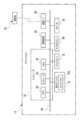
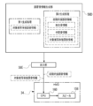
- FIG. 5 is a block diagram for explaining an example of processing contents of a sound collecting device side information acquisition unit, a target subject position information acquisition unit, a specific unit, and an adjustment sound information generation unit of the information processing device according to the embodiment.
- CPU refers to the abbreviation of "Central Processing Unit”.
- RAM is an abbreviation for "Random Access Memory”.
- DRAM refers to the abbreviation of "Dynamic Random Access Memory”.
- SRAM refers to the abbreviation of "Static Random Access Memory”.
- ROM is an abbreviation for "Read Only Memory”.
- SSD is an abbreviation for "Solid State Drive”.
- HDD refers to the abbreviation of "Hard Disk Drive”.
- EEPROM refers to the abbreviation of "Electrically Erasable and Programmable Read Only Memory”.
- I / F refers to the abbreviation of "Interface”.
- IC refers to the abbreviation of "Integrated Circuit”.
- ASIC refers to the abbreviation of "Application Special Integrated Circuit”.
- PLD refers to the abbreviation of "Programmable Logical Device”.
- FPGA refers to the abbreviation of "Field-Programmable Gate Array”.
- SoC refers to the abbreviation of "System-on-a-chip”.
- CMOS is an abbreviation for "Complementary Metal Oxide Semiconducor”.
- CCD refers to the abbreviation of "Charge Coupled Device”.
- EL refers to the abbreviation for "Electro-Luminescence”.
- GPU refers to the abbreviation of "Graphics Processing Unit”.
- LAN refers to the abbreviation of "Local Area Network”.
- 3D refers to the abbreviation of "3 Dimension”.
- USB refers to the abbreviation of "Universal Serial Bus”.
- HMD refers to the abbreviation of "Head Mounted Display”.
- fps refers to an abbreviation for "frame per second”.
- GPS is an abbreviation for "Global Positioning System”.
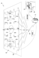
- the information processing system 10 includes an information processing device 12, a smartphone 14, a plurality of imaging devices 16, an imaging device 18, and a wireless communication base station (hereinafter, simply referred to as a “base station”) 20. And HMD34.
- the number of base stations 20 is not limited to one, and a plurality of base stations 20 may exist.
- the communication standards used in the base station 20 include a wireless communication standard including an LTE (Long Term Evolution) standard and a wireless communication standard including a WiFi (802.11) standard and / or a Bluetooth (registered trademark) standard. Is included.
- the imaging devices 16 and 18 are imaging devices having a CMOS image sensor, and are equipped with an optical zoom function and / or a digital zoom function. Instead of the CMOS image sensor, another type of image sensor such as a CCD image sensor may be adopted.
- CMOS image sensor another type of image sensor such as a CCD image sensor may be adopted.
- plural of image pickup devices when it is not necessary to distinguish between the image pickup device 18 and the plurality of image pickup devices 16, they are referred to as “plurality of image pickup devices” without reference numerals.
- the plurality of imaging devices 16 are installed in the soccer stadium 22. Each of the plurality of imaging devices 16 is arranged so as to surround the soccer field 24, and images are taken from a plurality of directions with a region including the soccer field 24 as an imaging region.
- an example in which each of the plurality of image pickup devices 16 is arranged so as to surround the soccer field 24 is given, but the technique of the present disclosure is not limited to this, and the arrangement of the plurality of image pickup devices 16 is not limited to this. It is determined according to the virtual viewpoint image to be generated.
- a plurality of image pickup devices 16 may be arranged so as to surround the entire soccer field 24, or a plurality of image pickup devices 16 may be arranged so as to surround a specific part thereof.
- the image pickup device 18 is installed in an unmanned aerial vehicle (for example, a multi-rotorcraft unmanned aerial vehicle), and takes a bird's-eye view of a region including a soccer field 24 as an imaging region from the sky.
- the imaging region in a state in which the region including the soccer field 24 is viewed from the sky refers to the imaging surface of the soccer field 24 by the imaging device 18.
- the information processing device 12 is installed in the control room 32.
- the plurality of imaging devices 16 and the information processing device 12 are connected via a LAN cable 30, and the information processing device 12 controls the plurality of imaging devices 16 and is imaged by each of the plurality of imaging devices 16. The image obtained by this is acquired.
- the connection using the wired communication method by the LAN cable 30 is illustrated here, the connection is not limited to this, and the connection using the wireless communication method may be used.
- the base station 20 transmits and receives various information to and from the information processing device 12, the smartphone 14, the HMD 34, and the unmanned aerial vehicle 27 via wireless communication. That is, the information processing device 12 is wirelessly connected to the smartphone 14, the HMD 34, and the unmanned aerial vehicle 27 via the base station 20.
- the information processing device 12 controls the unmanned aerial vehicle 27 by wirelessly communicating with the unmanned aerial vehicle 27 via the base station 20, and acquires an image obtained by being imaged by the imaging device 18 from the unmanned aerial vehicle 27. Or do.
- the information processing device 12 is a device corresponding to a server, and the smartphone 14 and the HMD 34 are devices corresponding to a client terminal for the information processing device 12.
- terminal devices when it is not necessary to distinguish between the smartphone 14 and the HMD 34, they are referred to as “terminal devices” without reference numerals.
- the information processing device 12 and the terminal device wirelessly communicate with each other via the base station 20, so that the terminal device requests the information processing device 12 to provide various services, and the information processing device 12 is the terminal device. Provide services to the terminal device in response to the request from.
- the information processing device 12 acquires a plurality of images from the plurality of imaging devices, and transmits the video generated based on the acquired plurality of images to the terminal device via the base station 20.
- the viewer 28 possesses a smartphone 14, and the HMD 34 is attached to the head of the viewer 28.
- the video transmitted from the information processing device 12 (hereinafter, also referred to as “delivered video”) is received by the terminal device, and the delivered video received by the terminal device is visually recognized by the viewer 28 through the terminal device.
- the soccer stadium 22 is provided with spectator seats 26 so as to surround the soccer field 24.
- the viewer 28 may visually recognize the delivered video at the spectator seat 26, or may visually recognize the delivered video at a place other than the spectator seat 26 (for example, at home, etc.), and the viewer 28 visually recognizes the delivered video.
- the location may be any location as long as it can wirelessly communicate with the information processing device 12.
- the viewer 28 is an example of a "person" according to the technique of the present disclosure.
- the HMD 34 includes a main body portion 11A, a mounting portion 13A, and a speaker 158.
- the HMD 34 is attached to the viewer 28.
- the main body 11A is located from the forehead to the front of the viewer 28, and the attachment portion 13A is located in the upper half of the head of the viewer 28.
- the speaker 158 is attached to the mounting portion 13A and is located on the left side of the viewer 28.
- the mounting portion 13A is a band-shaped member having a width of about several centimeters, and includes an inner ring 13A1 and an outer ring 15A1.
- the inner ring 13A1 is formed in an annular shape and is fixed in close contact with the upper half of the head of the viewer 28.
- the outer ring 15A1 is formed in a shape in which the occipital side of the viewer 28 is cut out. The outer ring 15A1 bends outward from the initial position or shrinks inward from the bent state toward the initial position according to the adjustment of the size of the inner ring 13A1.
- the main body 11A includes a protective frame 11A1, a computer 150, and a display 156.
- the computer 150 controls the entire HMD 34.
- the protective frame 11A1 is a transparent plate curved so as to cover the entire eyes of the viewer 28, and is formed of, for example, a translucent plastic.
- the display 156 includes a screen 156A and a projection unit 156B, and the projection unit 156B is controlled by the computer 150.
- the screen 156A is arranged inside the protective frame 11A1. Screen 156A is assigned to each of the eyes of viewer 28.
- the screen 156A is made of a transparent material like the protective frame 11A1. The viewer 28 visually recognizes the real space through the screen 156A and the protective frame 11A1. That is, the HMD 34 is a transmissive HMD.
- the screen 156A is located at a position facing the eyes of the viewer 28, and the distribution image is projected on the inner surface of the screen 156A (the surface on the viewer 28 side) by the projection unit 156B under the control of the computer 150. Since the projection unit 156B is a well-known device, detailed description thereof will be omitted, but a display element such as a liquid crystal display for displaying the distribution image and projection optics for projecting the distribution image displayed on the display element toward the inner surface of the screen 156A. A device having a system.
- the screen 156A is realized by using a half mirror that reflects the delivered image projected by the projection unit 156B and transmits the light in the real space.
- the projection unit 156B projects the delivered image on the inner surface of the screen 156A at a predetermined frame rate (for example, 60 fps).
- the delivered video is reflected on the inner surface of the screen 156A and is incident on the eyes of the viewer 28. As a result, the viewer 28 visually recognizes the delivered video.
- the half mirror is illustrated here as the screen 156A, the present invention is not limited to this, and the screen 156A itself may be used as a display element such as a liquid crystal.
- a retinal projection HMD that directly irradiates the retina of the viewer 28's eye with a laser may be adopted.
- the speaker 158 is connected to the computer 150 and outputs sound under the control of the computer 150. That is, under the control of the computer 150, the speaker 158 receives an electric signal indicating sound, converts the received electric signal into sound, and outputs the converted sound to display various information in an audible manner. Realize.
- the speaker 158 is integrated with the computer 150, but a separate headphone (including earphone) connected to the computer 150 by wire or wirelessly may be used to output sound.
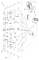
- the information processing apparatus 12 acquires a bird's-eye view image 46A showing an area including a soccer field 24 when observed from the sky from an unmanned aerial vehicle 27.
- the bird's-eye view image 46A is a moving image obtained by capturing a bird's-eye view of an area including a soccer field 24 as an imaging area (hereinafter, also simply referred to as an “imaging area”) by the imaging device 18 of the unmanned aerial vehicle 27. It is a statue.
- the captured image 46A is not limited to this, and is a still image showing a region including a soccer field 24 when observed from the sky. May be good.
- the information processing device 12 acquires a captured image 46B indicating an imaging region when observed from each position of the plurality of imaging devices 16 from each of the plurality of imaging devices 16.
- the captured image 46B is a moving image obtained by capturing an imaging region from a plurality of directions by each of the plurality of imaging devices 16.
- the captured image 46B is not limited to this, and the captured image 46B is a still image showing an imaging region when observed from each position of a plurality of imaging devices 16. It may be.
- the bird's-eye view image 46A and the captured image 46B are images obtained by capturing images in a plurality of directions in which regions including the soccer field 24 are different from each other, and are examples of "a plurality of images" according to the technique of the present disclosure.
- the information processing device 12 generates a virtual viewpoint image 46 by using the bird's-eye view image 46A and the captured image 46B.
- the virtual viewpoint image 46 is an image showing an imaging region when the imaging region is observed from a viewpoint position and a line-of-sight direction different from the viewpoint position and the line-of-sight direction of each of the plurality of imaging devices.
- the virtual viewpoint image 46 refers to a virtual viewpoint image showing an imaging area when the imaging area is observed from the viewpoint position 42 and the line-of-sight direction 44 in the spectator seat 26.
- An example of the virtual viewpoint image 46 is a moving image using a 3D polygon.
- a moving image is illustrated as the virtual viewpoint image 46, but the present invention is not limited to this, and a still image using 3D polygons may be used.
- the bird's-eye view image 46A obtained by being imaged by the image pickup apparatus 18 also shows a form example used for generating the virtual viewpoint image 46, but the technique of the present disclosure is not limited to this.
- the bird's-eye view image 46A is not used to generate the virtual viewpoint image 46, but only the plurality of captured images 46B obtained by being imaged by each of the plurality of imaging devices 16 are used to generate the virtual viewpoint image 46. You may do so.
- the virtual viewpoint image 46 is generated only from the image obtained by being imaged by the plurality of image pickup devices 16 without using the image obtained from the image pickup device 18 (for example, a multi-rotorcraft unmanned aerial vehicle). You may do so. If an image obtained from the image pickup device 18 (for example, a multi-rotorcraft unmanned aerial vehicle) is used, a more accurate virtual viewpoint image can be generated.
- the image pickup device 18 for example, a multi-rotorcraft unmanned aerial vehicle
- the information processing device 12 selectively transmits the bird's-eye view video 46A, the captured video 46B, and the virtual viewpoint video 46 as the distribution video to the terminal device.
- the information processing system 10 includes a plurality of sound collecting devices 100.
- the sound collecting device 100 collects sound.
- sound collection refers to sound capture, that is, sound collection.
- the sound collecting device 100 transmits sound information indicating the captured sound, that is, the collected sound.
- the plurality of sound collecting devices 100 exist in the imaging region, and the installation positions of the plurality of sound collecting devices 100 are fixed in the imaging region.
- "existence" refers to, for example, existence in a state of being spaced in a regular arrangement.
- the meaning of "existence” in the technique of the present disclosure also includes the meaning of existence in a state of being scattered irregularly or regularly.
- a plurality of sound collecting devices 100 are scattered in the imaging region, but the plurality of sound collecting devices 100 do not necessarily have to be scattered in the imaging region, for example, without gaps. It may be aligned. Further, the plurality of sound collecting devices 100 do not necessarily exist in the imaging region.
- the plurality of sound collecting devices 100 are provided in the imaging region by a highly directional microphone from the outside of the imaging region. Sound may be picked up.
- sound is picked up by a plurality of sound collecting devices 100 existing in the imaging region and a plurality of sound collecting devices 100 existing outside the imaging region.
- the sound collecting device 100 does not exist in the imaging region, and a plurality of sound collecting devices 100C exist outside the imaging region, and a plurality of sound collecting devices having directivity in the imaging region. Sound is picked up in the imaging region by the device 100.
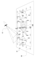
- the plurality of sound collecting devices 100 are embedded in the soccer field 24 in a matrix. Specifically, the sound collecting devices 100 are arranged at predetermined intervals (for example, at intervals of 5 meters) from one end to the other end of the side line and from one end to the other end of the goal line. In the example shown in FIG. 4A, 35 sound collecting devices 100 are arranged in a matrix in the soccer field 24, but the number of sound collecting devices 100 is not limited to this, and may be a plurality. Further, the plurality of sound collecting devices 100 do not need to be arranged in a matrix. For example, the plurality of sound collecting devices 100 may be arranged in a concentric circle, a spiral shape, or the like, and may be present in the soccer field 24.
- the plurality of sound collecting devices 100 are wirelessly connected to the information processing device 12 via the base station 20. Each of the plurality of sound collecting devices 100 exchanges various information with and from the information processing device 12 by performing wireless communication with the information processing device 12 via the base station 20. For example, each of the plurality of sound collecting devices 100 transmits sound information to the information processing device 12 in response to a request from the information processing device 12.
- the information processing device 12 generates adjustment sound information based on a plurality of sound information transmitted from the plurality of sound collecting devices 100.
- the adjusted sound information is information indicating the adjusted sound obtained by adjusting at least a part of the plurality of sounds indicated by the plurality of sound information.
- the information processing device 12 transmits the generated and obtained adjustment sound information to the HMD 34.
- the HMD 34 receives the adjustment sound information transmitted from the information processing apparatus 12, and outputs the adjustment sound indicated by the received adjustment sound information from the speaker 158.
- the information processing apparatus 12 includes a computer 50, a reception device 52, a display 53, a first communication I / F 54, and a second communication I / F 56.
- the computer 50 includes a CPU 58, a storage 60, and a memory 62, and the CPU 58, the storage 60, and the memory 62 are connected to each other via a bus line 64.
- a bus line 64 In the example shown in FIG. 5, for convenience of illustration, one bus line is shown as the bus line 64, but the bus line 64 includes a data bus, an address bus, a control bus, and the like.
- the CPU 58 controls the entire information processing device 12.
- the storage 60 stores various parameters and various programs.
- the storage 60 is a non-volatile storage device.
- a flash memory is adopted as an example of the storage 60, but the present invention is not limited to this, and may be EEPROM, HDD, SSD, or the like.
- the memory 62 is a volatile storage device. Various information is temporarily stored in the memory 62.
- the memory 62 is used as a work memory by the CPU 58.
- RAM is adopted as an example of the memory 62, but the present invention is not limited to this, and other types of volatile storage devices may be used.
- the reception device 52 receives instructions from the user or the like of the information processing device 12. Examples of the reception device 52 include a touch panel, hard keys, a mouse, and the like.
- the reception device 52 is connected to the bus line 64, and the instruction received by the reception device 52 is acquired by the CPU 58.
- the display 53 is connected to the bus line 64 and displays various information under the control of the CPU 58.
- An example of the display 53 is a liquid crystal display.
- another type of display such as an organic EL display or an inorganic EL display may be adopted as the display 53.
- the first communication I / F 54 is connected to the LAN cable 30.
- the first communication I / F 54 is realized by, for example, a device composed of circuits (for example, ASIC, FPGA, and / or PLD, etc.).
- the first communication I / F 54 is connected to the bus line 64 and controls the exchange of various information between the CPU 58 and the plurality of image pickup devices 16.
- the first communication I / F 54 controls a plurality of image pickup devices 16 according to the request of the CPU 58.
- the first communication I / F 54 acquires the captured image 46B (see FIG. 3) obtained by being imaged by each of the plurality of imaging devices 16, and outputs the acquired captured image 46B to the CPU 58.
- the second communication I / F 56 is connected to the base station 20 so as to be capable of wireless communication.
- the second communication I / F56 is realized by, for example, a device composed of circuits (for example, ASIC, FPGA, and / or PLD, etc.).
- the second communication I / F 56 is connected to the bus line 64.
- the second communication I / F 56 manages the exchange of various information between the CPU 58 and the unmanned aerial vehicle 27 in a wireless communication system via the base station 20. Further, the second communication I / F 56 manages the exchange of various information between the CPU 58 and the smartphone 14 in a wireless communication system via the base station 20.
- the second communication I / F 56 manages the exchange of various information between the CPU 58 and the HMD 34 in a wireless communication system via the base station 20. Further, the second communication I / F 56 manages the exchange of various information between the CPU 58 and each of the plurality of sound collecting devices 100 in a wireless communication system via the base station 20.
- the smartphone 14 includes a computer 70, a reception device 76, a display 78, a microphone 80, a speaker 82, an image pickup device 84, and a communication I / F 86.
- the computer 70 includes a CPU 88, a storage 90, and a memory 92, and the CPU 88, the storage 90, and the memory 92 are connected to each other via a bus line 94.
- one bus line is shown as the bus line 94 for convenience of illustration, but the bus line 94 may be composed of a serial bus, or may be a data bus, an address bus, and a bus line 94. It is configured to include a control bus and the like. Further, in the example shown in FIG.
- the CPU 88, the reception device 76, the display 78, the microphone 80, the speaker 82, the image pickup device 84, and the communication I / F86 are connected by a common bus, but the CPU 88 and each device are connected. It may be connected by a dedicated bus or a dedicated communication line.
- the CPU 88 controls the entire smartphone 14.
- the storage 90 stores various parameters and various programs.
- the storage 90 is a non-volatile storage device.
- EEPROM is adopted as an example of the storage 90, but the present invention is not limited to this, and a mask ROM, HDD, SSD, or the like may be used.
- Various information is temporarily stored in the memory 92, and the memory 92 is used as a work memory by the CPU 88.
- DRAM is adopted as an example of the memory 92, but the present invention is not limited to this, and other types of storage devices such as SRAM may be used.
- the reception device 76 receives instructions from the viewer 28. Examples of the reception device 76 include a touch panel 76A, a hard key, and the like. The reception device 76 is connected to the bus line 94, and the instruction received by the reception device 76 is acquired by the CPU 88.
- the display 78 is connected to the bus line 94 and displays various information under the control of the CPU 88.
- An example of the display 78 is a liquid crystal display.
- another type of display such as an organic EL display may be adopted as the display 78.
- the smartphone 14 is provided with a touch panel display, and the touch panel display is realized by the touch panel 76A and the display 78. That is, the touch panel display is formed by superimposing the touch panel 76A on the display area of the display 78. Further, in the present embodiment, the touch panel 28 is provided independently, but it may be built in the display 76A (so-called in-cell type touch panel).
- the microphone 80 collects sound (collects sound) and converts the collected sound into an electric signal.
- the microphone 80 is connected to the bus line 94.
- the electric signal obtained by converting the sound collected by the microphone 80 is acquired by the CPU 88 via the bus line 94.
- the speaker 82 converts an electric signal into sound.
- the speaker 82 is connected to the bus line 94.
- the speaker 82 receives the electric signal output from the CPU 88 via the bus line 94, converts the received electric signal into sound, and outputs the sound obtained by converting the electric signal to the outside of the smartphone 14.
- the image pickup device 84 acquires an image showing the subject by taking an image of the subject.
- the image pickup apparatus 84 is connected to the bus line 94.
- the image obtained by capturing the subject by the image pickup apparatus 84 is acquired by the CPU 88 via the bus line 94.
- the communication I / F86 is connected to the base station 20 so as to be capable of wireless communication.
- Communication I / F86 is realized, for example, by a device composed of circuits (eg, ASIC, FPGA, and / or PLD, etc.).
- the communication I / F86 is connected to the bus line 94.
- the communication I / F86 manages the exchange of various information between the CPU 88 and the external device in a wireless communication system via the base station 20.
- examples of the "external device" include an information processing device 12, an unmanned aerial vehicle 27, and an HMD 34.
- the HMD 34 is an example of a “display device” according to the technology of the present disclosure, and includes a computer 150, a reception device 152, a display 156, a microphone 157, a speaker 158, an eye tracker 166, and a communication I /. It is equipped with F168.
- the computer 150 includes a CPU 160, a storage 162, and a memory 164, and the CPU 160, the storage 162, and the memory 164 are connected via a bus line 170.
- a bus line 170 In the example shown in FIG. 7, one bus line is shown as the bus line 170 for convenience of illustration, but the bus line 170 includes a data bus, an address bus, a control bus, and the like.
- the CPU 160 controls the entire HMD 34.
- the storage 162 stores various parameters and various programs.
- the storage 162 is a non-volatile storage device.
- EEPROM is adopted as an example of the storage 162, but the present invention is not limited to this, and a mask ROM, HDD, SSD, or the like may be used.
- the memory 164 is a volatile storage device. Various information is temporarily stored in the memory 164, and the memory 164 is used as a work memory by the CPU 160.
- DRAM is adopted as an example of the memory 164, but the present invention is not limited to this, and other types of volatile storage devices such as SRAM may be used.
- the reception device 152 receives instructions from the viewer 28. Examples of the receiving device 152 include a remote controller and / or a hard key.
- the reception device 152 is connected to the bus line 170, and the instruction received by the reception device 152 is acquired by the CPU 160.
- the display 156 is a display capable of displaying the distribution video visually recognized by the viewer 28.
- the display 156 is connected to the bus line 170 and displays various information under the control of the CPU 160.
- the microphone 157 collects sound (collects sound) and converts the collected sound into sound information which is an electric signal.
- the microphone 157 is connected to the bus line 170.
- the sound information obtained by converting the sound collected by the microphone 157 is acquired by the CPU 160 via the bus line 170.
- the speaker 158 converts an electric signal into sound.
- the speaker 158 is connected to the bus line 170.
- the speaker 158 receives the electric signal output from the CPU 160 via the bus line 170, converts the received electric signal into sound, and outputs the sound obtained by converting the electric signal to the outside of the HMD 34.
- the eye tracker 166 includes an image sensor 166A.
- a CMOS image is adopted as the image sensor 166A.
- the image sensor 166A is not limited to the CMOS image sensor, and may be another type of image sensor such as a CCD image sensor.
- the eye tracker 166 uses the image sensor 166A to image both eyes of the viewer 28 according to a predetermined frame rate (for example, 60 fps).
- the eye tracker is based on an eye image (an image showing the eyes of the viewer 28) obtained by imaging both eyes of the viewer 28, and is also referred to as a line-of-sight direction of the viewer 28 (hereinafter, also simply referred to as “line-of-sight direction”). ) Is detected.
- the eye tracker 166 is a target subject image (hereinafter, also simply referred to as “target subject image”) indicating the target subject in the distributed video in a state where the distributed video (for example, the virtual viewpoint image 46) is displayed on the display 156.
- target subject image As the observation direction (hereinafter, also simply referred to as “observation direction”) of the viewer 28 who is observing the image, the line-of-sight direction is detected based on the image obtained by being imaged by the image sensor 166A.
- observation direction hereinafter, also simply referred to as “observation direction” of the viewer 28 who is observing the image
- the eye tracker 166 is an example of a "detector" according to the technique of the present disclosure.
- the communication I / F 168 is connected to the base station 20 so as to be capable of wireless communication.
- Communication I / F168 is realized, for example, by a device composed of circuits (eg, ASIC, FPGA, and / or PLD, etc.).
- the communication I / F 168 is connected to the bus line 170.
- the communication I / F 168 controls the exchange of various information between the CPU 160 and the external device in a wireless communication system via the base station 20.
- Examples of the "external device” include an information processing device 12, an unmanned aerial vehicle 27, a smartphone 14, and the like.
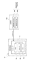
- the sound collecting device 100 includes a computer 200, a microphone 207, and a communication I / F 218.
- the computer 200 includes a CPU 210, a storage 212, and a memory 214, and the CPU 210, the storage 212, and the memory 214 are connected via a bus line 220.
- one bus line is shown as the bus line 220 for convenience of illustration, but the bus line 220 includes a data bus, an address bus, a control bus, and the like.
- the CPU 210 controls the entire sound collecting device 100.
- the storage 212 stores various parameters and various programs.
- the storage 212 is a non-volatile storage device.
- EEPROM is adopted as an example of the storage 212, but the present invention is not limited to this, and a mask ROM, HDD, SSD, or the like may be used.
- the memory 214 is a volatile storage device. Various types of information are temporarily stored in the memory 214, and the memory 214 is used as a work memory by the CPU 210.
- DRAM is adopted as an example of the memory 214, but the present invention is not limited to this, and other types of volatile storage devices such as SRAM may be used.
- the microphone 207 collects sound (collects sound) and converts the collected sound into an electric signal.
- the microphone 207 is connected to the bus line 220.
- the electric signal obtained by converting the sound collected by the microphone 207 is acquired by the CPU 210 via the bus line 220.
- the communication I / F 218 is connected to the base station 20 so as to be capable of wireless communication.
- Communication I / F218 is realized by, for example, a device composed of circuits (ASIC, FPGA, and / or PLD, etc.).
- the communication I / F 218 is connected to the bus line 220.
- the communication I / F 218 manages the exchange of various information between the CPU 210 and the information processing device 12 in a wireless communication system via the base station 20.
- the video generation program 60A and the sound generation program 60B are stored in the storage 60.
- information processing device programs when it is not necessary to distinguish between the video generation program 60A and the sound generation program 60B, they are referred to as "information processing device programs" without reference numerals.
- the CPU 58 is an example of the "processor” according to the technology of the present disclosure
- the memory 62 is an example of the “memory” according to the technology of the present disclosure.
- the CPU 58 reads the information processing device program from the storage 60, and expands the read information processing device program into the memory 62.
- the CPU 58 controls the entire information processing device 12 according to the information processing device program developed in the memory 62, and various information is provided between the plurality of imaging devices, the unmanned aerial vehicle 27, the terminal device, and the plurality of sound collecting devices 100. To give and receive.
- the CPU 58 reads the video generation program 60A from the storage 60, and expands the read video generation program 60A into the memory 62.
- the CPU 58 operates as the video generation unit 58A and the acquisition unit 58B according to the video generation program 60A expanded in the memory 62.
- the CPU 58 operates as the video generation unit 58A and the acquisition unit 58B to execute the video generation process (see FIG. 20) described later.
- the CPU 58 reads the sound generation program 60B from the storage 60, and expands the read sound generation program 60B into the memory 62.
- the CPU 58 operates as the acquisition unit 58B, the specific unit 58C, the adjustment sound information generation unit 58D, and the output unit 58E according to the sound generation program 60B expanded in the memory 62.
- the CPU 58 operates as an acquisition unit 58B, a specific unit 58C, an adjustment sound information generation unit 58D, and an output unit 58E to execute a sound generation process (see FIGS. 21 and 22) described later.
- the controlled sound information generation unit 58D is an example of the "generation unit" according to the technique of the present disclosure.
- the information processing device 12 transmits the bird's-eye view image 46A to the smartphone 14.
- the smartphone 14 receives the bird's-eye view image 46A transmitted from the information processing device 12.
- the bird's-eye view image 46A received by the smartphone 14 is displayed on the display 78 of the smartphone 14.
- the viewpoint instruction refers to an instruction of the position of a virtual viewpoint (hereinafter, referred to as “virtual viewpoint”) with respect to the imaging region.
- the line-of-sight instruction refers to an instruction in the direction of a virtual line-of-sight (hereinafter, referred to as “virtual line-of-sight”) with respect to the imaging region.
- the angle of view instruction refers to an instruction of the angle of view (hereinafter, simply referred to as “angle of view”) with respect to the imaging region.
- view-point line-of-sight angle-of-view instruction The position of the virtual viewpoint is also referred to as a “virtual viewpoint position”. Further, the direction of the "virtual line of sight” is also referred to as the "virtual line of sight direction”.
- a touch operation on the touch panel 76A can be mentioned. Instead of the touch operation, a tap operation or a double tap operation may be performed.
- Examples of the line-of-sight instruction include a slide operation on the touch panel 76A. Instead of the slide operation, a flick operation may be performed.
- Examples of the angle of view instruction include a pinch operation on the touch panel 76A. The pinch operation is roughly divided into a pinch-in operation and a pinch-out operation. The pinch-in operation is an operation performed when the angle of view is widened, and the pinch-out operation is an operation performed when the angle of view is narrowed.
- the viewpoint information indicating the virtual viewpoint position indicated by the viewpoint instruction, the line-of-sight direction information indicating the virtual line-of-sight direction instructed by the line-of-sight instruction, and the angle-of-view information indicating the angle of view indicated by the angle-of-view instruction are provided by the CPU 88 of the smartphone 14. It is transmitted to the information processing device 12.
- the term “view-view line-of-sight angle-of-view information” is used.
- the viewpoint line-of-sight angle of view information transmitted by the CPU 88 of the smartphone 14 is received by the image generation unit 58A, and the angle of view information transmitted by the CPU 88 of the smartphone 14 is received by the adjustment sound information generation unit 58D.
- the image generation unit 58A acquires the bird's-eye view image 46A from the unmanned aerial vehicle 27, and acquires the captured image 46B from each of the plurality of imaging devices 16.
- the first position association information is added to the bird's-eye view image 46A, and the second position association information is added to the captured image 46B.
- the first position association information is information indicating the correspondence between the position in the imaging region and the position in the bird's-eye view image 46A (for example, the position of the pixel).
- the position identification information in the imaging region for example, three-dimensional coordinates
- the position identification information in the bird's-eye view image that can specify the position in the bird's-eye view image 46A are provided. It is associated.
- the imaging region is a rectangular parallelepiped three-dimensional region with the soccer field 24 as the bottom surface, and the position identification information in the imaging region is one of the four corners of the soccer field 24. Is expressed in three-dimensional coordinates with the origin 24A as the origin.
- the second position association information is information indicating the correspondence between the position in the imaging region and the position of the captured image 46B (for example, the position of the pixel).
- the position identification information in the imaging region for example, three-dimensional coordinates
- the position identification information in the imaging image that can identify the position in the imaging image 46B are provided. It is associated.
- the image generation unit 58A generates a virtual viewpoint image 46 by using the bird's-eye view image 46A acquired from the unmanned aerial vehicle 27 and the captured image 46B acquired from each of the plurality of imaging devices 16 based on the line-of-sight angle of view information. ..
- Third position association information is added to the virtual viewpoint image 46.
- the third position association information is information indicating the correspondence relationship between the position in the imaging region and the position in the virtual viewpoint image 46 (for example, the position of the pixel), and is the information indicating the correspondence relationship of the "correspondence relationship information" according to the technique of the present disclosure. This is an example.
- the third position association information is generated by the video generation unit 58A based on the first position association information and the second position association information.
- the third position association information is an example of the "correspondence relationship information" related to the technique of the present disclosure, but in the image generation unit 58A, the virtual viewpoint image 46 is generated.
- the first position association information is an example of "correspondence-related information" according to the technique of the present disclosure.
- the second position association information corresponds to the technique of the present disclosure. This is an example of "relationship information”.
- the image generation unit 58A regenerates the virtual viewpoint image 46 with the change of the viewpoint information and the line-of-sight direction information.
- the third position association information is also based on the first position association information and the second position association information. Is regenerated by the image generation unit 58A. Then, the regenerated third position association information is given to the latest virtual viewpoint image 46 by the image generation unit 58A.
- the image generation unit 58A regenerates the virtual viewpoint image 46 with the change of the angle of view information.
- the third position association information is also generated based on the first position association information and the second position association information. Regenerated by part 58A. Then, the regenerated third position association information is given to the latest virtual viewpoint image 46 by the image generation unit 58A.
- the image generation unit 58A transmits the virtual viewpoint image 46 and the third position association information to the HMD 34.
- the CPU 160 receives the virtual viewpoint image 46 and the third position association information transmitted from the image generation unit 58A, and displays the received virtual viewpoint image 46 on the display 156.
- the image sensor 166A images the eye portion 29 of the viewer 28 while the virtual viewpoint image 46 is displayed on the display 156.
- the eye tracker 166 detects the observation direction based on the eye image obtained by imaging the eye 29 by the image sensor 166A, and outputs the observation direction identification information capable of specifying the detected observation direction to the CPU 160.
- the CPU 160 is used by the viewer 28 on the display 156 (specifically, the screen 156A shown in FIG. 2) based on the observation direction identification information and the position identification information in the virtual viewpoint image included in the third position association information.
- the position of focus (hereinafter referred to as "focused position") is specified. Then, the CPU 160 derives the target subject position information based on the specified focus position and the third position association information.
- the target subject position information includes subject position information in the imaging region and subject position information in the virtual viewpoint image.
- the subject position information in the imaging region is information indicating the position of the target subject in the imaging region (hereinafter, also referred to as “target subject position”).
- target subject position is information that can specify the position of the target subject image 47 in the virtual viewpoint image 46 (hereinafter, also referred to as “target subject image position”) (for example, an address that can specify the pixel position).
- target subject position information is information in which the subject position information in the imaging region and the subject position information in the virtual viewpoint image are associated with each other in a state where the correspondence between the target subject position and the target subject image position can be specified.
- the CPU 160 derives the target subject position information based on the third position association information and the detection result by the eye tracker 166, that is, the observation direction identification information. Specifically, the CPU 160 acquires the position identification information in the imaging region and the position identification information in the virtual viewpoint image corresponding to the focus position as the target subject position information from the third position association information. The CPU 160 transmits the acquired target subject position information to the information processing device 12.
- the acquisition unit 58B includes a target subject position information acquisition unit 58B1.
- the target subject position information acquisition unit 58B1 acquires the target subject position information.
- the target subject position information transmitted from the CPU 160 of the HMD 34 is acquired by being received by the target subject position information acquisition unit 58B1.
- the target subject position information acquisition unit 58B1 outputs the target subject position information to the video generation unit 58A.
- the image generation unit 58A generates the virtual viewpoint image 46 by using the bird's-eye view image 46A and the captured image 46B based on the viewpoint line-of-sight angle of view information and the target subject position information described above.
- the image generation unit 58A focuses on the target subject image position specified by the position identification information in the virtual viewpoint image included in the target subject position information input from the target subject position information acquisition unit 58B1.
- the virtual viewpoint image 46 is generated.
- the image generation unit 58A generates a virtual viewpoint image 46 that is in focus with respect to the target subject image 47 rather than the image around the target subject image 47.
- the state in which the target subject image 47 is in focus more than the image around the target subject image 47 means that the contrast value of the target subject image 47 is higher than the contrast value of the image around the target subject image 47. Refers to a high state.
- the virtual viewpoint image 46 includes an in-focus area where the target subject image 47 is located and a peripheral area of the target subject image 47, and the contrast value is lower than the in-focus area. It is roughly divided into areas.
- the target subject image 47 is an example of the “virtual viewpoint target subject image” according to the technique of the present disclosure.
- the virtual viewpoint image 46 having the in-focus area and the out-of-focus area is transmitted to the HMD 34 by the image generation unit 58A with the third position association information added.
- the CPU 160 receives the virtual viewpoint video 46 and the third position association information transmitted from the video generation unit 58A.
- the CPU 160 displays the received virtual viewpoint image 46 on the display 156.
- the acquisition unit 58B includes a sound collecting device side information acquisition unit 58B2 in addition to the target subject position information acquisition unit 58B1.
- the target subject position information acquisition unit 58B1 outputs the target subject position identification information acquired from the HMD 34 to the specific unit 58C.
- the sound collecting device 100 transmits sound information and sound collecting position specifying information indicating the position of the sound collecting device 100 in the imaging region (hereinafter, also referred to as “sound collecting device position”) to the information processing device 12.
- sound collecting position specifying information three-dimensional coordinates capable of specifying the sound collecting device position in the imaging region are adopted.
- the sound collecting position specifying information is an example of "sound collecting device position information" according to the technique of the present disclosure.
- the sound collecting device side information acquisition unit 58B2 acquires sound information and sound collecting position specifying information.
- the sound information and the sound collecting position specifying information transmitted from the sound collecting device 100 are acquired by being received by the sound collecting device side information acquisition unit 58B2.
- the sound collecting device side information acquisition unit 58B2 generates sound collecting device information based on the sound information acquired from the sound collecting device 100 and the sound collecting position specifying information.
- the sound collecting device information is information in which sound information and sound collecting position specifying information are associated with each sound collecting device 100.
- the sound collecting device side information acquisition unit 58B2 outputs the generated sound collecting device information to the specific unit 58C.
- the specific unit 58C acquires the target subject position information from the target subject position information acquisition unit 58B1 and acquires the sound collection device information from the sound collection device side information acquisition unit 58B2. Then, the specifying unit 58C identifies the target sound in the region corresponding to the target subject from the plurality of sound information based on the target subject position information and the sound collecting device information.
- the specific unit 58C acquires sound collecting device information for each of the plurality of sound collecting devices 100 from the sound collecting device side information acquisition unit 58B2. That is, the specific unit 58C acquires a plurality of sound collecting device information from the sound collecting device side information acquisition unit 58B2.
- the specifying unit 58C identifies the sound collecting device information having the sound collecting position specifying information corresponding to the subject position information in the imaging region included in the target subject position information from the plurality of sound collecting device information.
- the sound collecting position specifying information corresponding to the subject position information in the imaging area is the imaging area among a plurality of sound collecting device positions indicated by the plurality of sound collecting position specifying information included in the plurality of sound collecting device information. It refers to the sound collecting position specifying information that can specify the sound collecting device position closest to the target subject position specified from the internal subject position information.
- the specifying unit 58C specifies the sound information included in the specified sound collecting device information as the target sound information indicating the target sound in the region corresponding to the target subject position.
- the adjustment sound information generation unit 58D acquires the target sound information specified by the specific unit 58C from the specific unit 58C, and obtains the sound pickup device information for each of the plurality of sound collection devices 100 from the sound collection device side information acquisition unit 58B2. get.
- the adjustment sound information generation unit 58D generates the adjustment sound information based on the acquired target sound information and the sound collecting device information.
- the adjusted sound information is roughly classified into comprehensive sound information and target subject emphasis sound information.
- Comprehensive sound information is an example of "comprehensive sound information” and "whole sound information” according to the technology of the present disclosure.
- Comprehensive sound information refers to information indicating comprehensive sound.
- Comprehensive sound is an example of "comprehensive sound” and "whole sound” according to the technique of the present disclosure.
- the total sound refers to a sound obtained by integrating a plurality of sounds obtained by each of the plurality of sound collecting devices 100.
- the target subject emphasis sound information refers to information indicating a sound (hereinafter, also referred to as "target subject emphasis sound”) including a target sound (hereinafter, also referred to as "emphatic target sound”) emphasized rather than an ambient sound.
- the ambient sound refers to a sound emitted from a region different from the region corresponding to the target subject position indicated by the subject position information in the imaging region included in the target subject position information acquired by the specific unit 58C.
- the area corresponding to the target subject position refers to, for example, the target subject itself.
- the area corresponding to the target subject position may be a three-dimensional area defined by a predetermined distance from the target subject position.
- a three-dimensional region defined by a predetermined distance from the target subject position for example, a spherical region within a radius of 3 meters centered on the target subject position, or a 4 meter square cube centered on the target subject position. The radial region is mentioned.
- the emphasis target sound makes the volume of the ambient sound lower than the volume of the sound indicated by the sound information related to the ambient sound, or makes the volume of the target sound louder than the volume of the target sound indicated by the target sound information. It is realized by. Not limited to this, the emphasis target sound makes the volume of the ambient sound lower than the volume of the sound indicated by the sound information related to the ambient sound, and the volume of the target sound is the target sound indicated by the target sound information. It may be realized by making it louder than the volume of.
- the controlled sound information generation unit 58D selectively executes the first generation process and the second generation process.
- the first generation process is a process for generating target subject emphasis sound information
- the second generation process is a process for generating comprehensive sound information.
- the adjusted sound information generation unit 58D selectively executes the first generation process and the second generation process based on the angle of view information acquired from the smartphone 14.
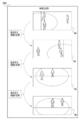
- the adjustment sound information generation unit 58D executes the first generation process when the angle of view indicated by the angle of view information is less than the reference angle of view, and the angle of view indicated by the angle of view information is The second generation process is executed when the angle of view is equal to or larger than the reference angle of view.
- the angle of view indicated by the angle of view information is “ ⁇ ” and the reference angle of view is “ ⁇ th ”
- “adjustment sound information is generated when the angle of view ⁇ ⁇ reference angle of view ⁇ th ”.
- the target subject emphasis sound information is generated by executing the first generation process by the unit 58D.
- the adjustment sound information generation unit 58D performs the second generation process. Comprehensive sound information is generated by executing.
- the target subject emphasis sound may cause discomfort to the viewer 28. Therefore, here, a sensory test is performed as a lower limit value of the angle of view that does not cause discomfort to the viewer 28 when the total sound is output from the speaker 158 than when the target subject emphasis sound is output from the speaker 158. And / or a fixed value derived in advance by computer simulation or the like is adopted as the reference angle of view ⁇ th .
- the reference angle theta th a modifiable variable value according to the instructions received by the receiving device 52, 76 or 152 May be adopted as.
- the CPU 58 (see FIG. 9) operates as an output unit 58E capable of outputting target subject emphasis sound information generated by the adjustment sound information generation unit 58D.
- the output unit 58E acquires the target subject emphasis sound information from the adjustment sound information generation unit 58D when the target subject emphasis sound information is generated by executing the first generation process, and the acquired target subject emphasis sound information. Is output. That is, the output unit 58E transmits the target subject emphasis sound information to the HMD 34. Further, when the total sound information is generated by executing the second generation process, the output unit 58E acquires the total sound information from the adjustment sound information generation unit 58D and outputs the acquired total sound information. That is, the output unit 58E transmits the comprehensive sound information to the HMD 34.
- the output unit 58E outputs the target subject emphasis sound information and the total sound information in synchronization with the output of the virtual viewpoint image 46 to the HMD 34 by the image generation unit 58A.
- the image generation unit 58A outputs the synchronization signal to the output unit 58E at the timing when the output of the virtual viewpoint image 46 is started.
- the output unit 58E outputs the target subject emphasis sound information and the total sound information in accordance with the input of the synchronization signal from the image generation unit 58A.
- the target subject emphasis sound information transmitted from the output unit 58E is received by the CPU 160, and the target subject emphasis sound indicated by the received target subject emphasis sound information is output from the speaker 158. Further, in the HMD 34, the total sound information transmitted from the output unit 58E is received by the CPU 160, and the total sound indicated by the received total sound information is output from the speaker 158.
- step ST10 the image generation unit 58A acquires the bird's-eye view image 46A, the captured image 46B, and the viewpoint line-of-sight angle of view information, and then the image generation process shifts to step ST12. ..
- step ST12 the image generation unit 58A uses the bird's-eye view image 46A and the captured image 46B acquired in step ST10 based on the viewpoint line-of-sight angle of view information acquired in step ST10, thereby focusing on a virtual viewpoint at infinity.
- the video 46 is generated, and then the video generation process proceeds to step ST14.
- step ST14 the video generation unit 58A outputs the virtual viewpoint video 46 generated in step ST12 to the HMD 34, and then the video generation process shifts to step ST16.
- the virtual viewpoint image 46 output to the HMD 34 by executing the process of step ST14 is displayed on the display 156 in the HMD 34 and is visually recognized by the viewer 28.
- step ST16 the target subject position information acquisition unit 58B1 acquires the target subject position information derived by the CPU 160 based on the detection result of the eye tracker 166, and then the image generation process shifts to step ST18.
- step ST18 the image generation unit 58A acquires the bird's-eye view image 46A, the captured image 46B, and the viewpoint line-of-sight angle of view information, and then the image generation process shifts to step ST20.
- step ST20 the image generation unit 58A uses the bird's-eye view image 46A and the captured image 46B acquired in step ST18 based on the viewpoint line-of-sight angle of view information acquired in step ST18 and the target subject position information acquired in step ST16. A virtual viewpoint image 46 that is in focus with respect to the target subject image 47 is generated, and then the image generation process proceeds to step ST22.
- step ST22 the video generation unit 58A outputs the virtual viewpoint video 46 generated in step ST20 to the HMD 34, and then the video generation process shifts to step ST24.
- the virtual viewpoint image 46 output to the HMD 34 by executing the process of step ST22 is displayed on the display 156 in the HMD 34 and is visually recognized by the viewer 28.
- step ST24 the CPU 58 determines whether or not the condition for ending the video generation process (video generation process end condition) is satisfied.
- the video generation processing end condition there is a condition that the reception device 52, 76 or 152 has received an instruction to end the video generation process. If the video generation processing end condition is not satisfied in step ST24, the determination is denied and the video generation processing proceeds to step ST16. If the video generation process end condition is satisfied in step ST24, the determination is affirmed and the video generation process ends.
- step ST50 the sound collecting device side information acquisition unit 58B2 acquires sound information and sound collecting position specifying information from each of the plurality of sound collecting devices 100, and then generates sound. The process proceeds to step ST52.
- step ST52 the sound collecting device side information acquisition unit 58B2 generates sound collecting device information for each of the plurality of sound collecting devices 100 based on the sound information and the sound collecting position specifying information acquired in step ST50, and then generates sound collecting device information. , The sound generation process proceeds to step ST54.
- step ST54 the adjustment sound information generation unit 58D acquires the angle of view information from the smartphone 14, and then the sound generation process shifts to step ST56.
- step ST56 the adjustment sound information generation unit 58D determines whether or not the angle of view indicated by the angle of view information acquired in step ST54 is less than the reference angle of view. In step ST56, if the angle of view indicated by the angle of view information acquired in step ST54 is equal to or greater than the reference angle of view, the determination is denied and the sound generation process proceeds to step ST58 shown in FIG. In step ST56, if the angle of view indicated by the angle of view information acquired in step ST54 is less than the reference angle of view, the determination is affirmed and the sound generation process proceeds to step ST64.
- step ST58 shown in FIG. 22 the adjustment sound information generation unit 58D generates comprehensive sound information based on the sound collecting device information generated in step ST52, and then the sound generation process shifts to step ST60.
- step ST60 the output unit 58E determines whether or not a synchronization signal has been input from the video generation unit 58A. If the synchronization signal is not input from the video generation unit 58A in step ST60, the determination is denied and the determination in step ST60 is performed again. When a synchronization signal is input from the video generation unit 58A in step ST60, the determination is affirmed, and the sound generation process proceeds to step ST62.
- step ST62 the output unit 58E outputs the total sound information generated in step ST58 to the HMD 34, and then the sound generation process shifts to step ST74 shown in FIG.
- the total sound indicated by the total sound information output to the HMD 34 by executing the process of step ST62 is output from the speaker 158 in the HMD 34 and heard by the viewer 28.
- step ST64 shown in FIG. 21 the target subject position information acquisition unit 58B1 acquires the target subject position information from the HMD 34, and then the sound generation process shifts to step ST66.
- step ST66 the specifying unit 58C identifies the target sound information based on the sound collecting device information generated in step ST52 and the target subject position information acquired in step ST64, and then the sound generation process is performed in step. Move to ST68.
- step ST68 the adjustment sound information generation unit 58D generates target subject emphasis sound information based on the sound collecting device information generated in step ST50 and the target sound information specified in step ST66, and then the sound. The generation process proceeds to step ST70.
- step ST70 the output unit 58E determines whether or not a synchronization signal has been input from the video generation unit 58A. If the synchronization signal is not input from the video generation unit 58A in step ST70, the determination is denied and the determination in step ST70 is performed again. When a synchronization signal is input from the video generation unit 58A in step ST70, the determination is affirmed, and the sound generation process shifts to step ST72.
- step ST72 the output unit 58E outputs the target subject emphasis sound information generated in step ST68 to the HMD34, and then the sound generation process shifts to step ST74.
- the target subject emphasis sound indicated by the target subject emphasis sound information output to the HMD 34 by executing the process of step ST72 is output from the speaker 158 in the HMD 34 and is heard by the viewer 28.
- step ST74 the CPU 58 determines whether or not the condition for ending the sound generation process (sound generation process end condition) is satisfied.
- the sound generation processing end condition there is a condition that the reception device 52, 76 or 152 has received an instruction to end the sound generation process. If the condition for ending the sound generation process is not satisfied in step ST74, the determination is denied and the sound generation process proceeds to step ST50. If the sound generation process end condition is satisfied in step ST74, the determination is affirmed and the sound generation process ends.
- the target subject position information acquisition unit 58B1 acquires the target subject position information from the HMD 34, and the sound collection device side information acquisition unit 58B2 obtains the sound information and the sound collection position identification information. Obtained from each of the plurality of sound collecting devices 100. Further, the specific unit 58C specifies the target sound in the region corresponding to the target subject position from the plurality of sound information based on the sound collection position identification information and the target subject position information. Then, when the virtual viewpoint image 46 is generated, the target subject emphasis sound information is generated by the adjustment sound information generation unit 58D.
- the target subject emphasis sound information is information indicating the target subject emphasis sound.
- the target subject emphasis sound emphasizes the target sound more than the sound (peripheral sound) emitted from an area different from the area corresponding to the target subject position indicated by the target subject position information acquired by the target subject position information acquisition unit 58B1. It is a sound including the emphasized sound to be emphasized. Therefore, it is possible to contribute to the hearing by the viewer 28 of the sound emitted from the region corresponding to the position of the target subject indicated by the generated virtual viewpoint image 46.
- the first generation process and the second generation process are selectively executed by the adjustment sound information generation unit 58D.
- the target subject emphasis sound information is generated
- the comprehensive sound information is generated. Therefore, the target subject emphasis sound information and the total sound information can be selectively generated.
- the first generation process is executed when the angle of view indicated by the angle of view information is less than the reference angle of view
- the second generation process is executed when the angle of view indicated by the angle of view information is equal to or greater than the reference angle of view. The generation process is executed. Therefore, the target subject emphasis sound information and the total sound information can be selectively generated according to the angle of view.
- the eye tracker 166 detects the observation direction of the viewer 28 who is observing the virtual viewpoint image 46 while the virtual viewpoint image 46 is displayed on the display 156 of the HMD 34.
- the CPU 160 generates the target subject position information based on the third position association information and the detection result of the eye tracker 166, and the generated target subject position information is acquired by the target subject position information acquisition unit 58B1. Will be done.
- the target subject position information acquired by the target subject position information acquisition unit 58B1 is used to identify the target sound information by the specific unit 58C, and the target sound information specified by the specific unit 58C is the target sound information generation unit 58D. Used to generate subject emphasis sound information. Therefore, it is possible to prevent the information indicating the sound emitted from the position irrelevant to the observation direction of the viewer 28 from being erroneously generated as the target subject emphasis sound information.
- the line-of-sight direction of the viewer 28 is detected as an observation direction by the eye tracker 166 based on the eye image obtained by imaging the eye portion 29 of the viewer 28 by the image sensor 166A.
- the observation direction can be detected with higher accuracy than when a direction different from the line-of-sight direction of the viewer 28 is detected as the observation direction.
- the HMD 34 is attached to the viewer 28, and the HMD 34 is provided with the eye tracker 166. Therefore, as compared with the case where the eye tracker 166 is not provided on the HMD 34, the observation direction in the state where the HMD 34 is attached to the viewer 28 can be detected with higher accuracy.
- the target subject image is an image in the virtual viewpoint image 46 that is more in focus than the image around the target subject image. Therefore, the position where the target subject emphasis sound is emitted can be specified from the virtual viewpoint image 46.
- the information processing device 12 a plurality of sound collecting devices 100 are fixed in the imaging region. Therefore, the sound collecting position specifying information can be easily acquired as compared with the case where the plurality of sound collecting devices 100 move.
- the target subject position information acquisition unit 58B1 has been described with reference to a form example in which the target subject position information is acquired based on the detection result of the eye tracker 166, but the technique of the present disclosure is not limited to this.
- the target subject position information may be acquired by the target subject position information acquisition unit 58B1 based on the instruction received by the reception device 52, 76 or 152.
- the distributed video here, as an example, the virtual viewpoint video 46
- the instruction information indicating the position of the target subject image in the distributed video is the reception device 52, 76 or 152. Accepted by.
- the target subject position information acquisition unit 58B1 acquires the target subject position information based on the third position association information and the instruction information received by the reception device 52, 76 or 152. That is, the target subject position information acquisition unit 58B1 derives the target subject position identification information in the imaging region corresponding to the target subject image position instructed by the instruction information as the target subject position information from the third position association information. Get location information.
- the reception device 52, 76 or 152 is an example of the "reception device (acceptor)" according to the technique of the present disclosure.
- the technique of the present disclosure is not limited to this.
- observation direction change frequency the frequency at which the observation direction of the viewer 28 changes per unit time
- the adjustment sound information generation unit 58D may selectively execute the first generation process and the second generation process according to the frequency of change in the observation direction.
- the CPU 160 is based on the observation direction identification information, as shown in FIG. 23 as an example.
- the frequency of change in the observation direction (for example, N times / sec) is calculated.
- the CPU 160 outputs observation direction change frequency information indicating the calculated frequency to the accommodation sound information generation unit 58D.
- the adjustment sound information generation unit 58D executes the first generation process or the second generation process with reference to the observation direction change frequency information.
- the second generation process is executed without executing the first generation process. Further, when the observation direction change frequency is less than the predetermined frequency, the first generation process is executed without executing the second generation process.
- the target subject emphasis sound is output from the speaker 158 when the observation direction is not determined, the target subject emphasis sound may cause discomfort to the viewer 28. Therefore, here, as the lower limit value of the observation direction change frequency in which the total sound is output from the speaker 158 rather than the target subject emphasis sound is output from the speaker 158, the viewer 28 is not uncomfortable. Fixed values derived in advance by sensory tests and / or computer simulations are adopted as the default frequency.
- a variable value that can be changed according to the instruction received by the receiving device 52, 76 or 152 may be adopted as the default frequency.
- the sound generation process executed by the CPU 160 is the sound shown in FIG. Compared with the generation process, it is different in that it has step ST100 instead of step ST54 and that it has step ST102 instead of step ST56.
- step ST100 the adjustment sound information generation unit 58D acquires the observation direction change frequency information from the HMD 34, and then the sound generation process shifts to step ST102.
- step ST102 the adjustment sound information generation unit 58D determines whether or not the observation direction change frequency indicated by the observation direction change frequency information acquired in step ST100 is less than the predetermined frequency. In step ST102, if the observation direction change frequency indicated by the observation direction change frequency information acquired in step ST100 is equal to or higher than the predetermined frequency, the determination is denied and the sound generation process proceeds to step ST58 shown in FIG. In step ST102, if the observation direction change frequency indicated by the observation direction change frequency information acquired in step ST100 is less than the predetermined frequency, the determination is affirmed and the sound generation process proceeds to step ST64.
- the discomfort given to the viewer 28 due to the frequent switching of the target subject emphasis sound is reduced as compared with the case where the target subject emphasis sound is also switched as the target subject is frequently changed. be able to.
- the sound generation process shifts to step ST58 shown in FIG. 22, but the technique of the present disclosure is not limited to this.
- the sound generation process may shift to step ST58 shown in FIG. ..
- the sound generation process shifts to step ST64, but the technique of the present disclosure is not limited to this.
- the sound generation process may shift to step ST58 shown in FIG. ..
- the technique of the present disclosure is not limited to this.
- the target subject emphasis sound information may be generated, and the generated target subject emphasis sound information may not be output by the output unit 58E.
- the target subject emphasis sound is not output from the speaker 158, the viewer is caused by the frequent switching of the target subject emphasis sound as compared with the case where the target subject emphasis sound is also switched as the target subject changes frequently. The discomfort given to 28 can be reduced.
- the target subject emphasis sound information when the angle of view indicated by the angle of view information is equal to or larger than the reference angle of view, the target subject emphasis sound information is not generated, but the technique of the present disclosure is not limited to this. ..
- the target subject emphasis sound information when the angle of view indicated by the angle of view information is equal to or greater than the reference angle of view, the target subject emphasis sound information may be generated, and the generated target subject emphasis sound information may not be output by the output unit 58E.
- the adjustment sound information generation unit 58D may generate stepwise emphasis sound information by executing the second generation process.
- the stepwise emphasis sound information is information including comprehensive sound information, intermediate sound information, and target subject emphasis sound information.
- the intermediate sound information is information indicating an intermediate sound in which the target subject sound is emphasized more than the total sound and suppressed more than the target subject emphasized sound.
- the output unit 58E uses the total sound information, the intermediate sound information, and the target subject emphasis sound information generated by the adjustment sound information generation unit 58D as the total sound information.
- the intermediate sound information and the target subject emphasis sound information are output to the HMD 34 in this order.
- the sound generation process executed by the CPU 58 has a step 150 instead of the step ST58 and a step 152 instead of the step ST62, as compared with the sound generation process shown in FIG. Is different.
- step ST150 shown in FIG. 26 the stepwise emphasis sound information is generated by the adjustment sound information generation unit 58D, and in step ST152, the stepwise emphasis sound information generated in step ST150 is output to the HMD 34 by the output unit 58E.
- the total sound information, the intermediate sound information, and the target subject emphasis sound information are output to the HMD 34 from the speaker 158 in the order of the total sound, the intermediate sound, and the target subject emphasis sound, and are heard by the viewer 28.
- the discomfort given to the viewer 28 due to the frequent switching of the target subject emphasis sound is reduced as compared with the case where the target subject emphasis sound is also switched as the target subject is frequently changed. be able to.
- the intermediate sound information may be information including a plurality of sound information subdivided so that the volume is gradually increased in a stepless or multi-step manner.
- the target subject emphasis sound information information indicating the emphasis sound including the emphasis target sound is adopted, but the target subject emphasis sound information includes the emphasis target sound and also includes the peripheral sound. It may be information indicating no sound. As a result, it is possible to contribute to easier listening of the target sound as compared with the case where the target subject emphasis sound information is information indicating a sound including peripheral sounds in addition to the emphasized target sound.
- HMD34 is exemplified, but the technique of the present disclosure is not limited to this.
- the target subject by the target subject position information acquisition unit 58B1 based on the detection result by the eye tracker 166 provided in the specific HMD34 among the plurality of HMD34s and the third position association information.
- the position information may be acquired.
- the HMD 34 is attached to each of the viewers 28A to 28Z (hereinafter, when it is not necessary to distinguish between them, they are simply referred to as “viewers” without reference numerals).
- the target subject position information acquisition unit 58B1 obtains the target subject position information based on the detection result by the eye tracker 166 provided in the HMD 34 mounted on any of the viewers 28A to 28Z and the third position association information. get. According to this configuration, it is possible to generate target subject emphasis sound information corresponding to a target subject of interest to a viewer wearing a specific HMD34 among a plurality of HMD34s.
- the sound collecting device 300 may be attached to the target subject 47A.
- the sound collecting device 300 includes a computer 302, a GPS receiver 304, a microphone 306, a communication I / F 308, and a bus line 316.
- the computer 302 includes a CPU 310, a storage 312, and a memory 314.
- one bus line is shown as the bus line 316 for convenience of illustration, but the bus line 316 is similar to the bus lines 64, 94 and 170 described in the above embodiment. Includes a data bus, an address bus, a control bus, and the like.
- the computer 302 corresponds to the computer 200 shown in FIG.
- the microphone 306 corresponds to the microphone 207 shown in FIG.
- the communication I / F 308 corresponds to the communication I / F 218 shown in FIG.
- the CPU 310 corresponds to the CPU 210 shown in FIG.
- the storage 312 corresponds to the storage 212 shown in FIG.
- the memory 314 corresponds to the memory 214 shown in FIG.
- the GPS receiver 304 receives radio waves from a plurality of GPS satellites (not shown) in response to an instruction from the CPU 310, and outputs reception result information indicating the reception result to the CPU 310.
- the CPU 310 calculates GPS information indicating latitude, longitude, and altitude based on the reception result information input from the GPS receiver 304.
- the CPU 310 wirelessly communicates with the information processing device 12 via the base station 20 to transmit the sound information obtained from the microphone 306 to the information processing device 12, and also uses GPS information as sound collection position identification information. It is transmitted to the processing device 12. As a result, the position of the target subject 47A in the imaging region, that is, the target subject position is specified by the information processing apparatus 12.
- GPS information is used as sound collecting position specifying information
- the technique of the present disclosure is not limited to this, and information capable of specifying the position of the sound collecting device 300 in the imaging region. Any information may be used as long as it is. Further, a plurality of sound collecting devices 300 may be attached to the target subject 47A.
- the target sound can be easily obtained as compared with the case where the sound collecting device 300 is not attached to the target subject 47A.
- the sound collecting device 300 may be attached to each of a plurality of persons (for example, a player and / or a referee in the soccer field 24) who can be a target subject existing in the imaging region. According to this configuration, it is possible to easily obtain the target sound even if the target subject is switched between the plurality of people, as compared with the case where the sound collecting device 300 is not attached to each of the plurality of people in the imaging region. it can.
- a plurality of sound collecting devices 300 are fixed in the imaging region as described above, but the sound collecting devices 300 and sound collecting devices attached to each of the plurality of persons have been described.
- the device 300 may be used in combination.
- the sound information obtained by the sound collecting device 100 is used by the information processing device 12 without changing the volume, but the technique of the present disclosure is not limited to this.
- the volume may be made different among a plurality of sounds indicated by the plurality of sound information obtained by the plurality of sound collecting devices 100.
- the specific unit 58C uses the sound collection position identification information acquired by the sound collection device side information acquisition unit 58B2 and the target subject position information acquired by the target subject position information acquisition unit 58B1 to obtain the target subject.
- the positional relationship between the position and the plurality of sound collecting devices 100 is specified.
- the adjustment sound information generation unit 58D adjusts the sound indicated by the sound information to be smaller as the sound at a position farther from the target subject position, as shown in FIG. 29 as an example, according to the positional relationship specified by the specific unit 58C.
- the sound information is controlled so that the sound is produced.
- the sound information controlled in this way is used, for example, by the adjustment sound information generation unit 58D to generate the target subject emphasis sound information and the total sound information. According to this configuration, even in a state where the target sound and the peripheral sound are mixed, it is possible to contribute to the distinguishable hearing of the target sound and the peripheral sound.
- the volume of the sound indicated by the sound information is linearly attenuated with respect to the distance from the target subject position to the sound collecting device 100, but the present invention is not limited to this.
- the volume of the sound indicated by the sound information may be attenuated non-linearly with respect to the distance from the target subject position to the sound collecting device 100.
- the volume of the sound indicated by the sound information may be attenuated in a stepwise manner. When the volume is attenuated in a stepwise manner, the time interval of the same volume may be gradually shortened or lengthened.
- the first generation process is executed when the angle of view indicated by the angle of view information is less than the reference angle of view
- the second generation is performed when the angle of view indicated by the angle of view information is equal to or greater than the reference angle of view.
- the technique of the present disclosure is not limited to this.
- the second generation process is executed when the field of view when observing the imaging area from the viewpoint position 42 is a field of view surrounding the preset reference area 24B in the soccer field 24. You may.
- the first generation process may be executed when the field of view when the imaging area is observed from the viewpoint position 42 is within the reference area 24B.
- the visual field surrounds the reference region 24B by displaying an image showing the entire reference region 24B in the virtual viewpoint image 46 generated by the image generation unit 58A. It may be done by determining whether or not it is included by the CPU 58.
- the second generation process may be executed without executing the first generation process. ..
- a rectangular region is adopted as the reference region 24B, but the shape of the reference region 24B is not limited to this, and is a circular region or a polygon other than a rectangle. It may be a region of another shape such as a region of shape.
- the CPU 58 of the information processing device 12 executes the image generation processing and the sound generation processing (hereinafter, when it is not necessary to distinguish between them, it is referred to as “information processing device side processing”).
- information processing device side processing the technique of the present disclosure is not limited to this, and the processing on the information processing device side may be executed by the terminal device or distributed by a plurality of devices such as the smartphone 14 and the HMD 34. It may be executed.
- the HMD 34 may be made to execute the processing on the information processing device side.
- the information processing device program is stored in the storage 162 of the HMD 34.
- the CPU 160 executes the video generation process by operating as the video generation unit 58A and the acquisition unit 58B according to the video generation program 60A. Further, the CPU 160 executes the sound generation process by operating as the acquisition unit 58B, the specific unit 58C, the adjustment sound information generation unit 58D, and the output unit 58E according to the sound generation program 60B.
- the HMD34 has been exemplified, but the technique of the present disclosure is not limited to this, and various devices with an arithmetic unit such as a smartphone, a tablet terminal, a head-up display, or a personal computer can be substituted. It is possible to do.
- the soccer field 22 is illustrated, but this is only an example, and is a baseball field, a rugby field, a curling field, an athletic field, a swimming pool, a concert hall, an outdoor music field, and a theater venue.
- the place may be any place.
- the wireless communication method using the base station 20 is illustrated, but this is only an example, and the technique of the present disclosure is established even in the wired communication method using a cable.
- the unmanned aerial vehicle 27 is illustrated, but the technique of the present disclosure is not limited to this, and the image pickup device 18 suspended by a wire (for example, a self-propelled image pickup device that can move along the wire). ) May be used to image the imaging region.
- a wire for example, a self-propelled image pickup device that can move along the wire.
- computers 50, 70, 100, 150, 200 and 302 have been exemplified, but the technique of the present disclosure is not limited to this.
- computers 50, 70, 100, 150, 200 and / or 302 devices including ASICs, FPGAs, and / or PLDs may be applied.
- computers 50, 70, 100, 150, 200 and / or 302 a combination of hardware configuration and software configuration may be used.
- the information processing device program is stored in the storage 60, but the technique of the present disclosure is not limited to this, and as shown in FIG. 34 as an example, an SSD or SSD which is a non-temporary storage medium or
- the information processing device program may be stored in an arbitrary portable storage medium 400 such as a USB memory.
- the information processing device program stored in the storage medium 400 is installed in the computer 50, and the CPU 58 executes the processing on the information processing device side according to the information processing device program.
- the information processing device program is stored in a storage unit of another computer or server device connected to the computer 50 via a communication network (not shown), and the information processing device is requested by the information processing device 12.
- the program may be downloaded to the information processing device 12.
- the processing on the information processing device side based on the downloaded information processing device program is executed by the CPU 58 of the computer 50.
- the CPU 58 is illustrated, but the technique of the present disclosure is not limited to this, and a GPU may be adopted. Further, a plurality of CPUs may be adopted instead of the CPU 58. That is, the information processing device side processing may be executed by one processor or a plurality of physically separated processors. Further, instead of the CPUs 88, 160, 210 and / or 310, a GPU may be adopted, or a plurality of CPUs may be adopted, or by one processor or a plurality of physically separated processors. Various processes may be executed.
- processors can be used as hardware resources for executing processing on the information processing device side.
- the processor include, as described above, software, that is, a CPU, which is a general-purpose processor that functions as a hardware resource for executing processing on the information processing apparatus side according to a program.
- a dedicated electric circuit which is a processor having a circuit configuration specially designed for executing a specific process such as FPGA, PLD, or ASIC can be mentioned.
- a memory is built in or connected to each processor, and each processor executes processing on the information processing device side by using the memory.
- the hardware resource that executes the processing on the information processing device side may be composed of one of these various processors, or a combination of two or more processors of the same type or different types (for example, a combination of a plurality of FPGAs). , Or a combination of CPU and FPGA). Further, the hardware resource for executing the processing on the information processing device side may be one processor.
- one processor is configured by a combination of one or more CPUs and software, and this processor performs information processing.
- a hardware resource that executes device-side processing.
- SoC and the like there is a form in which a processor that realizes the functions of the entire system including a plurality of hardware resources that execute processing on the information processing device side with one IC chip is used.
- the processing on the information processing apparatus side is realized by using one or more of the above-mentioned various processors as a hardware resource.
- a and / or B is synonymous with "at least one of A and B". That is, “A and / or B” means that it may be only A, only B, or a combination of A and B. Further, in the present specification, when three or more matters are connected and expressed by "and / or", the same concept as “A and / or B" is applied.
- Appendix 1 With the processor Includes memory built into or connected to the processor The above processor A plurality of sound information indicating the sound obtained by each of the plurality of sound collecting devices scattered in the imaging region, sound collecting device position information indicating the position of each of the plurality of sound collecting devices in the imaging region, and Acquires the target subject position information indicating the position of the target subject in the above imaging region, and obtains the target subject position information. Based on the acquired sound collecting device position information and the target subject position information, the target sound in the region corresponding to the position of the target subject is specified from the plurality of sound information.
- the viewpoint position information indicating the position of the virtual viewpoint with respect to the imaging region
- the line-of-sight direction information indicating the direction of the virtual line of sight with respect to the imaging region
- the image angle information indicating the angle of view with respect to the imaging region
- the target subject position information is the acquired target.
Landscapes
- Engineering & Computer Science (AREA)
- Signal Processing (AREA)
- Physics & Mathematics (AREA)
- Multimedia (AREA)
- Acoustics & Sound (AREA)
- Otolaryngology (AREA)
- Health & Medical Sciences (AREA)
- Theoretical Computer Science (AREA)
- General Health & Medical Sciences (AREA)
- Computer Graphics (AREA)
- General Physics & Mathematics (AREA)
- Geometry (AREA)
- Computing Systems (AREA)
- Computer Hardware Design (AREA)
- General Engineering & Computer Science (AREA)
- Software Systems (AREA)
- Studio Devices (AREA)
- Image Generation (AREA)
- Circuit For Audible Band Transducer (AREA)
- Processing Or Creating Images (AREA)
- Stereophonic System (AREA)
Abstract
情報処理装置は、複数の音情報、収音装置位置情報、及び対象被写体位置情報を取得する。また、情報処理装置は、取得した収音装置位置情報及び対象被写体位置情報に基づいて、複数の音情報から、対象被写体の位置に対応する領域の対象音を特定する。更に、情報処理装置は、仮想視点映像が生成される場合に、特定した対象音が、取得した対象被写体位置情報により示される対象被写体の位置に対応する領域とは異なる領域から発せられた音よりも強調された対象被写体強調音を含む音を示す対象被写体強調音情報を生成する。
Description
本開示の技術は、情報処理装置、情報処理方法、及びプログラムに関する。
特開2018-019294号公報には、複数の撮影装置により撮影された複数の画像信号と、複数の収音点において収音された複数の収音信号とに基づいて、任意の視点に対応する画像及び音響を処理する情報処理システムが開示されている。特開2018-019294号公報に記載の情報処理システムは、視点位置と、撮影対象に対する視線の方向とを取得する取得手段と、視点位置及び視線の方向に応じた画像であって、複数の画像信号に基づく画像に対応する音響信号を生成する基準となる聴取点を視点位置及び視線の方向に応じて決定する決定手段と、複数の収音信号に基づいて、聴取点に応じた音響信号を生成する音響生成手段と、を備えることを特徴する。また、ここで、決定手段は、音響信号を生成するために用いる収音信号の収音点を選択するための基準となる場所的範囲である聴取範囲をさらに決定し、音響生成手段は、複数の収音信号に基づいて、聴取点及び聴取範囲に応じた音響信号を生成する。
本開示の技術に係る一つの実施形態は、生成された仮想視点映像により示される対象被写体の位置に対応する領域から発せられた音の聞き取りに寄与することができる情報処理装置、情報処理方法、及びプログラムを提供する。
本開示の技術に係る第1の態様は、複数の収音装置の各々によって得られた音を示す複数の音情報、複数の収音装置の各々の位置を示す収音装置位置情報、及び撮像領域内での対象被写体の位置を示す対象被写体位置情報を取得する取得部と、取得部によって取得された収音装置位置情報及び対象被写体位置情報に基づいて、複数の音情報から、対象被写体の位置に対応する領域の対象音を特定する特定部と、撮像領域に対する仮想視点の位置を示す視点位置情報、撮像領域に対する仮想視線の方向を示す視線方向情報、撮像領域に対する画角を示す画角情報、及び対象被写体位置情報に基づいて、撮像領域が複数の撮像装置によって複数の方向から撮像されることで得られた複数の画像が用いられることによって仮想視点映像が生成される場合に、特定部によって特定された対象音が、取得部によって取得された対象被写体位置情報により示される対象被写体の位置に対応する領域とは異なる領域から発せられた音よりも強調された対象被写体強調音を含む音を示す対象被写体強調音情報を生成する生成部と、を含む情報処理装置である。
本開示の技術に係る第2の態様は、生成部は、対象被写体強調音情報を生成する第1生成処理と、複数の収音装置の各々によって得られた複数の音を総合させた総合音を示す総合音情報を、取得部によって取得された音情報に基づいて生成する第2生成処理と、を選択的に実行する第1の態様に係る情報処理装置である。
本開示の技術に係る第3の態様は、生成部は、画角情報により示される画角が基準画角未満の場合に第1生成処理を実行し、画角情報により示される画角が基準画角以上の場合に第2生成処理を実行する第2の態様に係る情報処理装置である。
本開示の技術に係る第4の態様は、撮像領域を示す撮像領域画像が表示装置によって表示されている状態で撮像領域画像内の対象被写体を示す対象被写体画像の位置を指示する指示情報が受付部によって受け付けられ、取得部は、撮像領域内の位置と撮像領域を示す撮像領域画像内の位置との対応関係を示す対応関係情報、及び受付部によって受け付けられた指示情報に基づいて、対象被写体位置情報を取得する第1の態様から第3の態様の何れか1つの態様に係る情報処理装置である。
本開示の技術に係る第5の態様は、撮像領域を示す撮像領域画像が表示装置によって表示されている状態で撮像領域画像を観察している人物の観察方向が検出部によって検出され、取得部は、撮像領域内の位置と撮像領域を示す撮像領域画像内の位置との対応関係を示す対応関係情報、及び検出部での検出結果に基づいて、対象被写体位置情報を取得する第1の態様から第3の態様の何れか1つの態様に係る情報処理装置である。
本開示の技術に係る第6の態様は、検出部は、撮像素子を有し、撮像素子によって人物の眼部が撮像されることで得られた眼部画像に基づいて人物の視線方向を観察方向として検出する第5の態様に係る情報処理装置である。
本開示の技術に係る第7の態様は、表示装置は、人物に対して装着されるヘッドマウントディスプレイであり、ヘッドマウントディスプレイに検出部が設けられている第5の態様に係る情報処理装置である。
本開示の技術に係る第8の態様は、ヘッドマウントディスプレイは、複数存在しており、取得部は、複数のヘッドマウントディスプレイのうちの特定のヘッドマウントディスプレイに設けられている検出部での検出結果と、対応関係情報とに基づいて対象被写体位置情報を取得する第7の態様に係る情報処理装置である。
本開示の技術に係る第9の態様は、生成部は、観察方向が単位時間あたりに変化する頻度が既定頻度以上の場合に、対象被写体強調音情報を生成しない第5の態様から第8の態様の何れか1つの態様に係る情報処理装置である。
本開示の技術に係る第10の態様は、生成部によって生成された対象被写体強調音情報を出力可能な出力部を更に含み、出力部は、観察方向が単位時間あたりに変化する頻度が既定頻度以上の場合に、生成部によって生成された対象被写体強調音情報を出力しない第5の態様から第8の態様の何れか1つの態様に係る情報処理装置である。
本開示の技術に係る第11の態様は、生成部は、複数の収音装置の各々によって得られた複数の音を総合させた全体音を示す全体音情報と、対象音が全体音よりも強調され、かつ、対象被写体強調音よりも抑制された中間音を示す中間音情報とを生成し、観察方向が単位時間あたりに変化する頻度が既定頻度以上の場合に、生成部によって生成された全体音情報、中間音情報、及び対象被写体強調音情報を、全体音情報、中間音情報、及び対象被写体強調音情報の順に出力する出力部を更に含む第5の態様から第8の態様の何れか1つの態様に係る情報処理装置である。
本開示の技術に係る第12の態様は、対象被写体強調音情報は、対象被写体強調音を含み、かつ、異なる位置から発せられた音を含まない音を示す情報である第1の態様から第11の態様の何れか1つの態様に係る情報処理装置である。
本開示の技術に係る第13の態様は、特定部は、取得部によって取得された収音装置位置情報及び対象被写体位置情報を用いることで、対象被写体の位置と複数の収音装置との位置関係を特定し、複数の音情報により各々示される音は、特定部によって特定された位置関係に従って、対象被写体の位置から離れた位置の音ほど小さく調節された音である第1の態様から第12の態様の何れか1つの態様に係る情報処理装置である。
本開示の技術に係る第14の態様は、仮想視点映像に含まれる対象被写体を示す仮想視点対象被写体画像は、仮想視点映像内において仮想視点対象被写体画像の周辺の画像よりもピントが合っている画像である第1の態様から第13の態様の何れか1つの態様に係る情報処理装置である。
本開示の技術に係る第15の態様は、収音装置位置情報は、撮像領域内において固定されている収音装置の位置を示す情報である第1の態様から第14の態様の何れか1つの態様に係る情報処理装置である。
本開示の技術に係る第16の態様は、複数の収音装置のうちの少なくとも1つは対象被写体に取り付けられている第1の態様から第14の態様の何れか1つの態様に係る情報処理装置である。
本開示の技術に係る第17の態様は、複数の収音装置の各々は、撮像領域内において対象被写体を含めた複数の物体に取り付けられている第1の態様から第14の態様の何れか1つの態様に係る情報処理装置である。
本開示の技術に係る第18の態様は、複数の収音装置の各々によって得られた音を示す複数の音情報、撮像領域内での複数の収音装置の各々の位置を示す収音装置位置情報、及び撮像領域内での対象被写体の位置を示す対象被写体位置情報を取得し、取得した収音装置位置情報及び対象被写体位置情報に基づいて、複数の音情報から、対象被写体の位置に対応する領域の対象音を特定し、撮像領域に対する仮想視点の位置を示す視点位置情報、撮像領域に対する仮想視線の方向を示す視線方向情報、撮像領域に対する画角を示す画角情報、及び対象被写体位置情報に基づいて、撮像領域が複数の撮像装置によって複数の方向から撮像されることで得られた複数の画像が用いられることによって仮想視点映像が生成される場合に、特定した対象音が、取得した対象被写体位置情報により示される対象被写体の位置に対応する領域とは異なる領域から発せられた音よりも強調された対象被写体強調音を含む音を示す対象被写体強調音情報を生成することを含む情報処理方法である。
本開示の技術に係る第19の態様は、コンピュータに、複数の収音装置の各々によって得られた音を示す複数の音情報、撮像領域内での複数の収音装置の各々の位置を示す収音装置位置情報、及び撮像領域内での対象被写体の位置を示す対象被写体位置情報を取得し、取得した収音装置位置情報及び対象被写体位置情報に基づいて、複数の音情報から、対象被写体の位置に対応する領域の対象音を特定し、撮像領域に対する仮想視点の位置を示す視点位置情報、撮像領域に対する仮想視線の方向を示す視線方向情報、撮像領域に対する画角を示す画角情報、及び対象被写体位置情報に基づいて、撮像領域が複数の撮像装置によって複数の方向から撮像されることで得られた複数の画像が用いられることによって仮想視点映像が生成される場合に、特定した対象音が、取得した対象被写体位置情報により示される対象被写体の位置に対応する領域とは異なる領域から発せられた音よりも強調された対象被写体強調音を含む音を示す対象被写体強調音情報を生成することを含む処理を実行させるためのプログラムである。
添付図面に従って本開示の技術に係る実施形態の一例について説明する。
先ず、以下の説明で使用される文言について説明する。
CPUとは、“Central Processing Unit”の略称を指す。RAMとは、“Random Access Memory”の略称を指す。DRAMとは、“Dynamic Random Access Memory”の略称を指す。SRAMとは、“Static Random Access Memory”の略称を指す。ROMとは、“Read Only Memory”の略称を指す。SSDとは、“Solid State Drive”の略称を指す。HDDとは、“Hard Disk Drive”の略称を指す。EEPROMとは、“Electrically Erasable and Programmable Read Only Memory”の略称を指す。I/Fとは、“Interface”の略称を指す。ICとは、“Integrated Circuit”の略称を指す。ASICとは、“Application Specific Integrated Circuit”の略称を指す。PLDとは、“Programmable Logic Device”の略称を指す。FPGAとは、“Field-Programmable Gate Array”の略称を指す。SoCとは、“System-on-a-chip”の略称を指す。CMOSとは、“Complementary Metal Oxide Semiconductor”の略称を指す。CCDとは、“Charge Coupled Device”の略称を指す。ELとは、“Electro-Luminescence”の略称を指す。GPUとは、“Graphics Processing Unit”の略称を指す。LANとは、“Local Area Network”の略称を指す。3Dとは、“3 Dimension”の略称を指す。USBとは、“Universal Serial Bus”の略称を指す。HMDとは、“Head Mounted Display”の略称を指す。fpsとは、“frame per second”の略省を指す。GPSとは、“Global Positioning System”の略称を指す。また、本明細書の説明において、「同一」とは、完全な同一の他に、本開示の技術が属する技術分野で一般的に許容される誤差を含めた意味合いでの同一を指す。
一例として図1に示すように、情報処理システム10は、情報処理装置12、スマートフォン14、複数の撮像装置16、撮像装置18、無線通信基地局(以下、単に「基地局」と称する)20、及びHMD34を備えている。なお、基地局20は1ヵ所に限らず複数存在していてもよい。さらに、基地局20で使用する通信規格には、LTE(Long Term Evolution)規格等を含む無線通信規格と、WiFi(802.11)規格及び/又はBluetooth(登録商標)規格を含む無線通信規格とが含まれる。
撮像装置16及び18は、CMOSイメージセンサを有する撮像用のデバイスであり、光学式ズーム機能及び/又はデジタルズーム機能が搭載されている。なお、CMOSイメージセンサに代えてCCDイメージセンサ等の他種類のイメージセンサを採用してもよい。以下では、説明の便宜上、撮像装置18及び複数の撮像装置16を区別して説明する必要がない場合、符号を付さずに「複数の撮像装置」と称する。
複数の撮像装置16は、サッカー競技場22内に設置されている。複数の撮像装置16の各々は、サッカーフィールド24を取り囲むように配置されており、サッカーフィールド24を含む領域を撮像領域として複数の方向から撮像する。ここでは、複数の撮像装置16の各々がサッカーフィールド24を取り囲むように配置されている形態例を挙げているが、本開示の技術はこれに限定されず、複数の撮像装置16の配置は、生成したい仮想視点映像に応じて決定される。サッカーフィールド24の全部を取り囲むように複数の撮像装置16を配置してもよいし、特定の一部を取り囲むように複数の撮像装置16を配置してもよい。撮像装置18は、無人航空機(例えば、マルチ回転翼型無人航空機)に設置されており、サッカーフィールド24を含む領域を撮像領域として上空から俯瞰した状態で撮像する。サッカーフィールド24を含む領域を上空から俯瞰した状態の撮像領域とは、サッカーフィールド24に対する撮像装置18による撮像面を指す。
情報処理装置12は、管制室32に設置されている。複数の撮像装置16及び情報処理装置12は、LANケーブル30を介して接続されており、情報処理装置12は、複数の撮像装置16を制御し、かつ、複数の撮像装置16の各々によって撮像されることで得られた画像を取得する。なお、ここでは、LANケーブル30による有線通信方式を用いた接続を例示しているが、これに限らず、無線通信方式を用いた接続であってもよい。
基地局20は、情報処理装置12、スマートフォン14、HMD34、及び無人航空機27と無線通信を介して各種情報の送受信を行う。すなわち、情報処理装置12は、基地局20を介して、スマートフォン14、HMD34、及び無人航空機27と無線通信可能に接続されている。情報処理装置12は、基地局20を介して無人航空機27と無線通信を行うことにより、無人航空機27を制御したり、撮像装置18によって撮像されることで得られた画像を無人航空機27から取得したりする。
情報処理装置12は、サーバに相当するデバイスであり、スマートフォン14及びHMD34は、情報処理装置12に対するクライアント端末に相当するデバイスである。なお、以下では、スマートフォン14及びHMD34を区別して説明する必要がない場合、符号を付さずに「端末装置」と称する。
情報処理装置12及び端末装置は、基地局20を介して互いに無線通信を行うことにより、端末装置は、情報処理装置12に対して各種サービスの提供を要求し、情報処理装置12は、端末装置からの要求に応じたサービスを端末装置に提供する。
情報処理装置12は、複数の撮像装置から複数の画像を取得し、取得した複数の画像に基づいて生成した映像を、基地局20を介して端末装置に送信する。
図1に示す例において、視聴者28は、スマートフォン14を所持しており、視聴者28の頭部にはHMD34が装着されている。情報処理装置12から送信された映像(以下、「配信映像」とも称する)は、端末装置によって受信され、端末装置によって受信された配信映像は、端末装置を通して視聴者28によって視認される。サッカー競技場22には、サッカーフィールド24を取り囲むように観戦席26が設けられている。視聴者28は、観戦席26で配信映像を視認してもよいし、観戦席26以外の場所(例えば、自宅等)で配信映像を視認してもよく、視聴者28が配信映像を視認する場所は、情報処理装置12と無線通信可能な場所であれば如何なる場所であってもよい。なお、視聴者28は、本開示の技術に係る「人物」の一例である。
一例として図2に示すように、HMD34は、本体部11A、装着部13A、及びスピーカ158を備えている。HMD34は、視聴者28に対して装着される。視聴者28にHMD34が装着される場合、本体部11Aは視聴者28の額前から眼前にかけて位置し、装着部13Aは視聴者28の頭部の上半部に位置する。スピーカ158は、装着部13Aに取り付けられており、視聴者28の左側頭部に位置する。
装着部13Aは、数センチメートル程度の幅を有する帯状部材であり、内側リング13A1と外側リング15A1とを備えている。内側リング13A1は、円環状に形成されており、視聴者28の頭部の上半部に対して密着した状態で固定される。外側リング15A1は、視聴者28の後頭部側が切り欠かれた形状で形成されている。外側リング15A1は、内側リング13A1のサイズの調整に応じて、初期位置から外側に撓んだり、撓んだ状態から初期位置に向けて内側に縮んだりする。
本体部11Aは、保護枠11A1、コンピュータ150、及びディスプレイ156を備えている。コンピュータ150は、HMD34の全体を制御する。保護枠11A1は、視聴者28の両眼全体を覆うように湾曲した1枚の透明板であり、例えば、透光性を有するプラスチックで形成される。
ディスプレイ156は、スクリーン156A及び投影部156Bを備えており、投影部156Bは、コンピュータ150によって制御される。スクリーン156Aは、保護枠11A1の内側に配置されている。スクリーン156Aは、視聴者28の両眼の各々に割り当てられている。スクリーン156Aは、保護枠11A1と同様に透明な材料で形成されている。視聴者28は、スクリーン156A及び保護枠11A1を介して実空間を肉眼で視認する。つまり、HMD34は、透過型のHMDである。
スクリーン156Aは、視聴者28の眼と正対する位置にあり、スクリーン156Aの内面(視聴者28側の面)には、コンピュータ150の制御下で投影部156Bによって配信映像が投影される。投影部156Bは、周知のデバイスであるので詳しい説明は省略するが、配信映像を表示する液晶等の表示素子と、表示素子に表示された配信映像をスクリーン156Aの内面に向けて投影する投影光学系と、を有するデバイスである。スクリーン156Aは、投影部156Bによって投影された配信映像を反射し、かつ、実空間の光を透過するハーフミラーを用いることで実現される。投影部156Bは、既定のフレームレート(例えば、60fps)でスクリーン156Aの内面に配信映像を投影する。配信映像は、スクリーン156Aの内面で反射して視聴者28の眼に入射する。これにより、視聴者28は、配信映像を視覚的に認識する。なお、ここでは、スクリーン156Aとしてハーフミラーを例示したが、これに限らず、スクリーン156A自体を液晶等の表示素子としてもよい。また、ここで示したスクリーン投影型HMDの他に、視聴者28の眼の網膜に直接レーザで照射する網膜投影HMDを採用してもよい。
スピーカ158は、コンピュータ150に接続されており、コンピュータ150の制御下で音を出力する。すなわち、スピーカ158は、コンピュータ150の制御下で、音を示す電気信号を受信し、受信した電気信号を音に変換し、変換して得た音を出力することで、各種情報の可聴表示を実現する。ここでは、スピーカ158はコンピュータ150と一体となっているが、コンピュータ150と有線又は無線で接続された別途ヘッドホン(イヤホンを含む)による音の出力を採用してもよい。
一例として図3に示すように、情報処理装置12は、上空から観察した場合のサッカーフィールド24を含む領域を示す俯瞰映像46Aを無人航空機27から取得する。俯瞰映像46Aは、サッカーフィールド24を含む領域が撮像領域(以下、単に「撮像領域」とも称する)として上空から俯瞰された状態で無人航空機27の撮像装置18によって撮像されることで得られた動画像である。なお、ここでは、俯瞰映像46Aが動画像である場合を例示しているが、撮像映像46Aは、これに限らず、上空から観察した場合のサッカーフィールド24を含む領域を示す静止画像であってもよい。
情報処理装置12は、複数の撮像装置16の各々の位置から観察した場合の撮像領域を示す撮像映像46Bを複数の撮像装置16の各々から取得する。撮像映像46Bは、複数の撮像装置16の各々によって複数の方向から撮像領域が撮像されることで得られた動画像である。なお、ここでは、撮像映像46Bが動画像の場合を例示しているが、撮像映像46Bは、これに限らず、複数の撮像装置16の各々の位置から観察した場合の撮像領域を示す静止画像であってもよい。
俯瞰映像46A及び撮像映像46Bは、サッカーフィールド24を含む領域が互いに異なる複数の方向から撮像されることで得られた映像であり、本開示の技術に係る「複数の画像」の一例である。
情報処理装置12は、俯瞰映像46A及び撮像映像46Bを用いることにより仮想視点映像46を生成する。仮想視点映像46は、複数の撮像装置の各々の視点位置及び視線方向とは異なる視点位置及び視線方向から撮像領域を観察した場合の撮像領域を示す映像である。図3に示す例において、仮想視点映像46とは、観戦席26内の視点位置42及び視線方向44から撮像領域を観察した場合の撮像領域を示す仮想視点映像を指す。仮想視点映像46の一例としては、3Dポリゴンを用いた動画像が挙げられる。
ここでは、仮想視点映像46として動画像を例示しているが、これに限らず、3Dポリゴンを用いた静止画像であってもよい。ここでは、撮像装置18によって撮像されることで得られた俯瞰映像46Aも仮想視点映像46の生成に使用される形態例を示しているが、本開示の技術はこれに限定されない。例えば、俯瞰映像46Aが仮想視点映像46の生成に使用されずに、複数の撮像装置16の各々によって撮像されることで得られた複数の撮像映像46Bのみが仮想視点映像46の生成に使用されるようにしてもよい。すなわち、撮像装置18(例えば、マルチ回転翼型無人航空機)から得られる映像を使用せずに、複数の撮像装置16によって撮像されることで得られた映像のみから仮想視点映像46が生成されるようにしてもよい。なお、撮像装置18(例えば、マルチ回転翼型無人航空機)から得られる映像を使用すれば、より高精度な仮想視点映像の生成が可能となる。
情報処理装置12は、配信映像として、俯瞰映像46A、撮像映像46B、及び仮想視点映像46を選択的に端末装置に送信する。
一例として図4Aに示すように、情報処理システム10は、複数の収音装置100を備えている。収音装置100は、収音を行う。ここで、収音とは、音の捕捉、すなわち、音の収集を指す。また、収音装置100は、捕捉した音、すなわち、収集した音を示す音情報を送信する。複数の収音装置100は、撮像領域内に存在しており、複数の収音装置100の各々の設置位置は、撮像領域内において固定されている。本実施形態において「存在」とは、例えば、規則的な配列で間隔を置いた状態での存在を指す。なお、本開示の技術における「存在」の意味には、これ以外にも、不規則的又は規則的に散らばった状態での存在、という意味も含まれる。
また、図4Aに示す例では、複数の収音装置100が撮像領域内に散在しているが、複数の収音装置100は、必ずしも撮像領域内に散在していなくてもよく、例えば隙間なく整列されていてもよい。また、複数の収音装置100は、必ずしも撮像領域内に存在していなくてもよく、例えば、図4B及び図4Cに示すように、撮像領域の外側から指向性の高いマイクロフォンにより撮像領域内の収音を行ってもよい。図4Bに示す例では、撮像領域内に存在している複数の収音装置100と撮像領域外に存在している複数の収音装置100とによって収音が行われている。また、図4Cに示す例では、撮像領域内に収音装置100が存在せず、撮像領域外に複数の収音装置100Cが存在しており、撮像領域内に指向性を有する複数の収音装置100によって撮像領域内の収音が行われている。
図4Aに示す例では、複数の収音装置100は、サッカーフィールド24内に行列状に埋め込まれている。具体的には、サイドラインの一端から他端にかけて、かつ、ゴールラインの一端から他端にかけて、収音装置100が既定の間隔(例えば、5メートル間隔)で配置されている。図4Aに示す例では、35個の収音装置100がサッカーフィールド24内に行列状に配置されているが、収音装置100の個数は、これに限らず、複数であればよい。また、複数の収音装置100は、行列状に配置されている必要はない。例えば、複数の収音装置100は、同心円状、又は、渦巻き状等に配置されていてもよく、サッカーフィールド24内に存在していればよい。
複数の収音装置100は、基地局20を介して、情報処理装置12と無線通信可能に接続されている。複数の収音装置100の各々は、基地局20を介して情報処理装置12と無線通信を行うことにより、情報処理装置12との間で各種情報の授受を行う。例えば、複数の収音装置100の各々は、情報処理装置12からの要求に応じて、情報処理装置12に音情報を送信する。情報処理装置12は、複数の収音装置100から送信された複数の音情報に基づいて調節音情報を生成する。調節音情報は、複数の音情報により示される複数の音の少なくとも一部の音が調整されることで得られた調節音を示す情報である。情報処理装置12は、生成して得た調節音情報をHMD34に送信する。HMD34は、情報処理装置12から送信された調節音情報を受信し、受信した調節音情報により示される調節音をスピーカ158から出力させる。
一例として図5に示すように、情報処理装置12は、コンピュータ50、受付デバイス52、ディスプレイ53、第1通信I/F54、および第2通信I/F56を備えている。コンピュータ50は、CPU58、ストレージ60、及びメモリ62を備えており、CPU58、ストレージ60、及びメモリ62は、バスライン64を介して接続されている。図5に示す例では、図示の都合上、バスライン64として1本のバスラインが図示されているが、バスライン64には、データバス、アドレスバス、及びコントロールバス等が含まれている。
CPU58は、情報処理装置12の全体を制御する。ストレージ60は、各種パラメータ及び各種プログラムを記憶している。ストレージ60は、不揮発性の記憶装置である。ここでは、ストレージ60の一例として、フラッシュメモリが採用されているが、これに限らず、EEPROM、HDD、又はSSD等であってもよい。メモリ62は、揮発性の記憶装置である。メモリ62には、各種情報が一時的に記憶される。メモリ62は、CPU58によってワークメモリとして用いられる。ここでは、メモリ62の一例として、RAMが採用されているが、これに限らず、他の種類の揮発性の記憶装置であってもよい。
受付デバイス52は、情報処理装置12の使用者等からの指示を受け付ける。受付デバイス52の一例としては、タッチパネル、ハードキー、及びマウス等が挙げられる。受付デバイス52は、バスライン64に接続されており、受付デバイス52によって受け付けられた指示は、CPU58によって取得される。
ディスプレイ53は、バスライン64に接続されており、CPU58の制御下で、各種情報を表示する。ディスプレイ53の一例としては、液晶ディスプレイが挙げられる。なお、液晶ディプレイに限らず、有機ELディスプレイ又は無機ELディスプレイ等の他の種類のディスプレイがディスプレイ53として採用されてもよい。
第1通信I/F54は、LANケーブル30に接続されている。第1通信I/F54は、例えば、回路(例えば、ASIC、FPGA、及び/又はPLD等)で構成されたデバイスによって実現される。第1通信I/F54は、バスライン64に接続されており、CPU58と複数の撮像装置16との間で各種情報の授受を司る。例えば、第1通信I/F54は、CPU58の要求に従って複数の撮像装置16を制御する。また、第1通信I/F54は、複数の撮像装置16の各々によって撮像されることで得られた撮像映像46B(図3参照)を取得し、取得した撮像映像46BをCPU58に出力する。
第2通信I/F56は、基地局20に対して無線通信可能に接続されている。第2通信I/F56は、例えば、回路(例えば、ASIC、FPGA、及び/又はPLD等)で構成されたデバイスによって実現される。第2通信I/F56は、バスライン64に接続されている。第2通信I/F56は、基地局20を介して、無線通信方式で、CPU58と無人航空機27との間で各種情報の授受を司る。また、第2通信I/F56は、基地局20を介して、無線通信方式で、CPU58とスマートフォン14との間で各種情報の授受を司る。また、第2通信I/F56は、基地局20を介して、無線通信方式で、CPU58とHMD34との間で各種情報の授受を司る。また、第2通信I/F56は、基地局20を介して、無線通信方式で、CPU58と複数の収音装置100の各々との間で各種情報の授受を司る。
一例として図6に示すように、スマートフォン14は、コンピュータ70、受付デバイス76、ディスプレイ78、マイクロフォン80、スピーカ82、撮像装置84、及び通信I/F86を備えている。コンピュータ70は、CPU88、ストレージ90、及びメモリ92を備えており、CPU88、ストレージ90、及びメモリ92は、バスライン94を介して接続されている。図6に示す例では、図示の都合上、バスライン94として1本のバスラインが図示されているが、バスライン94は、シリアルバスで構成されているか、或いは、データバス、アドレスバス、及びコントロールバス等を含んで構成されている。また、図6に示す例では、CPU88、受付デバイス76、ディスプレイ78、マイクロフォン80、スピーカ82、撮像装置84、及び通信I/F86は、共通のバスで接続されているが、CPU88と各デバイスは専用バス又は専用通信線で接続されていてもよい。
CPU88は、スマートフォン14の全体を制御する。ストレージ90は、各種パラメータ及び各種プログラムを記憶している。ストレージ90は、不揮発性の記憶装置である。ここでは、ストレージ90の一例として、EEPROMが採用されているが、これに限らず、マスクROM、HDD、又はSSD等であってもよい。メモリ92には、各種情報が一時的に記憶され、メモリ92は、CPU88によってワークメモリとして用いられる。ここでは、メモリ92の一例として、DRAMが採用されているが、これに限らず、SRAM等の他の種類の記憶装置であってもよい。
受付デバイス76は、視聴者28からの指示を受け付ける。受付デバイス76の一例としては、タッチパネル76A及びハードキー等が挙げられる。受付デバイス76は、バスライン94に接続されており、受付デバイス76によって受け付けられた指示は、CPU88によって取得される。
ディスプレイ78は、バスライン94に接続されており、CPU88の制御下で、各種情報を表示する。ディスプレイ78の一例としては、液晶ディスプレイが挙げられる。なお、液晶ディプレイに限らず、有機ELディスプレイ等の他の種類のディスプレイがディスプレイ78として採用されてもよい。
スマートフォン14は、タッチパネル・ディスプレイを備えており、タッチパネル・ディスプレイは、タッチパネル76A及びディスプレイ78によって実現される。すなわち、ディスプレイ78の表示領域に対してタッチパネル76Aを重ね合わせることによってタッチパネル・ディスプレイが形成される。また、本実施形態では、タッチパネル28が独立して設けられているが、ディスプレイ76Aに内蔵された(いわゆるインセル型タッチパネル)でもよい。
マイクロフォン80は、収音を行い(音を収集し)、収集した音を電気信号に変換する。マイクロフォン80は、バスライン94に接続されている。マイクロフォン80によって収集された音が変換されて得られた電気信号は、バスライン94を介してCPU88によって取得される。
スピーカ82は、電気信号を音に変換する。スピーカ82は、バスライン94に接続されている。スピーカ82は、CPU88から出力された電気信号を、バスライン94を介して受信し、受信した電気信号を音に変換し、電気信号を変換して得た音をスマートフォン14の外部に出力する。
撮像装置84は、被写体を撮像することで、被写体を示す画像を取得する。撮像装置84は、バスライン94に接続されている。撮像装置84によって被写体が撮像されることで得られた画像は、バスライン94を介してCPU88によって取得される。
通信I/F86は、基地局20に対して無線通信可能に接続されている。通信I/F86は、例えば、回路(例えば、ASIC、FPGA、及び/又はPLD等)で構成されたデバイスによって実現される。通信I/F86は、バスライン94に接続されている。通信I/F86は、基地局20を介して、無線通信方式で、CPU88と外部装置との間で各種情報の授受を司る。ここで、「外部装置」としては、例えば、情報処理装置12、無人航空機27、及びHMD34等が挙げられる。
一例として図7に示すように、HMD34は、本開示の技術に係る「表示装置」の一例であり、コンピュータ150、受付デバイス152、ディスプレイ156、マイクロフォン157、スピーカ158、アイトラッカ166、及び通信I/F168を備えている。
コンピュータ150は、CPU160、ストレージ162、及びメモリ164を備えており、CPU160、ストレージ162、及びメモリ164は、バスライン170を介して接続されている。図7に示す例では、図示の都合上、バスライン170として1本のバスラインが図示されているが、バスライン170には、データバス、アドレスバス、及びコントロールバス等が含まれている。
CPU160は、HMD34の全体を制御する。ストレージ162は、各種パラメータ及び各種プログラムを記憶している。ストレージ162は、不揮発性の記憶装置である。ここでは、ストレージ162の一例として、EEPROMが採用されているが、これに限らず、マスクROM、HDD、又はSSD等であってもよい。メモリ164は、揮発性の記憶装置である。メモリ164には、各種情報が一時的に記憶され、メモリ164は、CPU160によってワークメモリとして用いられる。ここでは、メモリ164の一例として、DRAMが採用されているが、これに限らず、SRAM等の他の種類の揮発性の記憶装置であってもよい。
受付デバイス152は、視聴者28からの指示を受け付ける。受付デバイス152の一例としては、リモートコントローラ及び/又はハードキー等が挙げられる。受付デバイス152は、バスライン170に接続されており、受付デバイス152によって受け付けられた指示は、CPU160によって取得される。
ディスプレイ156は、視聴者28が視認する配信映像を表示可能なディスプレイである。ディスプレイ156は、バスライン170に接続されており、CPU160の制御下で、各種情報を表示する。
マイクロフォン157は、収音を行い(音を収集し)、収集した音を電気信号である音情報に変換する。マイクロフォン157は、バスライン170に接続されている。マイクロフォン157によって収集された音が変換されて得られた音情報は、バスライン170を介してCPU160によって取得される。
スピーカ158は、電気信号を音に変換する。スピーカ158は、バスライン170に接続されている。スピーカ158は、CPU160から出力された電気信号を、バスライン170を介して受信し、受信した電気信号を音に変換し、電気信号を変換して得た音をHMD34の外部に出力する。
アイトラッカ166は、撮像素子166Aを備えている。ここでは、撮像素子166Aとして、CMOSイメージが採用されている。なお、撮像素子166Aは、CMOSイメージセンサに限らず、CCDイメージセンサ等の他種類のイメージセンサであってもよい。アイトラッカ166は、撮像素子166Aを用いることで既定のフレームレート(例えば、60fps)に従って視聴者28の両眼を撮像する。アイトラッカは、視聴者28の両眼を撮像することで得た眼部画像(視聴者28の眼部を示す画像)に基づいて、視聴者28の視線方向(以下、単に「視線方向」とも称する)を検出する。
すなわち、アイトラッカ166は、配信映像(例えば、仮想視点映像46)がディスプレイ156に表示されている状態で、配信映像内の対象被写体を示す対象被写体画像(以下、単に「対象被写体画像」とも称する)を観察している視聴者28の観察方向(以下、単に「観察方向」とも称する)として、撮像素子166Aによって撮像されることで得られた画像に基づいて視線方向を検出する。なお、アイトラッカ166は、本開示の技術に係る「検出部(ディテクタ)」の一例である。
通信I/F168は、基地局20に対して無線通信可能に接続されている。通信I/F168は、例えば、回路(例えば、ASIC、FPGA、及び/又はPLD等)で構成されたデバイスによって実現される。通信I/F168は、バスライン170に接続されている。通信I/F168は、基地局20を介して、無線通信方式で、CPU160と外部装置との間で各種情報の授受を司る。ここで、「外部装置」としては、例えば、情報処理装置12、無人航空機27、及びスマートフォン14等が挙げられる。
一例として図8に示すように、収音装置100は、コンピュータ200、マイクロフォン207、及び通信I/F218を備えている。コンピュータ200は、CPU210、ストレージ212、及びメモリ214を備えており、CPU210、ストレージ212、及びメモリ214は、バスライン220を介して接続されている。図8に示す例では、図示の都合上、バスライン220として1本のバスラインが図示されているが、バスライン220には、データバス、アドレスバス、及びコントロールバス等が含まれている。
CPU210は、収音装置100の全体を制御する。ストレージ212は、各種パラメータ及び各種プログラムを記憶している。ストレージ212は、不揮発性の記憶装置である。ここでは、ストレージ212の一例として、EEPROMが採用されているが、これに限らず、マスクROM、HDD、又はSSD等であってもよい。メモリ214は、揮発性の記憶装置である。メモリ214には、各種情報が一時的に記憶され、メモリ214は、CPU210によってワークメモリとして用いられる。ここでは、メモリ214の一例として、DRAMが採用されているが、これに限らず、SRAM等の他の種類の揮発性の記憶装置であってもよい。
マイクロフォン207は、収音を行い(音を収集し)、収集した音を電気信号に変換する。マイクロフォン207は、バスライン220に接続されている。マイクロフォン207によって収集された音が変換されて得られた電気信号は、バスライン220を介してCPU210によって取得される。
通信I/F218は、基地局20に対して無線通信可能に接続されている。通信I/F218は、例えば、回路(ASIC、FPGA、及び/又はPLD等)で構成されたデバイスによって実現される。通信I/F218は、バスライン220に接続されている。通信I/F218は、基地局20を介して、無線通信方式で、CPU210と情報処理装置12との間で各種情報の授受を司る。
一例として図9に示すように、情報処理装置12において、ストレージ60には、映像生成プログラム60A、及び音生成プログラム60Bが記憶されている。なお、以下では、映像生成プログラム60A及び音生成プログラム60Bを区別して説明する必要がない場合、符号を付さずに「情報処理装置プログラム」と称する。
CPU58は、本開示の技術に係る「プロセッサ」の一例であり、メモリ62は、本開示の技術に係る「メモリ」の一例である。CPU58は、ストレージ60から情報処理装置プログラムを読み出し、読み出した情報処理装置プログラムをメモリ62に展開する。CPU58は、メモリ62に展開した情報処理装置プログラムに従って情報処理装置12の全体を制御し、かつ、複数の撮像装置、無人航空機27、端末装置、及び複数の収音装置100との間で各種情報の授受を行う。
CPU58は、ストレージ60から映像生成プログラム60Aを読み出し、読み出した映像生成プログラム60Aをメモリ62に展開する。CPU58は、メモリ62に展開した映像生成プログラム60Aに従って映像生成部58A及び取得部58Bとして動作する。CPU58は、映像生成部58A及び取得部58Bとして動作することで、後述の映像生成処理(図20参照)を実行する。
CPU58は、ストレージ60から音生成プログラム60Bを読み出し、読み出した音生成プログラム60Bをメモリ62に展開する。CPU58は、メモリ62に展開した音生成プログラム60Bに従って取得部58B、特定部58C、調節音情報生成部58D、及び出力部58Eとして動作する。CPU58は、取得部58B、特定部58C、調節音情報生成部58D、及び出力部58Eとして動作することで、後述の音生成処理(図21及び図22参照)を実行する。なお、調節音情報生成部58Dは、本開示の技術に係る「生成部」の一例である。
一例として図10に示すように、情報処理装置12は、俯瞰映像46Aをスマートフォン14に送信する。スマートフォン14は、情報処理装置12から送信された俯瞰映像46Aを受信する。スマートフォン14によって受信された俯瞰映像46Aは、スマートフォン14のディスプレイ78に表示される。
ディスプレイ78に俯瞰映像46Aが表示されている状態で、視聴者28は、スマートフォン14に対して、視点指示、視線指示、及び画角指示を選択的に与える。視点指示とは、撮像領域に対する仮想的な視点(以下、「仮想視点」と称する)の位置の指示を指す。視線指示とは、撮像領域に対する仮想的な視線(以下、「仮想視線」と称する)の方向の指示を指す。画角指示とは、撮像領域に対する画角(以下、単に「画角」と称する。)の指示を指す。以下では、説明の便宜上、視点指示、視線指示、及び画角指示を区別して説明する必要がない場合、「視点視線画角指示」と称する。また、仮想視点の位置を「仮想視点位置」とも称する。また、「仮想視線」の方向を「仮想視線方向」とも称する。
視点指示としては、例えば、タッチパネル76Aに対するタッチ操作が挙げられる。タッチ操作に代えて、タップ操作又はダブルタップ操作であってもよい。視線指示としては、例えば、タッチパネル76Aに対するスライド操作が挙げられる。スライド操作に代えて、フリック操作であってもよい。画角指示としては、例えば、タッチパネル76Aに対するピンチ操作が挙げられる。ピンチ操作は、ピンチイン操作とピンチアウト操作とに大別される。ピンチイン操作は、画角を広くする場合に行われる操作であり、ピンチアウト操作は、画角を狭くする場合に行われる操作である。
視点指示によって指示された仮想視点位置を示す視点情報、視線指示によって指示された仮想視線方向を示す視線方向情報、画角指示によって指示された画角を示す画角情報は、スマートフォン14のCPU88によって情報処理装置12に送信される。なお、以下では、説明の便宜上、視点情報、視線方向情報、及び画角情報を区別して説明する必要がない場合、「視点視線画角情報」と称する。
スマートフォン14のCPU88によって送信された視点視線画角情報は、映像生成部58Aによって受信され、スマートフォン14のCPU88によって送信された画角情報は調節音情報生成部58Dによって受信される。
一例として図11に示すように、映像生成部58Aは、無人航空機27から俯瞰映像46Aを取得し、複数の撮像装置16の各々から撮像映像46Bを取得する。俯瞰映像46Aには、第1位置対応付け情報が付与されており、撮像映像46Bには、第2位置対応付け情報が付与されている。
第1位置対応付け情報は、撮像領域内の位置と俯瞰映像46A内の位置(例えば、画素の位置)との対応関係を示す情報である。第1位置対応付け情報では、撮像領域内の位置を特定可能な撮像領域内位置特定情報(例えば、三次元座標)と、俯瞰映像46A内の位置を特定可能な俯瞰映像内位置特定情報とが対応付けられている。なお、一例として図11に示すように、撮像領域は、サッカーフィールド24を底面とした直方体状の三次元領域であり、撮像領域内位置特定情報は、サッカーフィールド24の4隅のうちの1つを原点24Aとした三次元座標で表現されている。
第2位置対応付け情報は、撮像領域内の位置と撮像映像46Bの位置(例えば、画素の位置)との対応関係を示す情報である。第2位置対応付け情報では、撮像領域内の位置を特定可能な撮像領域内位置特定情報(例えば、三次元座標)と、撮像映像46B内の位置を特定可能な撮像映像内位置特定情報とが対応付けられている。
映像生成部58Aは、視線画角情報に基づいて、無人航空機27から取得した俯瞰映像46Aと、複数の撮像装置16の各々から取得した撮像映像46Bとを用いることにより仮想視点映像46を生成する。仮想視点映像46には、第3位置対応付け情報が付与されている。第3位置対応付け情報は、撮像領域内の位置と仮想視点映像46内の位置(例えば、画素の位置)との対応関係を示す情報であり、本開示の技術に係る「対応関係情報」の一例である。第3位置対応付け情報は、第1位置対応付け情報及び第2位置対応付け情報に基づいて映像生成部58Aによって生成される。
なお、ここでは、仮想視点映像46が生成されるので、第3位置対応付け情報が本開示の技術に係る「対応関係情報」の一例であるが、映像生成部58Aにおいて、仮想視点映像46が生成されずに、仮想視点映像46に代えて俯瞰映像46Aがそのまま用いられる場合は、第1位置対応付け情報が本開示の技術に係る「対応関係情報」の一例である。また、映像生成部58Aにおいて、仮想視点映像46が生成されずに、仮想視点映像46に代えて撮像映像46Bがそのまま用いられる場合は、第2位置対応付け情報が本開示の技術に係る「対応関係情報」の一例である。
一例として図12に示すように、映像生成部58Aは、視点情報及び視線方向情報が変更されると、視点情報及び視線方向情報の変更に伴って仮想視点映像46を再生成する。仮想視点映像46が映像生成部58Aによって視点情報及び視線方向情報に従って再生成されると、これに伴って第3位置対応付け情報も、第1位置対応付け情報及び第2位置対応付け情報に基づいて映像生成部58Aによって再生成される。そして、再生成された第3位置対応付け情報は、映像生成部58Aによって最新の仮想視点映像46に付与される。
一例として図13に示すように、映像生成部58Aは、画角情報が変更されると、画角情報の変更に伴って仮想視点映像46を再生成する。仮想視点映像46が映像生成部58Aによって画角情報に従って再生成されると、これに伴って第3位置対応付け情報も、第1位置対応付け情報及び第2位置対応付け情報に基づいて映像生成部58Aによって再生成される。そして、再生成された第3位置対応付け情報は、映像生成部58Aによって最新の仮想視点映像46に付与される。
一例として図14に示すように、映像生成部58Aは、仮想視点映像46及び第3位置対応付け情報をHMD34に送信する。HMD34において、CPU160は、映像生成部58Aから送信された仮想視点映像46及び第3位置対応付け情報を受信し、受信した仮想視点映像46をディスプレイ156に表示する。
ここで、撮像素子166Aは、仮想視点映像46がディスプレイ156に表示されている状態で、視聴者28の眼部29を撮像する。アイトラッカ166は、撮像素子166Aによって眼部29が撮像されることで得られた眼部画像に基づいて観察方向を検出し、検出した観察方向を特定可能な観察方向特定情報をCPU160に出力する。
CPU160は、観察方向特定情報と、第3位置対応付け情報に含まれる仮想視点映像内位置特定情報と基づいて、ディスプレイ156(具体的には、図2に示すスクリーン156A)において、視聴者28が着眼している位置(以下、「着眼位置」と称する)を特定する。そして、CPU160は、特定した着眼位置と第3位置対応付け情報とに基づいて、対象被写体位置情報を導出する。
対象被写体位置情報には、撮像領域内被写体位置情報と仮想視点映像内被写体位置情報とが含まれている。撮像領域内被写体位置情報は、撮像領域内での対象被写体の位置(以下、「対象被写体位置」とも称する)を示す情報である。ここでは、撮像領域内被写体位置情報の一例として、撮像領域内での対象被写体位置を特定可能な三次元座標が採用されている。仮想視点映像内被写体位置情報は、仮想視点映像46内での対象被写体画像47の位置(以下、「対象被写体画像位置」とも称する)を特定可能な情報(例えば、画素の位置を特定可能なアドレス)である。対象被写体位置情報は、対象被写体位置と対象被写体画像位置との対応関係が特定可能な状態で、撮像領域内被写体位置情報と仮想視点映像内被写体位置情報とが対応付けられた情報である。
CPU160は、第3位置対応付け情報と、アイトラッカ166での検出結果、すなわち、観察方向特定情報と、に基づいて、対象被写体位置情報を導出する。具体的には、CPU160は、第3位置対応付け情報から、着眼位置に対応する撮像領域内位置特定情報及び仮想視点映像内位置特定情報を対象被写体位置情報として取得する。CPU160は、取得した対象被写体位置情報を情報処理装置12に送信する。
情報処理装置12において、取得部58Bは、対象被写体位置情報取得部58B1を備えている。対象被写体位置情報取得部58B1は、対象被写体位置情報を取得する。ここでは、HMD34のCPU160から送信された対象被写体位置情報が、対象被写体位置情報取得部58B1によって受信されることで取得される。
一例として図15に示すように、対象被写体位置情報取得部58B1は、対象被写体位置情報を映像生成部58Aに出力する。そして、映像生成部58Aは、上述した視点視線画角情報及び対象被写体位置情報に基づいて、俯瞰映像46A及び撮像映像46Bを用いることで仮想視点映像46を生成する。具体的には、映像生成部58Aは、対象被写体位置情報取得部58B1から入力された対象被写体位置情報に含まれる仮想視点映像内位置特定情報により特定される対象被写体画像位置に対してピントが合っている仮想視点映像46を生成する。つまり、対象被写体画像47の周辺の画像よりも対象被写体画像47に対してピントが合っている仮想視点映像46が映像生成部58Aによって生成される。ここで、対象被写体画像47の周辺の画像よりも対象被写体画像47に対してピントが合っている状態とは、対象被写体画像47の周辺の画像のコントラスト値よりも対象被写体画像47のコントラスト値が高い状態を指す。
一例として図15に示すように、仮想視点映像46内は、対象被写体画像47が位置する合焦領域と、対象被写体画像47の周辺領域であり、合焦領域よりもコントラスト値が低い非合焦領域とに大別される。ここで、対象被写体画像47は、本開示の技術に係る「仮想視点対象被写体画像」の一例である。合焦領域と非合焦領域とを有する仮想視点映像46は、映像生成部58Aによって、第3位置対応付け情報が付与された状態でHMD34に送信される。そして、HMD34において、CPU160は、映像生成部58Aから送信された仮想視点映像46及び第3位置対応付け情報を受信する。そして、CPU160は、受信した仮想視点映像46をディスプレイ156に表示する。
一例として図16に示すように、取得部58Bは、対象被写体位置情報取得部58B1の他に、収音装置側情報取得部58B2を備えている。対象被写体位置情報取得部58B1は、HMD34から取得した対象被写体位置特定情報を特定部58Cに出力する。
収音装置100は、音情報と、撮像領域内での収音装置100の位置(以下、「収音装置位置」とも称する)を示す収音位置特定情報とを情報処理装置12に送信する。ここでは、収音位置特定情報の一例として、撮像領域内での収音装置位置を特定可能な三次元座標が採用されている。なお、収音位置特定情報は、本開示の技術に係る「収音装置位置情報」の一例である。
情報処理装置12において、収音装置側情報取得部58B2は、音情報及び収音位置特定情報を取得する。ここでは、収音装置100から送信された音情報及び収音位置特定情報が、収音装置側情報取得部58B2によって受信されることで取得される。収音装置側情報取得部58B2は、収音装置100から取得した音情報及び収音位置特定情報に基づいて収音装置情報を生成する。収音装置情報は、音情報と収音位置特定情報とが収音装置100毎に対応付けられた情報である。収音装置側情報取得部58B2は、生成した収音装置情報を特定部58Cに出力する。
一例として図17に示すように、特定部58Cは、対象被写体位置情報取得部58B1から対象被写体位置情報を取得し、収音装置側情報取得部58B2から収音装置情報を取得する。そして、特定部58Cは、対象被写体位置情報及び収音装置情報に基づいて、複数の音情報から、対象被写体に対応する領域の対象音を特定する。
特定部58Cは、複数の収音装置100の各々についての収音装置情報を収音装置側情報取得部58B2から取得する。すなわち、特定部58Cは、収音装置側情報取得部58B2から複数の収音装置情報を取得する。特定部58Cは、複数の収音装置情報から、対象被写体位置情報に含まれる撮像領域内被写体位置情報に対応する収音位置特定情報を有する収音装置情報を特定する。ここで、撮像領域内被写体位置情報に対応する収音位置特定情報とは、複数の収音装置情報に含まれる複数の収音位置特定情報により示される複数の収音装置位置のうち、撮像領域内被写体位置情報から特定される対象被写体位置に最も近い収音装置位置を特定可能な収音位置特定情報を指す。
特定部58Cは、特定した収音装置情報に含まれる音情報を、対象被写体位置に対応する領域の対象音を示す対象音情報として特定する。
調節音情報生成部58Dは、特定部58Cによって特定された対象音情報を特定部58Cから取得し、複数の収音装置100の各々についての収音装置情報を収音装置側情報取得部58B2から取得する。調節音情報生成部58Dは、取得した対象音情報及び収音装置情報に基づいて調節音情報を生成する。調節音情報は、総合音情報と対象被写体強調音情報とに大別される。総合音情報は、本開示の技術に係る「総合音情報」及び「全体音情報」の一例である。総合音情報とは、総合音を示す情報を指す。総合音は、本開示の技術に係る「総合音」及び「全体音」の一例である。総合音とは、複数の収音装置100の各々によって得られた複数の音を総合させた音を指す。対象被写体強調音情報とは、周辺音よりも強調された対象音(以下、「強調対象音」とも称する)を含む音(以下、「対象被写体強調音」とも称する)を示す情報を指す。周辺音とは、特定部58Cによって取得された対象被写体位置情報に含まれる撮像領域内被写体位置情報により示される対象被写体位置に対応する領域とは異なる領域から発せられた音を指す。
ここで、対象被写体位置に対応する領域とは、例えば、対象被写体そのものを指す。なお、これに限らず、対象被写体の中心位置を、対象被写体位置とした場合、対象被写体位置に対応する領域は、対象被写体位置から予め定められた距離で画定された三次元領域であってもよい。対象被写体位置から予め定められた距離で画定された三次元領域としては、例えば、対象被写体位置を中心とした半径3メートル以内の球状領域、又は、対象被写体位置を中心とした4メートル四方の立方体状領域が挙げられる。
ここでは、周辺音の一例として、対象音情報が音情報として含まれる収音装置情報とは異なる収音装置情報に含まれる音情報により示される音が採用されている。強調対象音は、周辺音の音量を、周辺音に関する音情報により示される音の音量よりも小さくしたり、対象音の音量を、対象音情報により示される対象音の音量よりも大きくしたりすることによって実現される。なお、これに限らず、強調対象音は、周辺音の音量を、周辺音に関する音情報により示される音の音量よりも小さくし、かつ、対象音の音量を、対象音情報により示される対象音の音量よりも大きくすることによって実現されるようにしてもよい。
調節音情報生成部58Dは、第1生成処理と第2生成処理とを選択的に実行する。第1生成処理は、対象被写体強調音情報を生成する処理であり、第2生成処理は、総合音情報を生成する処理である。調節音情報生成部58Dは、スマートフォン14から取得した画角情報に基づいて第1生成処理と第2生成処理とを選択的に実行する。
一例として図18に示すように、調節音情報生成部58Dは、画角情報により示される画角が基準画角未満の場合に第1生成処理を実行し、画角情報により示される画角が基準画角以上の場合に第2生成処理を実行する。図18に示す例では、画角情報により示される画角を“θ”とし、基準画角を“θth”とした場合、“画角θ<基準画角θthの場合に調節音情報生成部58Dによって第1生成処理が実行されることで対象被写体強調音情報が生成される。また、“画角θ≧基準画角θthの場合に調節音情報生成部58Dによって第2生成処理が実行されることで総合音情報が生成される。
HMDによって表示されている仮想視点映像46の内容と対象被写体強調音とが合っていない場合、対象被写体強調音が視聴者28に対して不快感を与えてしまう虞がある。そこで、ここでは、対象被写体強調音がスピーカ158から出力される場合よりも総合音がスピーカ158から出力される方が視聴者28に対して不快感を与えない画角の下限値として、官能試験及び/又はコンピュータ・シミュレーション等によって予め導き出された固定値が基準画角θthとして採用されている。
なお、ここでは、基準画角θthとして、固定値が採用されているが、これに限らず、受付デバイス52,76又は152によって受け付けられた指示に従って変更可能な可変値を基準画角θthとして採用してもよい。
CPU58(図9参照)は、調節音情報生成部58Dによって生成された対象被写体強調音情報を出力可能な出力部58Eとして動作する。出力部58Eは、第1生成処理が実行されることによって対象被写体強調音情報が生成された場合に、調節音情報生成部58Dから対象被写体強調音情報を取得し、取得した対象被写体強調音情報を出力する。すなわち、出力部58Eは、対象被写体強調音情報をHMD34に送信する。また、出力部58Eは、第2生成処理が実行されることによって総合音情報が生成された場合に、調節音情報生成部58Dから総合音情報を取得し、取得した総合音情報を出力する。すなわち、出力部58Eは、総合音情報をHMD34に送信する。
出力部58Eによる対象被写体強調音情報及び総合音情報の出力は、映像生成部58Aによる仮想視点映像46のHMD34への出力に同期して行われる。この場合、映像生成部58Aは、仮想視点映像46の出力を開始するタイミングに合わせて同期信号を出力部58Eに出力する。出力部58Eによる対象被写体強調音情報及び総合音情報の出力は、映像生成部58Aからの同期信号の入力に合わせて行われる。
HMD34において、出力部58Eから送信された対象被写体強調音情報は、CPU160によって受信され、受信された対象被写体強調音情報により示される対象被写体強調音はスピーカ158から出力される。また、HMD34において、出力部58Eから送信された総合音情報は、CPU160によって受信され、受信された総合音情報により示される総合音はスピーカ158から出力される。
次に、情報処理システム10の作用について説明する。
先ず、情報処理装置12のCPU58によって映像生成プログラム60Aに従って実行される映像生成処理の流れの一例について図20を参照しながら説明する。
図20に示す映像生成処理では、先ず、ステップST10で、映像生成部58Aは、俯瞰映像46A、撮像映像46B、及び視点視線画角情報を取得し、その後、映像生成処理はステップST12へ移行する。
ステップST12で、映像生成部58Aは、ステップST10で取得した視点視線画角情報に基づいて、ステップST10で取得した俯瞰映像46A及び撮像映像46Bを用いることで、無限遠にピントを合わせた仮想視点映像46を生成し、その後、映像生成処理はステップST14へ移行する。
ステップST14で、映像生成部58Aは、ステップST12で生成した仮想視点映像46をHMD34に出力し、その後、映像生成処理はステップST16へ移行する。ステップST14の処理が実行されることでHMD34に出力された仮想視点映像46は、HMD34において、ディスプレイ156に表示され、視聴者28によって視認される。
ステップST16で、対象被写体位置情報取得部58B1は、アイトラッカ166での検出結果に基づいてCPU160によって導出された対象被写体位置情報を取得し、その後、映像生成処理はステップST18へ移行する。
ステップST18で、映像生成部58Aは、俯瞰映像46A、撮像映像46B、及び視点視線画角情報を取得し、その後、映像生成処理はステップST20へ移行する。
ステップST20で、映像生成部58Aは、ステップST18で取得した視点視線画角情報、及びステップST16で取得した対象被写体位置情報に基づいて、ステップST18で取得した俯瞰映像46A及び撮像映像46Bを用いることで、対象被写体画像47に対してピントが合っている仮想視点映像46を生成し、その後、映像生成処理はステップST22へ移行する。
ステップST22で、映像生成部58Aは、ステップST20で生成した仮想視点映像46をHMD34に出力し、その後、映像生成処理はステップST24へ移行する。ステップST22の処理が実行されることでHMD34に出力された仮想視点映像46は、HMD34において、ディスプレイ156に表示され、視聴者28によって視認される。
ステップST24で、CPU58は、映像生成処理を終了する条件(映像生成処理終了条件)を満足したか否かを判定する。映像生成処理終了条件の一例としては、受付デバイス52,76又は152によって、映像生成処理を終了する指示が受け付けられた、との条件が挙げられる。ステップST24において、映像生成処理終了条件を満足していない場合は、判定が否定されて、映像生成処理はステップST16へ移行する。ステップST24において、映像生成処理終了条件を満足した場合は、判定が肯定されて、映像生成処理が終了する。
次に、情報処理装置12のCPU58によって音生成プログラム60Bに従って実行される音生成処理の流れの一例について図21及び図22を参照しながら説明する。なお、ここでは、映像生成部58Aによる仮想視点映像46の出力が開始されるタイミングに合わせて映像生成部58Aから出力部58Eに同期信号が出力されることを前提として説明する。
図21に示す音生成処理では、先ず、ステップST50で、収音装置側情報取得部58B2は、複数の収音装置100の各々から音情報及び収音位置特定情報を取得し、その後、音生成処理はステップST52へ移行する。
ステップST52で、収音装置側情報取得部58B2は、ステップST50で取得した音情報及び収音位置特定情報に基づいて、複数の収音装置100の各々についての収音装置情報を生成し、その後、音生成処理はステップST54へ移行する。
ステップST54で、調節音情報生成部58Dは、スマートフォン14から画角情報を取得し、その後、音生成処理はステップST56へ移行する。
ステップST56で、調節音情報生成部58Dは、ステップST54で取得した画角情報により示される画角が基準画角未満か否かを判定する。ステップST56において、ステップST54で取得した画角情報により示される画角が基準画角以上の場合は、判定が否定されて、音生成処理は、図22に示すステップST58へ移行する。ステップST56において、ステップST54で取得した画角情報により示される画角が基準画角未満の場合は、判定が肯定されて、音生成処理はステップST64へ移行する。
図22に示すステップST58で、調節音情報生成部58Dは、ステップST52で生成された収音装置情報に基づいて総合音情報を生成し、その後、音生成処理はステップST60へ移行する。
ステップST60で、出力部58Eは、映像生成部58Aから同期信号が入力されたか否かを判定する。ステップST60において、映像生成部58Aから同期信号が入力されていない場合は、判定が否定されて、ステップST60の判定が再び行われる。ステップST60において、映像生成部58Aから同期信号が入力された場合は、判定が肯定されて、音生成処理はステップST62へ移行する。
ステップST62で、出力部58Eは、ステップST58で生成された総合音情報をHMD34に出力し、その後、音生成処理は図21に示すステップST74へ移行する。ステップST62の処理が実行されることでHMD34に出力された総合音情報により示される総合音は、HMD34において、スピーカ158から出力され、視聴者28によって聞き取られる。
図21に示すステップST64で、対象被写体位置情報取得部58B1は、HMD34から対象被写体位置情報を取得し、その後、音生成処理はステップST66へ移行する。
ステップST66で、特定部58Cは、ステップST52で生成された収音装置情報と、ステップST64で取得された対象被写体位置情報とに基づいて、対象音情報を特定し、その後、音生成処理はステップST68へ移行する。
ステップST68で、調節音情報生成部58Dは、ステップST50で生成された収音装置情報と、ステップST66で特定された対象音情報とに基づいて、対象被写体強調音情報を生成し、その後、音生成処理はステップST70へ移行する。
ステップST70で、出力部58Eは、映像生成部58Aから同期信号が入力されたか否かを判定する。ステップST70において、映像生成部58Aから同期信号が入力されていない場合は、判定が否定されて、ステップST70の判定が再び行われる。ステップST70において、映像生成部58Aから同期信号が入力された場合は、判定が肯定されて、音生成処理はステップST72へ移行する。
ステップST72で、出力部58Eは、ステップST68で生成された対象被写体強調音情報をHMD34に出力し、その後、音生成処理はステップST74へ移行する。ステップST72の処理が実行されることでHMD34に出力された対象被写体強調音情報により示される対象被写体強調音は、HMD34において、スピーカ158から出力され、視聴者28によって聞き取られる。
ステップST74で、CPU58は、音生成処理を終了する条件(音生成処理終了条件)を満足したか否かを判定する。音生成処理終了条件の一例としては、受付デバイス52,76又は152によって、音生成処理を終了する指示が受け付けられた、との条件が挙げられる。ステップST74において、音生成処理終了条件を満足していない場合は、判定が否定されて、音生成処理はステップST50へ移行する。ステップST74において、音生成処理終了条件を満足した場合は、判定が肯定されて、音生成処理が終了する。
以上説明したように、情報処理装置12では、対象被写体位置情報取得部58B1により、対象被写体位置情報がHMD34から取得され、収音装置側情報取得部58B2により、音情報及び収音位置特定情報が複数の収音装置100の各々から取得される。また、特定部58Cにより、収音位置特定情報及び対象被写体位置情報に基づいて複数の音情報から、対象被写体位置に対応する領域の対象音が特定される。そして、仮想視点映像46が生成される場合に、調節音情報生成部58Dにより、対象被写体強調音情報が生成される。対象被写体強調音情報は、対象被写体強調音を示す情報である。対象被写体強調音は、対象被写体位置情報取得部58B1によって取得された対象被写体位置情報により示される対象被写体位置に対応する領域とは異なる領域から発せられた音(周辺音)よりも対象音が強調された強調対象音を含む音である。従って、生成された仮想視点映像46により示される対象被写体の位置に対応する領域から発せられた音の視聴者28による聞き取りに寄与することができる。
また、情報処理装置12では、調節音情報生成部58Dにより、第1生成処理と第2生成処理とが選択的に実行される。第1生成処理では、対象被写体強調音情報が生成され、第2生成処理では、総合音情報が生成される。従って、対象被写体強調音情報と総合音情報とを選択的に生成することができる。
また、情報処理装置12では、画角情報により示される画角が基準画角未満の場合に第1生成処理が実行され、画角情報により示される画角が基準画角以上の場合に第2生成処理が実行される。従って、対象被写体強調音情報と総合音情報とを画角に応じて選択的に生成することができる。
また、情報処理装置12では、仮想視点映像46がHMD34のディスプレイ156に表示されている状態で仮想視点映像46を観察している視聴者28の観察方向がアイトラッカ166によって検出される。ここで、CPU160により、第3位置対応付け情報と、アイトラッカ166での検出結果とに基づいて、対象被写体位置情報が生成され、生成された対象被写体位置情報が対象被写体位置情報取得部58B1によって取得される。対象被写体位置情報取得部58B1によって取得された対象被写体位置情報は、特定部58Cによる対象音情報の特定に使用され、特定部58Cによって特定された対象音情報は、調節音情報生成部58Dによる対象被写体強調音情報の生成に使用される。従って、視聴者28の観察方向とは無関係な方向の位置から発せられた音を示す情報が対象被写体強調音情報として誤生成されることを抑制することができる。
また、情報処理装置12では、撮像素子166Aによって視聴者28の眼部29が撮像されることで得られた眼部画像に基づいて、視聴者28の視線方向がアイトラッカ166によって観察方向として検出される。従って、視聴者28の視線方向とは異なる方向が観察方向として検出される場合に比べ、観察方向を高精度に検出することができる。
また、情報処理装置12では、視聴者28に対してHMD34が装着され、HMD34にはアイトラッカ166が設けられている。従って、HMD34にアイトラッカ166が設けられていない場合に比べ、視聴者28に対してHMD34が装着されている状態での観察方向を高精度に検出することができる。
また、情報処理装置12では、対象被写体画像は、仮想視点映像46内において対象被写体画像の周辺の画像よりもピントが合っている画像である。従って、対象被写体強調音が発せられている位置を仮想視点映像46内から特定することができる。
更に、情報処理装置12では、複数の収音装置100が撮像領域内において固定されている。従って、複数の収音装置100が移動する場合に比べ、収音位置特定情報を容易に取得することができる。
なお、上記実施形態では、対象被写体位置情報取得部58B1がアイトラッカ166での検出結果に基づいて対象被写体位置情報を取得する形態例を挙げて説明したが、本開示の技術はこれに限定されない。例えば、受付デバイス52,76又は152によって受け付けられた指示に基づいて対象被写体位置情報が対象被写体位置情報取得部58B1によって取得されるようにしてもよい。この場合、先ず、配信映像(ここでは、一例として、仮想視点映像46)がHMD34によって表示されている状態で、配信映像内の対象被写体画像位置を指示する指示情報が受付デバイス52,76又は152によって受け付けられる。そして、対象被写体位置情報取得部58B1は、第3位置対応付け情報と、受付デバイス52,76又は152によって受け付けられた指示情報とに基づいて、対象被写体位置情報を取得する。すなわち、対象被写体位置情報取得部58B1は、指示情報により指示された対象被写体画像位置に対応する撮像領域内位置特定情報を第3位置対応付け情報から対象被写体位置情報として導出することにより、対象被写体位置情報を取得する。
本構成によれば、撮像領域とは無関係な画像を用いて対象被写体位置が指示される場合に比べ、対象被写体位置として視聴者28等が意図していない位置から発せられた音を示す音情報が対象被写体強調音情報として誤生成されることを抑制することができる。なお、ここで、受付デバイス52,76又は152は、本開示の技術に係る「受付デバイス(アクセプタ)」の一例である。
また、上記実施形態では、画角情報により示される画角が基準画角以上の場合に対象被写体強調音情報が生成されない形態例を挙げて説明したが、本開示の技術はこれに限定されない。例えば、視聴者28の観察方向が単位時間あたりに変化する頻度(以下、「観察方向変化頻度」と称する)が既定頻度以上の場合に、対象被写体強調音情報が生成されないようにしてもよい。
この場合、調節音情報生成部58Dによって観察方向変化頻度に応じて第1生成処理と第2生成処理とが選択的に実行されるようにすればよい。観察方向変化頻度に応じて第1生成処理と第2生成処理とが選択的に実行される場合、一例として図23に示すように、先ず、HMD34において、CPU160は、観察方向特定情報に基づいて、観察方向変化頻度(例えば、N回/秒)を算出する。CPU160は、算出した頻度を示す観察方向変化頻度情報を調節音情報生成部58Dに出力する。調節音情報生成部58Dは、観察方向変化頻度情報を参照して第1生成処理又は第2生成処理を実行する。すなわち、観察方向変化頻度が既定頻度以上の場合に、第1生成処理を実行せずに、第2生成処理を実行する。また、観察方向変化頻度が既定頻度未満の場合に、第2生成処理を実行せずに、第1生成処理を実行する。
観察方向が定まっていない状態で対象被写体強調音がスピーカ158から出力されると、対象被写体強調音が視聴者28に対して不快感を与えてしまう虞がある。そこで、ここでは、対象被写体強調音がスピーカ158から出力される場合よりも総合音がスピーカ158から出力される方が視聴者28に対して不快感を与えない観察方向変化頻度の下限値として、官能試験及び/又はコンピュータ・シミュレーション等によって予め導き出された固定値が、既定頻度として採用されている。
なお、ここでは、既定頻度として固定値が採用されているが、受付デバイス52,76又は152によって受け付けられた指示に従って変更可能な可変値を既定頻度として採用してもよい。
観察方向変化頻度に応じて第1生成処理と第2生成処理とが選択的に実行される場合、一例として図24に示すように、CPU160によって実行される音生成処理は、図21に示す音生成処理に比べ、ステップST54に代えてステップST100を有する点、及びステップST56に代えてステップST102を有する点が異なる。
ステップST100で、調節音情報生成部58Dは、HMD34から観察方向変化頻度情報を取得し、その後、音生成処理はステップST102へ移行する。
ステップST102で、調節音情報生成部58Dは、ステップST100で取得した観察方向変化頻度情報により示される観察方向変化頻度が既定頻度未満か否かを判定する。ステップST102において、ステップST100で取得した観察方向変化頻度情報により示される観察方向変化頻度が既定頻度以上の場合は、判定が否定されて、音生成処理は、図22に示すステップST58へ移行する。ステップST102において、ステップST100で取得した観察方向変化頻度情報により示される観察方向変化頻度が既定頻度未満の場合は、判定が肯定されて、音生成処理はステップST64へ移行する。
本構成によれば、対象被写体が頻繁に変わることに伴って対象被写体強調音も切り替わる場合に比べ、対象被写体強調音の頻繁な切り替わりに起因して視聴者28に対して与える不快感を軽減することができる。
なお、図24に示す例では、観察方向変化頻度が既定頻度以上の場合に、音生成処理が図22に示すステップST58へ移行するが、本開示の技術はこれに限定されない。例えば、観察方向変化頻度が既定頻度以上であり、かつ、画角情報により示される画角が基準画角以上の場合に、音生成処理が図22に示すステップST58へ移行するようにしてもよい。
また、図24に示す例では、観察方向変化頻度が既定頻度未満の場合に、音生成処理がステップST64へ移行するが、本開示の技術はこれに限定されない。例えば、観察方向変化頻度が既定頻度未満であり、かつ、画角情報により示される画角が基準画角未満の場合に、音生成処理が図22に示すステップST58へ移行するようにしてもよい。
なお、ここでは、観察方向変化頻度が既定頻度以上の場合に、対象被写体強調音情報が生成されない形態例を挙げて説明したが、本開示の技術はこれに限らない。例えば、観察方向変化頻度が既定頻度以上の場合に、対象被写体強調音情報が生成され、生成された対象被写体強調音情報が出力部58Eによって出力されないようにしてもよい。この場合も、スピーカ158から対象被写体強調音が出力されないので、対象被写体が頻繁に変わることに伴って対象被写体強調音も切り替わる場合に比べ、対象被写体強調音の頻繁な切り替わりに起因して視聴者28に対して与える不快感を軽減することができる。
また、上記実施形態では、画角情報により示される画角が基準画角以上の場合に、対象被写体強調音情報が生成されない形態例を挙げて説明したが、本開示の技術はこれに限らない。例えば、画角情報により示される画角が基準画角以上の場合に、対象被写体強調音情報は生成され、生成された対象被写体強調音情報が出力部58Eによって出力されないようにしてもよい。
また、上記実施形態では、調節音情報生成部58Dによって第2生成処理が実行されることで総合音情報が生成される形態例を挙げて説明したが、本開示の技術はこれに限定されない。例えば、調節音情報生成部58Dは、第2生成処理を実行することで段階的強調音情報を生成するようにしてもよい。段階的強調音情報は、総合音情報、中間音情報、及び対象被写体強調音情報を含む情報である。中間音情報は、対象被写体音が総合音よりも強調され、かつ、対象被写体強調音よりも抑制された中間音を示す情報である。この場合、出力部58Eは、観察方向変化頻度が既定頻度以上の場合に、調節音情報生成部58Dによって生成された総合音情報、中間音情報、及び対象被写体強調音情報を、総合音情報、中間音情報、及び対象被写体強調音情報の順にHMD34に出力する。
この場合、CPU58によって実行される音生成処理(図26参照)は、図22に示す音生成処理に比べ、ステップST58に代えてステップ150を有する点、及びステップST62に代えてステップ152を有する点が異なる。図26に示すステップST150では、調節音情報生成部58Dによって段階的強調音情報が生成され、ステップST152では、ステップST150で生成された段階的強調音情報が出力部58EによってHMD34に出力される。
本構成によれば、HMD34にスピーカ158から総合音情報、中間音情報、及び対象被写体強調音情報が、総合音、中間音、及び対象被写体強調音の順に出力され、視聴者28によって聞き取られる。本構成によれば、対象被写体が頻繁に変わることに伴って対象被写体強調音も切り替わる場合に比べ、対象被写体強調音の頻繁な切り替わりに起因して視聴者28に対して与える不快感を軽減することができる。
なお、中間音情報は、無段階式又は多段階式に音量が徐々に大きくなるように細分化された複数の音情報を含む情報であってもよい。
また、上記実施形態では、対象被写体強調音情報として、強調対象音を含む強調音を示す情報が採用されているが、対象被写体強調音情報は、強調対象音を含み、かつ、周辺音を含まない音を示す情報であってもよい。これにより、対象被写体強調音情報が強調対象音の他に、周辺音を含む音を示す情報である場合に比べ、対象音の容易な聞き取りに寄与することができる。
また、上記実施形態では、HMD34を例示したが、本開示の技術はこれに限定されない。例えば、図27に示すように、複数のHMD34のうちの特定のHMD34に設けられているアイトラッカ166での検出結果と第3位置対応付け情報とに基づいて対象被写体位置情報取得部58B1によって対象被写体位置情報が取得されるようにしてもよい。図27に示す例では、視聴者28A~28Z(以下、これらを区別して説明する必要がない場合、符号を付さずに単に「視聴者」と称する)の各々にHMD34が装着されている。対象被写体位置情報取得部58B1は、視聴者28A~28Zの何れかに装着されているHMD34に設けられているアイトラッカ166での検出結果と第3位置対応付け情報とに基づいて対象被写体位置情報を取得する。本構成によれば、複数のHMD34のうちの特定のHMD34を装着している視聴者が着目している対象被写体に対応する対象被写体強調音情報を生成することができる。
また、上記実施形態では、複数の収音装置100が撮像領域内に固定されている形態例を挙げて説明したが、本開示の技術はこれに限定されない。例えば、図28に示すように、対象被写体47Aに収音装置300が取り付けられていてもよい。収音装置300は、コンピュータ302、GPS受信機304、マイクロフォン306、通信I/F308、及びバスライン316を備えている。コンピュータ302は、CPU310、ストレージ312、及びメモリ314を備えている。なお、図28に示す例では、図示の都合上、バスライン316として1本のバスラインが図示されているが、上記実施形態で説明したバスライン64,94及び170と同様に、バスライン316には、データバス、アドレスバス、及びコントロールバス等が含まれている。
コンピュータ302は、図8に示すコンピュータ200に対応している。マイクロフォン306は、図8に示すマイクロフォン207に対応している。通信I/F308は、図8に示す通信I/F218に対応している。CPU310は、図8に示すCPU210に対応している。ストレージ312は、図8に示すストレージ212に対応している。メモリ314は、図8に示すメモリ214に対応している。
GPS受信機304は、CPU310からの指示に応じて複数のGPS衛星(図示省略)からの電波を受信し、受信結果を示す受信結果情報をCPU310に出力する。CPU310は、GPS受信機304から入力された受信結果情報に基づいて、緯度、経度、及び高度を示すGPS情報を算出する。CPU310は、基地局20を介して情報処理装置12と無線通信を行うことで、マイクロフォン306から得られた音情報を情報処理装置12に送信し、かつ、GPS情報を収音位置特定情報として情報処理装置12に送信する。これにより、撮像領域内での対象被写体47Aの位置、すなわち、対象被写体位置が情報処理装置12によって特定される。ここでは、GPS情報を収音位置特定情報として用いる形態例を挙げて説明しているが、本開示の技術はこれに限らず、撮像領域内での収音装置300の位置を特定可能な情報であれば如何なる情報であってもよい。また、複数の収音装置300が対象被写体47Aに取り付けられていてもよい。
本構成によれば、対象被写体47Aに収音装置300が取り付けられていない場合に比べ、対象音を容易に得ることができる。
なお、ここでは、対象被写体47Aの一人のみに収音装置300が取り付けられている形態例を挙げて説明したが、本開示の技術はこれに限定されない。例えば、撮像領域内に存在する対象被写体になり得る複数の人物(例えば、サッカーフィールド24内のプレーヤー及び/又は審判員等)の各々に収音装置300が取り付けられていてもよい。本構成によれば、撮像領域内の複数の人物の各々に収音装置300が取り付けられていない場合に比べ、複数の人物間で対象被写体が切り替えられたとしても対象音を容易に得ることができる。
また、上記実施形態では、複数の収音装置300が撮像領域内に固定されている形態例を挙げて説明したが、複数の収音装置300と、複数の人物の各々に取り付けられた収音装置300とが併用されるようにしてもよい。
また、上記実施形態では、収音装置100によって得られた音情報が音量を変えずに情報処理装置12によって使用される形態例を挙げて説明したが、本開示の技術はこれに限定されない。例えば、複数の収音装置100によって得られた複数の音情報により示される複数の音間で音量を異ならせるようにしてもよい。
この場合、特定部58Cは、収音装置側情報取得部58B2によって取得された収音位置特定情報と、対象被写体位置情報取得部58B1によって取得された対象被写体位置情報とを用いることで、対象被写体位置と複数の収音装置100との位置関係を特定する。そして、調節音情報生成部58Dは、音情報により示される音が、特定部58Cによって特定された位置関係に従って、一例として図29に示すように、対象被写体位置から離れた位置の音ほど小さく調節された音になるように、音情報を制御する。このようにして制御された音情報は、例えば、調節音情報生成部58Dによって、対象被写体強調音情報及び総合音情報の生成に使用される。本構成によれば、対象音と周辺音とが混在した状態であっても対象音と周辺音との区別可能な聞き取りに寄与することができる。
なお、図29に示す例では、対象被写体位置から収音装置100までの距離に対して、音情報により示される音の音量が線形的に減衰する態様が示されているが、これに限らず、対象被写体位置から収音装置100までの距離に対して、音情報により示される音の音量が非線型的に減衰するようにしてもよい。また、音情報により示される音の音量が、階段状に減衰するようにしてもよい。音量を階段状に減衰させる場合、同一の音量の時間間隔を徐々に短くしたり、長くしたりするようにしてもよい。
また、上記実施形態では、画角情報により示される画角が基準画角未満の場合に第1生成処理が実行され、画角情報により示される画角が基準画角以上の場合に第2生成処理が実行される形態例を挙げて説明したが、本開示の技術はこれに限定されない。例えば、図30に示すように、視点位置42から撮像領域を観察した場合の視野がサッカーフィールド24内において予め設定された基準領域24Bを取り囲む視野の場合に第2生成処理が実行されるようにしてもよい。
一方、一例として図31に示すように、視点位置42から撮像領域を観察した場合の視野が基準領域24B内に収まる視野の場合に第1生成処理が実行されるようにしてもよい。
なお、視点位置42から撮像領域を観察した場合の視野が基準領域24Bを取り囲む視野か否かの判定は、映像生成部58Aによって生成された仮想視点映像46に基準領域24Bの全体を示す画像が含まれているか否かがCPU58によって判定されることによって行われるようにすればよい。
また、一例として図32に示すように、視点位置42からの視野に基準領域24Bが収まっていない場合は、第1生成処理が実行されずに第2生成処理が実行されるようにしてもよい。なお、図30~図32に示す例では、基準領域24Bとして矩形状の領域が採用されているが、基準領域24Bの形状はこれに限定されず、円形状の領域、又は、矩形以外の多角形状の領域等の他の形状の領域であってもよい。
また、上記実施形態では、情報処理装置12のCPU58によって映像生成処理及び音生成処理(以下、これらを区別して説明する必要がない場合、「情報処理装置側処理」と称する)が実行される形態例を挙げて説明したが、本開示の技術はこれに限定されず、情報処理装置側処理は、端末装置によって実行されるようにしてもよいし、スマートフォン14及びHMD34等の複数の装置によって分散して実行されるようにしてもよい。
また、HMD34に対して情報処理装置側処理を実行させるようにしてもよい。この場合、一例として図33に示すように、HMD34のストレージ162には、情報処理装置プログラムが格納されている。CPU160は、映像生成プログラム60Aに従って映像生成部58A及び取得部58Bとして動作することで映像生成処理を実行する。また、CPU160は、音生成プログラム60Bに従って取得部58B、特定部58C、調節音情報生成部58D、及び出力部58Eとして動作することで音生成処理を実行する。
また、上記実施形態では、HMD34を例示したが、本開示の技術はこれに限定されず、スマートフォン、タブレット端末、ヘッドアップディスプレイ、又はパーソナル・コンピュータ等の演算装置付きの各種デバイスであっても代替することが可能である。
また、上記実施形態では、サッカー競技場22を例示したが、これはあくまでも一例に過ぎず、野球場、ラグビー場、カーリング場、陸上競技場、競泳場、コンサートホール、野外音楽場、及び演劇会場等のように、複数の撮像装置及び複数の収音装置100が設置可能であれば、如何なる場所であってもよい。
また、上記実施形態では、基地局20を用いた無線通信方式を例示したが、これはあくまでも一例に過ぎず、ケーブルを用いた有線通信方式であっても本開示の技術は成立する。
また、上記実施形態では、無人航空機27を例示したが、本開示の技術はこれに限定されず、ワイヤで吊るされた撮像装置18(例えば、ワイヤを伝って移動可能な自走式の撮像装置)によって撮像領域が撮像されるようにしてもよい。
また、上記では、コンピュータ50,70,100,150,200及び302を例示したが、本開示の技術はこれに限定されない。例えば、コンピュータ50,70,100,150,200及び/又は302に代えて、ASIC、FPGA、及び/又はPLDを含むデバイスを適用してもよい。また、コンピュータ50,70,100,150,200及び/又は302に代えて、ハードウェア構成及びソフトウェア構成の組み合わせを用いてもよい。
また、上記実施形態では、ストレージ60に情報処理装置プログラムが記憶されているが、本開示の技術はこれに限定されず、一例として図34に示すように、非一時的記憶媒体であるSSD又はUSBメモリなどの任意の可搬型の記憶媒体400に情報処理装置プログラムが記憶されていてもよい。この場合、記憶媒体400に記憶されている情報処理装置プログラムがコンピュータ50にインストールされ、CPU58は、情報処理装置プログラムに従って、情報処理装置側処理を実行する。
また、通信網(図示省略)を介してコンピュータ50に接続される他のコンピュータ又はサーバ装置等の記憶部に情報処理装置プログラムを記憶させておき、情報処理装置12の要求に応じて情報処理装置プログラムが情報処理装置12にダウンロードされるようにしてもよい。この場合、ダウンロードされた情報処理装置プログラムに基づく情報処理装置側処理がコンピュータ50のCPU58によって実行される。
また、上記実施形態では、CPU58を例示したが、本開示の技術はこれに限定されず、GPUを採用してもよい。また、CPU58に代えて、複数のCPUを採用してもよい。つまり、1つのプロセッサ、又は、物理的に離れている複数のプロセッサによって情報処理装置側処理が実行されるようにしてもよい。また、CPU88,160,210及び/又は310に代えて、GPUを採用してもよいし、複数のCPUを採用してもよく、1つのプロセッサ、又は、物理的に離れている複数のプロセッサによって各種処理が実行されるようにしてもよい。
情報処理装置側処理を実行するハードウェア資源としては、次に示す各種のプロセッサを用いることができる。プロセッサとしては、例えば、上述したように、ソフトウェア、すなわち、プログラムに従って情報処理装置側処理を実行するハードウェア資源として機能する汎用的なプロセッサであるCPUが挙げられる。また、他のプロセッサとしては、例えば、FPGA、PLD、又はASICなどの特定の処理を実行させるために専用に設計された回路構成を有するプロセッサである専用電気回路が挙げられる。何れのプロセッサにもメモリが内蔵又は接続されており、何れのプロセッサもメモリを使用することで情報処理装置側処理を実行する。
情報処理装置側処理を実行するハードウェア資源は、これらの各種のプロセッサのうちの1つで構成されてもよいし、同種または異種の2つ以上のプロセッサの組み合わせ(例えば、複数のFPGAの組み合わせ、又はCPUとFPGAとの組み合わせ)で構成されてもよい。また、情報処理装置側処理を実行するハードウェア資源は1つのプロセッサであってもよい。
1つのプロセッサで構成する例としては、第1に、クライアント及びサーバなどのコンピュータに代表されるように、1つ以上のCPUとソフトウェアの組み合わせで1つのプロセッサを構成し、このプロセッサが、情報処理装置側処理を実行するハードウェア資源として機能する形態がある。第2に、SoCなどに代表されるように、情報処理装置側処理を実行する複数のハードウェア資源を含むシステム全体の機能を1つのICチップで実現するプロセッサを使用する形態がある。このように、情報処理装置側処理は、ハードウェア資源として、上記各種のプロセッサの1つ以上を用いて実現される。
更に、これらの各種のプロセッサのハードウェア的な構造としては、より具体的には、半導体素子などの回路素子を組み合わせた電気回路を用いることができる。
また、上述した情報処理装置側処理はあくまでも一例である。従って、主旨を逸脱しない範囲内において不要なステップを削除したり、新たなステップを追加したり、処理順序を入れ替えたりしてもよいことは言うまでもない。
以上に示した記載内容及び図示内容は、本開示の技術に係る部分についての詳細な説明であり、本開示の技術の一例に過ぎない。例えば、上記の構成、機能、作用、及び効果に関する説明は、本開示の技術に係る部分の構成、機能、作用、及び効果の一例に関する説明である。よって、本開示の技術の主旨を逸脱しない範囲内において、以上に示した記載内容及び図示内容に対して、不要な部分を削除したり、新たな要素を追加したり、置き換えたりしてもよいことは言うまでもない。また、錯綜を回避し、本開示の技術に係る部分の理解を容易にするために、以上に示した記載内容及び図示内容では、本開示の技術の実施を可能にする上で特に説明を要しない技術常識等に関する説明は省略されている。
本明細書において、「A及び/又はB」は、「A及びBのうちの少なくとも1つ」と同義である。つまり、「A及び/又はB」は、Aだけであってもよいし、Bだけであってもよいし、A及びBの組み合わせであってもよい、という意味である。また、本明細書において、3つ以上の事柄を「及び/又は」で結び付けて表現する場合も、「A及び/又はB」と同様の考え方が適用される。
本明細書に記載された全ての文献、特許出願及び技術規格は、個々の文献、特許出願及び技術規格が参照により取り込まれることが具体的かつ個々に記された場合と同程度に、本明細書中に参照により取り込まれる。
以上の実施形態に関し、更に以下の付記を開示する。
(付記1)
プロセッサと、
上記プロセッサに内蔵又は接続されたメモリと、を含み、
上記プロセッサは、
撮像領域内に散在する複数の収音装置の各々によって得られた音を示す複数の音情報、上記撮像領域内での上記複数の収音装置の各々の位置を示す収音装置位置情報、及び上記撮像領域内での対象被写体の位置を示す対象被写体位置情報を取得し、
取得した上記収音装置位置情報及び上記対象被写体位置情報に基づいて、上記複数の音情報から、上記対象被写体の位置に対応する領域の対象音を特定し、
上記撮像領域に対する仮想視点の位置を示す視点位置情報、上記撮像領域に対する仮想視線の方向を示す視線方向情報、上記撮像領域に対する画角を示す画角情報、及び上記対象被写体位置情報に基づいて、上記撮像領域が複数の撮像装置によって複数の方向から撮像されることで得られた複数の画像が用いられることによって仮想視点映像が生成される場合に、特定した上記対象音が、取得した上記対象被写体位置情報により示される上記対象被写体の位置に対応する領域とは異なる領域から発せられた音よりも強調された対象被写体強調音を含む音を示す対象被写体強調音情報を生成する
情報処理装置。
プロセッサと、
上記プロセッサに内蔵又は接続されたメモリと、を含み、
上記プロセッサは、
撮像領域内に散在する複数の収音装置の各々によって得られた音を示す複数の音情報、上記撮像領域内での上記複数の収音装置の各々の位置を示す収音装置位置情報、及び上記撮像領域内での対象被写体の位置を示す対象被写体位置情報を取得し、
取得した上記収音装置位置情報及び上記対象被写体位置情報に基づいて、上記複数の音情報から、上記対象被写体の位置に対応する領域の対象音を特定し、
上記撮像領域に対する仮想視点の位置を示す視点位置情報、上記撮像領域に対する仮想視線の方向を示す視線方向情報、上記撮像領域に対する画角を示す画角情報、及び上記対象被写体位置情報に基づいて、上記撮像領域が複数の撮像装置によって複数の方向から撮像されることで得られた複数の画像が用いられることによって仮想視点映像が生成される場合に、特定した上記対象音が、取得した上記対象被写体位置情報により示される上記対象被写体の位置に対応する領域とは異なる領域から発せられた音よりも強調された対象被写体強調音を含む音を示す対象被写体強調音情報を生成する
情報処理装置。
Claims (19)
- プロセッサと、
上記プロセッサに内蔵又は接続されたメモリと、を備え、
上記プロセッサは、
複数の収音装置の各々によって得られた音を示す複数の音情報、前記複数の収音装置の各々の位置を示す収音装置位置情報、及び撮像領域内での対象被写体の位置を示す対象被写体位置情報を取得し、
取得した前記収音装置位置情報及び前記対象被写体位置情報に基づいて、前記複数の音情報から、前記対象被写体の位置に対応する領域の対象音を特定し、
前記撮像領域に対する仮想視点の位置を示す視点位置情報、前記撮像領域に対する仮想視線の方向を示す視線方向情報、前記撮像領域に対する画角を示す画角情報、及び前記対象被写体位置情報に基づいて、前記撮像領域が複数の撮像装置によって複数の方向から撮像されることで得られた複数の画像が用いられることによって仮想視点映像が生成される場合に、特定した前記対象音が、取得した前記対象被写体位置情報により示される前記対象被写体の位置に対応する領域とは異なる領域から発せられた音よりも強調された対象被写体強調音を含む音を示す対象被写体強調音情報を生成する
情報処理装置。 - 前記プロセッサは、前記対象被写体強調音情報を生成する第1生成処理と、前記複数の収音装置の各々によって得られた複数の音を総合させた総合音を示す総合音情報を、取得した前記音情報に基づいて生成する第2生成処理と、を選択的に実行する請求項1に記載の情報処理装置。
- 前記プロセッサは、前記画角情報により示される画角が基準画角未満の場合に前記第1生成処理を実行し、前記画角情報により示される画角が前記基準画角以上の場合に前記第2生成処理を実行する請求項2に記載の情報処理装置。
- 前記撮像領域を示す撮像領域画像が表示装置によって表示されている状態で前記撮像領域画像内の前記対象被写体を示す対象被写体画像の位置を指示する指示情報が受付デバイスによって受け付けられ、
前記プロセッサは、前記撮像領域内の位置と前記撮像領域を示す撮像領域画像内の位置との対応関係を示す対応関係情報、及び前記受付デバイスによって受け付けられた前記指示情報に基づいて、前記対象被写体位置情報を取得する請求項1から請求項3の何れか一項に記載の情報処理装置。 - 前記撮像領域を示す撮像領域画像が表示装置によって表示されている状態で前記撮像領域画像を観察している人物の観察方向がディテクタによって検出され、
前記プロセッサは、前記撮像領域内の位置と前記撮像領域を示す撮像領域画像内の位置との対応関係を示す対応関係情報、及び前記ディテクタでの検出結果に基づいて、前記対象被写体位置情報を取得する請求項1から請求項3の何れか一項に記載の情報処理装置。 - 前記ディテクタは、撮像素子を有し、前記撮像素子によって前記人物の眼部が撮像されることで得られた眼部画像に基づいて前記人物の視線方向を前記観察方向として検出する請求項5に記載の情報処理装置。
- 前記表示装置は、前記人物に対して装着されるヘッドマウントディスプレイであり、
前記ヘッドマウントディスプレイに前記ディテクタが設けられている請求項5又は請求項6に記載の情報処理装置。 - 前記ヘッドマウントディスプレイは、複数存在しており、
前記プロセッサは、複数の前記ヘッドマウントディスプレイのうちの特定のヘッドマウントディスプレイに設けられている前記ディテクタでの検出結果と、前記対応関係情報とに基づいて前記対象被写体位置情報を取得する請求項7に記載の情報処理装置。 - 前記プロセッサは、前記観察方向が単位時間あたりに変化する頻度が既定頻度以上の場合に、前記対象被写体強調音情報を生成しない請求項5から請求項8の何れか一項に記載の情報処理装置。
- 前記プロセッサは、
生成した前記対象被写体強調音情報を出力可能であり、
前記観察方向が単位時間あたりに変化する頻度が既定頻度以上の場合に、生成した前記対象被写体強調音情報を出力しない請求項5から請求項8の何れか一項に記載の情報処理装置。 - 前記プロセッサは、
前記複数の収音装置の各々によって得られた複数の音を総合させた全体音を示す全体音情報と、前記対象音が前記全体音よりも強調され、かつ、前記対象被写体強調音よりも抑制された中間音を示す中間音情報とを生成し、
前記観察方向が単位時間あたりに変化する頻度が既定頻度以上の場合に、生成した前記全体音情報、前記中間音情報、及び前記対象被写体強調音情報を、前記全体音情報、前記中間音情報、及び前記対象被写体強調音情報の順に出力する請求項5から請求項8の何れか一項に記載の情報処理装置。 - 前記対象被写体強調音情報は、前記対象被写体強調音を含み、かつ、前記異なる位置から発せられた音を含まない音を示す情報である請求項1から請求項11の何れか一項に記載の情報処理装置。
- 前記プロセッサは、
取得した前記収音装置位置情報及び前記対象被写体位置情報を用いることで、前記対象被写体の位置と前記複数の収音装置との位置関係を特定し、
前記複数の音情報により各々示される音は、前記プロセッサによって特定された前記位置関係に従って、前記対象被写体の位置から離れた位置の音ほど小さく調節された音である請求項1から請求項12の何れか一項に記載の情報処理装置。 - 前記仮想視点映像に含まれる前記対象被写体を示す仮想視点対象被写体画像は、前記仮想視点映像内において前記仮想視点対象被写体画像の周辺の画像よりもピントが合っている画像である請求項1から請求項13の何れか一項に記載の情報処理装置。
- 前記収音装置位置情報は、前記撮像領域内において固定されている前記収音装置の位置を示す情報である請求項1から請求項14の何れか一項に記載の情報処理装置。
- 前記複数の収音装置のうちの少なくとも1つは前記対象被写体に取り付けられている請求項1から請求項14の何れか一項に記載の情報処理装置。
- 前記複数の収音装置の各々は、前記撮像領域内において前記対象被写体を含めた複数の物体に取り付けられている請求項1から請求項14の何れか一項に記載の情報処理装置。
- 複数の収音装置の各々によって得られた音を示す複数の音情報、前記複数の収音装置の各々の位置を示す収音装置位置情報、及び撮像領域内での対象被写体の位置を示す対象被写体位置情報を取得し、
取得した前記収音装置位置情報及び前記対象被写体位置情報に基づいて、前記複数の音情報から、前記対象被写体の位置に対応する領域の対象音を特定し、
前記撮像領域に対する仮想視点の位置を示す視点位置情報、前記撮像領域に対する仮想視線の方向を示す視線方向情報、前記撮像領域に対する画角を示す画角情報、及び前記対象被写体位置情報に基づいて、前記撮像領域が複数の撮像装置によって複数の方向から撮像されることで得られた複数の画像が用いられることによって仮想視点映像が生成される場合に、特定した前記対象音が、取得した前記対象被写体位置情報により示される前記対象被写体の位置に対応する領域とは異なる領域から発せられた音よりも強調された対象被写体強調音を含む音を示す対象被写体強調音情報を生成することを含む
情報処理方法。 - コンピュータに、
複数の収音装置の各々によって得られた音を示す複数の音情報、前記複数の収音装置の各々の位置を示す収音装置位置情報、及び撮像領域内での対象被写体の位置を示す対象被写体位置情報を取得し、
取得した前記収音装置位置情報及び前記対象被写体位置情報に基づいて、前記複数の音情報から、前記対象被写体の位置に対応する領域の対象音を特定し、
前記撮像領域に対する仮想視点の位置を示す視点位置情報、前記撮像領域に対する仮想視線の方向を示す視線方向情報、前記撮像領域に対する画角を示す画角情報、及び前記対象被写体位置情報に基づいて、前記撮像領域が複数の撮像装置によって複数の方向から撮像されることで得られた複数の画像が用いられることによって仮想視点映像が生成される場合に、特定した前記対象音が、取得した前記対象被写体位置情報により示される前記対象被写体の位置に対応する領域とは異なる領域から発せられた音よりも強調された対象被写体強調音を含む音を示す対象被写体強調音情報を生成することを含む処理を実行させるためのプログラム。
Priority Applications (3)
| Application Number | Priority Date | Filing Date | Title |
|---|---|---|---|
| JP2021536932A JP7317119B2 (ja) | 2019-07-26 | 2020-07-16 | 情報処理装置、情報処理方法、及びプログラム |
| US17/647,602 US12058512B2 (en) | 2019-07-26 | 2022-01-11 | Information processing apparatus, information processing method, and program |
| US18/764,296 US20240365078A1 (en) | 2019-07-26 | 2024-07-04 | Information processing apparatus, information processing method, and program |
Applications Claiming Priority (2)
| Application Number | Priority Date | Filing Date | Title |
|---|---|---|---|
| JP2019-138236 | 2019-07-26 | ||
| JP2019138236 | 2019-07-26 |
Related Child Applications (1)
| Application Number | Title | Priority Date | Filing Date |
|---|---|---|---|
| US17/647,602 Continuation US12058512B2 (en) | 2019-07-26 | 2022-01-11 | Information processing apparatus, information processing method, and program |
Publications (1)
| Publication Number | Publication Date |
|---|---|
| WO2021020150A1 true WO2021020150A1 (ja) | 2021-02-04 |
Family
ID=74229632
Family Applications (1)
| Application Number | Title | Priority Date | Filing Date |
|---|---|---|---|
| PCT/JP2020/027696 Ceased WO2021020150A1 (ja) | 2019-07-26 | 2020-07-16 | 情報処理装置、情報処理方法、及びプログラム |
Country Status (3)
| Country | Link |
|---|---|
| US (2) | US12058512B2 (ja) |
| JP (1) | JP7317119B2 (ja) |
| WO (1) | WO2021020150A1 (ja) |
Families Citing this family (1)
| Publication number | Priority date | Publication date | Assignee | Title |
|---|---|---|---|---|
| CN115002401B (zh) * | 2022-08-03 | 2023-02-10 | 广州迈聆信息科技有限公司 | 一种信息处理方法、电子设备、会议系统及介质 |
Citations (5)
| Publication number | Priority date | Publication date | Assignee | Title |
|---|---|---|---|---|
| JP2017229011A (ja) * | 2016-06-24 | 2017-12-28 | 日本電信電話株式会社 | ミキシング装置、その方法、プログラム、及び記録媒体 |
| JP2018019294A (ja) * | 2016-07-28 | 2018-02-01 | キヤノン株式会社 | 情報処理システム及びその制御方法、コンピュータプログラム |
| JP2018106297A (ja) * | 2016-12-22 | 2018-07-05 | キヤノンマーケティングジャパン株式会社 | 複合現実感提示システム、及び、情報処理装置とその制御方法、並びに、プログラム |
| JP2019057059A (ja) * | 2017-09-20 | 2019-04-11 | 富士ゼロックス株式会社 | 情報処理装置、情報処理システム及びプログラム |
| WO2019093155A1 (ja) * | 2017-11-10 | 2019-05-16 | ソニー株式会社 | 情報処理装置、および情報処理方法、並びにプログラム |
Family Cites Families (4)
| Publication number | Priority date | Publication date | Assignee | Title |
|---|---|---|---|---|
| US9693009B2 (en) * | 2014-09-12 | 2017-06-27 | International Business Machines Corporation | Sound source selection for aural interest |
| US10235010B2 (en) | 2016-07-28 | 2019-03-19 | Canon Kabushiki Kaisha | Information processing apparatus configured to generate an audio signal corresponding to a virtual viewpoint image, information processing system, information processing method, and non-transitory computer-readable storage medium |
| WO2019160955A1 (en) * | 2018-02-13 | 2019-08-22 | SentiAR, Inc. | Augmented reality display sharing |
| US11057720B1 (en) * | 2018-06-06 | 2021-07-06 | Cochlear Limited | Remote microphone devices for auditory prostheses |
-
2020
- 2020-07-16 JP JP2021536932A patent/JP7317119B2/ja active Active
- 2020-07-16 WO PCT/JP2020/027696 patent/WO2021020150A1/ja not_active Ceased
-
2022
- 2022-01-11 US US17/647,602 patent/US12058512B2/en active Active
-
2024
- 2024-07-04 US US18/764,296 patent/US20240365078A1/en active Pending
Patent Citations (5)
| Publication number | Priority date | Publication date | Assignee | Title |
|---|---|---|---|---|
| JP2017229011A (ja) * | 2016-06-24 | 2017-12-28 | 日本電信電話株式会社 | ミキシング装置、その方法、プログラム、及び記録媒体 |
| JP2018019294A (ja) * | 2016-07-28 | 2018-02-01 | キヤノン株式会社 | 情報処理システム及びその制御方法、コンピュータプログラム |
| JP2018106297A (ja) * | 2016-12-22 | 2018-07-05 | キヤノンマーケティングジャパン株式会社 | 複合現実感提示システム、及び、情報処理装置とその制御方法、並びに、プログラム |
| JP2019057059A (ja) * | 2017-09-20 | 2019-04-11 | 富士ゼロックス株式会社 | 情報処理装置、情報処理システム及びプログラム |
| WO2019093155A1 (ja) * | 2017-11-10 | 2019-05-16 | ソニー株式会社 | 情報処理装置、および情報処理方法、並びにプログラム |
Also Published As
| Publication number | Publication date |
|---|---|
| US20240365078A1 (en) | 2024-10-31 |
| US12058512B2 (en) | 2024-08-06 |
| US20220132261A1 (en) | 2022-04-28 |
| JPWO2021020150A1 (ja) | 2021-02-04 |
| JP7317119B2 (ja) | 2023-07-28 |
Similar Documents
| Publication | Publication Date | Title |
|---|---|---|
| US9858643B2 (en) | Image generating device, image generating method, and program | |
| JP5228307B2 (ja) | 表示装置、表示方法 | |
| WO2016009864A1 (ja) | 情報処理装置、表示装置、情報処理方法、プログラム、および情報処理システム | |
| JP2015149634A (ja) | 画像表示装置および方法 | |
| CN104301664A (zh) | 指向性控制系统、指向性控制方法、收音系统及收音控制方法 | |
| JP2014017776A (ja) | 画像生成装置および画像生成方法 | |
| US20220109822A1 (en) | Multi-sensor camera systems, devices, and methods for providing image pan, tilt, and zoom functionality | |
| JP7163498B2 (ja) | 表示制御装置、表示制御方法、及びプログラム | |
| JP6292658B2 (ja) | 頭部装着型映像表示システム及び方法、頭部装着型映像表示プログラム | |
| JP2025098206A (ja) | 情報処理装置、情報処理装置の作動方法、及びプログラム | |
| EP4325476A1 (en) | Video display system, information processing method, and program | |
| JP2016140078A (ja) | 画像生成装置および画像生成方法 | |
| WO2019142432A1 (ja) | 情報処理装置、情報処理方法及び記録媒体 | |
| US20240365078A1 (en) | Information processing apparatus, information processing method, and program | |
| JP2023123484A (ja) | 情報処理装置、情報処理方法、及びプログラム | |
| US20200167948A1 (en) | Control system, method of performing analysis and storage medium | |
| JP5971298B2 (ja) | 表示装置、表示方法 | |
| JP2013083994A (ja) | 表示装置、表示方法 | |
| JP7467612B2 (ja) | 画像処理装置、画像処理方法、及びプログラム | |
| JP6600186B2 (ja) | 情報処理装置、制御方法およびプログラム | |
| JP2018157314A (ja) | 情報処理システム、情報処理方法及びプログラム | |
| JP2018112991A (ja) | 画像処理装置、画像処理システム、画像処理方法、及びプログラム | |
| WO2020054585A1 (ja) | 情報処理装置、情報処理方法及びプログラム | |
| JP5653771B2 (ja) | 映像表示機器及びプログラム | |
| WO2024116270A1 (ja) | 携帯情報端末及び仮想現実表示システム |
Legal Events
| Date | Code | Title | Description |
|---|---|---|---|
| 121 | Ep: the epo has been informed by wipo that ep was designated in this application |
Ref document number: 20847840 Country of ref document: EP Kind code of ref document: A1 |
|
| ENP | Entry into the national phase |
Ref document number: 2021536932 Country of ref document: JP Kind code of ref document: A |
|
| NENP | Non-entry into the national phase |
Ref country code: DE |
|
| 122 | Ep: pct application non-entry in european phase |
Ref document number: 20847840 Country of ref document: EP Kind code of ref document: A1 |