WO2021015232A1 - 学習装置、方法およびプログラム、グラフ構造抽出装置、方法およびプログラム、並びに学習済み抽出モデル - Google Patents
学習装置、方法およびプログラム、グラフ構造抽出装置、方法およびプログラム、並びに学習済み抽出モデル Download PDFInfo
- Publication number
- WO2021015232A1 WO2021015232A1 PCT/JP2020/028416 JP2020028416W WO2021015232A1 WO 2021015232 A1 WO2021015232 A1 WO 2021015232A1 JP 2020028416 W JP2020028416 W JP 2020028416W WO 2021015232 A1 WO2021015232 A1 WO 2021015232A1
- Authority
- WO
- WIPO (PCT)
- Prior art keywords
- graph structure
- learning
- image
- extraction
- nodes
- Prior art date
- Legal status (The legal status is an assumption and is not a legal conclusion. Google has not performed a legal analysis and makes no representation as to the accuracy of the status listed.)
- Ceased
Links
Images





Classifications
-
- G—PHYSICS
- G06—COMPUTING OR CALCULATING; COUNTING
- G06V—IMAGE OR VIDEO RECOGNITION OR UNDERSTANDING
- G06V10/00—Arrangements for image or video recognition or understanding
- G06V10/70—Arrangements for image or video recognition or understanding using pattern recognition or machine learning
- G06V10/82—Arrangements for image or video recognition or understanding using pattern recognition or machine learning using neural networks
-
- G—PHYSICS
- G06—COMPUTING OR CALCULATING; COUNTING
- G06V—IMAGE OR VIDEO RECOGNITION OR UNDERSTANDING
- G06V10/00—Arrangements for image or video recognition or understanding
- G06V10/40—Extraction of image or video features
- G06V10/42—Global feature extraction by analysis of the whole pattern, e.g. using frequency domain transformations or autocorrelation
- G06V10/422—Global feature extraction by analysis of the whole pattern, e.g. using frequency domain transformations or autocorrelation for representing the structure of the pattern or shape of an object therefor
- G06V10/426—Graphical representations
-
- G—PHYSICS
- G06—COMPUTING OR CALCULATING; COUNTING
- G06N—COMPUTING ARRANGEMENTS BASED ON SPECIFIC COMPUTATIONAL MODELS
- G06N3/00—Computing arrangements based on biological models
- G06N3/02—Neural networks
- G06N3/04—Architecture, e.g. interconnection topology
- G06N3/045—Combinations of networks
-
- G—PHYSICS
- G06—COMPUTING OR CALCULATING; COUNTING
- G06N—COMPUTING ARRANGEMENTS BASED ON SPECIFIC COMPUTATIONAL MODELS
- G06N3/00—Computing arrangements based on biological models
- G06N3/02—Neural networks
- G06N3/04—Architecture, e.g. interconnection topology
- G06N3/0464—Convolutional networks [CNN, ConvNet]
-
- G—PHYSICS
- G06—COMPUTING OR CALCULATING; COUNTING
- G06N—COMPUTING ARRANGEMENTS BASED ON SPECIFIC COMPUTATIONAL MODELS
- G06N3/00—Computing arrangements based on biological models
- G06N3/02—Neural networks
- G06N3/08—Learning methods
-
- G—PHYSICS
- G06—COMPUTING OR CALCULATING; COUNTING
- G06N—COMPUTING ARRANGEMENTS BASED ON SPECIFIC COMPUTATIONAL MODELS
- G06N3/00—Computing arrangements based on biological models
- G06N3/02—Neural networks
- G06N3/08—Learning methods
- G06N3/09—Supervised learning
-
- G—PHYSICS
- G06—COMPUTING OR CALCULATING; COUNTING
- G06T—IMAGE DATA PROCESSING OR GENERATION, IN GENERAL
- G06T7/00—Image analysis
- G06T7/10—Segmentation; Edge detection
- G06T7/12—Edge-based segmentation
-
- G—PHYSICS
- G06—COMPUTING OR CALCULATING; COUNTING
- G06T—IMAGE DATA PROCESSING OR GENERATION, IN GENERAL
- G06T7/00—Image analysis
- G06T7/10—Segmentation; Edge detection
- G06T7/162—Segmentation; Edge detection involving graph-based methods
-
- G—PHYSICS
- G06—COMPUTING OR CALCULATING; COUNTING
- G06V—IMAGE OR VIDEO RECOGNITION OR UNDERSTANDING
- G06V10/00—Arrangements for image or video recognition or understanding
- G06V10/70—Arrangements for image or video recognition or understanding using pattern recognition or machine learning
- G06V10/77—Processing image or video features in feature spaces; using data integration or data reduction, e.g. principal component analysis [PCA] or independent component analysis [ICA] or self-organising maps [SOM]; Blind source separation
- G06V10/774—Generating sets of training patterns; Bootstrap methods, e.g. bagging or boosting
-
- G—PHYSICS
- G06—COMPUTING OR CALCULATING; COUNTING
- G06V—IMAGE OR VIDEO RECOGNITION OR UNDERSTANDING
- G06V10/00—Arrangements for image or video recognition or understanding
- G06V10/98—Detection or correction of errors, e.g. by rescanning the pattern or by human intervention; Evaluation of the quality of the acquired patterns
-
- G—PHYSICS
- G06—COMPUTING OR CALCULATING; COUNTING
- G06V—IMAGE OR VIDEO RECOGNITION OR UNDERSTANDING
- G06V40/00—Recognition of biometric, human-related or animal-related patterns in image or video data
- G06V40/10—Human or animal bodies, e.g. vehicle occupants or pedestrians; Body parts, e.g. hands
- G06V40/14—Vascular patterns
-
- G—PHYSICS
- G06—COMPUTING OR CALCULATING; COUNTING
- G06T—IMAGE DATA PROCESSING OR GENERATION, IN GENERAL
- G06T2207/00—Indexing scheme for image analysis or image enhancement
- G06T2207/10—Image acquisition modality
- G06T2207/10072—Tomographic images
-
- G—PHYSICS
- G06—COMPUTING OR CALCULATING; COUNTING
- G06T—IMAGE DATA PROCESSING OR GENERATION, IN GENERAL
- G06T2207/00—Indexing scheme for image analysis or image enhancement
- G06T2207/20—Special algorithmic details
- G06T2207/20081—Training; Learning
-
- G—PHYSICS
- G06—COMPUTING OR CALCULATING; COUNTING
- G06T—IMAGE DATA PROCESSING OR GENERATION, IN GENERAL
- G06T2207/00—Indexing scheme for image analysis or image enhancement
- G06T2207/20—Special algorithmic details
- G06T2207/20084—Artificial neural networks [ANN]
-
- G—PHYSICS
- G06—COMPUTING OR CALCULATING; COUNTING
- G06T—IMAGE DATA PROCESSING OR GENERATION, IN GENERAL
- G06T2207/00—Indexing scheme for image analysis or image enhancement
- G06T2207/30—Subject of image; Context of image processing
- G06T2207/30004—Biomedical image processing
- G06T2207/30061—Lung
-
- G—PHYSICS
- G06—COMPUTING OR CALCULATING; COUNTING
- G06T—IMAGE DATA PROCESSING OR GENERATION, IN GENERAL
- G06T2207/00—Indexing scheme for image analysis or image enhancement
- G06T2207/30—Subject of image; Context of image processing
- G06T2207/30004—Biomedical image processing
- G06T2207/30101—Blood vessel; Artery; Vein; Vascular
-
- G—PHYSICS
- G06—COMPUTING OR CALCULATING; COUNTING
- G06V—IMAGE OR VIDEO RECOGNITION OR UNDERSTANDING
- G06V2201/00—Indexing scheme relating to image or video recognition or understanding
- G06V2201/03—Recognition of patterns in medical or anatomical images
-
- G—PHYSICS
- G06—COMPUTING OR CALCULATING; COUNTING
- G06V—IMAGE OR VIDEO RECOGNITION OR UNDERSTANDING
- G06V2201/00—Indexing scheme relating to image or video recognition or understanding
- G06V2201/03—Recognition of patterns in medical or anatomical images
- G06V2201/031—Recognition of patterns in medical or anatomical images of internal organs
Definitions
- the present disclosure includes a learning device, a method and a program for learning an extraction model for extracting a graph structure contained in an image, a graph structure extractor, a method and a program for extracting a graph structure contained in an image, and a trained extraction model. It is about.
- semantic segmentation is known in which classification is performed by labeling all pixels of an image on a pixel-by-pixel basis.
- semantic segmentation if objects of the same category are segmented without distinguishing them, it is not possible to distinguish individual objects when objects of the same category overlap. Therefore, a method of instance segmentation that distinguishes and segments individual objects has been proposed (see, for example, Non-Patent Documents 1 to 3 below).
- instance segmentation even if the objects are in the same category, it is possible to perform segmentation by distinguishing individual objects. Therefore, even if objects in the same category overlap, the objects can be segmented individually. it can.
- Non-Patent Document 1 Semantic Instance Segmentation with a Discriminative Loss Function, Bert De Brabandere, Davy Neven, Luc Van Gool, Computer Vision and Pattern Recognition, "Deep Learning for Robotic Vision", workshop at CVPR 2017, Submitted on 8 Aug 2017
- Non-Patent Document 2 Semantic Instance Segmentation via Deep Metric Learning, Alireza Fathi, Zbigniew Wojna, Vivek Rathod, Peng Wang, Hyun Oh Song, Sergio Guadarrama, Kevin P.
- Non-Patent Document 3 Recurrent Pixel Embedding for Instance Grouping, Shu Kong, Charless Fowlkes, Computer Vision and Pattern Recognition (cs.CV); Machine Learning (cs.LG); Multimedia (cs.MM), Submitted on 22 Dec 2017
- the graph structure may not be continuously connected along the tubular structure at the branch position of the graph.
- the tubular structure is an artery and a vein, it may be difficult to distinguish and connect the two when the artery and the vein are present at the intersection on the image.
- the present disclosure has been made in view of the above circumstances, and an object of the present disclosure is to enable accurate extraction of the graph structure contained in the image.
- the learning device is used as an extraction model for extracting feature vectors of a plurality of nodes constituting a graph structure of a tubular structure from a target image including one or more tubular structures, and as a training image and a learning image.
- the loss between the nodes on the graph structure in the training image can be measured on the distance of the feature vector between the nodes belonging to the same graph structure and on the path of the graph structure between the nodes.
- the graph structure is a linear structure extending in the length direction of tubular structures such as blood vessels and bronchi.
- the graph structure represents the shape of the tubular structure.
- a node is a point that exists on the graph structure and constitutes the graph structure.
- Topicological distance is the distance on the graph structure between nodes in the same graph structure.
- the Euclidean distance between the two points on the arc is the straight line connecting the two points, that is, the length of the chord, but the topological distance between the two arc-shaped points is between the two points on the graph structure. That is, the length of the arc connecting the two points.
- the learning unit reduces the loss for the learning image including two or more different graph structures, and the distance between the feature vectors belonging to the same graph structure in the learning image is small. It may be derived so as to be.
- the learning unit may derive the loss so that the distance between the feature vectors belonging to the nodes belonging to different graph structures becomes larger.
- the extraction model may be a full-layer convolutional neural network.
- the target image and the learning image may be a medical three-dimensional image.
- the tubular structure may be an artery and a vein.
- the tubular structure may be an artery, a vein and a portal vein in the liver.
- the tubular structure may be a bronchus.
- the graph structure extraction device is provided with an extraction unit to which the extraction model learned by the learning device according to the present disclosure is applied and outputs the extraction result of the graph structure included in the target image by inputting the target image.
- a labeling unit that labels the tubular structure included in the target image according to the extraction result of the graph structure, and a labeling unit.
- the tubular structure may further include a display control unit that displays a labeled target image on the display unit.
- the trained extraction model according to the present disclosure includes an extraction model learned by the learning device according to the present disclosure.
- the learning method according to the present disclosure is used as an extraction model for extracting feature vectors of a plurality of nodes constituting a graph structure of a tubular structure from a target image containing one or more tubular structures, and as a training image and a learning image.
- the loss between the nodes on the graph structure in the training image can be measured on the distance of the feature vector between the nodes belonging to the same graph structure and on the path of the graph structure between the nodes. Derived based on the error between the topological distance and the distance of Learn the extraction model based on the loss.
- the extraction model learned by the learning method according to the present disclosure is applied to the graph structure extraction method according to the present disclosure, and the extraction result of the graph structure included in the target image is output by inputting the target image.
- the learning method and the graph structure extraction method according to the present disclosure may be provided as a program for executing the computer.
- Other learning devices include a memory for storing instructions to be executed by a computer and a memory.
- the processor comprises a processor configured to execute a stored instruction.
- Correct answer data of the training image and the graph structure included in the training image in the extraction model that extracts the feature vectors of a plurality of nodes constituting the graph structure of the tubular structure from the target image containing one or more tubular structures.
- the loss between nodes on the graph structure in the training image is changed to the distance of the feature vector between the nodes belonging to the same graph structure and the topological distance which is the distance on the path of the graph structure between the nodes. Derived based on the error of Execute the process of learning the extraction model based on the loss.
- graph structure extractors include a memory for storing instructions to be executed by a computer and a memory.
- the processor comprises a processor configured to execute a stored instruction.
- a learned extraction model including an extraction model learned by the learning method according to the present disclosure is applied, and a process of outputting the extraction result of the graph structure included in the target image is executed by inputting the target image.
- the graph structure can be accurately extracted from the target image.
- Conceptual diagram of feature map generation A diagram schematically showing the feature map output from the trained extraction model Diagram to illustrate the extraction of the graph structure Diagram showing the labeled target image
- a flowchart showing the learning process performed in the present embodiment A flowchart showing a graph structure extraction process performed in the present embodiment.
- FIG. 1 is a hardware configuration diagram showing an outline of a diagnostic support system to which the learning device and the graph structure extraction device according to the embodiment of the present disclosure are applied.
- the learning device and the graph structure extraction device (hereinafter, simply referred to as the graph structure extraction device) 1, the three-dimensional image capturing device 2, and the image storage server 3 according to the present embodiment are It is connected in a state where communication is possible via the network 4.
- the three-dimensional image capturing device 2 is a device that generates a medical three-dimensional image representing the site by photographing the site to be diagnosed of the subject, and specifically, a CT device, an MRI device, and a PET (PET). Positron Emission Tomography) equipment, etc.
- the three-dimensional image generated by the three-dimensional image capturing device 2 is transmitted to the image storage server 3 and stored.
- the three-dimensional image capturing device 2 is a CT device, and a CT image including a portion to be diagnosed as a subject is generated as a three-dimensional image.
- the three-dimensional image consists of a plurality of tomographic images.
- the subject is the liver of the human body, and the graph structures of the arteries and veins contained in the liver are the targets of extraction.
- the image storage server 3 is a computer that stores and manages various data, and is equipped with a large-capacity external storage device and database management software.
- the image storage server 3 communicates with another device via a wired or wireless network 4 to send and receive image data and the like.
- various data including the image data of the three-dimensional image generated by the three-dimensional image capturing device 2 are acquired via the network and stored in a recording medium such as a large-capacity external storage device for management.
- the storage format of the image data and the communication between the devices via the network 4 are based on a protocol such as DICOM (Digital Imaging and Communication in Medicine).
- DICOM Digital Imaging and Communication in Medicine
- the image storage server 3 also stores and manages learning images for learning the extraction model described later.
- the graph structure extraction device 1 including the learning device of the present embodiment is one in which the learning program and the graph structure extraction program of the present embodiment are installed on one computer.
- the computer may be a workstation or personal computer operated directly by the diagnosing doctor, or it may be a server computer connected to them via a network.
- the learning program and the graph structure extraction program are stored in the storage device of the server computer connected to the network or in the network storage in a state of being accessible from the outside, and are downloaded and installed on the computer used by the doctor upon request. To. Alternatively, it is recorded and distributed on a recording medium such as a DVD (Digital Versatile Disc) or a CD-ROM (Compact Disc Read Only Memory), and installed on a computer from the recording medium.
- a recording medium such as a DVD (Digital Versatile Disc) or a CD-ROM (Compact Disc Read Only Memory), and installed on a computer from the recording medium.
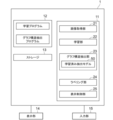
- FIG. 2 is a diagram showing a schematic configuration of a graph structure extraction device realized by installing a learning program and a graph structure extraction program on a computer.
- the graph structure extraction device 1 includes a CPU (Central Processing Unit) 11, a memory 12, and a storage 13 as a standard workstation configuration. Further, a display unit 14 such as a liquid crystal display and an input unit 15 such as a keyboard and a mouse are connected to the graph structure extraction device 1.
- a CPU Central Processing Unit
- memory 12 main memory
- storage 13 as a standard workstation configuration
- a display unit 14 such as a liquid crystal display
- an input unit 15 such as a keyboard and a mouse are connected to the graph structure extraction device 1.
- the storage 13 is composed of a hard disk drive or the like, and is a target image to be extracted from the graph structure acquired from the image storage server 3 via the network 4, a learning image for learning a neural network, and processing as described later. Various information including the information necessary for the computer is stored.
- the learning program and the graph structure extraction program are stored in the memory 12.
- the learning program includes a learning image for learning the extraction model described later, an image acquisition process for acquiring a target image to be extracted with a graph structure, and a loss for learning the extraction model. It defines a learning process that derives and trains the extraction model based on the loss.
- the graph structure extraction program as a process to be executed by the CPU 11, is a graph structure extraction process that outputs the graph structure extraction result included in the target image to be the target image of the graph structure extraction acquired by the image acquisition process, according to the graph structure extraction result.
- a labeling process for labeling tubular structures (arteries and veins in the present embodiment) included in the target image, and a display control process for displaying the labeled target image on the display unit 14 are defined.
- the computer functions as an image acquisition unit 21, a learning unit 22, a graph structure extraction unit 23, a labeling unit 24, and a display control unit 25. ..
- the image acquisition unit 21 acquires a three-dimensional image including a graph structure as a target image from the image storage server 3 via an interface (not shown) connected to the network.
- a three-dimensional image of the liver including arteries and veins as a tubular structure is used as a target image.
- the blood vessels of the liver include portal veins in addition to arteries and veins, but here, for the sake of explanation, only arteries and veins will be described.
- the image acquisition unit 21 acquires a learning image for learning and correct answer data described later.
- the learning unit 22 obtains feature vectors of a plurality of nodes constituting the graph structure of the tubular structure from a target image including one or more tubular structures (two tubular structures, an artery and a vein in the present embodiment). Learn the extraction model to be extracted. Specifically, the learning unit 22 creates a feature map in which the distances of the feature vectors between the nodes belonging to the same graph structure included in the target image are distributed corresponding to the topological distance which is the distance on the path of the graph structure. The extraction model is trained so that it can be output.
- FIG. 3 is a schematic block diagram for explaining the configuration of the extraction model and the learning process.
- the learning unit 22 inputs the learning image 31 and the correct answer data 32 into the extraction model 30, and causes the learning feature map 33 to be output.
- the learning feature map 33 is formed by clustering and distributing the feature vectors of the nodes in the graph structure included in the learning image 31 into the individual graph structures included in the learning image 31.
- the learning image 31 includes arteries and veins contained in the liver.
- the correct answer data 32 is data in which the graph structures of the arteries and veins included in the learning image 31 are distinguished.
- arteries and veins are distinguished by showing the graph structure of arteries with solid lines and the graph structure of veins with broken lines.
- the feature map 33 shown in FIG. 3 the distribution of the feature vector in the graph structure of the artery is shown by a solid line, and the distribution of the feature vector in the graph structure of the vein is shown by a broken line.
- the extraction model 30 is composed of a convolutional neural network (hereinafter referred to as CNN (Convolutional Neural Network)), which is one of multi-layer neural networks in which a plurality of processing layers are hierarchically connected. Further, since all the input layers of the processing layer of the CNN are convolutional layers, the CNN is a full-layer convolutional neural network.
- the convolution layer performs convolution processing using various kernels on the input image, and outputs a feature map consisting of feature data obtained by the convolution processing.
- the convolution layer applies the kernel to the entire input image or feature map output from the previous processing layer, shifting the pixels of interest of the kernel. Further, the convolution layer applies an activation function such as a sigmoid function to the convolution value, and outputs the feature map 33.
- an activation function such as a sigmoid function
- the learning unit 22 inputs the learning image 31 and the correct answer data 32 representing the extraction results of the nodes having a plurality of graph structures included in the learning image 31 into the learning model 30, so that the learning model 30 Outputs the learning feature map 33 for the learning image 31 from.
- the extraction model 30 is used for learning so that the distance of the feature vectors between the nodes belonging to the same graph structure included in the training image 31 corresponds to the topological distance which is the distance on the path of the graph structure.
- the feature map 33 of is generated.
- the feature map 33 for learning is such that the distance between the feature vectors belonging to the same graph structure is small and the distance between the feature vectors belonging to different graph structures is large. To generate.
- the learning unit 22 sets the loss L between the nodes on the graph structure of the learning image 31 based on the distribution of the plurality of feature vector groups in the learning feature map 33 and the correct answer data 32, and sets the learning image 31. It is derived based on the error between the distance of the feature vector between the nodes belonging to the same graph structure included in and the topological distance which is the distance on the path of the graph structure between the nodes. In the learning unit 22, the distance between the feature vectors belonging to the pixels belonging to the same graph structure becomes smaller, and the feature vectors belonging to the nodes belonging to different graph structures are described in the learning unit 22. The loss L is derived so that the distance between the feature vectors becomes large.
- FIG. 4 is a diagram for explaining a topological distance.
- the Euclidean distance between the two nodes N1 and N2 is the length of the straight line 41 connecting the two nodes N1 and N2.
- the topological distance is the distance on the path of the graph structure 40 with respect to the two nodes N1 and N2 in the same graph structure 40.
- the length on the path of the graph structure 40 shown by the thick line existing between the nodes N1 and N2 is the topological distance 42 of the nodes N1 and N2.
- FIG. 5 is a conceptual diagram of the generation of the feature map.
- FIG. 5 shows the generation of a partial feature map 33A for each of the arteries and veins included in the partial region 31A of the learning image 31.
- the nodes on the graph structure of the artery shown by the solid line are shown by white circles
- the nodes on the graph structure of the veins shown by the broken lines are shown by black circles
- the partial feature map 33A the nodes on the graph structure of the artery are shown.
- the node feature vector is indicated by a white circle
- the node feature vector on the graph structure of the vein is indicated by a black circle.
- the feature map is generated so that the distance between the nodes belonging to the same graph structure corresponds to the topological distance which is the distance on the path of the graph structure. Further, in the present embodiment, the feature map is generated so that the distances of the feature vectors between the nodes belonging to different graph structures are separated as shown by the double-headed arrows in FIG. As a result, the feature vector is distributed in the feature space reflecting the topological distance between the nodes. Further, the feature vectors are clustered and distributed in cluster C1 composed of white circle nodes and cluster C2 composed of black circle nodes.
- the loss L is shown in the following formula (1)
- the function F is shown in the following formula (2).
- the loss L in relation to a plurality of nodes j included in the predetermined range Ni adjacent to the node i is derived for all the samples, that is, all the nodes on the graph structure. This is to reduce the amount of calculation for learning and graph structure extraction described later, and to efficiently perform the calculation for learning and graph structure extraction.
- the size of the range Ni may be appropriately set according to the processing capacity of the apparatus.
- the derivation of the loss L is not limited to the range Ni adjacent to the node i, and may be applied to all the nodes.
- “same graph” in the equation (2) indicates a case where i and j belong to the same graph structure, and "different graph” indicates a case where i and j belong to different graph structures.
- the function F shown in equation (2) derives the error between the distance of the feature vector between the nodes and the topological distance which is the distance on the path of the graph structure between the nodes for the nodes belonging to the same graph structure. It has become a thing. Further, the distance of the feature vectors between the nodes belonging to the same graph structure is small, and the distance of the feature vectors between the nodes belonging to different graph structures is large.
- the learning unit 22 derives the number of convolution layers, kernel coefficients, kernel size, and the like constituting the extraction model 30 so that the loss L is equal to or less than a predetermined threshold value, so that the extraction model 30 To learn.
- the extraction model 30 By learning the extraction model 30 in this way, when the target image is input, between the nodes belonging to the same graph structure with respect to the plurality of tubular structures (arteries and veins in the present embodiment) included in the target image.
- a trained extraction model 50 that outputs a feature map distributed in a distant state is constructed.
- the trained extraction model 50 is applied to the graph structure extraction unit 23.
- FIG. 6 is a diagram schematically showing a feature map output from the trained extraction model 50.
- the feature map 53 of the two-dimensional feature space is shown assuming that the feature vector is two-dimensional, but in reality, the feature map 53 is in the feature space of the dimension corresponding to the dimension of the feature vector. It is output.
- the area surrounded by the solid line represents the cluster of nodes having a graph structure, and the points in the cluster represent the feature vector of the nodes having a graph structure.
- feature vectors of nodes having the same graph structure are grouped in two clusters C1 and C2 in the feature space, and the two clusters C1 and C2 are distributed so as to be separated from each other.
- the target image contains two tubular structures (ie, arteries and veins) and the nodes of the graph structure of the two tubular structures are segmented.
- the feature vectors are distributed in a state reflecting the topological distance between the nodes of the graph structure in the target image. This means that the feature vectors of the nodes in the graph structure are distributed in a state where the continuity including the branching at the nodes is maintained.
- the graph structure extraction unit 23 extracts the graph structures of two tubular structures, arteries and veins, from the target image by the trained extraction model 50. That is, the graph structure extraction unit 23 inputs the target image to the trained extraction model 50, and outputs a feature map in which the feature vectors of the nodes of the graph structure of the tubular structure included in the target image are distributed from the trained extraction model 50. Let me. Then, the graph structure extraction unit 23 connects the nodes of the extracted graph structure so as not to have a closed circuit. At this time, based on the feature map, those having a short feature vector distance between the nodes are sequentially connected. As a result, the graph structure extraction unit 23 extracts the graph structure from the target image.
- the graph structure extraction unit 23 has the graph structure G1 of the arteries and veins in the liver included in the target image 55 as shown in FIG. , G2 is extracted.
- the solid line shows the graph structure of the artery
- the broken line shows the graph structure of the vein.
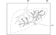
- the labeling unit 24 labels the tubular structure included in the target image 55 based on the graph structure extraction result output by the graph structure extraction unit 23. For example, when the graph structures G1 and G2 of arteries and veins in the liver are extracted as shown in FIG. 7, the same signal value as each node of each graph structure G1 and G2 in the target image 55 is obtained as shown in FIG.
- the regions consisting of the pixels are labeled as an arterial region A1 and a vein region A2, respectively. Labeling may be performed by assigning different labels to the arterial region A1 and the venous region A2.
- the arterial region A1 and the vein region A2 are labeled in the target image 55 by assigning a solid line label to the artery contour and a broken line label to the vein contour. Labeling may be performed by imparting different colors or hatching to arteries and veins.
- the display control unit 25 displays the labeled target image 55 on the display unit 14.
- FIG. 9 is a flowchart showing the learning process performed in the present embodiment. It is assumed that the learning image and the correct answer data are acquired by the image acquisition unit 21 from the image storage server 3 and stored in the storage 13.
- the learning unit 22 acquires a set of learning images and correct answer data from a plurality of learning images and correct answer data stored in the storage 13 (step ST1).
- the learning unit 22 inputs the learning image 31 and the correct answer data 32 to the extraction model 30 to output the learning feature map 33, and derives the loss L.
- the learning unit 22 learns the extraction model 30 so that the loss L becomes equal to or less than a predetermined threshold value (step ST2).
- step ST1 the process returns to step ST1
- the next learning image 31 and the correct answer data 32 are acquired from the storage 13, and the processes of steps ST1 and ST2 are repeated.
- the trained extraction model 50 is constructed.
- the learning unit 22 repeats learning until the loss L becomes equal to or less than a predetermined threshold value, the learning unit 22 may repeat learning a predetermined number of times.
- FIG. 10 is a flowchart of the graph structure extraction process performed in the present embodiment.
- the image acquisition unit 21 acquires the target image (step ST11), and the graph structure extraction unit 23 outputs the graph structure extraction result included in the target image 55 (step ST12).
- the labeling unit 24 labels the tubular structure based on the graph structure extracted from the target image 55 based on the graph structure extraction result (step ST13).
- the display control unit 25 displays the labeled target image on the display unit 14 (step ST14), and ends the process.
- the graph structure of the tubular structure included in the target image when the graph structure of the tubular structure included in the target image is extracted, by inputting the target image into the trained extraction model 50, the features between the nodes belonging to the same graph structure
- the feature map is output so that the distance of the vector corresponds to the topological distance which is the distance on the path of the graph structure, and the graph structure is extracted from the target image. Therefore, the graph structure can be extracted from the target image while the continuity of the graph structure including branching and the like is maintained by reflecting the topological distance in the graph structure. Therefore, according to the present embodiment, the graph structure can be accurately extracted from the target image.
- the loss is caused by a small distance between the feature vectors belonging to the same graph structure and a large distance between the node belonging to the different graph structure.
- each of the plurality of tubular structures included in the target image is labeled, but the present invention is not limited to this. Only a part of the plurality of tubular structures may be labeled.
- the arteries and veins of the liver included in the target image are extracted as a graph structure, but the present invention is not limited to this.
- the techniques of the present disclosure can also be applied to extract the graph structure of the portal vein in addition to the arteries and veins of the liver.
- the correct answer data for the learning image is a distinction between arteries, veins and veins.
- the techniques of the present disclosure can also be applied to extract graph structures of lung bronchi, as well as lung arteries and veins, as well as lung bronchi, arteries and veins.
- a three-dimensional medical image is used as the target image, but the present invention is not limited to this.
- the individual tomographic images that make up the three-dimensional medical image may be used as the target image.
- a two-dimensional X-ray image acquired by simple X-ray photography may be used as the target image.
- a learning image corresponding to the type of the target image is prepared, and the extraction model 30 is trained.
- a hardware-like processing unit that executes various processes such as an image acquisition unit 21, a learning unit 22, a graph structure extraction unit 23, a labeling unit 24, and a display control unit 25.
- various processors Processors
- the various processors include a CPU, which is a general-purpose processor that executes software (program) and functions as various processing units, and a circuit after manufacturing an FPGA (Field Programmable Gate Array) or the like.
- Dedicated electricity which is a processor with a circuit configuration specially designed to execute specific processing such as programmable logic device (PLD), ASIC (Application Specific Integrated Circuit), which is a processor whose configuration can be changed. Circuits and the like are included.
- One processing unit may be composed of one of these various processors, or a combination of two or more processors of the same type or different types (for example, a combination of a plurality of FPGAs or a combination of a CPU and an FPGA). ) May be configured. Further, a plurality of processing units may be configured by one processor.
- one processor is configured by a combination of one or more CPUs and software, as represented by a computer such as a client and a server. There is a form in which this processor functions as a plurality of processing units.
- SoC System On Chip
- the various processing units are configured by using one or more of the various processors as a hardware structure.
- circuitry in which circuit elements such as semiconductor elements are combined can be used.
Landscapes
- Engineering & Computer Science (AREA)
- Theoretical Computer Science (AREA)
- Physics & Mathematics (AREA)
- General Physics & Mathematics (AREA)
- Evolutionary Computation (AREA)
- Health & Medical Sciences (AREA)
- General Health & Medical Sciences (AREA)
- Computing Systems (AREA)
- Artificial Intelligence (AREA)
- Software Systems (AREA)
- Multimedia (AREA)
- Computer Vision & Pattern Recognition (AREA)
- Biomedical Technology (AREA)
- Molecular Biology (AREA)
- Data Mining & Analysis (AREA)
- Mathematical Physics (AREA)
- Computational Linguistics (AREA)
- Biophysics (AREA)
- General Engineering & Computer Science (AREA)
- Life Sciences & Earth Sciences (AREA)
- Databases & Information Systems (AREA)
- Medical Informatics (AREA)
- Quality & Reliability (AREA)
- Human Computer Interaction (AREA)
- Vascular Medicine (AREA)
- Image Analysis (AREA)
- Apparatus For Radiation Diagnosis (AREA)
Abstract
学習部が、1以上の管状構造物が含まれる対象画像から、管状構造物のグラフ構造を構成する複数のノードの特徴ベクトルを抽出する抽出モデルに、学習用画像および学習用画像に含まれるグラフ構造の正解データを入力することにより、学習用画像におけるグラフ構造上のノード間の損失を、同一のグラフ構造に属するノード間の特徴ベクトルの距離と、ノード間のグラフ構造の経路上の距離であるトポロジカル距離との誤差に基づいて導出し、損失に基づいて抽出モデルを学習する。
Description
本開示は、画像に含まれるグラフ構造を抽出するための抽出モデルを学習する学習装置、方法およびプログラム、画像に含まれるグラフ構造を抽出するグラフ構造抽出装置、方法およびプログラム、並びに学習済み抽出モデルに関するものである。
近年、ディープラーニング(深層学習)を用いた機械学習の技術が注目を集めている。とくに、画像に含まれる物体を識別するクラス分類の分野における様々な技術が提案されている。例えば、画像の全ピクセルをピクセル単位でラベリングすることによりクラス分類を行うセマンティックセグメンテーションが公知である。しかしながら、セマンティックセグメンテーションは、同一カテゴリの物体であれば個々を区別しないでセグメンテーションを行うことから、同一カテゴリの物体が重なっている場合、個々の物体を区別することができない。このため、個々の物体を区別してセグメンテーションするインスタンスセグメンテーションの手法が提案されている(例えば、下記の非特許文献1~3参照)。インスタンスセグメンテーションを用いることにより、同一カテゴリの物体であっても、個々の物体を区別してセグメンテーションを行うことが可能となるため、同一カテゴリの物体が重なっていても、物体を個別にセグメンテーションすることができる。
非特許文献1:Semantic Instance Segmentation with a Discriminative Loss Function、Bert De Brabandere, Davy Neven, Luc Van Gool、Computer Vision and Pattern Recognition、"Deep Learning for Robotic Vision", workshop at CVPR 2017、Submitted on 8 Aug 2017
非特許文献2:Semantic Instance Segmentation via Deep Metric Learning、Alireza Fathi, Zbigniew Wojna, Vivek Rathod, Peng Wang, Hyun Oh Song, Sergio Guadarrama, Kevin P. Murphy、Computer Vision and Pattern Recognition、Submitted on 30 Mar 2017
非特許文献3:Recurrent Pixel Embedding for Instance Grouping、Shu Kong, Charless Fowlkes、Computer Vision and Pattern Recognition (cs.CV); Machine Learning (cs.LG); Multimedia (cs.MM)、Submitted on 22 Dec 2017
非特許文献2:Semantic Instance Segmentation via Deep Metric Learning、Alireza Fathi, Zbigniew Wojna, Vivek Rathod, Peng Wang, Hyun Oh Song, Sergio Guadarrama, Kevin P. Murphy、Computer Vision and Pattern Recognition、Submitted on 30 Mar 2017
非特許文献3:Recurrent Pixel Embedding for Instance Grouping、Shu Kong, Charless Fowlkes、Computer Vision and Pattern Recognition (cs.CV); Machine Learning (cs.LG); Multimedia (cs.MM)、Submitted on 22 Dec 2017
一方、医療分野においては、医用画像を用いて血管および気管支等の管状構造物の手術をシミュレーションしたり、管状構造物を分析したりすることが行われている。このようなシミュレーションおよび分析等を行うためには、医用画像から管状構造物のグラフ構造を抽出する必要がある。この場合、例えば、上述したインスタンスセグメンテーションの手法により、管状構造物を構成する同一カテゴリの個々の物体を区別してセグメンテーションし、その後、グラフの起点から例えば類似度関数を使用して、連続点を接続することにより、グラフ構造を抽出することができる。
しかしながら、類似度関数を用いた場合、グラフの分岐位置において、グラフ構造を管状構造物に沿って連続して接続できない場合が生じる。とくに管状構造物が動脈および静脈の場合、画像上において動脈と静脈とが交差して存在する場合には、両者を区別して接続することが難しい場合がある。
本開示は上記事情に鑑みなされたものであり、画像に含まれるグラフ構造を精度よく抽出できるようにすることを目的とする。
本開示による学習装置は、1以上の管状構造物が含まれる対象画像から、管状構造物のグラフ構造を構成する複数のノードの特徴ベクトルを抽出する抽出モデルに、学習用画像および学習用画像に含まれるグラフ構造の正解データを入力することにより、学習用画像におけるグラフ構造上のノード間の損失を、同一のグラフ構造に属するノード間の特徴ベクトルの距離と、ノード間のグラフ構造の経路上の距離であるトポロジカル距離との誤差に基づいて導出し、損失に基づいて抽出モデルを学習する学習部を備える。
グラフ構造とは、血管および気管支等の管状構造物の長さ方向に延在する線状の構造である。グラフ構造は、管状構造物の形状を表すものとなっている。また、ノードとはグラフ構造上に存在する、グラフ構造を構成する点である。
「トポロジカル距離」とは、同一のグラフ構造におけるノード間の、グラフ構造上の距離である。例えば、グラフ構造が円弧をなす場合、円弧上の2点のユークリッド距離は2点を結ぶ直線、すなわち弦の長さとなるが、円弧状の2点のトポロジカル距離は、グラフ構造上における2点間の経路、すなわち、2点を結ぶ円弧の長さとなる。
なお、本開示による学習装置においては、学習部は、2以上の異なるグラフ構造を含む学習用画像に関して、損失を、さらに学習用画像における同一のグラフ構造に属するノード間の特徴ベクトルの距離が小さくなるように導出するものであってもよい。
また、本開示による学習装置においては、学習部は、損失を、さらに異なるグラフ構造に属するノード間の特徴ベクトルの距離が大きくなるように導出するものであってもよい。
また、本開示による学習装置においては、抽出モデルは、全層畳み込みニューラルネットワークであってもよい。
また、本開示による学習装置においては、対象画像および学習用画像は、医用3次元画像であってもよい。
また、本開示による学習装置においては、管状構造物は動脈および静脈であってもよい。
また、本開示による学習装置においては、管状構造物は肝臓における動脈、静脈および門脈であってもよい。
また、本開示による学習装置においては、管状構造物は気管支であってもよい。
本開示によるグラフ構造抽出装置は、本開示による学習装置により学習された抽出モデルが適用されてなり、対象画像の入力により対象画像に含まれるグラフ構造の抽出結果を出力する抽出部を備える。
なお、本開示によるグラフ構造抽出装置においては、グラフ構造の抽出結果に応じて、対象画像に含まれる管状構造物にラベリングを行うラベリング部と、
管状構造物がラベリングされた対象画像を表示部に表示する表示制御部とをさらに備えるものであってもよい。
管状構造物がラベリングされた対象画像を表示部に表示する表示制御部とをさらに備えるものであってもよい。
本開示による学習済み抽出モデルは、本開示による学習装置により学習された抽出モデルを含む。
本開示による学習方法は、1以上の管状構造物が含まれる対象画像から、管状構造物のグラフ構造を構成する複数のノードの特徴ベクトルを抽出する抽出モデルに、学習用画像および学習用画像に含まれるグラフ構造の正解データを入力することにより、学習用画像におけるグラフ構造上のノード間の損失を、同一のグラフ構造に属するノード間の特徴ベクトルの距離と、ノード間のグラフ構造の経路上の距離であるトポロジカル距離との誤差に基づいて導出し、
損失に基づいて抽出モデルを学習する。
損失に基づいて抽出モデルを学習する。
本開示によるグラフ構造抽出方法は、本開示による学習方法により学習された抽出モデルが適用されてなり、対象画像の入力により、対象画像に含まれるグラフ構造の抽出結果を出力する。
なお、本開示による学習方法およびグラフ構造抽出方法をコンピュータに実行させるためのプログラムとして提供してもよい。
本開示による他の学習装置は、コンピュータに実行させるための命令を記憶するメモリと、
記憶された命令を実行するよう構成されたプロセッサとを備え、プロセッサは、
1以上の管状構造物が含まれる対象画像から、管状構造物のグラフ構造を構成する複数のノードの特徴ベクトルを抽出する抽出モデルに、学習用画像および学習用画像に含まれるグラフ構造の正解データを入力することにより、学習用画像におけるグラフ構造上のノード間の損失を、同一のグラフ構造に属するノード間の特徴ベクトルの距離と、ノード間のグラフ構造の経路上の距離であるトポロジカル距離との誤差に基づいて導出し、
損失に基づいて抽出モデルを学習する処理を実行する。
記憶された命令を実行するよう構成されたプロセッサとを備え、プロセッサは、
1以上の管状構造物が含まれる対象画像から、管状構造物のグラフ構造を構成する複数のノードの特徴ベクトルを抽出する抽出モデルに、学習用画像および学習用画像に含まれるグラフ構造の正解データを入力することにより、学習用画像におけるグラフ構造上のノード間の損失を、同一のグラフ構造に属するノード間の特徴ベクトルの距離と、ノード間のグラフ構造の経路上の距離であるトポロジカル距離との誤差に基づいて導出し、
損失に基づいて抽出モデルを学習する処理を実行する。
本開示による他のグラフ構造抽出装置は、コンピュータに実行させるための命令を記憶するメモリと、
記憶された命令を実行するよう構成されたプロセッサとを備え、プロセッサは、
本開示による学習方法により学習された、抽出モデルを含む学習済み抽出モデルが適用されてなり、対象画像の入力により、対象画像に含まれるグラフ構造の抽出結果を出力する処理を実行する。
記憶された命令を実行するよう構成されたプロセッサとを備え、プロセッサは、
本開示による学習方法により学習された、抽出モデルを含む学習済み抽出モデルが適用されてなり、対象画像の入力により、対象画像に含まれるグラフ構造の抽出結果を出力する処理を実行する。
本開示によれば、対象画像からグラフ構造を精度よく抽出することができる。
以下、図面を参照して本開示の実施形態について説明する。図1は、本開示の実施形態による学習装置およびグラフ構造抽出装置を適用した、診断支援システムの概要を示すハードウェア構成図である。図1に示すように、診断支援システムでは、本実施形態による学習装置およびグラフ構造抽出装置(以下、単にグラフ構造抽出装置とする)1、3次元画像撮影装置2、および画像保管サーバ3が、ネットワーク4を経由して通信可能な状態で接続されている。
3次元画像撮影装置2は、被写体の診断対象となる部位を撮影することにより、その部位を表す医用3次元画像を生成する装置であり、具体的には、CT装置、MRI装置、およびPET(Positron Emission Tomography)装置等である。3次元画像撮影装置2により生成された3次元画像は画像保管サーバ3に送信され、保存される。なお、本実施形態においては、3次元画像撮影装置2はCT装置であり、被写体の診断対象となる部位を含むCT画像を3次元画像として生成する。なお、3次元画像は複数の断層画像からなる。また、本実施形態においては、被写体を人体の肝臓とし、肝臓に含まれる動脈および静脈のグラフ構造を抽出の対象とする。
画像保管サーバ3は、各種データを保存して管理するコンピュータであり、大容量外部記憶装置およびデータベース管理用ソフトウェアを備えている。画像保管サーバ3は、有線あるいは無線のネットワーク4を介して他の装置と通信を行い、画像データ等を送受信する。具体的には3次元画像撮影装置2で生成された3次元画像の画像データを含む各種データをネットワーク経由で取得し、大容量外部記憶装置等の記録媒体に保存して管理する。なお、画像データの格納形式およびネットワーク4経由での各装置間の通信は、DICOM(Digital Imaging and Communication in Medicine)等のプロトコルに基づいている。また、本実施形態においては、画像保管サーバ3は、後述する抽出モデルの学習のための学習用画像も保管して管理している。
本実施形態の学習装置を含むグラフ構造抽出装置1は、1台のコンピュータに、本実施形態の学習プログラムおよびグラフ構造抽出プログラムをインストールしたものである。コンピュータは、診断を行う医師が直接操作するワークステーションまたはパーソナルコンピュータでもよいし、それらとネットワークを介して接続されたサーバコンピュータでもよい。学習プログラムおよびグラフ構造抽出プログラムは、ネットワークに接続されたサーバコンピュータの記憶装置、もしくはネットワークストレージに、外部からアクセス可能な状態で記憶され、要求に応じて医師が使用するコンピュータにダウンロードされ、インストールされる。または、DVD(Digital Versatile Disc)あるいはCD-ROM(Compact Disc Read Only Memory)等の記録媒体に記録されて配布され、その記録媒体からコンピュータにインストールされる。
図2は、コンピュータに学習プログラムおよびグラフ構造抽出プログラムをインストールすることにより実現されるグラフ構造抽出装置の概略構成を示す図である。図2に示すように、グラフ構造抽出装置1は、標準的なワークステーションの構成として、CPU(Central Processing Unit)11、メモリ12およびストレージ13を備えている。また、グラフ構造抽出装置1には、液晶ディスプレイ等の表示部14、並びにキーボードおよびマウス等の入力部15が接続されている。
ストレージ13はハードディスクドライブ等からなり、ネットワーク4を経由して画像保管サーバ3から取得したグラフ構造抽出の対象となる対象画像、後述するようにニューラルネットワークの学習を行うための学習用画像、および処理に必要な情報を含む各種情報が記憶されている。
また、メモリ12には、学習プログラムおよびグラフ構造抽出プログラムが記憶されている。学習プログラムは、CPU11に実行させる処理として、後述する抽出モデルを学習するための学習用画像およびグラフ構造抽出の対象となる対象画像を取得する画像取得処理、並びに抽出モデルの学習のための損失を導出し、損失に基づいて抽出モデルを学習する学習処理を規定する。
グラフ構造抽出プログラムは、CPU11に実行させる処理として、画像取得処理により取得したグラフ構造抽出の対象となる対象画像に含まれるグラフ構造抽出結果を出力するグラフ構造抽出処理、グラフ構造抽出結果に応じて、対象画像に含まれる管状構造物(本実施形態においては動脈および静脈)にラベリングを行うラベリング処理、およびラベリングされた対象画像を表示部14に表示する表示制御処理を規定する。
そして、CPU11が学習プログラムおよびグラフ構造抽出プログラムに従いこれらの処理を実行することで、コンピュータは、画像取得部21、学習部22、グラフ構造抽出部23、ラベリング部24および表示制御部25として機能する。
画像取得部21は、ネットワークに接続されたインターフェース(不図示)を介して、画像保管サーバ3から、グラフ構造を含む3次元画像を対象画像として取得する。本実施形態においては、管状構造物として動脈および静脈を含む肝臓の3次元画像を対象画像とする。なお、肝臓の血管には、動脈および静脈の他、門脈も含まれるが、ここでは説明のために動脈および静脈のみを対象として説明する。また、画像取得部21は、学習のための学習用画像および後述する正解データを取得する。
学習部22は、1以上の管状構造物(本実施形態においては動脈および静脈という2つの管状構造物)が含まれる対象画像から、管状構造物のグラフ構造を構成する複数のノードの特徴ベクトルを抽出する抽出モデルの学習を行う。具体的には、学習部22は、対象画像に含まれる同一のグラフ構造に属するノード間の特徴ベクトルの距離が、グラフ構造の経路上の距離であるトポロジカル距離に対応して分布する特徴マップを出力するように、抽出モデルの学習を行う。
図3は抽出モデルの構成および学習処理を説明するための概略ブロック図である。図3に示すように、学習部22は、抽出モデル30に学習用画像31および正解データ32を入力し、学習用の特徴マップ33を出力させる。学習用の特徴マップ33は、学習用画像31に含まれるグラフ構造におけるノードの特徴ベクトルが、学習用画像31に含まれる個々のグラフ構造にクラスタリングされて分布されてなる。
ここで、学習用画像31は、肝臓に含まれる動脈および静脈を含む。また、正解データ32は、学習用画像31に含まれる動脈および静脈のそれぞれのグラフ構造が区別されてなるデータである。なお、図3に示す正解データ32においては、動脈のグラフ構造を実線、静脈のグラフ構造を破線で示すことにより、動脈および静脈を区別している。また、図3に示す特徴マップ33では、動脈のグラフ構造における特徴ベクトルの分布を実線で示し、静脈のグラフ構造における特徴ベクトルの分布を破線で示している。
抽出モデル30は、複数の処理層が階層的に接続された多層ニューラルネットワークの1つである、畳み込みニューラルネットワーク(以下CNN(Convolutional Neural Network)とする)からなる。また、CNNが有する処理層は、入力される全層が畳み込み層からなるため、CNNは、全層畳み込みニューラルネットワークである。畳み込み層は、入力される画像に対して各種カーネルを用いた畳み込み処理を行い、畳み込み処理により得られた特徴量データからなる特徴マップを出力する。カーネルは、n×n画素サイズ(例えばn=3)を有し、各要素に重みが設定されている。具体的には、入力された画像のエッジを強調する微分フィルタのような重みが設定されている。畳み込み層は、カーネルの注目画素をずらしながら、入力された画像または前段の処理層から出力された特徴マップの全体にカーネルを適用する。さらに、畳み込み層は、畳み込みされた値に対して、シグモイド関数等の活性化関数を適用し、特徴マップ33を出力する。
本実施形態において、学習部22は、抽出モデル30に、学習用画像31および学習用画像31に含まれる複数のグラフ構造のノードの抽出結果を表す正解データ32を入力することにより、抽出モデル30から学習用画像31についての学習用の特徴マップ33を出力させる。本実施形態において、抽出モデル30は、学習用画像31に含まれる同一のグラフ構造に属するノード間の特徴ベクトルの距離が、グラフ構造の経路上の距離であるトポロジカル距離に対応するように学習用の特徴マップ33を生成する。さらに、本実施形態においては、同一のグラフ構造に属するノード間の特徴ベクトルの距離が小さくなり、かつ異なるグラフ構造に属するノード間の特徴ベクトルの距離が大きくなるように、学習用の特徴マップ33を生成する。
このため、学習部22は、学習用の特徴マップ33における複数の特徴ベクトル群の分布および正解データ32に基づいて、学習用画像31におけるグラフ構造上のノード間の損失Lを、学習用画像31に含まれる同一のグラフ構造に属するノード間の特徴ベクトルの距離と、ノード間のグラフ構造の経路上の距離であるトポロジカル距離との誤差に基づいて導出する。なお、学習部22は、同一のグラフ構造に属する画素間の特徴ベクトルの距離が小さくなり、かつ異なるグラフ構造に属するノード間の特徴ベクトルについては、
特徴ベクトル間の距離が大きくなるように損失Lを導出する。
特徴ベクトル間の距離が大きくなるように損失Lを導出する。
ここで、トポロジカル距離について説明する。図4はトポロジカル距離を説明するための図である。図4に示すように1つの分岐を有するグラフ構造40上における2つのノードN1,N2間の距離を考える。2つのノードN1,N2のユークリッド距離は、2つのノードN1,N2を結ぶ直線41の長さである。一方、トポロジカル距離は、同一のグラフ構造40における2つのノードN1,N2に関しての、グラフ構造40の経路上の距離である。図4に示すグラフ構造40の場合、ノードN1とノードN2との間に存在する太線で示すグラフ構造40の経路上の長さが、ノードN1,N2のトポロジカル距離42となる。
図5は特徴マップの生成の概念図である。なお、図5は、学習用画像31の部分領域31Aに含まれる動脈および静脈のそれぞれについての部分特徴マップ33Aの生成を示している。また、部分領域31Aにおいては、実線で示す動脈のグラフ構造上のノードを白丸で、破線で示す静脈のグラフ構造上のノードを黒丸で示し、部分特徴マップ33Aにおいては、動脈のグラフ構造上のノードの特徴ベクトルを白丸で、静脈のグラフ構造上のノードの特徴ベクトルを黒丸で示す。図5に示すように、本実施形態においては、同一のグラフ構造に属するノード間の距離が、グラフ構造の経路上の距離であるトポロジカル距離に対応するように特徴マップが生成される。また、本実施形態においては、異なるグラフ構造に属するノード間の特徴ベクトルの距離が、図5の両矢印に示すように離れるように、特徴マップが生成される。これにより、特徴ベクトルは特徴空間において、ノード間のトポロジカル距離が反映されて分布することとなる。さらに、特徴ベクトルは、白丸のノードからなるクラスタC1および黒丸のノードからなるクラスタC2にクラスタリングされて分布することとなる。
ここで、損失Lを下記の式(1)に、関数Fを下記の式(2)に示す。式(1)においては、すべてのサンプル、すなわちグラフ構造上の全ノードにおいて、ノードiに隣接する予め定められた範囲Niに含まれる複数のノードjとの関係における損失Lを導出している。これは、学習および後述するグラフ構造抽出のための演算量を低減して、学習およびグラフ構造抽出のための演算を効率よく行うためである。範囲Niのサイズは、装置の処理能力に応じて適宜設定すればよい。なお、損失Lの導出はノードiに隣接する範囲Niに限定されるものではなく、全ノードを対象としてもよい。ここで、式(2)における「same graph」はi,jが同一のグラフ構造に属する場合を、「different graph」はi,jが異なるグラフ構造に属する場合を示す。式(2)に示す関数Fは、同一のグラフ構造に属するノード間については、ノード間の特徴ベクトルの距離と、ノード間のグラフ構造の経路上の距離であるトポロジカル距離との誤差を導出するものとなっている。また、同一のグラフ構造に属するノード間の特徴ベクトルの距離が小さくなり、かつ異なるグラフ構造に属するノード間については、ノード間の特徴ベクトルの距離が大きくなるものとなっている。

学習部22は、損失Lが予め定められたしきい値以下となるように、抽出モデル30を構成する畳み込み層の数、カーネルの係数およびカーネルの大きさ等を導出することにより、抽出モデル30の学習を行う。このように抽出モデル30を学習することにより、対象画像が入力されると、対象画像に含まれる複数の管状構造物(本実施形態においては動脈および静脈)に関して、同一のグラフ構造に属するノード間の特徴ベクトルの距離がグラフ構造の経路上の距離であるトポロジカル距離に対応し、同位置のグラフ構造に属するノード間の特徴ベクトルの距離が小さくなり、かつ異なるグラフ構造に属するノードの特徴ベクトルが離れた状態で分布する特徴マップを出力する学習済み抽出モデル50が構築される。学習済み抽出モデル50はグラフ構造抽出部23に適用される。
図6は学習済み抽出モデル50から出力される特徴マップを模式的に示す図である。なお、図6においては、特徴ベクトルが2次元であるものとして2次元の特徴空間の特徴マップ53を示しているが、実際には特徴ベクトルの次元に対応する次元の特徴空間において特徴マップ53が出力される。また、図6においては実線で囲まれる領域がグラフ構造のノードのクラスタを、クラスタ内の点がグラフ構造のノードの特徴ベクトルを表す。図6に示す特徴マップ53においては、特徴空間に同一のグラフ構造のノードの特徴ベクトルが2つのクラスタC1,C2にまとまり、かつ2つのクラスタC1,C2が互いに離れるように分布している。これは、対象画像に2つの管状構造物(すなわち動脈および静脈)が含まれ、2つの管状構造物のグラフ構造のノードがセグメンテーションされていることを表す。また、クラスタC1,C2内においては、特徴ベクトルは対象画像中のグラフ構造のノード間のトポロジカル距離を反映させた状態で分布している。これは、グラフ構造のノードの特徴ベクトルが、ノードにおける分岐等を含めたその連続性を維持した状態で分布していることを表す。
グラフ構造抽出部23は、対象画像が入力されると、学習済み抽出モデル50により、対象画像から動脈および静脈という2つの管状構造物のグラフ構造を抽出する。すなわち、グラフ構造抽出部23は、対象画像を学習済み抽出モデル50に入力し、学習済み抽出モデル50から対象画像に含まれる管状構造物のグラフ構造のノードの特徴ベクトルが分布する特徴マップを出力させる。そして、グラフ構造抽出部23は、抽出されたグラフ構造のノードを閉回路を持たないように接続する。この際、特徴マップに基づいて、ノード間の特徴ベクトルの距離が近いものを順次接続する。これにより、グラフ構造抽出部23は、対象画像からグラフ構造を抽出する。
例えば、肝臓を含む対象画像55がグラフ構造抽出部23に入力された場合、グラフ構造抽出部23は、図7に示すように、対象画像55に含まれる肝臓内の動脈および静脈のグラフ構造G1,G2を抽出する。なお、図7においては、実線が動脈のグラフ構造を、破線が静脈のグラフ構造を示す。
ラベリング部24は、グラフ構造抽出部23が出力したグラフ構造抽出結果に基づいて、対象画像55に含まれる管状構造物のラベリングを行う。例えば、図7に示すように肝臓における動脈および静脈のグラフ構造G1,G2が抽出された場合、図8に示すように、対象画像55における各グラフ構造G1,G2の各ノードと同一信号値を有する画素からなる領域をそれぞれ動脈領域A1および静脈領域A2としてラベリングする。ラベリングは、動脈領域A1および静脈領域A2に対して、それぞれ異なるラベルを付与することにより行えばよい。図8においては、動脈の輪郭に実線のラベルと、静脈の輪郭に破線のラベルを付与することにより、対象画像55において、動脈領域A1および静脈領域A2のラベリングを行っている。なお、動脈および静脈に異なる色またはハッチングを付与することにより、ラベリングを行ってもよい。
表示制御部25は、ラベリングされた対象画像55を表示部14に表示する。
次いで、本実施形態において行われる処理について説明する。図9は本実施形態において行われる学習処理を示すフローチャートである。なお、学習用画像および正解データは画像保管サーバ3から画像取得部21により取得されて、ストレージ13に保存されているものとする。まず、学習部22がストレージ13に保存された複数の学習用画像および正解データから1組の学習用画像および正解データを取得する(ステップST1)。学習部22は、抽出モデル30に対して、学習用画像31および正解データ32を入力して学習用の特徴マップ33を出力させ、損失Lを導出する。そして、学習部22は、損失Lが予め定められたしきい値以下となるように、抽出モデル30を学習する(ステップST2)。
そして、ステップST1にリターンし、次の学習用画像31および正解データ32をストレージ13から取得して、ステップST1,ST2の処理を繰り返す。これにより、学習済み抽出モデル50が構築される。
なお、学習部22は、損失Lが予め定められたしきい値以下となるまで学習を繰り返すものとしているが、予め定められた回数の学習を繰り返すものであってもよい。
次いで、本実施形態において行われるグラフ構造抽出処理について説明する。図10は本実施形態において行われるグラフ構造抽出処理のフローチャートである。画像取得部21が対象画像を取得し(ステップST11)、グラフ構造抽出部23が対象画像55に含まれるグラフ構造抽出結果を出力する(ステップST12)。次いで、ラベリング部24が、グラフ構造抽出結果に基づいて対象画像55から抽出されたグラフ構造に基づいて、管状構造物のラベリングを行う(ステップST13)。そして、表示制御部25がラベリングされた対象画像を表示部14に表示し(ステップST14)、処理を終了する。
このように、本実施形態においては、対象画像に含まれる管状構造物のグラフ構造を抽出する場合、学習済み抽出モデル50に対象画像を入力することにより、同一のグラフ構造に属するノード間の特徴ベクトルの距離がグラフ構造の経路上の距離であるトポロジカル距離に対応するものとなるように特徴マップが出力されて、対象画像からグラフ構造が抽出される。このため、グラフ構造におけるトポロジカル距離を反映させて、分岐等を含めたグラフ構造の連続性を維持した状態で、対象画像からグラフ構造を抽出することができる。したがって、本実施形態によれば、対象画像からグラフ構造を精度よく抽出することができる。
また、2以上の異なるグラフ構造を含む学習用画像に関して、損失を、同一のグラフ構造に属するノード間の特徴ベクトルの距離が小さくなり、かつ異なるグラフ構造に属するノード間の特徴ベクトルの距離が大きくなるように導出することより、異なるグラフ構造に属するノードは、特徴空間において離れて存在するように特徴マップを出力することができる。このため、対象画像に含まれる異なるグラフ構造をそれぞれ別の構造として精度よく抽出することができる。
なお、上記実施形態においては、対象画像に含まれる複数の管状構造物のそれぞれをラベリングしているが、これに限定されるものではない。複数の管状構造物のうちの一部のみラベリングを行ってもよい。
また、上記実施形態においては、対象画像に含まれる肝臓の動脈および静脈をグラフ構造として抽出しているが、これに限定されるものではない。肝臓の動脈および静脈に加えて門脈のグラフ構造を抽出する場合にも本開示の技術を適用することが可能である。この場合、学習用画像に対する正解データは、動脈、静脈および静脈が区別されたものとなる。また、肺の気管支さらには、肺の動脈および静脈さらには肺の気管支、動脈および静脈のグラフ構造を抽出する場合にも本開示の技術を適用することができる。
また、上記実施形態においては、対象画像として3次元の医用画像を用いているがこれに限定されるものではない。3次元の医用画像を構成する個々の断層画像を対象画像として用いてもよい。また、単純X線撮影により取得された2次元のX線画像を対象画像として用いてもよい。この場合、対象画像の種類に応じた学習用画像が用意されて、抽出モデル30の学習が行われることとなる。
また、上記実施形態において、例えば、画像取得部21、学習部22、グラフ構造抽出部23、ラベリング部24および表示制御部25といった各種の処理を実行する処理部(Processing Unit)のハードウェア的な構造としては、次に示す各種のプロセッサ(Processor)を用いることができる。上記各種のプロセッサには、上述したように、ソフトウェア(プログラム)を実行して各種の処理部として機能する汎用的なプロセッサであるCPUに加えて、FPGA(Field Programmable Gate Array)等の製造後に回路構成を変更可能なプロセッサであるプログラマブルロジックデバイス(Programmable Logic Device :PLD)、ASIC(Application Specific Integrated Circuit)等の特定の処理を実行させるために専用に設計された回路構成を有するプロセッサである専用電気回路等が含まれる。
1つの処理部は、これらの各種のプロセッサのうちの1つで構成されてもよいし、同種または異種の2つ以上のプロセッサの組み合わせ(例えば、複数のFPGAの組み合わせまたはCPUとFPGAとの組み合わせ)で構成されてもよい。また、複数の処理部を1つのプロセッサで構成してもよい。
複数の処理部を1つのプロセッサで構成する例としては、第1に、クライアントおよびサーバ等のコンピュータに代表されるように、1つ以上のCPUとソフトウェアとの組み合わせで1つのプロセッサを構成し、このプロセッサが複数の処理部として機能する形態がある。第2に、システムオンチップ(System On Chip:SoC)等に代表されるように、複数の処理部を含むシステム全体の機能を1つのIC(Integrated Circuit)チップで実現するプロセッサを使用する形態がある。このように、各種の処理部は、ハードウェア的な構造として、上記各種のプロセッサの1つ以上を用いて構成される。
さらに、これらの各種のプロセッサのハードウェア的な構造としては、より具体的には、半導体素子等の回路素子を組み合わせた電気回路(Circuitry)を用いることができる。
1 グラフ構造抽出装置
2 3次元画像撮影装置
3 画像保管サーバ
4 ネットワーク
11 CPU
12 メモリ
13 ストレージ
14 ディスプレイ
15 入力部
21 画像取得部
22 学習部
23 グラフ構造抽出部
24 ラベリング部
25 表示制御部
30 抽出モデル
31 学習用画像
31A 部分領域
32 正解データ
33 学習用特徴マップ
33A 部分特徴マップ
40 グラフ構造
41 直線
42 トポロジカル距離
50 学習済み抽出モデル
55 対象画像
A1 動脈領域
A2 静脈領域
C1,C2 クラスタ
G1,G2 グラフ構造
N1,N2 ノード
2 3次元画像撮影装置
3 画像保管サーバ
4 ネットワーク
11 CPU
12 メモリ
13 ストレージ
14 ディスプレイ
15 入力部
21 画像取得部
22 学習部
23 グラフ構造抽出部
24 ラベリング部
25 表示制御部
30 抽出モデル
31 学習用画像
31A 部分領域
32 正解データ
33 学習用特徴マップ
33A 部分特徴マップ
40 グラフ構造
41 直線
42 トポロジカル距離
50 学習済み抽出モデル
55 対象画像
A1 動脈領域
A2 静脈領域
C1,C2 クラスタ
G1,G2 グラフ構造
N1,N2 ノード
Claims (15)
- 1以上の管状構造物が含まれる対象画像から、前記管状構造物のグラフ構造を構成する複数のノードの特徴ベクトルを抽出する抽出モデルに、学習用画像および該学習用画像に含まれるグラフ構造の正解データを入力することにより、該学習用画像における前記グラフ構造上のノード間の損失を、同一の前記グラフ構造に属するノード間の特徴ベクトルの距離と、前記ノード間の前記グラフ構造の経路上の距離であるトポロジカル距離との誤差に基づいて導出し、前記損失に基づいて前記抽出モデルを学習する学習部を備えた学習装置。
- 前記学習部は、2以上の異なるグラフ構造を含む学習用画像に関して、前記損失を、さらに前記学習用画像における同一のグラフ構造に属するノード間の特徴ベクトルの距離が小さくなるように導出する請求項1に記載の学習装置。
- 前記学習部は、前記損失を、さらに異なるグラフ構造に属するノード間の特徴ベクトルの距離が大きくなるように導出する請求項2に記載の学習装置。
- 前記抽出モデルは、全層畳み込みニューラルネットワークである請求項1から3のいずれか1項に記載の学習装置。
- 前記対象画像および前記学習用画像は、医用3次元画像である請求項1から4のいずれか1項に記載の学習装置。
- 前記管状構造物は動脈および静脈である請求項1から5のいずれか1項に記載の学習装置。
- 前記管状構造物は肝臓における動脈、静脈および門脈である請求項1から5のいずれか1項に記載の学習装置。
- 前記管状構造物は気管支である請求項1から5のいずれか1項に記載の学習装置。
- 請求項1から8のいずれか1項に記載の学習装置により学習された前記抽出モデルが適用されてなり、前記対象画像の入力により該対象画像に含まれるグラフ構造の抽出結果を出力する抽出部を備えたグラフ構造抽出装置。
- 前記グラフ構造の抽出結果に応じて、前記対象画像に含まれる前記管状構造物にラベリングを行うラベリング部と、
前記管状構造物がラベリングされた対象画像を表示部に表示する表示制御部とをさらに備えた請求項9に記載のグラフ構造抽出装置。 - 請求項1から8のいずれか1項に記載の学習装置により学習された前記抽出モデルを含む学習済み抽出モデル。
- 1以上の管状構造物が含まれる対象画像から、前記管状構造物のグラフ構造を構成する複数のノードの特徴ベクトルを抽出する抽出モデルに、学習用画像および該学習用画像に含まれるグラフ構造の正解データを入力することにより、該学習用画像における前記グラフ構造上のノード間の損失を、同一の前記グラフ構造に属するノード間の特徴ベクトルの距離と、前記ノード間の前記グラフ構造の経路上の距離であるトポロジカル距離との誤差に基づいて導出し、
前記損失に基づいて前記抽出モデルを学習する学習方法。 - 請求項12に記載の学習方法により学習された前記抽出モデルが適用されてなり、前記対象画像の入力により該対象画像に含まれるグラフ構造の抽出結果を出力するグラフ構造抽出方法。
- 1以上の管状構造物が含まれる対象画像から、前記管状構造物のグラフ構造を構成する複数のノードの特徴ベクトルを抽出する抽出モデルに、学習用画像および該学習用画像に含まれるグラフ構造の正解データを入力することにより、該学習用画像における前記グラフ構造上のノード間の損失を、同一の前記グラフ構造に属するノード間の特徴ベクトルの距離と、前記ノード間の前記グラフ構造の経路上の距離であるトポロジカル距離との誤差に基づいて導出する手順と、
前記損失に基づいて前記抽出モデルを学習する手順とをコンピュータに実行させる学習プログラム。 - 請求項12に記載の学習方法により学習された前記抽出モデルが適用されてなり、前記対象画像の入力により該対象画像に含まれるグラフ構造の抽出結果を出力する手順をコンピュータに実行させるグラフ構造抽出プログラム。
Priority Applications (3)
| Application Number | Priority Date | Filing Date | Title |
|---|---|---|---|
| JP2021534067A JP7261884B2 (ja) | 2019-07-25 | 2020-07-22 | 学習装置、方法およびプログラム、グラフ構造抽出装置、方法およびプログラム、並びに学習済み抽出モデル |
| EP20844461.2A EP4005487A4 (en) | 2019-07-25 | 2020-07-22 | LEARNING DEVICE, METHOD AND PROGRAM, GRAPHIC STRUCTURE EXTRACTION DEVICE, METHOD AND PROGRAM AND LEARNED EXTRACTION MODEL |
| US17/581,836 US12190556B2 (en) | 2019-07-25 | 2022-01-21 | Learning apparatus, learning method, and learning program, graph structure extraction apparatus, graph structure extraction method, and graph structure extraction program, and learned extraction model |
Applications Claiming Priority (2)
| Application Number | Priority Date | Filing Date | Title |
|---|---|---|---|
| JP2019-137034 | 2019-07-25 | ||
| JP2019137034 | 2019-07-25 |
Related Child Applications (1)
| Application Number | Title | Priority Date | Filing Date |
|---|---|---|---|
| US17/581,836 Continuation US12190556B2 (en) | 2019-07-25 | 2022-01-21 | Learning apparatus, learning method, and learning program, graph structure extraction apparatus, graph structure extraction method, and graph structure extraction program, and learned extraction model |
Publications (1)
| Publication Number | Publication Date |
|---|---|
| WO2021015232A1 true WO2021015232A1 (ja) | 2021-01-28 |
Family
ID=74194218
Family Applications (1)
| Application Number | Title | Priority Date | Filing Date |
|---|---|---|---|
| PCT/JP2020/028416 Ceased WO2021015232A1 (ja) | 2019-07-25 | 2020-07-22 | 学習装置、方法およびプログラム、グラフ構造抽出装置、方法およびプログラム、並びに学習済み抽出モデル |
Country Status (4)
| Country | Link |
|---|---|
| US (1) | US12190556B2 (ja) |
| EP (1) | EP4005487A4 (ja) |
| JP (1) | JP7261884B2 (ja) |
| WO (1) | WO2021015232A1 (ja) |
Cited By (1)
| Publication number | Priority date | Publication date | Assignee | Title |
|---|---|---|---|---|
| EP4734054A1 (en) | 2024-10-28 | 2026-04-29 | FUJIFILM Corporation | Image processing apparatus, image processing method, and image processing program |
Families Citing this family (4)
| Publication number | Priority date | Publication date | Assignee | Title |
|---|---|---|---|---|
| CN113034425B (zh) * | 2019-12-25 | 2024-05-28 | 阿里巴巴集团控股有限公司 | 数据处理方法、设备及存储介质 |
| CN113779358B (zh) * | 2021-09-14 | 2024-05-24 | 支付宝(杭州)信息技术有限公司 | 一种事件检测方法和系统 |
| CN115424720A (zh) * | 2022-08-31 | 2022-12-02 | 上海联影智能医疗科技有限公司 | 管状结构断裂补全方法、装置及计算机设备 |
| CN118845067B (zh) * | 2024-09-26 | 2025-02-28 | 浙江卡易智慧医疗科技有限公司 | 一种结合多视图融合的双臂上举ct影像质控检测方法 |
Citations (3)
| Publication number | Priority date | Publication date | Assignee | Title |
|---|---|---|---|---|
| US20100296709A1 (en) * | 2009-05-19 | 2010-11-25 | Algotec Systems Ltd. | Method and system for blood vessel segmentation and classification |
| JP2014236912A (ja) * | 2013-06-10 | 2014-12-18 | 株式会社島津製作所 | 画像処理装置およびその方法 |
| WO2017199246A1 (en) * | 2016-05-16 | 2017-11-23 | Cathworks Ltd. | Vascular selection from images |
Family Cites Families (2)
| Publication number | Priority date | Publication date | Assignee | Title |
|---|---|---|---|---|
| US6327387B1 (en) * | 1996-12-27 | 2001-12-04 | Fujitsu Limited | Apparatus and method for extracting management information from image |
| CN110957012B (zh) * | 2019-11-28 | 2021-04-09 | 腾讯科技(深圳)有限公司 | 化合物的性质分析方法、装置、设备及存储介质 |
-
2020
- 2020-07-22 JP JP2021534067A patent/JP7261884B2/ja active Active
- 2020-07-22 WO PCT/JP2020/028416 patent/WO2021015232A1/ja not_active Ceased
- 2020-07-22 EP EP20844461.2A patent/EP4005487A4/en active Pending
-
2022
- 2022-01-21 US US17/581,836 patent/US12190556B2/en active Active
Patent Citations (3)
| Publication number | Priority date | Publication date | Assignee | Title |
|---|---|---|---|---|
| US20100296709A1 (en) * | 2009-05-19 | 2010-11-25 | Algotec Systems Ltd. | Method and system for blood vessel segmentation and classification |
| JP2014236912A (ja) * | 2013-06-10 | 2014-12-18 | 株式会社島津製作所 | 画像処理装置およびその方法 |
| WO2017199246A1 (en) * | 2016-05-16 | 2017-11-23 | Cathworks Ltd. | Vascular selection from images |
Non-Patent Citations (7)
| Title |
|---|
| ALIREZA FATHIZBIGNIEW WOJNAVIVEK RATHODPENG WANGHYUN OH SONGSERGIO GUADARRAMAKEVIN P. MURPHY: "Semantic Instance Segmentation via Deep Metric Learning", COMPUTER VISION AND PATTERN RECOGNITION, 30 March 2017 (2017-03-30) |
| BERT DE BRABANDEREDAVY NEVENLUC VAN GOOL: "Deep Learning for Robotic Vision", COMPUTER VISION AND PATTERN RECOGNITION, 8 August 2017 (2017-08-08) |
| NEKOVEI, REZA ET AL.: "Back-Propagetion Network and its Configuration for Blood Vessel Detection in Angiograms", IEEE TRANSACTIONS ON NEURAL NETWORKS, vol. 6, no. 1, 1995, pages 64 - 72, XP000483006, DOI: 10.1109/72.363449 * |
| ROSSANT FLORENCE; BADELLINO MADDALENA; CHAVILLON ALEXANDRE; BLOCH ISABELLE; PAQUES MICHEL: "A Morphological Approach for Vessel Segmentation in Eye Fundus Images, with Quantitative Evaluation", JOURNAL OF MEDICAL IMAGING AND HEALTH INFORMATION, vol. 1, no. 1, 1 March 2011 (2011-03-01), pages 42 - 49, XP055883851, ISSN: 2156-7018, DOI: 10.1166/jmihi.2011.1006 * |
| See also references of EP4005487A4 |
| SHU KONGCHARLESS FOWLKES: "Recurrent Pixel Embedding for Instance Grouping", COMPUTER VISION AND PATTERN RECOGNITION, 22 December 2017 (2017-12-22) |
| SZYMCZAK, ANDRZEJ ET AL.: "Coronary vessel trees from 3D imagery: A topological approach", MEDICAL IMAGE ANALYSIS, vol. 10, no. 4, 2006, pages 548 - 559, XP005592214 * |
Cited By (1)
| Publication number | Priority date | Publication date | Assignee | Title |
|---|---|---|---|---|
| EP4734054A1 (en) | 2024-10-28 | 2026-04-29 | FUJIFILM Corporation | Image processing apparatus, image processing method, and image processing program |
Also Published As
| Publication number | Publication date |
|---|---|
| EP4005487A4 (en) | 2022-08-17 |
| JP7261884B2 (ja) | 2023-04-20 |
| US12190556B2 (en) | 2025-01-07 |
| JPWO2021015232A1 (ja) | 2021-01-28 |
| EP4005487A1 (en) | 2022-06-01 |
| US20220148286A1 (en) | 2022-05-12 |
Similar Documents
| Publication | Publication Date | Title |
|---|---|---|
| Wong et al. | Scribbleprompt: fast and flexible interactive segmentation for any biomedical image | |
| JP7261884B2 (ja) | 学習装置、方法およびプログラム、グラフ構造抽出装置、方法およびプログラム、並びに学習済み抽出モデル | |
| Cai et al. | A review of the application of deep learning in medical image classification and segmentation | |
| Kim et al. | Deep learning in medical imaging | |
| EP3635683B1 (en) | Systems and methods for anatomic structure segmentation in image analysis | |
| WO2020215984A1 (zh) | 基于深度学习的医学图像检测方法及相关设备 | |
| CN110807788A (zh) | 医学图像处理方法、装置、电子设备及计算机存储介质 | |
| CN119487545A (zh) | 分析医学图像 | |
| US12125208B2 (en) | Method and arrangement for automatically localizing organ segments in a three-dimensional image | |
| Giri et al. | Automatic liver segmentation using U-Net deep learning architecture for additive manufacturing | |
| CN112634255B (zh) | 脑部病灶检测模型的建立方法、装置以及计算机设备 | |
| JP7342120B2 (ja) | 学習装置、方法およびプログラム、クラス分類装置、方法およびプログラム、並びに学習済みモデル | |
| Gamage et al. | Instance-based segmentation for boundary detection of neuropathic ulcers through Mask-RCNN | |
| CN112862805B (zh) | 听神经瘤图像自动化分割方法及系统 | |
| Xie et al. | Optic disc and cup image segmentation utilizing contour-based transformation and sequence labeling networks | |
| EP4327333A1 (en) | Methods and systems for automated follow-up reading of medical image data | |
| US20260030775A1 (en) | Apparatus and method for object pose estimation in a medical image | |
| Devisri et al. | Fetal growth analysis from ultrasound videos based on different biometrics using optimal segmentation and hybrid classifier | |
| Ameen et al. | Explainable residual network for tuberculosis classification in the IoT era | |
| CN117115187B (zh) | 颈动脉壁分割方法、装置、计算机设备和存储介质 | |
| Wong et al. | Building disease detection algorithms with very small numbers of positive samples | |
| Ogiela et al. | Natural user interfaces in medical image analysis | |
| CN113822323A (zh) | 脑部扫描图像的识别处理方法、装置、设备及存储介质 | |
| JPWO2019208130A1 (ja) | 医療文書作成支援装置、方法およびプログラム、学習済みモデル、並びに学習装置、方法およびプログラム | |
| Sri et al. | Detection Of MRI Brain Tumor Using Customized Deep Learning Method Via Web App |
Legal Events
| Date | Code | Title | Description |
|---|---|---|---|
| 121 | Ep: the epo has been informed by wipo that ep was designated in this application |
Ref document number: 20844461 Country of ref document: EP Kind code of ref document: A1 |
|
| ENP | Entry into the national phase |
Ref document number: 2021534067 Country of ref document: JP Kind code of ref document: A |
|
| NENP | Non-entry into the national phase |
Ref country code: DE |
|
| WWE | Wipo information: entry into national phase |
Ref document number: 2020844461 Country of ref document: EP |