WO2021014576A1 - 端末及び無線通信方法 - Google Patents
端末及び無線通信方法 Download PDFInfo
- Publication number
- WO2021014576A1 WO2021014576A1 PCT/JP2019/028875 JP2019028875W WO2021014576A1 WO 2021014576 A1 WO2021014576 A1 WO 2021014576A1 JP 2019028875 W JP2019028875 W JP 2019028875W WO 2021014576 A1 WO2021014576 A1 WO 2021014576A1
- Authority
- WO
- WIPO (PCT)
- Prior art keywords
- resource
- transmission
- dci
- instruction
- symbol
- Prior art date
- Legal status (The legal status is an assumption and is not a legal conclusion. Google has not performed a legal analysis and makes no representation as to the accuracy of the status listed.)
- Ceased
Links
Images


Classifications
-
- H—ELECTRICITY
- H04—ELECTRIC COMMUNICATION TECHNIQUE
- H04W—WIRELESS COMMUNICATION NETWORKS
- H04W72/00—Local resource management
- H04W72/50—Allocation or scheduling criteria for wireless resources
- H04W72/56—Allocation or scheduling criteria for wireless resources based on priority criteria
- H04W72/566—Allocation or scheduling criteria for wireless resources based on priority criteria of the information or information source or recipient
- H04W72/569—Allocation or scheduling criteria for wireless resources based on priority criteria of the information or information source or recipient of the traffic information
-
- H—ELECTRICITY
- H04—ELECTRIC COMMUNICATION TECHNIQUE
- H04W—WIRELESS COMMUNICATION NETWORKS
- H04W72/00—Local resource management
- H04W72/12—Wireless traffic scheduling
- H04W72/1263—Mapping of traffic onto schedule, e.g. scheduled allocation or multiplexing of flows
- H04W72/1268—Mapping of traffic onto schedule, e.g. scheduled allocation or multiplexing of flows of uplink data flows
-
- H—ELECTRICITY
- H04—ELECTRIC COMMUNICATION TECHNIQUE
- H04W—WIRELESS COMMUNICATION NETWORKS
- H04W72/00—Local resource management
- H04W72/20—Control channels or signalling for resource management
- H04W72/23—Control channels or signalling for resource management in the downlink direction of a wireless link, i.e. towards a terminal
Definitions
- the present disclosure relates to terminals and wireless communication methods in next-generation mobile communication systems.
- LTE Long Term Evolution
- 3GPP Rel.10-14 LTE-Advanced (3GPP Rel.10-14) has been specified for the purpose of further increasing the capacity and sophistication of LTE (Third Generation Partnership Project (3GPP) Release (Rel.) 8, 9).
- a successor system to LTE for example, 5th generation mobile communication system (5G), 5G + (plus), New Radio (NR), 3GPP Rel.15 or later, etc.) is also being considered.
- 5G 5th generation mobile communication system
- 5G + plus
- NR New Radio
- 3GPP Rel.15 or later, etc. is also being considered.
- future wireless communication systems for example, 5G, NR, etc.
- high speed and large capacity for example, enhanced Mobile Broad Band (eMBB)
- a large number of terminals for example, massive Machine Type Communication (mMTC), Internet of Things).
- IoT massive Machine Type Communication
- ultra-high reliability and low latency for example, Ultra Reliable and Low Latency Communications (URLLC)
- URLLC Ultra Reliable and Low Latency Communications
- UL transmissions will be canceled (also referred to as cancellation, preemption, interruption, interrupt, interruption, etc.). To. If the UL transmission is not canceled properly, the system performance may deteriorate.
- one of the purposes of the present disclosure is to provide a terminal and a wireless communication method for appropriately canceling UL transmission.
- the terminal includes a receiving unit that receives downlink control information (DCI) regarding a resource start position in at least one of a time domain and a frequency domain, a particle size setting of the start position, and the DCI. Based on this, it has a control unit that cancels the uplink transmission using the resource.
- DCI downlink control information
- UL transmission can be appropriately canceled.
- FIG. 1A-1C are diagrams showing an example of DL preemption instructions.
- FIG. 2 is a diagram showing an example of eMBB PUSCH and URLLC PUSCH.
- 3A-3C are diagrams showing an example of a UL cancellation instruction using the bitmap 1.
- 4A-4C is a diagram showing an example of a UL cancellation instruction using the bitmap 2.
- 5A-5C are diagrams showing an example of UL cancellation instruction using RIV.
- 6A-6C are diagrams showing an example of UL cancellation instruction using SLIV.
- FIG. 7 is a diagram showing an example of a schematic configuration of a wireless communication system according to an embodiment.
- FIG. 8 is a diagram showing an example of the configuration of the base station according to the embodiment.
- FIG. 9 is a diagram showing an example of the configuration of the user terminal according to the embodiment.
- FIG. 10 is a diagram showing an example of the hardware configuration of the base station and the user terminal according to the embodiment.
- the traffic type may be identified at the physical layer based on at least one of the following: -Logical channels with different priorities-Modulation and Coding Scheme (MCS) table (MCS index table) -Channel Quality Indication (CQI) table-DCI format-Used for scrambling (masking) the Cyclic Redundancy Check (CRC) bits included (added) in the DCI (DCI format).
- MCS Modulation and Coding Scheme
- CQI Channel Quality Indication
- CRC Cyclic Redundancy Check
- the traffic type of PUSCH may be determined based on at least one of the following.
- -The MCS index table used to determine at least one of the modulation order, target coding rate, and TBS of the PUSCH (for example, whether or not to use the MCS index table 3).
- -RNTI used for CRC scrambling of DCI used for scheduling the PUSCH (for example, whether CRC scrambled by C-RNTI or MCS-C-RNTI).
- the traffic type may be associated with communication requirements (requirements such as delay and error rate, requirements), data type (voice, data, etc.) and the like.
- the difference between the URLLC requirement and the eMBB requirement may be that the URLLC latency is smaller than the eMBB delay, or the URLLC requirement may include a reliability requirement.
- the UL cancel instruction enables URLLC UL transmission of another UE by canceling the already scheduled or configured (configured) eMBB UL transmission for one UE.
- the eMBB UE detects the UL cancellation instruction, the UE cancels (cancels or cancels) the UL transmission.
- Canceling a UL transmission may be read as preempting a UL transmission, preempting a UL transmission, replacing a UL transmission, and the like.
- the UL cancel instruction may instruct to cancel the low priority UL transmission when a high priority UL transmission using a scheduled or set resource of the low priority UL transmission occurs.
- the UL cancellation instruction may interrupt the scheduled UL transmission to the UE that has received the UL cancellation instruction. Also, the UL cancel instruction may be used by the UE that receives the UL cancel instruction to notify a resource that the UE assumes that no transmission of the UE is intended.
- the UL cancellation instruction In order to realize the UL cancellation instruction, it is considered to support at least group common (GC) -downlink control information (DCI, physical downlink control channel (PDCCH)) for the cancellation instruction. It has not yet been decided whether to support UE-specific DCI for revocation instructions.
- GC group common
- DCI physical downlink control channel
- the time resource to which UL cancellation applies may be implicitly determined.
- the time resource may be determined by the minimum processing time for the cancel operation.
- the time resource to which UL cancellation applies may be explicitly indicated by the network.
- the time resource may be instructed by DCI or by radio resource control (RRC).
- RRC radio resource control
- the frequency resource to which UL cancellation applies may be explicitly indicated by the network.
- the time resource may be dictated by DCI or by RRC.
- the time resource to which the UL revocation applies may be explicitly indicated by the UL revocation DCI, or the frequency resource to which the UL revocation applies is determined by the UL revocation DCI. It may be explicitly instructed.
- the DL preemption instruction is used for the UE-to-UE multiplexing of DL transmission (DL UE-to-UE multiplexing, DL inter-UE multiplexing).
- the preemption instructions use DCI format 2_1 and include a 14-bit bitmap.
- DCI format 2_1 may have a CRC scrambled by interrupt (INT) -RNTI.
- Bitmap interpretation can be modified by higher layer signaling. Each bit may represent one OFDM symbol in the time domain and the entire bandwidth part (BWP) in the frequency domain, or two OFDM symbols in the time domain and BWP in the frequency domain. May represent half of.
- FIG. 1A-1C are diagrams showing an example of DL preemption instructions.
- a preemption instruction is transmitted to UE A that has already been scheduled.
- each bit in the preemption instruction corresponds to two OFDM symbols and half of the BWP in a particular slot after the DL preemption instruction.
- the part corresponding to one bit indicates the resource to be preempted (used for DL transmission to UE B).
- the second DL transmission resource of UE B overlaps with the DL transmission resource scheduled for UE A, so that the second DL transmission of UE B is scheduled for UE A. Preempt the DL transmission.
- the DL preemption instruction interrupts the scheduled DL transmission to UE A. Also, the DL preemption instruction is used by UE A to notify a resource that it assumes that no transmission to UE A is intended.
- URLLC PUSCH transmission supports mini-slot-based repetition (mini-slot-based repetition) and dynamic instruction of the number of repetitions in DCI.
- mini-slot-based repetition the UE repeatedly transmits the same data (for example, transport block (TB)) in units of a period shorter than one slot (for example, a mini-slot).
- TB transport block
- the number of data iterations may be set by higher layer signaling.
- URLLC PUSCH transmission supports at least inter-PUSCH-repetition frequency hopping (FH) and slot-to-slot FH. Repeated FH between PUSCHs performs FH between PUSCHs (repeats).
- FH inter-PUSCH-repetition frequency hopping
- slot-to-slot FH Repeated FH between PUSCHs performs FH between PUSCHs (repeats).
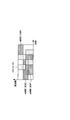
- FIG. 2 is a diagram showing an example of eMBB PUSCH and URLLC PUSCH.
- the URLLC PUSCH transmitted by the URLLC UE uses mini-slot-based repetition (4 repetitions of PUSCH of 2 symbols) and repetition FH between PUSCHs.
- the eMBB PUSCH scheduled for eMBB UEs # 1 and # 2 is canceled because it overlaps with the URLLC PUSCH.
- the eMBB PUSCH scheduled for eMBB UE # 3 does not overlap with the URLLC PUSCH, so it cannot be canceled.
- the present inventors have conceived a method of appropriately instructing resources for UL cancellation.
- the UE may instruct the UL cancellation resource by a UL cancellation instruction based on GC-PDCCH (GC-PDCCH based UL cancellation indication).
- GC-PDCCH based UL cancellation indication
- the UE may receive a DCI (group common DCI) including a UL cancellation instruction on the GC-PDCCH.
- the UE may cancel the UL transmission using the resource indicated by this DCI.
- the time resource to which UL revocation applies may be explicitly indicated by the UL revocation DCI.
- the time resource may be at least one of a slot, a minislot, and a symbol.
- the UE may explicitly set (instruct) the time domain resource instruction granularity (time granularity, granularity) by upper layer signaling.
- the time resource (eg, block) indicated by the UL cancellation instruction may be a continuous symbol over time particle size.
- the time granularity value may be a ⁇ 1, 2, 3, ... x ⁇ symbol.
- the maximum value x of the time granularity may be 7, may be 14, may be the number of symbols in the half slot, or may be the number of symbols in the slot.
- the UE may use the default value as the time particle size if the time particle size is not set.
- the default value may be 1 or 2 symbols.
- the time particle size may be set for at least one of the cell, the carrier (component carrier), and the BWP.
- the time resource to which UL cancellation is applied may be indicated by any of the fields of the following time resource instruction formats 1 to 3 in the DCI.
- Time resource instruction format 1 The time resource instruction format may be a bitmap. Each bit in the bitmap may be a symbol that is continuous over time particle size.
- bitmap The bitmap may follow at least one of the following bitmaps 1 and 2.
- the bitmap may explicitly indicate only the start symbol (start position) of the time resource.
- the end symbol of the time resource may be the last symbol of a particular time period.
- the specific period may be a slot containing a start symbol or a half slot containing a start symbol.
- bitmap 2 may explicitly indicate the start symbol (start position) of the time resource and the duration of the time resource (duration).
- bitmap instruction method For URLLC PUSCH using minislot-based repetition, the bitmap may follow either of the following bitmap instruction methods 1 and 2.
- the bitmap in the UL cancellation instruction may indicate the first iteration.
- the bitmap may indicate the starting position of the first iteration.
- the time resource used for the remaining iterations may be derived based on the number of iterations and the time resource used for the first iteration.
- the number of iterations may be indicated by another field within the UL revocation instruction.
- the second and subsequent repetitions may follow the first repetition.
- the length of the second and subsequent iterations may be equal to the first iteration.
- bitmap instruction method 2 For URLLC PUSCHs that use minislot-based iterations, the bitmap in the UL cancel instruction may indicate all time resources used for all iterations.
- the UL cancellation instruction does not have to include the number of repetitions.
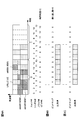
- bitmap 1 [[Specific example of bitmap 1]] 3A-3C are diagrams showing an example of a UL cancellation instruction using the bitmap 1.
- the URLLC UE repeats (sets) 8 repetitions of the URLLC 2 symbol PUSCH.
- This URLLC PUSCH overlaps with the already scheduled PUSCHs of eMBB UEs # 1 to # 3.
- the eMBB UEs # 1 to # 3 set the time granularity of the two symbols by higher layer signaling, and receive the UL cancellation instruction by GC-PDCCH.
- the bitmap size of the UL cancellation instruction is 14 bits. Since the time granularity is 2 symbols, each bit corresponds to a block of 2 symbols, and bits # 0 to # 13 are divided into 14 blocks (blocks # 0 to # 13, 28 symbols) covering slots # 0 and # 1. Correspond.
- FIG. 3B shows a bitmap using the bitmap instruction method 1 and a time resource indicated by the bitmap. Only bit # 2 of the bitmap in the UL cancellation instruction indicates 1. The number of repetitions in the UL cancellation instruction is 2.
- the start symbol of the first iteration of UL cancellation is block # 2 (symbol # 4 of slot # 0), and the end symbol of the first iteration is the final symbol of the same slot # 0 (symbol # 13).
- the length of one iteration is 5 blocks (10 symbols). Since the number of iterations is 2, the second iteration following the first iteration is from symbol # 0 to symbol # 9 in slot # 1. In this way, the eMBB UEs # 1 to # 3 determine the two instructed repetitions (from the symbol # 4 in slot # 0 to the symbol # 9 in slot # 1) as the time resource for UL cancellation.
- FIG. 3C shows a bitmap using the bitmap instruction method 2 and a time resource indicated by the bitmap. Only bits # 2 and # 7 of the bitmap in the UL cancellation instruction indicate 1.
- the start symbol of the first time resource corresponding to bit # 2 is block # 2 (symbol # 4 of slot # 0), and the corresponding end symbol is the final symbol of the same slot # 0 (symbol #). 13).
- the start symbol of the second time resource corresponding to bit # 7 is block # 7 (symbol # 0 of slot # 1), and the corresponding end symbol is the final symbol of the same slot # 1 (symbol # 13). Is.
- the eMBB UEs # 1 to # 3 determine the two instructed time resources (from the symbol # 4 in slot # 0 to the symbol # 13 in slot # 1) as the time resources for UL cancellation.
- bitmap 2 [[Specific example of bitmap 2]] 4A-4C are diagrams showing an example of UL cancellation instruction using bitmap 2.
- FIG. 4A is the same as that of FIG. 3A.
- FIG. 4B shows a bitmap using the bitmap instruction method 1 and a time resource indicated by the bitmap. Only bit # 2 of the bitmap in the UL cancellation instruction indicates 1. The number of repetitions in the UL cancellation instruction is 8.
- the start symbol of the first repetition of UL cancellation is block # 2 (symbol # 4 of slot # 0).
- the number of repetitions is 8 blocks (16 symbols).
- the eMBB UEs # 1 to # 3 determine the eight instructed repetitions (from the symbol # 4 in slot # 0 to the symbol # 9 in slot # 1) as the time resource for UL cancellation.
- FIG. 4C shows a bitmap using the bitmap instruction method 2 and a time resource indicated by the bitmap. Only bits # 2 to # 9 of the bitmap in the UL cancellation instruction indicate 1.
- the time resources for UL cancellation are blocks # 2 to # 9 (from symbol # 4 in slot # 0 to symbol # 9 in slot # 1).
- the eMBB UEs # 1 to # 3 determine the instructed blocks # 2 to # 9 (from the symbol # 4 in slot # 0 to the symbol # 9 in slot # 1) as the time resource for UL cancellation. ..
- Time resource instruction format 2 may be the same indication as the resource indication value (RIV) used for the indication of the frequency resource.
- the RIV for UL cancellation may be a value indicating the start symbol (start position, start block) and length (transmission length, number of blocks) of at least a part of the UL cancellation time resource.
- RIV may be the maximum value of the start position ⁇ (length-1) + the start position (maximum of the start position) when (maximum value of the start position-start position) is equal to or longer than the length.
- Value-start position) may be 0 if it is shorter than the length.
- RIV instruction method For URLLC PUSCH using minislot-based repetition, the RIV may follow either of the following RIV instruction methods 1 and 2.
- the RIV within the UL Cancellation Instruction may indicate the first iteration.
- the RIV may indicate the start symbol of the first iteration (start position, start block) and the length of the first iteration (number of blocks).
- the time resource used for the remaining iterations may be derived based on the number of iterations and the time resource used for the first iteration.
- the number of iterations may be indicated by another field within the UL revocation instruction.
- the second and subsequent repetitions may follow the first repetition.
- the length of the second and subsequent iterations may be equal to the first iteration.
- the RIV in the UL cancel instruction may indicate all time resources used for all iterations.
- FIGS. 5A-5C are diagrams showing an example of UL cancellation instruction using RIV.
- FIG. 5A is the same as that of FIG. 3A described above.
- FIG. 5B shows the RIV using the RIV instruction method 1 and the time resource indicated by it.
- the RIV in the UL Cancellation instruction indicates that the start position is 2 and the length is 1.
- the number of repetitions in the UL cancellation instruction is 8.
- the start symbol of the first iteration of the UL cancellation time resource is block # 2 (symbol # 4 of slot # 0), the length of the first iteration is one block (2 symbols), and the iteration.
- the number is 8 blocks (16 symbols).
- the eMBB UEs # 1 to # 3 determine the eight instructed repetitions (from the symbol # 4 in slot # 0 to the symbol # 9 in slot # 1) as the time resource for UL cancellation.
- FIG. 5C shows the RIV using the RIV instruction method 2 and the time resource indicated by it. If the RIV in the UL cancellation instruction is 2, this RIV indicates that the start position is 2 and the length is 8.
- the start symbol of the UL cancellation time resource is block # 2 (symbol # 4 of slot # 0), and the length of the time resource is 8 blocks (16 symbols).
- the eMBB UEs # 1 to # 3 determine the instructed time resource (from the symbol # 4 in slot # 0 to the symbol # 9 in slot # 1) as the time resource for UL cancellation.
- RIV Start and Length Indicator
- Time resource instruction format 3 The time resource instruction format may be the same instruction as SLIV.
- the SLIV for UL revocation may reuse the time domain resource allocation field designed for URLLC PUSCH.
- the number of repetitions may be indicated jointly by the field of SLIV, or may be indicated separately by another field.
- the time domain resource allocation field may indicate the first iteration.
- SLIV is at least one of the start symbol of the first iteration (start position, start block), the length of the first iteration (number of symbols, number of blocks), the slot offset of the first iteration, and the number of iterations. May be indicated.
- the time resource used for the remaining iterations may be derived based on the number of iterations and the time resource used for the first iteration.
- the slot offset may be the number of slots from the UL cancellation instruction to the first repetition.
- the second and subsequent repetitions may follow the first repetition.
- the length of the second and subsequent iterations may be equal to the first iteration.
- Association of at least one of the slot offset of the first iteration, the start position of the first iteration, the length of the first iteration, the number of iterations, and the value of SLIV (eg, table, list, PUSCH time domain resource).
- the allocation list may be specified in the specification or set by higher layer signaling (eg, PUSCH-TimeDomainResourceAllocationList).
- SLIV may be associated with the starting symbol number and the number of symbols of length. If time granularity is set, SLIV may be associated with the starting block number and the number of blocks of length, for blocks with the time granularity symbol.
- FIGS. 6A-6C are diagrams showing an example of UL cancellation instruction using SLIV.
- FIG. 6A is the same as that of FIG. 3A described above.
- the time particle size may be 1, and the time particle size may not be set.
- FIG. 6C shows an example of the PUSCH time domain resource allocation list.
- the list of this example shows the row index corresponding to the value of SLIV, the slot offset of the first iteration, the start position of the first iteration, the length of the first iteration, and the number of iterations.
- this SLIV indicates that the slot offset is 1, the start position S is 4, the length L is 2, and the repetition number K is 8.
- the start symbol of the first iteration of the UL cancellation time resource is symbol # 4 (symbol # 4 in slot # 0), which is 1
- the length of the second iteration is 2 symbols and the number of iterations is 8 (16 symbols).
- the eMBB UEs # 1 to # 3 determine the eight instructed repetitions (from the symbol # 4 in slot # 0 to the symbol # 9 in slot # 1) as the time resource for UL cancellation.
- the time resource to which UL cancellation is applied can be appropriately specified, and the overhead of signaling the UL cancellation instruction can be suppressed.
- the frequency resource to which UL revocation applies may be explicitly indicated by the UL revocation DCI.
- the frequency resource may be at least one of CC, BWP, half BWP, physical resource block (PRB), and resource element (RE).
- the UE may explicitly set (instruct) the frequency domain resource instruction granularity (frequency granularity, granularity) by upper layer signaling.
- the frequency resource (eg, block) indicated by the UL cancel instruction may be a continuous symbol over the frequency particle size.
- the value (range) of the frequency granularity may be ⁇ 1, 2, 3, ... x ⁇ PRB.
- the maximum value x of the frequency granularity may be the maximum size of the BWP.
- the UE may use the default value as the frequency particle size if the frequency particle size is not set.
- the default value may be 1 or 2 PRB.
- the frequency particle size may be set for at least one of the cell, the carrier (component carrier), and the BWP.
- the frequency resource to which UL cancellation is applied may be indicated by at least one of the following frequency resource indication fields 1 and 2 in the DCI.
- Frequency resource indicator field 1 may reuse the frequency domain resource allocation field in DCI format 0_0 or 0_1 for scheduling for UL cancellation instruction signaling design.
- the frequency domain resource allocation field indicates to the UE a set of consecutively allocated, non-interleaved virtual resource blocks (VRBs) within the active carrier BWP of size (RB number) N BWP size .
- VRBs virtual resource blocks
- the frequency domain resource allocation field may consist of the RIV corresponding to the starting VRB and the lengths L RBs of the consecutively allocated RBs .
- L RBs is 1 or more and does not exceed N BWP size- RB start .
- Frequency resource indicator field 2 may reuse the frequency hopping flag field in DCI format 0_0 or 0_1 for scheduling for UL cancellation instruction signaling design.
- the frequency resource to which UL cancellation is applied can be appropriately instructed, and the overhead of signaling the UL cancellation instruction can be suppressed.
- a new GC-PDCCH may be introduced that carries UL revocation instructions using DCI format 2_x.
- x may be any integer.
- N UL cancellation instructions (UL cancellation instruction 1, UL cancellation instruction 2, ..., UL cancellation instruction j, ..., UL cancellation instruction N (1) using DCI format 2_x having a CRC scrambled by a specific type of RNTI. ⁇ j ⁇ N)) may be transmitted.
- the specific type of RNTI may be a type different from INT-RNTI, or may be INT-RNTI.
- the specific type of RNTI may be referred to as UL_INT-RNTI, UL-INT-RNTI, new INT-RNTI, or the like.
- the UL cancellation instruction j may include the following information. -Time domain resource allocation (Embodiment 1 may be applied) -Frequency domain resource allocation (Embodiment 2 may be applied) -Frequency hopping flag (Embodiment 2 may be applied) Dynamic indication of repeat factor K (Embodiment 1 may be applied)
- the UL cancellation instruction can be appropriately notified to the UE group.
- the UL cancellation instruction may indicate a non-repeating UL transmission resource or a UL transmission resource to which FH is not applied.
- another DCI format (for example, the DCI format used for PUSCH scheduling) may be used instead of the DCI format 0_0 or 0_1.
- PUSCH repeats multiple PUSCHs across slots or subslots or minislots, PUSCH blind retransmissions, multiple slots PUSCHs or multiple subslots PUSCHs or multiple minislots PUSCHs, multiple PUSCHs containing the same TB, multiple slots or multiple subslots or multiple minislots
- the repetition of TB may be read as each other.
- a plurality of repetitions may be one PUSCH.
- the number of repetitions (repetition number), the repetition factor (repetition factor), and K may be read as each other.
- wireless communication system Wireless communication system
- communication is performed using any one of the wireless communication methods according to each of the above-described embodiments of the present disclosure or a combination thereof.
- FIG. 7 is a diagram showing an example of a schematic configuration of a wireless communication system according to an embodiment.
- the wireless communication system 1 may be a system that realizes communication using Long Term Evolution (LTE), 5th generation mobile communication system New Radio (5G NR), etc. specified by Third Generation Partnership Project (3GPP). ..
- the wireless communication system 1 may support dual connectivity between a plurality of Radio Access Technology (RAT) (Multi-RAT Dual Connectivity (MR-DC)).
- MR-DC is dual connectivity between LTE (Evolved Universal Terrestrial Radio Access (E-UTRA)) and NR (E-UTRA-NR Dual Connectivity (EN-DC)), and dual connectivity between NR and LTE (NR-E).
- -UTRA Dual Connectivity (NE-DC) may be included.
- the LTE (E-UTRA) base station (eNB) is the master node (Master Node (MN)), and the NR base station (gNB) is the secondary node (Secondary Node (SN)).
- the NR base station (gNB) is MN
- the LTE (E-UTRA) base station (eNB) is SN.
- the wireless communication system 1 has dual connectivity between a plurality of base stations in the same RAT (for example, dual connectivity (NR-NR Dual Connectivity (NN-DC)) in which both MN and SN are NR base stations (gNB). )) May be supported.
- a plurality of base stations in the same RAT for example, dual connectivity (NR-NR Dual Connectivity (NN-DC)) in which both MN and SN are NR base stations (gNB). )
- NR-NR Dual Connectivity NR-DC
- gNB NR base stations
- the wireless communication system 1 includes a base station 11 that forms a macro cell C1 having a relatively wide coverage, and a base station 12 (12a-12c) that is arranged in the macro cell C1 and forms a small cell C2 that is narrower than the macro cell C1. You may prepare.
- the user terminal 20 may be located in at least one cell. The arrangement, number, and the like of each cell and the user terminal 20 are not limited to the mode shown in the figure.
- the base stations 11 and 12 are not distinguished, they are collectively referred to as the base station 10.
- the user terminal 20 may be connected to at least one of the plurality of base stations 10.
- the user terminal 20 may use at least one of carrier aggregation (Carrier Aggregation (CA)) and dual connectivity (DC) using a plurality of component carriers (Component Carrier (CC)).
- CA Carrier Aggregation
- DC dual connectivity
- CC Component Carrier
- Each CC may be included in at least one of a first frequency band (Frequency Range 1 (FR1)) and a second frequency band (Frequency Range 2 (FR2)).
- the macro cell C1 may be included in FR1 and the small cell C2 may be included in FR2.
- FR1 may be in a frequency band of 6 GHz or less (sub 6 GHz (sub-6 GHz)), and FR2 may be in a frequency band higher than 24 GHz (above-24 GHz).
- the frequency bands and definitions of FR1 and FR2 are not limited to these, and for example, FR1 may correspond to a frequency band higher than FR2.
- the user terminal 20 may perform communication using at least one of Time Division Duplex (TDD) and Frequency Division Duplex (FDD) in each CC.
- TDD Time Division Duplex
- FDD Frequency Division Duplex
- the plurality of base stations 10 may be connected by wire (for example, optical fiber compliant with Common Public Radio Interface (CPRI), X2 interface, etc.) or wirelessly (for example, NR communication).
- wire for example, optical fiber compliant with Common Public Radio Interface (CPRI), X2 interface, etc.
- NR communication for example, when NR communication is used as a backhaul between base stations 11 and 12, the base station 11 corresponding to the higher-level station is the Integrated Access Backhaul (IAB) donor, and the base station 12 corresponding to the relay station (relay) is the IAB. It may be called a node.
- IAB Integrated Access Backhaul
- relay station relay station
- the base station 10 may be connected to the core network 30 via another base station 10 or directly.
- the core network 30 may include at least one such as Evolved Packet Core (EPC), 5G Core Network (5GCN), and Next Generation Core (NGC).
- EPC Evolved Packet Core
- 5GCN 5G Core Network
- NGC Next Generation Core
- the user terminal 20 may be a terminal that supports at least one of communication methods such as LTE, LTE-A, and 5G.
- a wireless access method based on Orthogonal Frequency Division Multiplexing may be used.
- OFDM Orthogonal Frequency Division Multiplexing
- DL Downlink
- UL Uplink
- CP-OFDM Cyclic Prefix OFDM
- DFT-s-OFDM Discrete Fourier Transform Spread OFDM
- OFDMA Orthogonal Frequency Division Multiple. Access
- SC-FDMA Single Carrier Frequency Division Multiple Access
- the wireless access method may be called a waveform.
- another wireless access system for example, another single carrier transmission system, another multi-carrier transmission system
- the UL and DL wireless access systems may be used as the UL and DL wireless access systems.
- downlink shared channels Physical Downlink Shared Channel (PDSCH)
- broadcast channels Physical Broadcast Channel (PBCH)
- downlink control channels Physical Downlink Control
- Channel PDCCH
- the uplink shared channel Physical Uplink Shared Channel (PUSCH)
- the uplink control channel Physical Uplink Control Channel (PUCCH)
- the random access channel shared by each user terminal 20 are used.
- Physical Random Access Channel (PRACH) Physical Random Access Channel or the like may be used.
- PDSCH User data, upper layer control information, System Information Block (SIB), etc. are transmitted by PDSCH.
- User data, upper layer control information, and the like may be transmitted by the PUSCH.
- MIB Master Information Block
- PBCH Master Information Block
- Lower layer control information may be transmitted by PDCCH.
- the lower layer control information may include, for example, downlink control information (Downlink Control Information (DCI)) including scheduling information of at least one of PDSCH and PUSCH.
- DCI Downlink Control Information
- the DCI that schedules PDSCH may be called DL assignment, DL DCI, etc.
- the DCI that schedules PUSCH may be called UL grant, UL DCI, etc.
- the PDSCH may be read as DL data
- the PUSCH may be read as UL data.
- a control resource set (COntrol REsource SET (CORESET)) and a search space (search space) may be used for detecting PDCCH.
- CORESET corresponds to a resource that searches for DCI.
- the search space corresponds to the search area and search method of PDCCH candidates (PDCCH candidates).
- One CORESET may be associated with one or more search spaces. The UE may monitor the CORESET associated with a search space based on the search space settings.
- One search space may correspond to PDCCH candidates corresponding to one or more aggregation levels.
- One or more search spaces may be referred to as a search space set.
- the "search space”, “search space set”, “search space setting”, “search space set setting”, “CORESET”, “CORESET setting”, etc. of the present disclosure may be read as each other.
- channel state information (Channel State Information (CSI)
- delivery confirmation information for example, it may be called Hybrid Automatic Repeat reQuest ACKnowledgement (HARQ-ACK), ACK / NACK, etc.
- scheduling request (Scheduling Request ( Uplink Control Information (UCI) including at least one of SR))
- the PRACH may transmit a random access preamble for establishing a connection with the cell.
- downlinks, uplinks, etc. may be expressed without “links”. Further, it may be expressed without adding "Physical" at the beginning of various channels.
- a synchronization signal (Synchronization Signal (SS)), a downlink reference signal (Downlink Reference Signal (DL-RS)), and the like may be transmitted.
- the DL-RS includes a cell-specific reference signal (Cell-specific Reference Signal (CRS)), a channel state information reference signal (Channel State Information Reference Signal (CSI-RS)), and a demodulation reference signal (DeModulation).
- CRS Cell-specific Reference Signal
- CSI-RS Channel State Information Reference Signal
- DeModulation Demodulation reference signal
- Reference Signal (DMRS)), positioning reference signal (Positioning Reference Signal (PRS)), phase tracking reference signal (Phase Tracking Reference Signal (PTRS)), and the like may be transmitted.
- PRS Positioning Reference Signal
- PTRS Phase Tracking Reference Signal
- the synchronization signal may be, for example, at least one of a primary synchronization signal (Primary Synchronization Signal (PSS)) and a secondary synchronization signal (Secondary Synchronization Signal (SSS)).
- PSS Primary Synchronization Signal
- SSS Secondary Synchronization Signal
- the signal block including SS (PSS, SSS) and PBCH (and DMRS for PBCH) may be referred to as SS / PBCH block, SS Block (SSB) and the like.
- SS, SSB and the like may also be called a reference signal.
- a measurement reference signal Sounding Reference Signal (SRS)
- a demodulation reference signal DMRS
- UL-RS Uplink Reference Signal
- UE-specific Reference Signal UE-specific Reference Signal
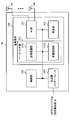
- FIG. 8 is a diagram showing an example of the configuration of the base station according to the embodiment.
- the base station 10 includes a control unit 110, a transmission / reception unit 120, a transmission / reception antenna 130, and a transmission line interface 140.
- the control unit 110, the transmission / reception unit 120, the transmission / reception antenna 130, and the transmission line interface 140 may each be provided with one or more.
- the functional blocks of the feature portion in the present embodiment are mainly shown, and it may be assumed that the base station 10 also has other functional blocks necessary for wireless communication. A part of the processing of each part described below may be omitted.
- the control unit 110 controls the entire base station 10.
- the control unit 110 can be composed of a controller, a control circuit, and the like described based on the common recognition in the technical field according to the present disclosure.
- the control unit 110 may control signal generation, scheduling (for example, resource allocation, mapping) and the like.
- the control unit 110 may control transmission / reception, measurement, and the like using the transmission / reception unit 120, the transmission / reception antenna 130, and the transmission line interface 140.
- the control unit 110 may generate data to be transmitted as a signal, control information, a sequence, and the like, and transfer the data to the transmission / reception unit 120.
- the control unit 110 may perform call processing (setting, release, etc.) of the communication channel, state management of the base station 10, management of radio resources, and the like.
- the transmission / reception unit 120 may include a baseband unit 121, a Radio Frequency (RF) unit 122, and a measurement unit 123.
- the baseband unit 121 may include a transmission processing unit 1211 and a reception processing unit 1212.
- the transmitter / receiver 120 includes a transmitter / receiver, an RF circuit, a baseband circuit, a filter, a phase shifter, a measurement circuit, a transmitter / receiver circuit, and the like, which are described based on common recognition in the technical fields according to the present disclosure. be able to.
- the transmission / reception unit 120 may be configured as an integrated transmission / reception unit, or may be composed of a transmission unit and a reception unit.
- the transmission unit may be composed of a transmission processing unit 1211 and an RF unit 122.
- the receiving unit may be composed of a receiving processing unit 1212, an RF unit 122, and a measuring unit 123.
- the transmitting / receiving antenna 130 can be composed of an antenna described based on common recognition in the technical field according to the present disclosure, for example, an array antenna.
- the transmission / reception unit 120 may transmit the above-mentioned downlink channel, synchronization signal, downlink reference signal, and the like.
- the transmission / reception unit 120 may receive the above-mentioned uplink channel, uplink reference signal, and the like.
- the transmission / reception unit 120 may form at least one of a transmission beam and a reception beam by using digital beamforming (for example, precoding), analog beamforming (for example, phase rotation), and the like.
- digital beamforming for example, precoding
- analog beamforming for example, phase rotation
- the transmission / reception unit 120 processes, for example, Packet Data Convergence Protocol (PDCP) layer processing and Radio Link Control (RLC) layer processing (for example, RLC) for data, control information, etc. acquired from control unit 110.
- PDCP Packet Data Convergence Protocol
- RLC Radio Link Control
- MAC Medium Access Control
- HARQ retransmission control HARQ retransmission control
- the transmission / reception unit 120 performs channel coding (may include error correction coding), modulation, mapping, filtering, and discrete Fourier transform (Discrete Fourier Transform (DFT)) for the bit string to be transmitted.
- the base band signal may be output by performing processing (if necessary), inverse fast Fourier transform (IFFT) processing, precoding, digital-analog conversion, and other transmission processing.
- IFFT inverse fast Fourier transform
- the transmission / reception unit 120 may perform modulation, filtering, amplification, etc. on the baseband signal to the radio frequency band, and transmit the signal in the radio frequency band via the transmission / reception antenna 130. ..
- the transmission / reception unit 120 may perform amplification, filtering, demodulation to a baseband signal, or the like on the signal in the radio frequency band received by the transmission / reception antenna 130.
- the transmission / reception unit 120 (reception processing unit 1212) performs analog-digital conversion, fast Fourier transform (FFT) processing, and inverse discrete Fourier transform (IDFT) on the acquired baseband signal. )) Processing (if necessary), filtering, demapping, demodulation, decoding (may include error correction decoding), MAC layer processing, RLC layer processing, PDCP layer processing, and other reception processing are applied. User data and the like may be acquired.
- FFT fast Fourier transform
- IDFT inverse discrete Fourier transform
- the transmission / reception unit 120 may perform measurement on the received signal.
- the measurement unit 123 may perform Radio Resource Management (RRM) measurement, Channel State Information (CSI) measurement, or the like based on the received signal.
- the measuring unit 123 has received power (for example, Reference Signal Received Power (RSRP)) and reception quality (for example, Reference Signal Received Quality (RSRQ), Signal to Interference plus Noise Ratio (SINR), Signal to Noise Ratio (SNR)).
- RSRP Reference Signal Received Power
- RSSQ Reference Signal Received Quality
- SINR Signal to Noise Ratio
- Signal strength for example, Received Signal Strength Indicator (RSSI)
- propagation path information for example, CSI
- the measurement result may be output to the control unit 110.
- the transmission line interface 140 transmits and receives signals (backhaul signaling) to and from devices included in the core network 30, other base stations 10, and the like, and provides user data (user plane data) and control plane for the user terminal 20. Data or the like may be acquired or transmitted.
- the transmitting unit and the receiving unit of the base station 10 in the present disclosure may be composed of at least one of the transmission / reception unit 120, the transmission / reception antenna 130, and the transmission line interface 140.
- control unit 110 may receive a phase tracking reference signal (Phase Tracking Reference Signal (PTRS)) for the uplink control channel (PUCCH) from the user terminal 20.
- PTRS Phase Tracking Reference Signal
- the control unit 110 may reduce (correct) the phase noise of the PUCCH based on the PTRS.
- FIG. 9 is a diagram showing an example of the configuration of the user terminal according to the embodiment.
- the user terminal 20 includes a control unit 210, a transmission / reception unit 220, and a transmission / reception antenna 230.
- the control unit 210, the transmission / reception unit 220, and the transmission / reception antenna 230 may each be provided with one or more.
- this example mainly shows the functional blocks of the feature portion in the present embodiment, and it may be assumed that the user terminal 20 also has other functional blocks necessary for wireless communication. A part of the processing of each part described below may be omitted.
- the control unit 210 controls the entire user terminal 20.
- the control unit 210 can be composed of a controller, a control circuit, and the like described based on the common recognition in the technical field according to the present disclosure.
- the control unit 210 may control signal generation, mapping, and the like.
- the control unit 210 may control transmission / reception, measurement, and the like using the transmission / reception unit 220 and the transmission / reception antenna 230.
- the control unit 210 may generate data to be transmitted as a signal, control information, a sequence, and the like, and transfer the data to the transmission / reception unit 220.
- the transmission / reception unit 220 may include a baseband unit 221 and an RF unit 222, and a measurement unit 223.
- the baseband unit 221 may include a transmission processing unit 2211 and a reception processing unit 2212.
- the transmitter / receiver 220 can be composed of a transmitter / receiver, an RF circuit, a baseband circuit, a filter, a phase shifter, a measurement circuit, a transmitter / receiver circuit, and the like, which are described based on the common recognition in the technical field according to the present disclosure.
- the transmission / reception unit 220 may be configured as an integrated transmission / reception unit, or may be composed of a transmission unit and a reception unit.
- the transmission unit may be composed of a transmission processing unit 2211 and an RF unit 222.
- the receiving unit may be composed of a receiving processing unit 2212, an RF unit 222, and a measuring unit 223.
- the transmitting / receiving antenna 230 can be composed of an antenna described based on common recognition in the technical field according to the present disclosure, for example, an array antenna.
- the transmission / reception unit 220 may receive the above-mentioned downlink channel, synchronization signal, downlink reference signal, and the like.
- the transmission / reception unit 220 may transmit the above-mentioned uplink channel, uplink reference signal, and the like.
- the transmission / reception unit 220 may form at least one of a transmission beam and a reception beam by using digital beamforming (for example, precoding), analog beamforming (for example, phase rotation), and the like.
- digital beamforming for example, precoding
- analog beamforming for example, phase rotation
- the transmission / reception unit 220 processes, for example, PDCP layer processing, RLC layer processing (for example, RLC retransmission control), and MAC layer processing (for example, for data, control information, etc. acquired from the control unit 210). , HARQ retransmission control), etc., to generate a bit string to be transmitted.
- the transmission / reception unit 220 (transmission processing unit 2211) performs channel coding (may include error correction coding), modulation, mapping, filtering processing, DFT processing (if necessary), and IFFT processing for the bit string to be transmitted. , Precoding, digital-to-analog conversion, and other transmission processing may be performed to output the baseband signal.
- Whether or not to apply the DFT process may be based on the transform precoding setting.
- the transmission / reception unit 220 transmission processing unit 2211 described above for transmitting a channel (for example, PUSCH) using the DFT-s-OFDM waveform when the transform precoding is enabled.
- the DFT process may be performed as the transmission process, and if not, the DFT process may not be performed as the transmission process.
- the transmission / reception unit 220 may perform modulation, filtering, amplification, etc. to the radio frequency band on the baseband signal, and transmit the signal in the radio frequency band via the transmission / reception antenna 230. ..
- the transmission / reception unit 220 may perform amplification, filtering, demodulation to a baseband signal, or the like on the signal in the radio frequency band received by the transmission / reception antenna 230.
- the transmission / reception unit 220 (reception processing unit 2212) performs analog-to-digital conversion, FFT processing, IDFT processing (if necessary), filtering processing, demapping, demodulation, and decoding (error correction) for the acquired baseband signal. Decoding may be included), MAC layer processing, RLC layer processing, PDCP layer processing, and other reception processing may be applied to acquire user data and the like.
- the transmission / reception unit 220 may perform measurement on the received signal.
- the measuring unit 223 may perform RRM measurement, CSI measurement, or the like based on the received signal.
- the measuring unit 223 may measure received power (for example, RSRP), reception quality (for example, RSRQ, SINR, SNR), signal strength (for example, RSSI), propagation path information (for example, CSI), and the like.
- the measurement result may be output to the control unit 210.
- the transmitter and receiver of the user terminal 20 in the present disclosure may be composed of at least one of the transmitter / receiver 220 and the transmitter / receiver antenna 230.
- the transmission / reception unit 220 may receive downlink control information (DCI) regarding the start position (for example, start block, start symbol, start RB, etc.) of the resource in at least one of the time domain and the frequency domain.
- the control unit 210 may cancel (for example, cancel) the uplink (UL) transmission using the resource based on the setting of the granularity of the start position and the DCI.
- the DCI may include at least one field of time domain resource allocation, number of iterations in the time domain (eg, number of iterations, iteration factor), frequency domain resource allocation, and frequency hopping flag (embodiment). 1-3).
- the time domain resource allocation field may indicate the resource by at least one of a bitmap and a value based on the start position and length (eg, RIV, SLIV, etc.) (Embodiment 1). ..
- the resource is repeated in the time domain, and the time domain resource allocation field may indicate the resource of the first repetition (Embodiment 1).
- the DCI has a cyclic redundancy check (CRC) scrambled by a different type of RNTI (eg UL_INT-RNTI) than the radio network temporary identifier (eg INT-RNTI) used for downlink (DL) preemption instructions. It may be (Embodiment 3).
- CRC cyclic redundancy check
- the DCI may be commonly transmitted to a group of terminals (eg, the DCI may be carried by a GC-PDCCH, the DCI may be a group common DCI) (Embodiments 1-3). ..
- each functional block may be realized by using one device that is physically or logically connected, or directly or indirectly (for example, by using two or more physically or logically separated devices). , Wired, wireless, etc.) and may be realized using these plurality of devices.
- the functional block may be realized by combining the software with the one device or the plurality of devices.
- the functions include judgment, decision, judgment, calculation, calculation, processing, derivation, investigation, search, confirmation, reception, transmission, output, access, solution, selection, selection, establishment, comparison, assumption, expectation, and deemed. , Broadcasting, notifying, communicating, forwarding, configuring, reconfiguring, allocating, mapping, assigning, etc.
- a functional block that functions transmission may be referred to as a transmitting unit (transmitting unit), a transmitter (transmitter), or the like.
- the method of realizing each of them is not particularly limited.
- the base station, user terminal, and the like in one embodiment of the present disclosure may function as a computer that processes the wireless communication method of the present disclosure.
- FIG. 10 is a diagram showing an example of the hardware configuration of the base station and the user terminal according to the embodiment.
- the base station 10 and the user terminal 20 described above may be physically configured as a computer device including a processor 1001, a memory 1002, a storage 1003, a communication device 1004, an input device 1005, an output device 1006, a bus 1007, and the like. ..
- the hardware configuration of the base station 10 and the user terminal 20 may be configured to include one or more of the devices shown in the figure, or may be configured not to include some of the devices.
- processor 1001 may be a plurality of processors. Further, the processing may be executed by one processor, or the processing may be executed simultaneously, sequentially, or by using other methods by two or more processors.
- the processor 1001 may be mounted by one or more chips.
- the processor 1001 For each function of the base station 10 and the user terminal 20, for example, by loading predetermined software (program) on hardware such as the processor 1001 and the memory 1002, the processor 1001 performs an operation and communicates via the communication device 1004. It is realized by controlling at least one of reading and writing of data in the memory 1002 and the storage 1003.
- predetermined software program
- the processor 1001 operates, for example, an operating system to control the entire computer.
- the processor 1001 may be configured by a central processing unit (CPU) including an interface with peripheral devices, a control device, an arithmetic unit, registers, and the like.
- CPU central processing unit
- control unit 110 210
- transmission / reception unit 120 220
- the like may be realized by the processor 1001.
- the processor 1001 reads a program (program code), a software module, data, etc. from at least one of the storage 1003 and the communication device 1004 into the memory 1002, and executes various processes according to these.
- a program program code
- the control unit 110 may be realized by a control program stored in the memory 1002 and operating in the processor 1001, and may be realized in the same manner for other functional blocks.
- the memory 1002 is a computer-readable recording medium, for example, at least a Read Only Memory (ROM), an Erasable Programmable ROM (EPROM), an Electrically EPROM (EPROM), a Random Access Memory (RAM), or any other suitable storage medium. It may be composed of one.
- the memory 1002 may be referred to as a register, a cache, a main memory (main storage device), or the like.
- the memory 1002 can store a program (program code), a software module, or the like that can be executed to implement the wireless communication method according to the embodiment of the present disclosure.
- the storage 1003 is a computer-readable recording medium, for example, a flexible disk, a floppy (registered trademark) disk, an optical magnetic disk (for example, a compact disc (Compact Disc ROM (CD-ROM)), a digital versatile disk, etc.). At least one of Blu-ray® disks, removable disks, hard disk drives, smart cards, flash memory devices (eg cards, sticks, key drives), magnetic stripes, databases, servers, and other suitable storage media. It may be composed of.
- the storage 1003 may be referred to as an auxiliary storage device.
- the communication device 1004 is hardware (transmission / reception device) for communicating between computers via at least one of a wired network and a wireless network, and is also referred to as, for example, a network device, a network controller, a network card, a communication module, or the like.
- the communication device 1004 includes, for example, a high frequency switch, a duplexer, a filter, a frequency synthesizer, etc. in order to realize at least one of frequency division duplex (Frequency Division Duplex (FDD)) and time division duplex (Time Division Duplex (TDD)). It may be configured to include.
- the transmission / reception unit 120 (220), the transmission / reception antenna 130 (230), and the like described above may be realized by the communication device 1004.
- the transmission / reception unit 120 (220) may be physically or logically separated from the transmission unit 120a (220a) and the reception unit 120b (220b).
- the input device 1005 is an input device (for example, a keyboard, a mouse, a microphone, a switch, a button, a sensor, etc.) that receives an input from the outside.
- the output device 1006 is an output device (for example, a display, a speaker, a Light Emitting Diode (LED) lamp, etc.) that outputs to the outside.
- the input device 1005 and the output device 1006 may have an integrated configuration (for example, a touch panel).
- each device such as the processor 1001 and the memory 1002 is connected by the bus 1007 for communicating information.
- the bus 1007 may be configured by using a single bus, or may be configured by using a different bus for each device.
- the base station 10 and the user terminal 20 include a microprocessor, a digital signal processor (Digital Signal Processor (DSP)), an Application Specific Integrated Circuit (ASIC), a Programmable Logic Device (PLD), a Field Programmable Gate Array (FPGA), and the like. It may be configured to include hardware, and a part or all of each functional block may be realized by using the hardware. For example, processor 1001 may be implemented using at least one of these hardware.
- DSP Digital Signal Processor
- ASIC Application Specific Integrated Circuit
- PLD Programmable Logic Device
- FPGA Field Programmable Gate Array
- the wireless frame may be composed of one or more periods (frames) in the time domain.
- Each of the one or more periods (frames) constituting the wireless frame may be referred to as a subframe.
- the subframe may be composed of one or more slots in the time domain.
- the subframe may have a fixed time length (eg, 1 ms) that is independent of numerology.
- the numerology may be a communication parameter applied to at least one of transmission and reception of a signal or channel.
- Pneumerology includes, for example, subcarrier spacing (SubCarrier Spacing (SCS)), bandwidth, symbol length, cyclic prefix length, transmission time interval (Transmission Time Interval (TTI)), number of symbols per TTI, and wireless frame configuration.
- SCS subcarrier Spacing
- TTI Transmission Time Interval
- a specific filtering process performed by the transmitter / receiver in the frequency domain, a specific windowing process performed by the transmitter / receiver in the time domain, and the like may be indicated.
- the slot may be composed of one or more symbols in the time domain (Orthogonal Frequency Division Multiple Access (OFDMA) symbol, Single Carrier Frequency Division Multiple Access (SC-FDMA) symbol, etc.). Further, the slot may be a time unit based on numerology.
- OFDMA Orthogonal Frequency Division Multiple Access
- SC-FDMA Single Carrier Frequency Division Multiple Access
- the slot may include a plurality of mini slots. Each minislot may consist of one or more symbols in the time domain. Further, the mini slot may be called a sub slot. A minislot may consist of a smaller number of symbols than the slot.
- a PDSCH (or PUSCH) transmitted in time units larger than the minislot may be referred to as a PDSCH (PUSCH) mapping type A.
- the PDSCH (or PUSCH) transmitted using the minislot may be referred to as PDSCH (PUSCH) mapping type B.
- the wireless frame, subframe, slot, mini slot and symbol all represent the time unit when transmitting a signal.
- the radio frame, subframe, slot, minislot and symbol may have different names corresponding to each.
- the time units such as frames, subframes, slots, mini slots, and symbols in the present disclosure may be read as each other.
- one subframe may be called TTI
- a plurality of consecutive subframes may be called TTI
- one slot or one minislot may be called TTI. That is, at least one of the subframe and TTI may be a subframe (1 ms) in existing LTE, a period shorter than 1 ms (eg, 1-13 symbols), or a period longer than 1 ms. It may be.
- the unit representing TTI may be called a slot, a mini slot, or the like instead of a subframe.
- TTI refers to, for example, the minimum time unit of scheduling in wireless communication.
- the base station schedules each user terminal to allocate radio resources (frequency bandwidth that can be used in each user terminal, transmission power, etc.) in TTI units.
- the definition of TTI is not limited to this.
- the TTI may be a transmission time unit such as a channel-encoded data packet (transport block), a code block, or a code word, or may be a processing unit such as scheduling or link adaptation.
- the time interval for example, the number of symbols
- the transport block, code block, code word, etc. may be shorter than the TTI.
- one or more TTIs may be the minimum time unit for scheduling. Further, the number of slots (number of mini-slots) constituting the minimum time unit of the scheduling may be controlled.
- a TTI having a time length of 1 ms may be referred to as a normal TTI (TTI in 3GPP Rel. 8-12), a normal TTI, a long TTI, a normal subframe, a normal subframe, a long subframe, a slot, or the like.
- TTIs shorter than normal TTIs may be referred to as shortened TTIs, short TTIs, partial TTIs (partial or fractional TTIs), shortened subframes, short subframes, minislots, subslots, slots, and the like.
- the long TTI (for example, normal TTI, subframe, etc.) may be read as a TTI having a time length of more than 1 ms, and the short TTI (for example, shortened TTI, etc.) is less than the TTI length of the long TTI and 1 ms. It may be read as a TTI having the above TTI length.
- a resource block is a resource allocation unit in the time domain and the frequency domain, and may include one or a plurality of continuous subcarriers in the frequency domain.
- the number of subcarriers contained in the RB may be the same regardless of the numerology, and may be, for example, 12.
- the number of subcarriers contained in the RB may be determined based on numerology.
- the RB may include one or more symbols in the time domain, and may have a length of 1 slot, 1 mini slot, 1 subframe or 1 TTI.
- Each 1TTI, 1 subframe, etc. may be composed of one or a plurality of resource blocks.
- One or more RBs are a physical resource block (Physical RB (PRB)), a sub-carrier group (Sub-Carrier Group (SCG)), a resource element group (Resource Element Group (REG)), a PRB pair, and an RB. It may be called a pair or the like.
- Physical RB Physical RB (PRB)
- SCG sub-carrier Group
- REG resource element group
- the resource block may be composed of one or a plurality of resource elements (Resource Element (RE)).
- RE Resource Element
- 1RE may be a radio resource area of 1 subcarrier and 1 symbol.
- Bandwidth Part (which may also be called partial bandwidth, etc.) represents a subset of consecutive common resource blocks (RBs) for a neurology in a carrier. May be good.
- the common RB may be specified by the index of the RB with respect to the common reference point of the carrier.
- PRBs may be defined in a BWP and numbered within that BWP.
- the BWP may include UL BWP (BWP for UL) and DL BWP (BWP for DL).
- BWP UL BWP
- BWP for DL DL BWP
- One or more BWPs may be set in one carrier for the UE.
- At least one of the configured BWPs may be active, and the UE may not expect to send or receive a given signal / channel outside the active BWP.
- “cell”, “carrier” and the like in this disclosure may be read as “BWP”.
- the above-mentioned structures such as wireless frames, subframes, slots, mini slots, and symbols are merely examples.
- the number of subframes contained in a wireless frame the number of slots per subframe or wireless frame, the number of minislots contained within a slot, the number of symbols and RBs contained in a slot or minislot, included in the RB.
- the number of subcarriers, the number of symbols in the TTI, the symbol length, the cyclic prefix (CP) length, and other configurations can be changed in various ways.
- the information, parameters, etc. described in the present disclosure may be expressed using absolute values, relative values from predetermined values, or using other corresponding information. It may be represented. For example, radio resources may be indicated by a given index.
- the information, signals, etc. described in this disclosure may be represented using any of a variety of different techniques.
- data, instructions, commands, information, signals, bits, symbols, chips, etc. that may be referred to throughout the above description are voltages, currents, electromagnetic waves, magnetic fields or magnetic particles, light fields or photons, or any of these. It may be represented by a combination of.
- information, signals, etc. can be output from the upper layer to the lower layer and from the lower layer to at least one of the upper layers.
- Information, signals, etc. may be input / output via a plurality of network nodes.
- the input / output information, signals, etc. may be stored in a specific location (for example, memory) or may be managed using a management table. Input / output information, signals, etc. can be overwritten, updated, or added. The output information, signals, etc. may be deleted. The input information, signals, etc. may be transmitted to other devices.
- the notification of information is not limited to the mode / embodiment described in the present disclosure, and may be performed by using another method.
- the notification of information in the present disclosure includes physical layer signaling (for example, downlink control information (DCI)), uplink control information (Uplink Control Information (UCI))), and higher layer signaling (for example, Radio Resource Control). (RRC) signaling, broadcast information (master information block (MIB), system information block (SIB), etc.), medium access control (MAC) signaling), other signals or combinations thereof May be carried out by.
- DCI downlink control information
- UCI Uplink Control Information
- RRC Radio Resource Control
- MIB master information block
- SIB system information block
- MAC medium access control
- the physical layer signaling may be referred to as Layer 1 / Layer 2 (L1 / L2) control information (L1 / L2 control signal), L1 control information (L1 control signal), and the like.
- the RRC signaling may be called an RRC message, and may be, for example, an RRC connection setup (RRC Connection Setup) message, an RRC connection reconfiguration (RRC Connection Reconfiguration) message, or the like.
- MAC signaling may be notified using, for example, a MAC control element (MAC Control Element (CE)).
- CE MAC Control Element
- the notification of predetermined information is not limited to the explicit notification, but implicitly (for example, by not notifying the predetermined information or another information). May be done (by notification of).
- the determination may be made by a value represented by 1 bit (0 or 1), or by a boolean value represented by true or false. , May be done by numerical comparison (eg, comparison with a given value).
- Software is an instruction, instruction set, code, code segment, program code, program, subprogram, software module, whether called software, firmware, middleware, microcode, hardware description language, or another name.
- Applications, software applications, software packages, routines, subroutines, objects, executables, execution threads, procedures, features, etc. should be broadly interpreted to mean.
- software, instructions, information, etc. may be transmitted and received via a transmission medium.
- a transmission medium For example, a website where software uses at least one of wired technology (coaxial cable, fiber optic cable, twist pair, digital subscriber line (DSL), etc.) and wireless technology (infrared, microwave, etc.).
- wired technology coaxial cable, fiber optic cable, twist pair, digital subscriber line (DSL), etc.
- wireless technology infrared, microwave, etc.
- Network may mean a device (eg, a base station) included in the network.
- precoding "precoding weight”
- QCL Quality of Co-Co-Location
- TCI state Transmission Configuration Indication state
- space "Spatial relation”, “spatial domain filter”, “transmission power”, “phase rotation”, "antenna port”, “antenna port group”, “layer”, “number of layers”
- Terms such as “rank”, “resource”, “resource set”, “resource group”, “beam”, “beam width”, “beam angle”, "antenna”, “antenna element", “panel” are compatible.
- Base station BS
- radio base station fixed station
- NodeB NodeB
- eNB eNodeB
- gNB gNodeB
- Access point "Transmission point (Transmission Point (TP))
- RP Reception point
- TRP Transmission / Reception Point
- Panel , "Cell”, “sector”, “cell group”, “carrier”, “component carrier” and the like
- Base stations are sometimes referred to by terms such as macrocells, small cells, femtocells, and picocells.
- the base station can accommodate one or more (for example, three) cells.
- a base station accommodates multiple cells, the entire coverage area of the base station can be divided into multiple smaller areas, each smaller area being a base station subsystem (eg, a small indoor base station (Remote Radio)).
- Communication services can also be provided by Head (RRH))).
- RRH Head
- the term "cell” or “sector” refers to part or all of the coverage area of at least one of the base stations and base station subsystems that provide communication services in this coverage.
- MS mobile station
- UE user equipment
- terminal terminal
- Mobile stations include subscriber stations, mobile units, subscriber units, wireless units, remote units, mobile devices, wireless devices, wireless communication devices, remote devices, mobile subscriber stations, access terminals, mobile terminals, wireless terminals, remote terminals. , Handset, user agent, mobile client, client or some other suitable term.
- At least one of the base station and the mobile station may be called a transmitting device, a receiving device, a wireless communication device, or the like.
- At least one of the base station and the mobile station may be a device mounted on the mobile body, the mobile body itself, or the like.
- the moving body may be a vehicle (eg, car, airplane, etc.), an unmanned moving body (eg, drone, self-driving car, etc.), or a robot (manned or unmanned). ) May be.
- at least one of the base station and the mobile station includes a device that does not necessarily move during communication operation.
- at least one of the base station and the mobile station may be an Internet of Things (IoT) device such as a sensor.
- IoT Internet of Things
- the base station in the present disclosure may be read by the user terminal.
- communication between a base station and a user terminal is replaced with communication between a plurality of user terminals (for example, it may be called Device-to-Device (D2D), Vehicle-to-Everything (V2X), etc.).
- D2D Device-to-Device
- V2X Vehicle-to-Everything
- Each aspect / embodiment of the present disclosure may be applied to the configuration.
- the user terminal 20 may have the function of the base station 10 described above.
- words such as "up” and “down” may be read as words corresponding to communication between terminals (for example, "side”).
- the uplink, downlink, and the like may be read as side channels.
- the user terminal in the present disclosure may be read as a base station.
- the base station 10 may have the functions of the user terminal 20 described above.
- the operation performed by the base station may be performed by its upper node (upper node) in some cases.
- various operations performed for communication with a terminal are performed by the base station and one or more network nodes other than the base station (for example,).
- Mobility Management Entity (MME), Serving-Gateway (S-GW), etc. can be considered, but it is not limited to these), or it is clear that it can be performed by a combination thereof.
- each aspect / embodiment described in the present disclosure may be used alone, in combination, or switched with execution.
- the order of the processing procedures, sequences, flowcharts, etc. of each aspect / embodiment described in the present disclosure may be changed as long as there is no contradiction.
- the methods described in the present disclosure present elements of various steps using exemplary order, and are not limited to the particular order presented.
- LTE Long Term Evolution
- LTE-A LTE-Advanced
- SUPER 3G IMT-Advanced
- 4G 4th generation mobile communication system
- 5G 5th generation mobile communication system
- Future Radio Access FAA
- New-Radio Access Technology RAT
- NR New Radio
- NX New radio access
- Future generation radio access FX
- GSM Global System for Mobile communications
- CDMA2000 Code Division Multiple Access
- UMB Ultra Mobile Broadband
- IEEE 802.11 Wi-Fi (registered trademark)
- IEEE 802.16 WiMAX (registered trademark)
- a plurality of systems may be applied in combination (for example, a combination of LTE or LTE-A and 5G).
- references to elements using designations such as “first”, “second”, etc. as used in this disclosure does not generally limit the quantity or order of those elements. These designations can be used in the present disclosure as a convenient way to distinguish between two or more elements. Thus, references to the first and second elements do not mean that only two elements can be adopted or that the first element must somehow precede the second element.
- determining used in this disclosure may include a wide variety of actions.
- judgment (decision) means judgment (judging), calculation (calculating), calculation (computing), processing (processing), derivation (deriving), investigation (investigating), search (looking up, search, inquiry) ( For example, searching in a table, database or another data structure), ascertaining, etc. may be considered to be "judgment”.
- judgment (decision) means receiving (for example, receiving information), transmitting (for example, transmitting information), input (input), output (output), access (for example). It may be regarded as “judgment (decision)" of "accessing” (for example, accessing data in memory).
- judgment (decision) is regarded as “judgment (decision)” of solving, selecting, choosing, establishing, comparing, and the like. May be good. That is, “judgment (decision)” may be regarded as “judgment (decision)” of some action.
- the "maximum transmission power" described in the present disclosure may mean the maximum value of the transmission power, may mean the nominal UE maximum transmit power, or may mean the rated maximum transmission power (the). It may mean rated UE maximum transmit power).
- connection are any direct or indirect connection or connection between two or more elements. Means, and can include the presence of one or more intermediate elements between two elements that are “connected” or “joined” to each other.
- the connection or connection between the elements may be physical, logical, or a combination thereof. For example, "connection” may be read as "access”.
- the radio frequency domain microwaves. It can be considered to be “connected” or “coupled” to each other using frequency, electromagnetic energy having wavelengths in the light (both visible and invisible) regions, and the like.
- the term "A and B are different” may mean “A and B are different from each other”.
- the term may mean that "A and B are different from C”.
- Terms such as “separate” and “combined” may be interpreted in the same way as “different”.
Landscapes
- Engineering & Computer Science (AREA)
- Computer Networks & Wireless Communication (AREA)
- Signal Processing (AREA)
- Mobile Radio Communication Systems (AREA)
Priority Applications (6)
| Application Number | Priority Date | Filing Date | Title |
|---|---|---|---|
| EP19938585.7A EP4007417A4 (en) | 2019-07-23 | 2019-07-23 | TERMINAL AND WIRELESS COMMUNICATION METHOD |
| CN201980100454.7A CN114402688A (zh) | 2019-07-23 | 2019-07-23 | 终端以及无线通信方法 |
| US17/628,707 US20220272739A1 (en) | 2019-07-23 | 2019-07-23 | Terminal and radio communication method |
| MX2022000887A MX2022000887A (es) | 2019-07-23 | 2019-07-23 | Terminal y metodo de radiocomunicacion. |
| JP2021534460A JP7439092B2 (ja) | 2019-07-23 | 2019-07-23 | 端末、無線通信方法及びシステム |
| PCT/JP2019/028875 WO2021014576A1 (ja) | 2019-07-23 | 2019-07-23 | 端末及び無線通信方法 |
Applications Claiming Priority (1)
| Application Number | Priority Date | Filing Date | Title |
|---|---|---|---|
| PCT/JP2019/028875 WO2021014576A1 (ja) | 2019-07-23 | 2019-07-23 | 端末及び無線通信方法 |
Publications (1)
| Publication Number | Publication Date |
|---|---|
| WO2021014576A1 true WO2021014576A1 (ja) | 2021-01-28 |
Family
ID=74193553
Family Applications (1)
| Application Number | Title | Priority Date | Filing Date |
|---|---|---|---|
| PCT/JP2019/028875 Ceased WO2021014576A1 (ja) | 2019-07-23 | 2019-07-23 | 端末及び無線通信方法 |
Country Status (6)
| Country | Link |
|---|---|
| US (1) | US20220272739A1 (https=) |
| EP (1) | EP4007417A4 (https=) |
| JP (1) | JP7439092B2 (https=) |
| CN (1) | CN114402688A (https=) |
| MX (1) | MX2022000887A (https=) |
| WO (1) | WO2021014576A1 (https=) |
Cited By (7)
| Publication number | Priority date | Publication date | Assignee | Title |
|---|---|---|---|---|
| US11523414B2 (en) | 2018-01-13 | 2022-12-06 | Wilus Institute Of Standards And Technology Inc. | Channel multiplexing method and multiplexed channel transmission method for wireless communication system and device using same |
| US11601966B2 (en) | 2019-10-07 | 2023-03-07 | Wilus Institute Of Standards And Technology Inc. | Method, device, and system for cancelling uplink transmission in wireless communication system |
| CN115915434A (zh) * | 2021-08-06 | 2023-04-04 | 华为技术有限公司 | 一种确定时域资源的方法和装置 |
| WO2025202272A1 (en) | 2024-03-28 | 2025-10-02 | Societe Des Produits Nestle S.A. | Container for beverage or foodstuff preparation machine |
| WO2025202268A1 (en) | 2024-03-28 | 2025-10-02 | Societe Des Produits Nestle S.A. | Container for beverage or foodstuff preparation machine |
| WO2025202271A1 (en) | 2024-03-28 | 2025-10-02 | Societe Des Produits Nestle S.A. | Container for beverage or foodstuff preparation machine |
| EP4514028A4 (en) * | 2022-04-22 | 2026-02-25 | Ntt Docomo Inc | TERMINAL, BASE STATION AND COMMUNICATION METHOD |
Families Citing this family (6)
| Publication number | Priority date | Publication date | Assignee | Title |
|---|---|---|---|---|
| CN111835483B (zh) * | 2019-08-08 | 2022-07-08 | 维沃移动通信有限公司 | 一种信息传输方法及电子设备 |
| EP4128971B1 (en) * | 2020-03-23 | 2025-07-30 | Qualcomm Incorporated | Uplink cancelation indication |
| US12082180B2 (en) * | 2020-05-07 | 2024-09-03 | Qualcomm Incorporated | Resource identification for uplink scheduled transmission after cancellation indication receipt |
| US20240023093A1 (en) * | 2021-01-25 | 2024-01-18 | Qualcomm Incorporated | Ulci enhancement for reduced capability ue |
| US11956732B2 (en) * | 2021-09-28 | 2024-04-09 | Qualcomm Incorporated | Autonomous physical uplink shared channel repetition cancellation for energy-limited devices |
| US20250096954A1 (en) * | 2023-09-20 | 2025-03-20 | Qualcomm Incorporated | Multiple physical uplink shared channel configuration with repetition |
Citations (1)
| Publication number | Priority date | Publication date | Assignee | Title |
|---|---|---|---|---|
| WO2018128970A1 (en) * | 2017-01-06 | 2018-07-12 | Sharp Laboratories Of America, Inc. | Signaling, procedures, user equipment and base stations for uplink ultra reliable low latency communications |
Family Cites Families (7)
| Publication number | Priority date | Publication date | Assignee | Title |
|---|---|---|---|---|
| EP2795981A1 (en) * | 2011-12-22 | 2014-10-29 | Interdigital Patent Holdings, Inc. | Control signaling in lte carrier aggregation |
| US10932278B2 (en) * | 2017-03-20 | 2021-02-23 | Convida Wireless, Llc | Scheduling and control in new radio using preemption indication |
| WO2019087359A1 (ja) * | 2017-11-02 | 2019-05-09 | 株式会社Nttドコモ | ユーザ端末及び無線通信方法 |
| FI4113892T3 (fi) * | 2018-01-13 | 2024-01-31 | Wilus Inst Standards & Tech Inc | Kanavan multipleksointia langattomassa tietoliikennejärjestelmässä käyttävä laite |
| US11357017B2 (en) * | 2019-01-11 | 2022-06-07 | Lenovo (Singapore) Pte. Ltd. | Method and apparatus for transmitting a high priority uplink transmission |
| WO2020206099A1 (en) * | 2019-04-02 | 2020-10-08 | Apple Inc. | System and method of downlink control channel signaling for uplink coexistence of multiple service types |
| US11350453B2 (en) * | 2019-07-18 | 2022-05-31 | Samsung Electronics Co., Ltd. | System and method for performing transmission cancellation indication monitoring |
-
2019
- 2019-07-23 MX MX2022000887A patent/MX2022000887A/es unknown
- 2019-07-23 EP EP19938585.7A patent/EP4007417A4/en active Pending
- 2019-07-23 WO PCT/JP2019/028875 patent/WO2021014576A1/ja not_active Ceased
- 2019-07-23 CN CN201980100454.7A patent/CN114402688A/zh active Pending
- 2019-07-23 JP JP2021534460A patent/JP7439092B2/ja active Active
- 2019-07-23 US US17/628,707 patent/US20220272739A1/en not_active Abandoned
Patent Citations (1)
| Publication number | Priority date | Publication date | Assignee | Title |
|---|---|---|---|---|
| WO2018128970A1 (en) * | 2017-01-06 | 2018-07-12 | Sharp Laboratories Of America, Inc. | Signaling, procedures, user equipment and base stations for uplink ultra reliable low latency communications |
Non-Patent Citations (3)
| Title |
|---|
| "Evolved Universal Terrestrial Radio Access (E-UTRA) and Evolved Universal Terrestrial Radio Access Network (E-UTRAN); Overall description; Stage 2 (Release 8", 3GPP TS 36.300, April 2010 (2010-04-01) |
| 3GPP TSG RAN WG1 #97, R1-1907819, 17 May 2019 (2019-05-17), XP051740092 * |
| See also references of EP4007417A4 |
Cited By (11)
| Publication number | Priority date | Publication date | Assignee | Title |
|---|---|---|---|---|
| US11523414B2 (en) | 2018-01-13 | 2022-12-06 | Wilus Institute Of Standards And Technology Inc. | Channel multiplexing method and multiplexed channel transmission method for wireless communication system and device using same |
| US11950226B2 (en) | 2018-01-13 | 2024-04-02 | Wilus Institute Of Standards And Technology Inc. | Channel multiplexing method and multiplexed channel transmission method for wireless communication system and device using same |
| US11956774B2 (en) | 2018-01-13 | 2024-04-09 | Wilus Institute Of Standards And Technology Inc. | Channel multiplexing method and multiplexed channel transmission method for wireless communication system and device using same |
| US11601966B2 (en) | 2019-10-07 | 2023-03-07 | Wilus Institute Of Standards And Technology Inc. | Method, device, and system for cancelling uplink transmission in wireless communication system |
| US12114329B2 (en) | 2019-10-07 | 2024-10-08 | Wilus Institute Of Standards And Technology Inc. | Method, device, and system for cancelling uplink transmission in wireless communication system |
| US12302351B2 (en) | 2019-10-07 | 2025-05-13 | Wilus Institute Of Standards And Technology Inc. | Method, device, and system for cancelling uplink transmission in wireless communication system |
| CN115915434A (zh) * | 2021-08-06 | 2023-04-04 | 华为技术有限公司 | 一种确定时域资源的方法和装置 |
| EP4514028A4 (en) * | 2022-04-22 | 2026-02-25 | Ntt Docomo Inc | TERMINAL, BASE STATION AND COMMUNICATION METHOD |
| WO2025202272A1 (en) | 2024-03-28 | 2025-10-02 | Societe Des Produits Nestle S.A. | Container for beverage or foodstuff preparation machine |
| WO2025202268A1 (en) | 2024-03-28 | 2025-10-02 | Societe Des Produits Nestle S.A. | Container for beverage or foodstuff preparation machine |
| WO2025202271A1 (en) | 2024-03-28 | 2025-10-02 | Societe Des Produits Nestle S.A. | Container for beverage or foodstuff preparation machine |
Also Published As
| Publication number | Publication date |
|---|---|
| EP4007417A4 (en) | 2023-03-22 |
| JP7439092B2 (ja) | 2024-02-27 |
| EP4007417A1 (en) | 2022-06-01 |
| US20220272739A1 (en) | 2022-08-25 |
| MX2022000887A (es) | 2022-02-11 |
| CN114402688A (zh) | 2022-04-26 |
| JPWO2021014576A1 (https=) | 2021-01-28 |
Similar Documents
| Publication | Publication Date | Title |
|---|---|---|
| JP7439092B2 (ja) | 端末、無線通信方法及びシステム | |
| JP7273072B2 (ja) | 端末、無線通信方法及びシステム | |
| JP2023171931A (ja) | 端末、無線通信方法、基地局及びシステム | |
| JPWO2020065870A1 (ja) | 端末、無線通信方法、基地局及びシステム | |
| JP7273071B2 (ja) | 端末、無線通信方法、基地局及びシステム | |
| JPWO2020090093A1 (ja) | ユーザ端末 | |
| JPWO2020066025A1 (ja) | 端末、無線通信方法、基地局及びシステム | |
| JP7216221B2 (ja) | 端末、無線通信方法、基地局及びシステム | |
| JP7335349B2 (ja) | 端末、無線通信方法、基地局及びシステム | |
| JPWO2020066022A1 (ja) | 端末、無線通信方法、基地局及びシステム | |
| JP7375017B2 (ja) | 端末、無線通信方法、基地局及びシステム | |
| JP7413414B2 (ja) | 端末、無線通信方法、基地局及びシステム | |
| WO2020217514A1 (ja) | ユーザ端末及び無線通信方法 | |
| WO2020188644A1 (ja) | ユーザ端末及び無線通信方法 | |
| WO2020255263A1 (ja) | 端末及び無線通信方法 | |
| WO2022153459A1 (ja) | 端末、無線通信方法及び基地局 | |
| WO2020202478A1 (ja) | ユーザ端末及び無線通信方法 | |
| WO2021090409A1 (ja) | 端末及び無線通信方法 | |
| JP7526779B2 (ja) | 端末、無線通信方法、基地局及びシステム | |
| WO2020188821A1 (ja) | ユーザ端末及び無線通信方法 | |
| WO2021161396A1 (ja) | 端末、無線通信方法及び基地局 | |
| JPWO2020153209A1 (ja) | ユーザ端末及び無線通信方法 | |
| WO2021024435A1 (ja) | 端末及び無線通信方法 | |
| WO2020202477A1 (ja) | ユーザ端末及び無線通信方法 | |
| JP7330597B2 (ja) | 端末、無線通信方法及びシステム |
Legal Events
| Date | Code | Title | Description |
|---|---|---|---|
| 121 | Ep: the epo has been informed by wipo that ep was designated in this application |
Ref document number: 19938585 Country of ref document: EP Kind code of ref document: A1 |
|
| ENP | Entry into the national phase |
Ref document number: 2021534460 Country of ref document: JP Kind code of ref document: A |
|
| NENP | Non-entry into the national phase |
Ref country code: DE |
|
| ENP | Entry into the national phase |
Ref document number: 2019938585 Country of ref document: EP Effective date: 20220223 |