WO2021010354A1 - 皮下埋込型ポート - Google Patents
皮下埋込型ポート Download PDFInfo
- Publication number
- WO2021010354A1 WO2021010354A1 PCT/JP2020/027154 JP2020027154W WO2021010354A1 WO 2021010354 A1 WO2021010354 A1 WO 2021010354A1 JP 2020027154 W JP2020027154 W JP 2020027154W WO 2021010354 A1 WO2021010354 A1 WO 2021010354A1
- Authority
- WO
- WIPO (PCT)
- Prior art keywords
- port
- pair
- end side
- connection
- housing member
- Prior art date
- Legal status (The legal status is an assumption and is not a legal conclusion. Google has not performed a legal analysis and makes no representation as to the accuracy of the status listed.)
- Ceased
Links
Images


Classifications
-
- A—HUMAN NECESSITIES
- A61—MEDICAL OR VETERINARY SCIENCE; HYGIENE
- A61M—DEVICES FOR INTRODUCING MEDIA INTO, OR ONTO, THE BODY; DEVICES FOR TRANSDUCING BODY MEDIA OR FOR TAKING MEDIA FROM THE BODY; DEVICES FOR PRODUCING OR ENDING SLEEP OR STUPOR
- A61M37/00—Other apparatus for introducing media into the body; Percutany, i.e. introducing medicines into the body by diffusion through the skin
-
- A—HUMAN NECESSITIES
- A61—MEDICAL OR VETERINARY SCIENCE; HYGIENE
- A61M—DEVICES FOR INTRODUCING MEDIA INTO, OR ONTO, THE BODY; DEVICES FOR TRANSDUCING BODY MEDIA OR FOR TAKING MEDIA FROM THE BODY; DEVICES FOR PRODUCING OR ENDING SLEEP OR STUPOR
- A61M39/00—Tubes, tube connectors, tube couplings, valves, access sites or the like, specially adapted for medical use
- A61M39/10—Tube connectors; Tube couplings
Definitions
- the present invention relates to a subcutaneously implantable port that is embedded under the skin of a patient and used in the medical field when injecting a drug solution or the like into the body, and that can prevent the catheter from coming off. It is a thing.
- a port for injecting the drug solution should be buried under the skin of the patient in order to reduce the burden of repeated punctures into the human body. Will be considered.
- the opening of the housing is closed with an elastic lid, as in the case of the subcutaneous implantable port shown in Japanese Patent Application Laid-Open No. 2012-070986 (Patent Document 1). It has a structure in which a cavity for storing chemicals is formed. Then, the drug solution injected into the lumen by a needle that penetrates the skin and punctures the elastic lid is passed through a catheter through a blood vessel or the like from a connection port that constitutes a flow path for the drug solution to flow out provided on the outer peripheral portion of the housing. It is designed to be guided into the internal lumen of the body and injected.
- the catheter is fitted and connected to the connection port in an extrapolated state.
- the catheter is cut by a doctor to an appropriate length according to the physique of the patient and then attached to the connection port.
- the catheter removed from the connection port may be attached to the connection port after being adjusted in length again. Therefore, it is desirable that the catheter be detachably attached to the connection port without gluing or the like.
- Subcutaneous implantable port is a device that is indwelled for a long period of time. As a result of long-term indwelling, the tip and middle part of the catheter may stick to the living body, and if the site where the subcutaneous implantable port is embedded is moved violently in this state, the catheter will be connected from the subcutaneous implantable port. May come off.
- An object of the present invention is to provide a subcutaneously implantable port having a novel structure capable of stably maintaining a connection state with respect to a catheter connection port.
- the first aspect is subcutaneous implantation with a housing provided with a cavity for storing drug fluid that is closed with an elastic lid and provided with a connection port that communicates with the cavity and is inserted and connected to a catheter. It is a mold port and has a sleeve-shaped connecting cap that is extrapolated to the catheter and sandwiches the connecting end of the catheter in the radial direction with the connecting port, and the connecting cap is attached to the housing. It has a locking portion that can be locked.
- connection cap is positioned in the extraction direction with respect to the connection port by locking the locking portion of the connection cap to the housing.
- the catheter is sandwiched between the connection cap and the connection port and held in a locked state to prevent disconnection, so that the catheter is stably connected to the connection port. Therefore, when the catheter is unintentionally pulled in the withdrawal direction during long-term indwelling, the situation in which the catheter is pulled out from the subcutaneous implantable port can be reduced.
- a pair of locking protrusions are provided on both sides of the connection port in the circumferential direction of the housing, while the said.
- a pair of guide surfaces extending toward the base end side are provided on the inner surfaces of the housing on both sides in the circumferential direction at the base end side opening of the connection cap, and the pair of locking surfaces are provided along the pair of guide surfaces.
- the protrusions are inserted into the connection cap so that the pair of locking protrusions are locked in the extraction direction with respect to the pair of locking portions provided behind the pair of guide surfaces. It is the one that has become.
- connection cap by pushing the connection cap against the connection port, the pair of locking protrusions are locked with the pair of locking portions by the pair of guide surfaces. You will be guided to the position. Therefore, the connection cap can be easily positioned with respect to the connection port, and the connection cap can easily prevent the catheter from coming off.
- connection cap By providing a pair of guide surfaces on the inner surface of the base end side opening of the connection cap, the connection cap is guided to an appropriate position with respect to the connection port when the connection cap is pushed against the connection port. .. Therefore, the connection cap can be easily and correctly attached, and the pair of locking protrusions and the pair of locking portions are effectively locked.
- a third aspect is the subcutaneously embedded port described in the second aspect, wherein the locking protrusion is provided with a bending allowance portion located on the proximal end side and having a small cross-sectional area. Is what you are.
- the connection cap when the connection cap is attached, the pair of locking protrusions are bent and deformed so as to approach each other in the bending allowable part. As a result, when the connection cap is pushed into the connection port, the force required to lock the pair of locking protrusions to the pair of locking portions is reduced, and the connection cap can be easily attached.
- a fourth aspect is the subcutaneous implantable port described in the second or third aspect, wherein the housing forms a bottom wall portion of the lumen and an outer peripheral portion of the elastic lid. It is configured to include an outer housing member for pressing the base housing member and the base housing member, and the connection port is provided on one of the base housing member and the outer housing member, and the base housing member is provided. The pair of locking protrusions is provided on the other side of the outer housing member.
- a connection port and a pair of locking protrusions are provided on each of the base housing member and the outer housing member constituting the housing. Therefore, the degree of freedom in designing the shape of the connection port and the pair of locking protrusions is increased, and the housing can be easily manufactured.
- a fifth aspect is the subcutaneous implantable port described in any one of the first to fourth aspects, wherein the connection cap has a flat outer surface shape having two orthogonal axes having different lengths. Is.
- the flat portion of the connecting cap is easily held in the short axis direction by providing the portion having the flat outer surface shape. Therefore, when the connection cap is pushed into the connection port, it is easy to apply a force to the connection cap, and the work of attaching the connection cap becomes easier.
- the base end side of the connection cap has a larger diameter than the tip end side, and the outer circumference of the connection cap.
- a stepped portion is provided on the surface.
- connection cap is pushed into the connection port to be easily attached.
- a seventh aspect is the subcutaneously implantable port according to any one of the first to sixth aspects, wherein the connection cap is radially connected to the connection port of the catheter.
- the proximal end side portion sandwiched between the catheters is made of a material harder than the distal end side portion that extends toward the distal end side from the connection port and is externally inserted into the catheter.
- connection side end portion of the catheter is radially between the base end side portion of the connection cap made of a relatively hard material and the connection port.
- the catheter is effectively prevented from coming out of the connection port.
- the distal end side portion extending toward the distal end side from the connection port is formed of a relatively soft material, the kinking of the catheter protruding from the connection cap is prevented. Therefore, according to the connection cap according to the present aspect, both the shape stability required for the proximal end side portion and the flexibility required for the distal end side portion can be realized at the same time.
- the base end side portion and the tip end side portion of different materials are mechanically engaged with an anchor portion. They are fixed to each other.
- the separation of the proximal end side portion and the distal end side portion is more advantageously prevented by the mechanical engagement at the anchor portion.
- the connection state of the catheter to the connection port is stably maintained.
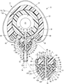
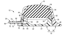
- FIG. 1 Front view of the subcutaneously implanted port shown in FIG. Top view of the subcutaneously implanted port shown in FIG. Bottom view of the subcutaneously implanted port shown in FIG. Right side view of the subcutaneous implantable port shown in FIG. VI-VI sectional view of FIG. VII-VII sectional view of FIG.
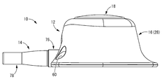
- FIGS. 1 to 7 show a subcutaneously implanted port 10 as the first embodiment of the present invention.
- the subcutaneously embedded port 10 has a structure in which a connection cap 14 is attached to a port body 12.
- the vertical direction means the vertical direction in FIG.
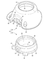
- the port body 12 has a structure in which the elastic lid 18 and the port member 20 are attached to the housing 16. Then, the opening of the recess 22 provided in the housing 16 is closed by the elastic lid 18, so that the cavity 24 for storing the drug solution whose wall is formed by the housing 16 and the elastic lid 18 is formed.
- the port member 20 communicates with the lumen 24.
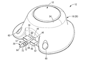
- the housing 16 is made of a hard synthetic resin or metal, and as shown in FIG. 11, it is a divided structure having a base housing member 26 and an outer housing member 28.
- the base housing member 26 has a substantially bottomed tubular shape including a peripheral wall portion 30 and a bottom wall portion 32, and a recess 22 that opens upward is formed in the central portion.
- the opening portion of the recess 22 is provided with an annular step portion 34 in which the inner peripheral corner portion of the peripheral wall portion 30 is enlarged in a notch shape.
- a port portion 36 is provided in a part of the peripheral wall portion 30 of the base housing member 26 in the circumferential direction.
- the port portion 36 has a substantially rectangular parallelepiped shape, is provided by partially thickening the peripheral wall portion 30 outward, and projects onto the outer peripheral surface of the peripheral wall portion 30.
- the peripheral wall portion 30 is formed with a communication hole 38 penetrating the port portion 36.
- a flange-shaped annular protrusion 40 projecting toward the outer peripheral side is formed at the lower end portion of the base housing member 26.
- a pair of fitting plate portions 42, 42 that project more toward the outer peripheral side are formed on both sides of the port portion 36 in the circumferential direction.
- the outer housing member 28 has a substantially cylindrical shape extending in the vertical direction.
- the upper portion of the outer housing member 28 has a tapered shape in which the inner and outer dimensions in the direction perpendicular to the axis gradually increase downward.
- the lower portion of the outer housing member 28 has a flare-shaped outer peripheral surface whose inner peripheral surface has a substantially constant inner dimension over substantially the entire circumference and whose outer peripheral dimension gradually increases downward. ing.
- the outer housing member 28 is a vertical wall portion 44 having a flat outer peripheral surface in which a part in the circumferential direction extends in the vertical direction.
- the vertical wall portion 44 is provided at a position corresponding to the port portion 36 of the base housing member 26 in the housing 16, and includes an opening window 46 that exposes the port portion 36 to the outer periphery.
- the outer housing member 28 includes a pair of locking protrusions 48, 48.
- the pair of locking protrusions 48, 48 have a substantially rectangular block shape.
- the pair of locking protrusions 48, 48 project from the vertical wall portion 44 in a direction substantially orthogonal to the vertical wall portion 44 on both sides in the width direction of the opening window 46.
- the pair of locking protrusions 48, 48 are arranged so as to be separated from each other in the width direction of the vertical wall portion 44, which is the circumferential direction of the outer housing member 28.
- the distance between the pair of locking protrusions 48, 48 facing each other is smaller than the opening width dimension of the opening window 46, and the pair of locking protrusions 48, 48 are the openings on the outer peripheral side of the opening window 46. It projects upward from both sides in the width direction and partially covers the opening window 46.
- the base end of each locking protrusion 48 connected to the vertical wall portion 44 by the pair of locking protrusions 48, 48 protruding above the opening window 46 has a widthwise dimension of the locking protrusion 48. It is made smaller than the other parts. As a result, the base end of the locking protrusion 48 is provided with a bending allowance portion 50 in which the cross-sectional area in the direction orthogonal to the protruding direction of the locking protrusion 48 is partially reduced.
- the pair of locking protrusions 48, 48 are each provided with engaging protrusions 52 protruding outward in the width direction at the protruding tip portions.
- the engaging protrusion 52 is a ridge extending in the vertical direction with a substantially semicircular cross section, and is continuously provided over the entire vertical direction of the locking protrusion 48.
- An annular pressing portion 54 projecting toward the inner circumference is provided in the opening portion at the upper end of the outer housing member 28.
- a locking claw 56 having a tapered cross-sectional shape and projecting downward is formed over the entire circumference.
- a fitting recess 58 corresponding to the fitting plate portions 42, 42 of the base housing member 26 is formed on the bottom surface of the outer housing member 28.
- a service hole 60 penetrating in the vertical direction is formed in a portion of the outer housing member 28 adjacent to the outer peripheral side of the fitting recess 58.
- the service hole 60 may be used for positioning during manufacturing or treatment, or may be provided with a fitting pin on the base housing member 26 or the port member 20 to fix the outer housing member 28 and the base housing member 26 or the port member 20. It can be used as appropriate.
- the outer housing member 28 is placed on the base housing member 26 from above and fixed to the peripheral wall portion 30 of the base housing member 26 in an extrapolated state. 16 is configured.
- the port portion 36 of the base housing member 26 is inserted into the opening window 46 of the outer housing member 28.
- the fitting plate portions 42, 42 of the base housing member 26 are inserted into the fitting recesses 58, 58 of the outer housing member 28.
- the base housing member 26 and the outer housing member 28 are positioned in the circumferential direction.
- the base housing member 26 and the outer housing member 28 are fixed to each other by, for example, ultrasonic welding, if necessary.
- the port portion 36 of the base housing member 26 to be inserted into the opening window 46 of the outer housing member 28 may be provided with a welding rib that protrudes from the upper surface or the like that is overlapped with the inner peripheral surface of the opening window 46.
- the position of forming the welding rib is not limited to the port portion 36, and the welding rib can be appropriately provided on the overlapping surface of the base housing member 26 and the outer housing member 28.
- the welding rib is provided as an outer. It can also be provided on the housing member 28 side.
- the port portion 36 of the base housing member 26 is inserted into the opening window 46 of the outer housing member 28, and the pair of fitting plate portions 42, 42 of the base housing member 26 are inserted into the pair of fitting recesses 58, 58 of the outer housing member 28. It can be fitted.
- the elastic lid 18 is attached to the housing 16.
- the elastic lid 18 is made of an elastic material such as an elastomer or rubber.
- the elastic lid 18 has a substantially disk shape with the vertical direction as the central axis direction as a whole.
- the elastic lid 18 is inserted into the inner circumference of the outer housing member 28, and the outer peripheral portion is sandwiched between the peripheral wall portion 30 of the base housing member 26 and the annular holding portion 54 of the outer housing member 28, which are vertically opposed to each other. Therefore, the outer peripheral portion is compressed in the vertical direction. As a result, the elastic lid 18 is attached to the housing 16 in a state where the outer peripheral portion is fluidly densely supported by the housing 16 over the entire circumference.
- a contrast ring 62 made of titanium, stainless steel, aluminum, an alloy thereof, or the like is externally fitted to the outer peripheral portion of the upper end of the peripheral wall portion 30 of the base housing member 26.
- the outer housing member 28 that covers the outer peripheral surface of the contrast ring 62 is made colorless and transparent or colored transparent that transmits visible light, and the display (marking) of the contrast ring 62 is visible from the outside.
- the contrast ring 62 is not essential, and for example, the housing 16 may be marked directly without the contrast ring 62.
- the elastic lid 18 and the inner cavity 24 for storing the chemical solution having the housing 16 as a wall portion are fluidly defined with respect to the external space.
- the inner cavity 24 is formed by fluid-tightly closing the opening of the recess 22 of the base housing member 26 with the elastic lid 18.
- the lumen 24 is open to the outside through a communication hole 38 provided in the port portion 36 of the base housing member 26.
- a port member 20 is attached to the communication hole 38 of the base housing member 26.
- the port member 20 has a substantially cylindrical tubular shape having a central hole 64.
- the port member 20 includes a base end cylinder portion 66 and a tip end cylinder portion 68, and the outer diameter dimension of the base end cylinder portion 66 is made larger than the outer diameter dimension of the tip end cylinder portion 68.
- the base end tubular portion 66 of the port member 20 is provided with a flange-shaped fitting protrusion 70 protruding from the outer peripheral surface.
- the outer peripheral surface of the tip tubular portion 68 of the port member 20 is provided with a plurality of barb-shaped convex portions 72 having a large diameter toward the base end side (upper side in FIGS. 6 and 9) arranged side by side in the length direction. There is.
- the port member 20 is attached to the base housing member 26 by inserting the base end cylinder portion 66 into the communication hole 38 of the base housing member 26.
- the central hole 64 of the port member 20 is communicated with the communication hole 38 of the base housing member 26 to the inner cavity 24 for storing the drug solution.
- the tip cylinder portion 68 of the port member 20 protrudes from the communication hole 38 of the base housing member 26, and the connection port of the present embodiment is configured by the tip cylinder portion 68 of the port member 20.
- the outer housing member 28 is assembled from above to the base housing member 26 in which the port member 20 is attached.
- the base housing member 26 and the outer housing member 28 are combined with each other in the vertical direction so that the tip tubular portion 68 of the port member 20 is inserted into the space between the pair of locking protrusions 48, 48.
- the base end tubular portion 66 (fitting protrusion 70) of the port member 20 is attached to the pair of locking protrusions 48, 48 of the outer housing member 28.
- the port member 20 is brought into contact with the base housing member 26 in the extraction direction and locked (see FIG. 9).
- the base end tubular portion 66 of the port member 20 is sandwiched between the base housing member 26 and the outer housing member 28, and the housing 16 of the port member 20 is sandwiched. It is prevented from falling out from.
- the structure for preventing the port member 20 from coming off from the housing 16 is configured by utilizing a pair of locking protrusions 48, 48 provided in the housing 16.
- the outer housing member 28 is provided with a region for accommodating the port portion 36 of the base housing member 26, the width dimension a of the base end (see FIG. 6) of the pair of locking protrusions 48, 48 is increased.
- Each deflection allowable portion 50 is formed so as to be smaller than the width dimension of the other portion.
- the bending allowance portion 50 of the present embodiment is provided by reducing the width dimension while maintaining the height dimension of the locking protrusion 48.
- the port portion 36 of the base housing member 26 is overlapped with the inner portions of the pair of locking protrusions 48, 48 in the width direction from the base end side, but the port portion 36 and the pair of locking protrusions are overlapped with each other.
- a gap is provided between 48 and 48, and the deformation of the bending allowance portion 50 is allowed by this gap.
- this gap may not be provided.
- an elastic body is interposed between the port portion 36 and the pair of locking protrusions 48, 48, and the deformation of the flexible body allows the deformation of the bending allowable portion 50. It is also possible to allow the deformation of the bending allowance portion 50 by a slight deformation of the port portion 36 and the pair of locking protrusions 48, 48.
- the pair of locking protrusions 48, 48 of the outer housing member 28 are arranged on both sides in the width direction with respect to the tip cylinder portion 68 of the port member 20 protruding from the base housing member 26. In other words, in a state where the base housing member 26 and the outer housing member 28 are combined, the tip cylinder portion 68 of the port member 20 is arranged between the pair of locking protrusions 48 and 48 facing each other.
- the tip tubular portion 68 of the port member 20 projects outward from the tips of the pair of locking protrusions 48, 48 through the opposite spaces of the pair of locking protrusions 48, 48 of the outer housing member 28.
- the portion of the tip cylinder portion 68 of the port member 20 where the convex portion 72 is provided is located outside the pair of locking protrusions 48, 48.
- a catheter 74 is attached to the port member 20.
- the catheter 74 is a soft tube, and the tip tube portion 68 of the port member 20 is inserted and connected to the connection side end portion of the catheter 74.
- the catheter 74 communicates with the cavity 24 for storing the drug solution of the subcutaneous implantable port 10 via the port member 20.
- the tip tubular portion 68 of the port member 20 is provided with a plurality of convex portions 72 on the outer peripheral surface, it is difficult for the catheter 74 fitted in the extrapolated state to come off.
- One end of the catheter 74 is attached to the port member 20 and connected to the subcutaneously implanted port 10, and the other end is connected to an internal lumen such as a blood vessel.
- connection cap 14 is attached to the connection portion between the port member 20 and the catheter 74.
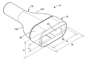
- the connection cap 14 has a sleeve shape (cylindrical shape) as a whole, and includes a base end side portion 76 and a tip end side portion 78 made of different materials.
- the base end side portion 76 is made of a material harder than the tip end side portion 78, and is formed of, for example, synthetic resin or metal.
- the base end side portion 76 integrally includes a bottomed tubular connecting portion 80 and a connecting portion 82 projecting from the connecting portion 80 to the tip end side (lower side in FIGS. 6 and 13).
- the base end side portion 76 may be entirely formed of a single material, or may be formed, for example, by combining a synthetic resin and a metal.
- the connecting portion 80 has a larger width dimension W in the circumferential direction of the housing 16 than the height dimension H in the height direction of the housing 16, and is of mutual length. It has a flat outer surface shape with two different orthogonal axes (major axis and minor axis).
- the connecting portion 80 of the present embodiment has an oval cross section as an outer surface.
- the base end side opening 83 of the connecting portion 80 has a substantially rectangular cross section, and the width dimension w is larger than the height dimension h.
- the pair of projecting portions 84, 84 are provided at positions facing each other in the width direction, and the width dimension of the inner peripheral surface of the connecting portion 80 is reduced in the portion where the pair of projecting portions 84, 84 are provided.
- the protruding tip surfaces of the pair of projecting portions 84, 84 expand toward the proximal end side at the proximal end side opening 83 of the connecting portion 80, in other words, from the proximal end side of the proximal end side opening 83 toward the back.
- the guide surface 86 is inclined inward in the width direction.
- Groove-shaped portions 88 extending in the vertical direction are provided behind the pair of protruding portions 84 and 84 on the peripheral wall of the connecting portion 80, respectively.
- the pair of locking portions 90, 90 of the present embodiment are formed by the stepped surfaces that are the inner surfaces of the pair of groove-shaped portions 88,88 and also the inner surfaces of the pair of protruding portions 84,84. There is. As described above, the pair of locking portions 90, 90 are provided on the proximal end side portion 76 of the connection cap 14.
- the connecting portion 82 has a substantially rectangular block shape, and a pair of anchor holes 92 and 92 penetrating in the vertical direction are formed on both side portions in the width direction (horizontal direction in FIG. 13). It is formed.
- a first insertion hole 94 having a circular cross section extending in the vertical direction and in the direction orthogonal to the width direction is formed in the central portion of the base end side portion 76 in the width direction.
- the first insertion hole 94 of the present embodiment has a tapered shape in which the end portion on the proximal end side extends in the left-right direction in FIG. 13 toward the proximal end side, but the end portion on the proximal end side of the first insertion hole 94
- the end portion may have substantially the same cross-sectional shape as the other portion.
- the tip end side portion 78 is made of a softer material than the base end side portion 76, and is formed of, for example, an elastic material such as a synthetic resin elastomer or rubber. As shown in FIGS. 12 to 14, the outer surface shape of the tip end side portion 78 smoothly changes from a flat oval shape to a circular shape from the base end to the tip end. On the proximal end side of the distal end side portion 78, a connecting recess 96 having a shape corresponding to the connecting portion 82 of the proximal end side portion 76 is formed.
- a pair of insertion portions 98, 98 corresponding to the pair of anchor holes 92, 92 of the connecting portion 82 extend in the vertical direction and are continuous with both upper and lower inner surfaces of the connecting recess 96.
- a second insertion hole 100 is formed in the central portion of the distal end side portion 78.
- the second insertion hole 100 is a circular hole corresponding to the first insertion hole 94, and is formed so as to penetrate from the base end to the tip end of the tip end side portion 78.
- the base end side portion 76 and the tip end side portion 78 are arranged in series and connected to each other.
- the connecting portion 82 of the proximal end side portion 76 is fixed in a state of being fitted into the connecting recess 96 of the distal end side portion 78.
- the insertion portions 98, 98 of the tip side portion 78 are provided in the inserted state with respect to the anchor holes 92, 92 of the base end side portion 76, so that the base end side portion 76 and the tip end side portion 78 are prevented from being separated.
- Anchors 102, 102 of the above are configured.
- the base end side portion 76 and the tip end side portion 78 may be fixed to each other by means such as welding after molding, but the base end side portion 76 and the tip end side portion 78 of the present embodiment are insert molded and two colors. It is molded in a state of being fixed to each other by molding or stepwise molding. As a result, the insertion portions 98, 98 of the distal end side portion 78 are formed in a state of being inserted into the anchor holes 92, 92 of the proximal end side portion 76.
- connection cap 14 is put on the tip cylinder portion 68 of the port member 20 protruding from the housing 16. Then, as shown in FIGS. 6 and 7, the connection cap 14 is put on the port member 20 to which the catheter 74 is attached in the exterior state, so that the catheter 74 is prevented from coming off from the port member 20. .. That is, the connection side end portion of the catheter 74 to the port member 20 is sandwiched between the outer peripheral surface of the port member 20 and the hard proximal end side portion 76 of the connection cap 14, so that the catheter 74 is connected by the port member 20. Can be firmly attached.
- the catheter 74 is sandwiched between the port member 20 and the connection cap 14 in the radial direction, for example, as follows. That is, the catheter 74 is first externally inserted so as to cover the port member 20 from the tip of the tip tubular portion 68 to a position extending to the convex portion 72 or a position beyond the convex portion 72.
- the catheter 74 is preferably inserted from the distal end surface of the locking protrusions 48, 48 of the housing 16 to the back side (base end side), and is inserted between the locking protrusions 48, 48.
- connection state between the catheter 74 and the port member 20 can be more reliably performed. It can be realized stably. Further, since the catheter 74 is sandwiched between the port member 20 and the locking protrusions 48, 48, the catheter 74 is less likely to come off from the port member 20 before the connection cap 14 is attached to the housing 16. .. Next, when the connection cap 14 is attached to the port member 20 on which the catheter 74 is attached, the catheter 74 sandwiched between the tip tube portion 68 and the port member 20 is attached to the tip tube portion 68 together with the connection cap 14.
- the outer diameter dimension of the catheter 74 mounted on the tip cylinder portion 68 of the port member 20 is made larger than the inner diameter dimension of the connection cap 14, so that the catheter 74 can be efficiently combined with the connection cap 14. Can be moved to the base end side.
- connection cap 14 is connected to a pair of locking protrusions 48, 48 of the outer housing member 28. That is, when the connection cap 14 is attached to the outer housing member 28, the tip tubular portion 68 of the port member 20 and the catheter 74 are inserted into the first insertion hole 94 and the second insertion hole 100 of the connection cap 14. It is brought close to the outer housing member 28. Then, the pair of locking protrusions 48, 48 of the outer housing member 28 are inserted between the pair of guide surfaces 86, 86 into the inner circumference of the base end side portion 76 of the connection cap 14.
- a pair of engaging protrusions 52, 52 provided on the pair of locking protrusions 48, 48 slide in contact with each other along the pair of guide surfaces 86, 86 of the connection cap 14, thereby forming a pair. It gets over the protrusions 84 and 84 and enters the pair of grooved portions 88 and 88. By providing the pair of guide surfaces 86, 86 in this way, the pair of engaging protrusions 52, 52 can easily penetrate into the pair of groove-shaped portions 88, 88.
- the pair of engaging protrusions 52, 52 By inserting the pair of engaging protrusions 52, 52 into the pair of groove-shaped portions 88, 88, the pair of engaging protrusions 52, 52 have a predetermined width x in axial projection with respect to the pair of protruding portions 84, 84.
- the pair of engaging projections 52, 52 are locked with respect to the pair of locking portions 90, 90 of the connection cap 14 in the extraction direction.
- the connection cap 14 is connected to the outer housing member 28 in a state of being prevented from coming off.
- the connection cap 14 is connected to the pair of locking protrusions 48, 48 of the outer housing member 28 by a snap fit.
- connection cap 14 is brought close to the outer housing member 28, and the pair of locking protrusions 48, 48 are fitted into the connection cap 14, so that the connection cap 14 is connected to the connection portion between the port member 20 and the catheter 74.
- the fixing of the connection cap 14 and the outer housing member 28 can be grasped by the response when the pair of engaging protrusions 52, 52 get over the pair of protrusions 84, 84 and enter the pair of groove-shaped portions 88, 88. Can be done.
- the base end side of the connection cap 14 has a flat shape, and particularly the hard base end side portion 76 has a flat shape, a pair of locking protrusions 48, 48 are attached to the connection cap 14. It is easy to apply force to the connection cap 14 when pushing it in.
- the base end side of the tip end side portion 78 has a flat outer surface shape
- the tip end side of the tip end side portion 78 has a circular outer surface
- the base end side is from the tip end side in the major axis direction. Is also said to have a large diameter.
- gentle stepped portions 104 are formed on both sides in the major axis direction on the outer peripheral surface of the intermediate portion of the tip end side portion 78.
- connection cap 14 When the user puts his / her finger on the stepped portions 104 and 104 to apply a force, the connection cap 14 can be easily pushed in the approaching direction to the outer housing member 28.
- the force applied to the stepped portion 104 is applied to the tip surface of the hard base end side portion 76 via the soft tip end side portion 78.
- the stepped portion 104 may be widened so as to intersect the axial direction of the connection cap 14, and may be configured by, for example, a plane substantially orthogonal to the axial direction of the connection cap 14.
- a pair of projecting portions 84, 84 are provided on both sides of the connection cap 14 in the long axis direction (width direction). Therefore, by applying a force in the pushing direction to both side portions in the width direction of the connection cap 14, a force is applied to the portion where the resistance force acts when the pair of engaging protrusions 52, 52 gets over the pair of protrusions 84, 84. Can act directly.
- the pair of locking portions 90, 90 of the connection cap 14 and the pair of locking protrusions 48, 48 of the outer housing member 28 may be in constant contact with each other and locked. Further, for example, as shown in FIG. 6, the pair of locking portions 90, 90 and the pair of locking protrusions 48, 48 are separated from each other, and the connection cap 14 is displaced in the direction of being removed from the outer housing member 28. By doing so, the pair of locking portions 90, 90 and the pair of locking protrusions 48, 48 can be brought into contact with each other and locked.
- the pair of locking protrusions 48, 48 are arranged apart from the tip cylinder portion 68 of the port member 20 on the outer side in the width direction. Therefore, when the pair of engaging protrusions 52, 52 get over the pair of protrusions 84, 84, the pair of locking protrusions 48, 48 are elastic in the direction of approaching the tip cylinder portion 68 of the port member 20. Flexible deformation is allowed.
- bending allowable portions 50 having a reduced cross-sectional area are provided, respectively, so that the pair of locking protrusions 48, 48 can be deformed by bending. It is advantageously allowed in each bending allowance 50.
- connection cap 14 By inserting the pair of locking protrusions 48, 48 into the connection cap 14 until the bottom inner surface of the connection portion 80 of the connection cap 14 abuts on the tip surfaces of the pair of locking protrusions 48, 48. , The connection cap 14 is attached at a predetermined position. As a result, the tip cylinder portion 68 of the port member 20 is housed in the connection cap 14, and the catheter 74 extrapolated to the tip cylinder portion 68 of the port member 20 is radially between the port member 20 and the connection cap 14. Is compressed to. As a result, the catheter 74 is prevented from coming off by attaching the connection cap 14.
- connection cap 14 Since the distal end side portion 78 of the connection cap 14 is soft, the inner peripheral surface of the distal end side portion 78 is expanded and deformed along the outer peripheral surface of the catheter 74 attached to the distal tubular portion 68.
- the inner peripheral surface of the connecting cap 14 preferably has a smooth shape without protrusions, thereby avoiding damage to the catheter 74 inserted into the connecting cap 14.
- connection cap 14 when a tensile force in the extraction direction acts on the catheter 74, a pair of engaging protrusions of a pair of locking portions 90 and 90 of the connection cap 14 and a pair of locking protrusions 48 and 48 of the outer housing member 28. 52 and 52 are locked. As a result, the connection cap 14 is prevented from coming off from the pair of locking protrusions 48, 48. Therefore, the connection cap 14 does not come off from the port member 20 together with the catheter 74, and the connection state between the catheter 74 and the port member 20 is stably maintained by the connection cap 14.
- the distal end side portion 78 of the connection cap 14 extending toward the distal end side of the distal end tubular portion 68 of the port member 20 and externally inserted into the catheter 74 has a pair of guide surfaces 86, 86 and a pair of locking portions 90, 90. It is made of a softer material than the base end side portion 76. Therefore, kinking of the catheter 74 is unlikely to occur at the tip of the connecting cap 14. Further, the soft tip side portion 78 has a cross-sectional shape changed from circular to oval, and the proximal end side has a flat shape to cover the distal end side of the hard proximal end side portion 76. Therefore, when the connection cap 14 is fitted to the pair of locking protrusions 48, 48, a force can be applied to the hard base end side portion 76 via the flexible tip side portion 78, and the connection cap 14 can be applied. It becomes easier to apply force to 14.
- connection cap 14 the hard base end side portion 76 and the soft tip end side portion 78 have a pair of insertion portions 98, 98 of the tip end side portion 78 inserted into a pair of anchor holes 92, 92 of the base end side portion 76. They are fixed to each other by a pair of anchor portions 102, 102.
- the proximal end side portion 76 and the distal end side portion 78 made of different materials are mechanically connected and cannot be separated, and the connection cap 14 is disassembled by the action of an external force such as a tensile force exerted from the catheter 74. Damage is avoided.
- the lap allowance x in the width direction between the pair of engaging protrusions 52, 52 of the pair of locking protrusions 48, 48 and the pair of locking portions 90, 90 is not particularly limited, but is preferably, for example. , 0.1 mm to 0.25 mm. According to this, while suppressing the force required for mounting the connection cap 14 on the pair of locking protrusions 48, 48, the connection cap 14 can be effectively pulled out from the pair of locking protrusions 48, 48. Can be prevented.
- connection cap may be entirely formed of a single material, or may be composed of three or more parts made of different materials.
- connection cap 14 of the above-described embodiment has a flat outer surface shape on the base end side, but the entire connection cap 14 may have a non-flat shape such as a cylindrical shape, or a flat shape such as an elliptical cylinder shape as a whole. It may be said that the tip side or the intermediate portion has a flat shape. Further, in the connection cap 14 having at least a flat outer surface shape, the major axis direction may be the height direction of the subcutaneously embedded port 10.
- connection cap 14 of the embodiment has a hole into which a pair of locking protrusions 48, 48 are inserted and a hole into which the tip tubular portion 68 of the port member 20 is inserted in the connection portion 80 of the base end side portion 76.
- it was connected and provided without partitioning.
- a hole into which a pair of locking protrusions 48, 48 are inserted and a port member The tip cylinder portion 68 of 20 and the hole into which the catheter 74 is inserted may be independent of each other.
- connection cap 14 can be removed from the outer housing member 28 by, for example, pulling strongly in the extraction direction.
- the connection cap 14 can also be irremovably fixed to the outer housing member 28.
- connection cap 14 and the housing 16 are replaced with a mounting structure in which the protrusions 84, 84 (locking portions 90, 90) of the connection cap 14 and the engagement protrusions 52, 52 of the housing 16 are locked as in the above embodiment.
- a threaded and threaded locking, or threaded structure it is possible to employ a threaded and threaded locking, or threaded structure.
- connection cap 14 and the housing 16 are preferably connected by locking with a protrusion as in the above embodiment. That is, when the connection cap 14 and the housing 16 are connected by a screw structure (screw), it is difficult to detect the fixed end by the tightening operation, so that the tightening variation or shortage is likely to occur, and the reliable connection state is stable. Hard to be expressed. On the other hand, with the uneven locking structure as in the embodiment, it is possible to stably obtain the desired fixed state. Further, since it is necessary to form a screw thread or a thread groove over the entire circumference of the fixed portion by the screw and the cross section becomes a relatively large circular shape, the height dimension is higher than the width dimension as in the embodiment, for example.
- connection cap protrudes from the housing in the vertical direction, which makes it easy to increase the size as a whole, and also makes it easy for a gap to occur due to a step between the two members, resulting in a fluid-tight catheter. There is a risk of hindering connection performance.
- a flat connection cap that is larger in the width direction (circumferential direction) than the height direction is adopted, and locking structures are provided on both sides in the width direction to reduce the size in the height direction. The distance from the center of the connecting member to the locking structure can be set large while suppressing the pressure. Therefore, in the connected state due to the locking structure, it is possible to suppress the rattling of the connection cap caused by the rattling of the uneven locking to the housing.
- the guide surface 86 is not necessarily limited to the one formed by substantially the entire tip surface of the protrusion 84, and for example, in the base end side opening 83 of the connection portion 80, C is formed at a corner portion on the base end side of the protrusion 84. It may be chamfered or provided with an R surface.
- the pair of locking protrusions 48, 48 may be provided on the base housing member 26.
- the housing 16 is not limited to the divided structure having the outer housing member 28 and the base housing member 26, and may be a single structure or may be composed of three or more divided bodies. good.
- the bending allowances provided in the pair of locking protrusions do not necessarily have to be located at the base ends of the pair of locking protrusions, and are provided, for example, in the intermediate portion of the pair of locking protrusions. obtain.
- the pair of engaging protrusions 52, 52 provided on the side surfaces of the pair of locking protrusions 48, 48 are provided with the pair of groove-shaped portions 88 provided behind the pair of guide surfaces 86, 86. , 88, and were locked to a pair of locking portions 90, 90.
- a locking hole is provided on the side surface of the pair of locking protrusions, and the pair of guide surfaces is inserted into the locking hole and locked in the extraction direction.
- a protrusion for locking may be provided.
- the catheter 74 attached to the tip cylinder portion 68 of the port member 20 in an extrapolated state has an end portion on the proximal end side inserted between a pair of locking protrusions 48, 48, and the end surface is the base of the port member 20. It may be in contact with the end cylinder portion 66. However, the distal end of the catheter 74 may be located in the middle of the pair of locking protrusions 48, 48 in the protruding direction, up to between the pair of locking protrusions 48, 48. May not be placed.
- the catheter 74 may be fixed to the port member 20 by means such as adhesion or welding.
- the catheter 74 can also be fixed to the port member 20 by pressing the catheter 74 against the outer peripheral surface of the port member 20 by the connecting cap 14.
Landscapes
- Health & Medical Sciences (AREA)
- Heart & Thoracic Surgery (AREA)
- Engineering & Computer Science (AREA)
- Animal Behavior & Ethology (AREA)
- Anesthesiology (AREA)
- Biomedical Technology (AREA)
- Hematology (AREA)
- Life Sciences & Earth Sciences (AREA)
- General Health & Medical Sciences (AREA)
- Public Health (AREA)
- Veterinary Medicine (AREA)
- Medical Informatics (AREA)
- Dermatology (AREA)
- Pulmonology (AREA)
- Media Introduction/Drainage Providing Device (AREA)
Priority Applications (2)
| Application Number | Priority Date | Filing Date | Title |
|---|---|---|---|
| JP2021533058A JP7591198B2 (ja) | 2019-07-12 | 2020-07-10 | 皮下埋込型ポート |
| JP2024160818A JP7839488B2 (ja) | 2019-07-12 | 2024-09-18 | 皮下埋込型ポート |
Applications Claiming Priority (2)
| Application Number | Priority Date | Filing Date | Title |
|---|---|---|---|
| JP2019129867 | 2019-07-12 | ||
| JP2019-129867 | 2019-07-12 |
Publications (1)
| Publication Number | Publication Date |
|---|---|
| WO2021010354A1 true WO2021010354A1 (ja) | 2021-01-21 |
Family
ID=74210875
Family Applications (1)
| Application Number | Title | Priority Date | Filing Date |
|---|---|---|---|
| PCT/JP2020/027154 Ceased WO2021010354A1 (ja) | 2019-07-12 | 2020-07-10 | 皮下埋込型ポート |
Country Status (2)
| Country | Link |
|---|---|
| JP (2) | JP7591198B2 (https=) |
| WO (1) | WO2021010354A1 (https=) |
Cited By (1)
| Publication number | Priority date | Publication date | Assignee | Title |
|---|---|---|---|---|
| CN118001505A (zh) * | 2024-04-08 | 2024-05-10 | 山东百多安医疗器械股份有限公司 | 一种防脱管、防翻转的输液港 |
Citations (6)
| Publication number | Priority date | Publication date | Assignee | Title |
|---|---|---|---|---|
| JPH0229269A (ja) * | 1988-05-26 | 1990-01-31 | Shiley Infusaid Inc | 挿入可能のアクセス装置 |
| JPH08215319A (ja) * | 1995-02-14 | 1996-08-27 | Nippon Sherwood Kk | 皮下埋込みポート |
| JPH1147278A (ja) * | 1997-07-30 | 1999-02-23 | Sumitomo Bakelite Co Ltd | 薬液注入ポート |
| JP2002500076A (ja) * | 1998-01-12 | 2002-01-08 | シー・アール・バード・インコーポレーテッド | 細長い隔膜を有する血管アクセスポート |
| JP2005169113A (ja) * | 2003-12-03 | 2005-06-30 | C R Bard Inc | カテーテル配置のためのポートステムマーキング |
| US20140309621A1 (en) * | 2013-04-10 | 2014-10-16 | Damon Caisello | Port Catheter Locking System and Method |
-
2020
- 2020-07-10 WO PCT/JP2020/027154 patent/WO2021010354A1/ja not_active Ceased
- 2020-07-10 JP JP2021533058A patent/JP7591198B2/ja active Active
-
2024
- 2024-09-18 JP JP2024160818A patent/JP7839488B2/ja active Active
Patent Citations (6)
| Publication number | Priority date | Publication date | Assignee | Title |
|---|---|---|---|---|
| JPH0229269A (ja) * | 1988-05-26 | 1990-01-31 | Shiley Infusaid Inc | 挿入可能のアクセス装置 |
| JPH08215319A (ja) * | 1995-02-14 | 1996-08-27 | Nippon Sherwood Kk | 皮下埋込みポート |
| JPH1147278A (ja) * | 1997-07-30 | 1999-02-23 | Sumitomo Bakelite Co Ltd | 薬液注入ポート |
| JP2002500076A (ja) * | 1998-01-12 | 2002-01-08 | シー・アール・バード・インコーポレーテッド | 細長い隔膜を有する血管アクセスポート |
| JP2005169113A (ja) * | 2003-12-03 | 2005-06-30 | C R Bard Inc | カテーテル配置のためのポートステムマーキング |
| US20140309621A1 (en) * | 2013-04-10 | 2014-10-16 | Damon Caisello | Port Catheter Locking System and Method |
Cited By (2)
| Publication number | Priority date | Publication date | Assignee | Title |
|---|---|---|---|---|
| CN118001505A (zh) * | 2024-04-08 | 2024-05-10 | 山东百多安医疗器械股份有限公司 | 一种防脱管、防翻转的输液港 |
| CN118001505B (zh) * | 2024-04-08 | 2024-06-04 | 山东百多安医疗器械股份有限公司 | 一种防脱管、防翻转的输液港 |
Also Published As
| Publication number | Publication date |
|---|---|
| JPWO2021010354A1 (https=) | 2021-01-21 |
| JP2024166352A (ja) | 2024-11-28 |
| JP7591198B2 (ja) | 2024-11-28 |
| JP7839488B2 (ja) | 2026-04-02 |
Similar Documents
| Publication | Publication Date | Title |
|---|---|---|
| EP2111887A2 (en) | Needleless luer access connector | |
| CN108697302B (zh) | 用于内窥镜的一次性空气/水阀和抽吸阀 | |
| JP7440491B2 (ja) | カテーテル組立体 | |
| US20100179478A1 (en) | Method of producing indwelling needle assembly and indwelling needle assembly | |
| US20060264911A1 (en) | Squeeze-actuated catheter connector and method | |
| JP2019527118A (ja) | 安全機能と圧力制御弁体を備えた静脈カテーテル装置 | |
| JP6617397B2 (ja) | 隔壁部材付きハブ組立体 | |
| KR20080056292A (ko) | 인-라인 밸브를 구비한 정맥내 카테터 및 그 관련 방법 | |
| JPWO2007132732A1 (ja) | 留置針組立体 | |
| WO2009123025A1 (ja) | 留置針組立体 | |
| KR102085062B1 (ko) | 혈관 접근 포트 및 이의 제조방법 | |
| JP2024166352A (ja) | 皮下埋込型ポート | |
| JP7134410B2 (ja) | 留置針および留置針組立体 | |
| JP6678379B2 (ja) | 隔壁付きハブ組立体 | |
| CN110368550B (zh) | 剪切型输液港结构及组装方法 | |
| JP2015066205A (ja) | 医療用コネクタ、混注管、三方活栓及び薬剤バック | |
| JP2019154953A (ja) | 針組立体 | |
| KR102194322B1 (ko) | 혈관 접근 포트 | |
| JPWO2015141366A1 (ja) | カテーテル組立体 | |
| CN205041966U (zh) | 药液注入口 | |
| WO2023074756A1 (ja) | 針組立体 | |
| JP2007236825A (ja) | 留置針組立体 | |
| JP7658364B2 (ja) | 針組立体 | |
| JP7227560B2 (ja) | 皮下埋込型ポートおよび皮下埋込型ポートの製造方法 | |
| WO2020189467A1 (ja) | カテーテル組立体 |
Legal Events
| Date | Code | Title | Description |
|---|---|---|---|
| 121 | Ep: the epo has been informed by wipo that ep was designated in this application |
Ref document number: 20840637 Country of ref document: EP Kind code of ref document: A1 |
|
| ENP | Entry into the national phase |
Ref document number: 2021533058 Country of ref document: JP Kind code of ref document: A |
|
| NENP | Non-entry into the national phase |
Ref country code: DE |
|
| 122 | Ep: pct application non-entry in european phase |
Ref document number: 20840637 Country of ref document: EP Kind code of ref document: A1 |