WO2021010274A1 - アンテナモジュール及びアンテナモジュール付車両ルーフ - Google Patents
アンテナモジュール及びアンテナモジュール付車両ルーフ Download PDFInfo
- Publication number
- WO2021010274A1 WO2021010274A1 PCT/JP2020/026832 JP2020026832W WO2021010274A1 WO 2021010274 A1 WO2021010274 A1 WO 2021010274A1 JP 2020026832 W JP2020026832 W JP 2020026832W WO 2021010274 A1 WO2021010274 A1 WO 2021010274A1
- Authority
- WO
- WIPO (PCT)
- Prior art keywords
- antenna
- substrate
- communication
- frequency band
- antenna module
- Prior art date
- Legal status (The legal status is an assumption and is not a legal conclusion. Google has not performed a legal analysis and makes no representation as to the accuracy of the status listed.)
- Ceased
Links
Images


Classifications
-
- H—ELECTRICITY
- H01—ELECTRIC ELEMENTS
- H01Q—ANTENNAS, i.e. RADIO AERIALS
- H01Q21/00—Antenna arrays or systems
-
- H—ELECTRICITY
- H01—ELECTRIC ELEMENTS
- H01Q—ANTENNAS, i.e. RADIO AERIALS
- H01Q1/00—Details of, or arrangements associated with, antennas
- H01Q1/27—Adaptation for use in or on movable bodies
- H01Q1/32—Adaptation for use in or on road or rail vehicles
- H01Q1/325—Adaptation for use in or on road or rail vehicles characterised by the location of the antenna on the vehicle
- H01Q1/3275—Adaptation for use in or on road or rail vehicles characterised by the location of the antenna on the vehicle mounted on a horizontal surface of the vehicle, e.g. on roof, hood, trunk
-
- H—ELECTRICITY
- H01—ELECTRIC ELEMENTS
- H01Q—ANTENNAS, i.e. RADIO AERIALS
- H01Q1/00—Details of, or arrangements associated with, antennas
- H01Q1/12—Supports; Mounting means
-
- H—ELECTRICITY
- H01—ELECTRIC ELEMENTS
- H01Q—ANTENNAS, i.e. RADIO AERIALS
- H01Q1/00—Details of, or arrangements associated with, antennas
- H01Q1/27—Adaptation for use in or on movable bodies
- H01Q1/32—Adaptation for use in or on road or rail vehicles
-
- H—ELECTRICITY
- H01—ELECTRIC ELEMENTS
- H01Q—ANTENNAS, i.e. RADIO AERIALS
- H01Q1/00—Details of, or arrangements associated with, antennas
- H01Q1/52—Means for reducing coupling between antennas; Means for reducing coupling between an antenna and another structure
- H01Q1/521—Means for reducing coupling between antennas; Means for reducing coupling between an antenna and another structure reducing the coupling between adjacent antennas
- H01Q1/523—Means for reducing coupling between antennas; Means for reducing coupling between an antenna and another structure reducing the coupling between adjacent antennas between antennas of an array
-
- H—ELECTRICITY
- H01—ELECTRIC ELEMENTS
- H01Q—ANTENNAS, i.e. RADIO AERIALS
- H01Q21/00—Antenna arrays or systems
- H01Q21/24—Combinations of antenna units polarised in different directions for transmitting or receiving circularly and elliptically polarised waves or waves linearly polarised in any direction
- H01Q21/245—Combinations of antenna units polarised in different directions for transmitting or receiving circularly and elliptically polarised waves or waves linearly polarised in any direction provided with means for varying the polarisation
-
- H—ELECTRICITY
- H01—ELECTRIC ELEMENTS
- H01Q—ANTENNAS, i.e. RADIO AERIALS
- H01Q21/00—Antenna arrays or systems
- H01Q21/30—Combinations of separate antenna units operating in different wavebands and connected to a common feeder system
Definitions
- This disclosure relates to an antenna module and a vehicle roof with an antenna module.
- Patent Document 1 discloses a roof module including a housing, an antenna, a metal panel, and a module substrate, all of which are integrated.
- radio wave obstacles may be provided around the roof module. It is desired to improve the radio wave propagation environment.
- the purpose of this disclosure is to improve the communication environment by radio waves in the antenna module.
- the antenna module of the present disclosure includes a substrate, at least one first communication antenna having a frequency band belonging to the first frequency range, and at least one first antenna having a frequency band belonging to a second frequency range higher than the first frequency range.
- the two communication antennas are provided, the at least one first communication antenna and the at least one second communication antenna are provided on the substrate, and the at least one first communication antenna is at least one. This is an antenna module provided at a position closer to the edge of the substrate than the two second communication antennas.
- the communication environment by radio waves in the antenna module is improved.
- FIG. 1 is a schematic perspective view showing a vehicle in which an antenna module is incorporated.
- FIG. 2 is a perspective view showing the antenna module.
- FIG. 3 is a plan view showing the antenna module.
- FIG. 4 is an explanatory diagram showing a radio wave propagation state in the antenna module.
- FIG. 5 is an explanatory diagram showing an example of arrangement of antennas on the substrate.
- FIG. 6 is a diagram showing an example of antenna arrangements 1 to 5 on the substrate.
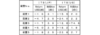
- FIG. 7 is a diagram showing simulation results of Return loss [dB] and gain Ave in Arrangements 1 to 5.
- the antenna module of this disclosure is as follows.
- the at least one first communication antenna and the at least one second communication antenna are provided on the substrate, and the at least one first communication antenna is the at least one second communication.
- At least one second communication antenna having a frequency band belonging to a second frequency range higher than the first frequency range is provided at a position farther from the edge of the substrate than the at least one first communication antenna. Therefore, even if there is a radio wave obstacle around the antenna module, the radio wave from the at least one second communication antenna is unlikely to be blocked by the obstacle.
- At least one first communication antenna having a frequency band belonging to the first frequency range is provided at a position closer to the edge of the substrate than the at least one second communication antenna. Even if there are radio wave obstacles around the antenna module, radio waves in a relatively low frequency band are easily diffracted and propagated. As a result, the communication environment by radio waves in the antenna module is improved.
- the first frequency range may be a frequency band of 2.1 GHz or less, and the second frequency range may be a frequency band of 5.7 GHz or more. As a result, the communication environment by radio waves in the antenna module is improved.
- An enclosure that becomes an obstacle to radio waves may be arranged around the substrate.
- the communication environment by radio waves in the antenna module is effectively improved.
- the first communication antenna having the lowest frequency band of the at least one first communication antenna is the substrate among the at least one first communication antenna and the at least one second communication antenna. It may be provided at the position closest to the edge of the antenna. Even if the first communication antenna in the lowest frequency band is provided at the position closest to the edge of the substrate, the radio wave from the first communication antenna in the lowest frequency band is easily diffracted and propagated.
- the second communication antenna having the highest frequency band of the at least one second communication antenna is the substrate among the at least one first communication antenna and the at least one second communication antenna. It may be provided at the position farthest from the edge of the antenna. Since the second communication antenna in the highest frequency band is provided at the position farthest from the edge of the substrate, the radio waves from the second communication antenna in the highest frequency band are shielded by obstacles. It is hard to be done.
- An antenna module according to any one of (1) to (5) and a vehicle roof that obstructs radio waves in at least a part of the frequency band are provided, and an opening is formed in the vehicle roof.
- a vehicle roof with an antenna module in which the antenna module is fitted in the opening may be used.
- the vehicle roof shields radio waves in at least a part of the frequency band inside and outside the vehicle. Since the antenna module is fitted into the opening of the vehicle roof, the antenna can communicate well with the outside. At this time, the roof may interfere with communication.
- at least one second communication antenna having a frequency band belonging to a second frequency range higher than the first frequency range is provided at a position farther from the edge of the substrate than the at least one first communication antenna. There is.
- the radio waves from the at least one second communication antenna are unlikely to be shielded by the vehicle roof.
- at least one first communication antenna having a frequency band belonging to the first frequency range is provided at a position closer to the edge of the substrate than the at least one second communication antenna. Even if there is a vehicle roof around the antenna module, radio waves in a relatively low frequency band are easily diffracted and propagated. As a result, the communication environment by radio waves in the antenna module is improved.
- FIG. 1 is a schematic perspective view showing a vehicle 10 in which the antenna module 20 is incorporated.
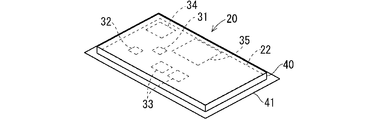
- FIG. 2 is a perspective view showing the antenna module 20.
- FIG. 3 is a plan view showing the antenna module 20.
- the vehicle 10 to which the antenna module 20 is assembled includes a body 12.
- the body 12 is a portion forming the outer shape of the vehicle 10.
- the body 12 may be a monocoque body or a body mounted on a rudder frame.
- the body 12 includes a vehicle roof portion 13.
- the vehicle roof portion 13 is a portion provided above the vehicle interior.
- the vehicle roof portion 13 may be integrally formed with other portions of the body 12.
- the vehicle roof portion 13 may be separated from the other portion of the body 12 and may be mounted on the other portion of the body 12.
- the vehicle roof portion 13 may be formed of metal or resin.
- the vehicle roof portion 13 is formed of a metal plate.
- the vehicle roof portion 13 shields radio waves.
- the vehicle roof portion 13 may be made of resin.
- the vehicle roof portion 13 may be provided with a radio wave shielding layer.
- the radio wave shielding layer may be a portion made of a metal such as aluminum or iron.
- the radio wave shielding layer may be a layer having selective radio wave shielding property, such as a well-known frequency selection film (FSS: Frequency Selective Surface).
- FSS Frequency Selective Surface
- the case where the vehicle roof portion 13 is made of metal or the case where the vehicle roof portion 13 is provided with a radio wave shielding layer is an example of a vehicle roof that hinders radio waves in at least a part of the frequency band.
- An opening 13a is formed in the vehicle roof portion 13.
- the opening 13a is formed in the rear side of the vehicle roof portion 13.
- the opening 13a is located at the center in the vehicle width direction.
- the front-rear direction is a front-rear direction with respect to the vehicle 10
- the traveling direction of the vehicle 10 is the front side
- the backward direction is the rear side.
- the left-right direction is based on the state of facing the front side with respect to the vehicle 10.
- the left-right direction is also the width direction.
- the vertical direction is a vertical direction with respect to the vehicle 10.
- the opening may be located closer to the front side of the vehicle 10 or may be biased to either one side.
- the antenna module 20 is fitted into the opening 13a.
- a vehicle roof 70 with an antenna module in which the antenna module 20 is fitted in the opening 13a of the vehicle roof portion 13 can be grasped.
- the antenna module 20 includes a substrate 22 and a plurality of types of antennas 31, 32, 33, 34, 35.
- the substrate 22 includes an insulating plate.
- the substrate 22 may be a metal plate that does not include an insulating plate.
- the substrate 22 may be a composite plate of an insulating member and a metal member.
- a plurality of types of antennas 31, 32, 33, 34, and 35 are provided on the front side (outside of the vehicle) of the substrate 22.
- a conductor layer serving as a ground is formed on the back side (vehicle interior side) surface of the insulating plate by a metal foil or the like.
- antennas 31, 32, 33, 34, 35 are communication antennas with different frequency bands.
- the communication here includes two-way communication and one-way communication.
- the antennas 31, 32, 33, 34, 35 may be planar antennas or antennas having a three-dimensional structure.
- the communication antenna 31 communicates with the highest frequency band among the plurality of types of antennas 31, 32, 33, 34, and 35.
- the communication antenna 31 is provided at a position that is the farthest distance D1 from the edge of the substrate 22 among the plurality of types of antennas 31, 32, 33, 34, and 35.
- the communication antenna 35 communicates with the lowest frequency band among the plurality of types of antennas 31, 32, 33, 34, and 35.
- the communication antenna 35 is provided at a position at a distance D5 closest to the edge of the substrate 22 among the plurality of types of antennas 31, 32, 33, 34, and 35.
- the distance between the antennas 31, 32, 33, 34, 35 and the edge of the substrate 22 is the shortest distance between the outer edge of the antennas 31, 32, 33, 34, 35 and the outer edge of the substrate 22.
- antennas 31, 32, 33, 34, and 35 for antennas that communicate with wireless base stations on public communication lines or dedicated communication lines, for vehicle-to-vehicle communication or road-to-vehicle communication. It is assumed that the antenna is an antenna for receiving GPS signals, and the like.
- the antenna 31 is a communication antenna in the 28 GHz band.
- the antenna 31 is provided at a position closer to one short side from the center of the substrate 22.
- the distance between the antenna 31 and the edge of the substrate 22 is D1.
- the antenna 32 is a communication antenna in the 5.8 GHz band.
- the antenna 32 is provided at a position close to one corner of the substrate 22.
- the distance between the antenna 32 and the edge of the substrate 22 is D2.
- the antenna 33 is a communication antenna in the 5 GHz band.
- the antenna 33 is provided at an intermediate portion in the long side direction of the substrate 22 and at a position close to one long side. Since the antenna 33 is a diversity antenna, a plurality of antennas (two here) are shown.
- the distance between the antenna 33 and the edge of the substrate 22 is D3.
- the antenna 34 is a communication antenna in the 1.5 GHz band.
- the antenna 34 is provided at a position close to the other corner of the substrate 22.
- the distance between the antenna 34 and the edge of the substrate 22 is D4.
- the antenna 35 is a communication antenna in the 760 MHz band.
- the antenna 35 is provided at a position in the middle portion in the long side direction of the substrate 22 and close to the other long side.
- the distance between the antenna 35 and the edge of the substrate 22 is D5.
- the antenna 31 is a communication antenna for communicating in the highest frequency band (28 GHz).
- the distance D1 between the antenna 31 and the edge of the substrate 22 is larger than the other distances D2, D3, D4, and D5. That is, the antenna 31 for the highest frequency band is located farther from the edge of the substrate 22 than the other antennas 32, 33, 34, 35.
- the antenna 35 is a communication antenna for communicating in the lowest frequency band (760 MHz band).
- the distance D5 between the antenna 35 and the edge of the substrate 22 is smaller than the other distances D1, D2, D3, and D4. That is, the antenna 35 for the lowest frequency band is located closer to the edge of the substrate 22 than the other antennas 31, 32, 33, 34.
- the distances D2, D3, and D4 between the antennas 32, 33, 34 for the frequency band between the highest frequency band and the lowest frequency band and the edge of the substrate 22 are smaller than the distance D1 and larger than the distance D5. large. That is, the antennas 32, 33, and 34 for the intermediate frequency band are located closer to the edge of the substrate 22 than the antenna 31, and are located farther from the edge of the substrate 22 than the antenna 35.
- the distance between the antennas 32, 33, and 34 for the intermediate frequency band and the edges of the substrate 22 is not particularly limited.
- the distance between the antennas 32, 33, 34 and the edge of the substrate 22 may increase.
- the frequency band of the antenna 32 (5.8 GHz band) is higher than the frequency band of the antenna 33 (5 GHz band).
- the frequency band (5 GHz band) of the antenna 33 is higher than the frequency band (1.5 GHz band) of the antenna 34.
- the distance D2 between the antenna 32 and the edge of the substrate 22 may be larger than the distance D3 between the antenna 33 and the edge of the substrate 22.
- the distance D3 between the antenna 33 and the edge of the substrate 22 may be larger than the distance D4 between the antenna 34 and the edge of the substrate 22.
- the substrate 22 and the antennas 31, 32, 33, 34, 35 are housed in the case 40.
- the case 40 is made of resin or the like.
- the case 40 is formed in a flat rectangular parallelepiped shape.
- the substrate 22 is housed in the case 40 with the four sides of the peripheral edge of the substrate 22 facing the four sides of the peripheral wall of the case 40.
- the collar portion 41 projects from the lower portion of the case 40 toward the outer periphery.
- the flange portion 41 can come into contact with the edge of the opening 13a from the vehicle interior side.
- the antenna module 20 is positioned with respect to the vehicle roof portion 13.
- the outward surface of the antenna module 20 may be flush with the outward surface of the vehicle roof portion 13, or may project from the outward surface of the vehicle roof portion 13.
- FIG. 4 is an explanatory diagram schematically showing the propagation state of radio waves in the antenna module 20.
- the antennas 31 and 35 are drawn as graphic symbols.
- the positions of the antennas 31 and 35 on the substrate 22 reflect the distances D1 and D5.
- an enclosure 50 that acts as an obstacle to radio waves is arranged around the antenna module 20.
- the enclosure 50 is the vehicle roof portion 13 when the vehicle roof portion 13 is made of metal, or the radio wave shielding layer portion when the vehicle roof portion 13 is provided with the radio wave shielding layer. Is assumed. Further, when a metal frame is provided around the antenna module 20, it can be assumed that the metal frame becomes an enclosure 50 that becomes an obstacle of radio waves.
- the enclosure 50 can shield radio waves radiated from the antennas 31, 35 or to the antennas 31, 35.
- the radio waves radiated from the antennas 31 and 35 are radiated upward and diagonally upward to some extent, but are close to the horizontal direction. It is difficult to radiate directly to the angle.
- the antenna 35 that communicates in the lowest frequency band among the plurality of types of antennas 31, 32, 33, 34, and 35 is provided at a position that is the closest distance D5 from the edge of the substrate 22. Since the enclosure 50 is located on the outer periphery of the substrate 22, the antenna 35 is located relatively close to the enclosure 50.
- the radio wave W1 in the low frequency band is relatively easy to diffract. Therefore, even if the antenna 35 is provided near the enclosure 50, the radio wave W1 radiated from the antenna 35 can be diffracted and propagated.
- the antenna 31 that communicates by the highest frequency band among the plurality of types of antennas 31, 32, 33, 34, and 35 is provided at a position that is the farthest distance D1 from the edge of the substrate 22. Since the enclosure 50 is located on the outer periphery of the substrate 22, the antenna 35 is located relatively far from the enclosure 50.
- the radio wave W2 in the high frequency band has high straightness. However, since the antenna 35 is relatively far from the enclosure 50, the radio wave W2 in the high frequency band is also radiated at an angle relatively close to horizontal.
- the communication antenna 31 having the highest frequency band among the plurality of types of antennas 31, 32, 33, 34, and 35 is the edge of the substrate 22. It is installed at the position farthest from. Therefore, even if there is a radio wave obstacle (for example, the enclosure 50) around the antenna module 20, the radio wave W2 in the highest frequency band is difficult to be shielded by the obstacle and is as close to horizontal as possible. Can be radiated around at an angle. As a result, good communication is possible via the communication antenna 31 in the highest frequency band.
- a radio wave obstacle for example, the enclosure 50
- the communication antenna 35 having the lowest frequency band among the plurality of types of antennas 31, 32, 33, 34, and 35 is provided at a position closest to the edge of the substrate 22. Even if there is a radio wave obstacle (for example, an enclosure 50) around the antenna module 20, the radio wave W1 in the lowest frequency band is easily diffracted and propagated. As a result, good communication is possible even through the communication antenna 35 in the lowest frequency band. As a result, the communication environment by radio waves in the antenna module 20 is improved.
- a radio wave obstacle for example, an enclosure 50
- the enclosure 50 that becomes an obstacle to radio waves is arranged around the substrate 22, the communication environment by radio waves in the antenna module 20 is effectively improved.
- the vehicle roof portion 13 can shield radio waves in at least a part of the frequency band inside and outside the vehicle.
- the antennas 31, 32, 33, 34, and 35 can communicate well with the outside.
- the vehicle roof portion 13 may interfere with radio waves.
- the communication antenna 31 with the highest frequency band is provided farthest from the edge of the substrate 22, and the communication antenna 35 with the lowest frequency band is provided closest to the edge of the substrate 22. Therefore, the communication environment by radio waves in the antenna module 20 is improved.
- the communication antenna 31 having the highest frequency band is provided at the position farthest from the edge of the substrate 22, and the communication antenna 35 having the lowest frequency band is provided at the position closest to the edge of the substrate 22.
- the antenna module 20 includes a substrate 22, at least one first communication antenna having a frequency band belonging to the first frequency range, and at least one antenna having a frequency band belonging to a second frequency range higher than the first frequency range.
- a second communication antenna is provided, the at least one first communication antenna and the at least one second communication antenna are provided on the substrate 22, and the at least one first communication antenna is the same. It may be understood that the antenna is provided at a position closer to the edge of the substrate 22 than at least one second communication antenna.
- the first frequency range may be a frequency band of 2.1 GHz or less
- the second frequency range may be a frequency band of 5.7 GHz or more
- the first frequency band may be 200 MHz or more and 2.1 GHz or less
- the second frequency range may be 5.7 GHz or more and 40 GHz or less.
- the antenna 31 is a communication antenna in the 28 GHz band
- the antenna 32 is a communication antenna in the 5.8 GHz band
- the antenna 33 is a communication antenna in the 5 GHz band
- the antenna 34 is a 1.5 GHz band. It is assumed that the antenna is a band-based communication antenna, and the antenna 35 is a band-based communication antenna.
- at least one first communication antenna is the antenna 34 and the antenna 35.
- at least one second communication antenna is an antenna 31 and an antenna 32.
- the antenna 33 is an antenna that does not correspond to either the first communication antenna or the second communication antenna.
- At least one first communication antenna, antennas 34, 35 are D4, D5), and at least one second communication antenna, antennas 31, 32 (distances from the edge are D1, D2). It is provided closer to the edge of the substrate 22 (that is, D4 and D5 are smaller than D1 and D2).
- At least one second communication antenna 31, 32 having a frequency band belonging to a second frequency range higher than the first frequency range is more than the at least one first communication antenna 34, 35. It is provided at a position away from the edge of the substrate 22. Therefore, even if there is an obstacle of radio waves around the antenna module 20, the radio waves from at least one of the second communication antennas 31 and 32 are unlikely to be blocked by the obstacle. Further, at least one first communication antenna 33, 34 according to a frequency band belonging to the first frequency range is provided at a position closer to the edge of the substrate than the at least one second communication antenna 31, 32. Even if there are radio wave obstacles around the antenna module 20, radio waves in a relatively low frequency band are easily diffracted and propagated. As a result, the communication environment by radio waves in the antenna module 20 is improved.
- the antenna for wireless automobile locking / unlocking system is for 315 / 433MHz
- the antenna for ITS (Intelligent Transport Systems) in Japan is for 755MHz to 765MHz
- mobile communication for example, LTE (Long Term Evolution))
- remote start antenna for 920MHz
- GNSS Global Navigation Satellite System, GPS
- antenna for 1.57542GHz satellite radio
- antenna for Bluetooth (trademark) or Wi-Fi (trademark) is 2.4 / 5 GHz
- antenna for mobile communication for example, 5G Sub6) is 3.6 to 4 .1GHz / 4.5-4.6GHz (in Japan)
- American ITS (Intelligent Transport Systems) antenna for 5.9GHz
- mobile communication for example, 5G Sub6
- the simulation conditions are as follows. It is assumed that the radio wave obstacle 124 corresponding to the roof is arranged around the substrate 122.
- the board 122 has two antennas 131 (760 MHz) for Japanese ITS, two antenna 132 (800 MHz band for TEL) for mobile communication, an antenna 133 (5.9 GHz) for American ITS, and (5G) for mobile communication. It was decided to arrange two antennas 134 (3.6 to 4.1 GHz / 4.5 to 4.6 GHz (in Japan)) of Sub6). It was taken into consideration that the GPS amplifier board 140 is also arranged on the board 122.
- arrangement 1, arrangement 2, arrangement 3, arrangement 4, and arrangement 5 in which the arrangement positions of the antennas 131, 132, 133, and 134 were changed were examined.
- the arrangement positions of the antennas 131, 132, 133, and 134 in the respective arrangements 1 to 5 are shown in FIG.
- FIG. 6 the positions of the centers of the antennas 131, 132, 133, and 134 are shown in XY coordinates with the center of the substrate 22 as the origin.
- the antennas 131 and 132 are the first antennas.
- the antenna 133 is the second antenna, and the antenna 134 is neither the first antenna nor the second antenna.
- the antennas 131 and 132, which are the first antennas are closer to the edge than the antenna 133, which is the second antenna.
- the first antenna may be provided at a position where the center of the substrate and the center of the antenna are 20 cm to 90 cm, preferably about 20 cm.
- the second antenna may be provided at a position where the center of the substrate and the center of the antenna are 75 cm to 90 cm, preferably about 70 cm.
- a board and a plurality of types of antennas provided on the board are provided, and the plurality of types of antennas are communication antennas having different frequency bands from each other, and the highest frequency band among the plurality of types of antennas.
- the communication antenna according to is provided at a position farthest from the edge of the substrate among the plurality of types of antennas, and the communication antenna with the lowest frequency band among the plurality of types of antennas is the plurality of types. It is an antenna module provided at a position closest to the edge of the substrate in the antenna.
- the communication antenna having the highest frequency band among the plurality of types of antennas is provided at the position farthest from the edge of the substrate.
- the radio wave in the highest frequency band is unlikely to be blocked by the obstacle.
- the communication antenna having the lowest frequency band among the plurality of types of antennas is provided at the position closest to the edge of the substrate. Even if there are radio wave obstacles around the antenna module, the radio waves in the lowest frequency band are easily diffracted and propagated. As a result, the communication environment by radio waves in the antenna module is improved.
- An enclosure that becomes an obstacle to radio waves may be arranged around the substrate.
- the communication environment by radio waves in the antenna module is effectively improved.
- this disclosure includes the following vehicle roof with antenna module.
- the antenna module and a vehicle roof that obstructs radio waves in at least a part of the frequency bands are provided, an opening is formed in the vehicle roof, and the antenna module is fitted in the opening. It may be a vehicle roof with an antenna module.
- the vehicle roof shields radio waves in at least a part of the frequency band inside and outside the vehicle. Since the antenna module is fitted into the opening of the vehicle roof, the antenna can communicate well with the outside. At this time, the roof may interfere with communication. However, the communication antenna having the highest frequency band among the plurality of types of antennas is provided at the position farthest from the edge of the substrate. Therefore, the radio waves in the highest frequency band are unlikely to interfere with the vehicle roof.
- the communication antenna having the lowest frequency band among the plurality of types of antennas is provided at the position closest to the edge of the substrate.
- the radio waves in the lowest frequency band easily diffract and propagate through the vehicle roof. Therefore, the communication environment by radio waves in the antenna module is improved.
- Vehicle 12 Body 13 Vehicle roof part 13a Opening 20 Antenna module 22 Board 31, 32, 33, 34, 35 Antenna 40 Case 41 Collar 50 Enclosure 70 Vehicle roof with antenna module
Landscapes
- Engineering & Computer Science (AREA)
- Remote Sensing (AREA)
- Details Of Aerials (AREA)
- Support Of Aerials (AREA)
- Variable-Direction Aerials And Aerial Arrays (AREA)
Priority Applications (3)
| Application Number | Priority Date | Filing Date | Title |
|---|---|---|---|
| US17/625,373 US12009582B2 (en) | 2019-07-12 | 2020-07-09 | Antenna module and vehicle roof with antenna module |
| JP2021533013A JP7231034B2 (ja) | 2019-07-12 | 2020-07-09 | アンテナモジュール及びアンテナモジュール付車両ルーフ |
| CN202080047872.7A CN114072969A (zh) | 2019-07-12 | 2020-07-09 | 天线模块及带天线模块的车辆车顶 |
Applications Claiming Priority (2)
| Application Number | Priority Date | Filing Date | Title |
|---|---|---|---|
| JP2019-129835 | 2019-07-12 | ||
| JP2019129835 | 2019-07-12 |
Publications (1)
| Publication Number | Publication Date |
|---|---|
| WO2021010274A1 true WO2021010274A1 (ja) | 2021-01-21 |
Family
ID=74210763
Family Applications (1)
| Application Number | Title | Priority Date | Filing Date |
|---|---|---|---|
| PCT/JP2020/026832 Ceased WO2021010274A1 (ja) | 2019-07-12 | 2020-07-09 | アンテナモジュール及びアンテナモジュール付車両ルーフ |
Country Status (4)
| Country | Link |
|---|---|
| US (1) | US12009582B2 (https=) |
| JP (1) | JP7231034B2 (https=) |
| CN (1) | CN114072969A (https=) |
| WO (1) | WO2021010274A1 (https=) |
Families Citing this family (3)
| Publication number | Priority date | Publication date | Assignee | Title |
|---|---|---|---|---|
| US11008731B2 (en) * | 2017-03-31 | 2021-05-18 | Komatsu Ltd. | Work vehicle |
| JP7501122B2 (ja) * | 2020-06-04 | 2024-06-18 | 株式会社オートネットワーク技術研究所 | 車載アンテナモジュール |
| US20260045682A1 (en) * | 2024-08-08 | 2026-02-12 | Ford Global Technologies, Llc | Vehicle antenna assembly with exposed ground plane |
Citations (4)
| Publication number | Priority date | Publication date | Assignee | Title |
|---|---|---|---|---|
| JP2003017916A (ja) * | 2001-07-04 | 2003-01-17 | Nippon Antenna Co Ltd | 車載用アンテナ |
| JP2016197061A (ja) * | 2015-04-03 | 2016-11-24 | 株式会社日本自動車部品総合研究所 | 車両用アンテナユニット、方向推定システム |
| JP2017060038A (ja) * | 2015-09-17 | 2017-03-23 | パナソニックIpマネジメント株式会社 | アンテナおよびそれを利用した車両 |
| JP2019078041A (ja) * | 2017-10-23 | 2019-05-23 | トヨタ自動車株式会社 | キーユニット |
Family Cites Families (13)
| Publication number | Priority date | Publication date | Assignee | Title |
|---|---|---|---|---|
| US6646614B2 (en) * | 2001-11-07 | 2003-11-11 | Harris Corporation | Multi-frequency band antenna and related methods |
| JP3420233B2 (ja) * | 2001-11-28 | 2003-06-23 | 日本アンテナ株式会社 | 複合アンテナ |
| JP2003332817A (ja) | 2002-05-14 | 2003-11-21 | Alps Electric Co Ltd | アンテナシステム |
| US6989785B2 (en) | 2003-10-06 | 2006-01-24 | General Motors Corporation | Low-profile, multi-band antenna module |
| US7034753B1 (en) * | 2004-07-01 | 2006-04-25 | Rockwell Collins, Inc. | Multi-band wide-angle scan phased array antenna with novel grating lobe suppression |
| US7423597B2 (en) * | 2006-02-09 | 2008-09-09 | Marvell World Trade Ltd. | Dual band WLAN antenna |
| JP2008278447A (ja) * | 2006-09-12 | 2008-11-13 | Asahi Glass Co Ltd | 自動車用高周波ガラスアンテナ及び自動車用の窓ガラス板 |
| US7663563B2 (en) | 2007-04-04 | 2010-02-16 | Asahi Glass Company, Limited | High frequency wave glass antenna for an automobile and window glass sheet for an automobile with the same |
| JP2011091557A (ja) * | 2009-10-21 | 2011-05-06 | Panasonic Corp | アンテナ装置 |
| JP5924959B2 (ja) * | 2012-01-31 | 2016-05-25 | 日本放送協会 | アンテナ装置 |
| TWI593166B (zh) * | 2015-10-27 | 2017-07-21 | 合勤科技股份有限公司 | 無線網路裝置 |
| JP6393706B2 (ja) | 2016-04-28 | 2018-09-19 | 矢崎総業株式会社 | ルーフモジュール |
| KR102217182B1 (ko) * | 2018-11-19 | 2021-02-18 | 삼성전자주식회사 | 차량용 통신 장치 |
-
2020
- 2020-07-09 JP JP2021533013A patent/JP7231034B2/ja active Active
- 2020-07-09 US US17/625,373 patent/US12009582B2/en active Active
- 2020-07-09 CN CN202080047872.7A patent/CN114072969A/zh active Pending
- 2020-07-09 WO PCT/JP2020/026832 patent/WO2021010274A1/ja not_active Ceased
Patent Citations (4)
| Publication number | Priority date | Publication date | Assignee | Title |
|---|---|---|---|---|
| JP2003017916A (ja) * | 2001-07-04 | 2003-01-17 | Nippon Antenna Co Ltd | 車載用アンテナ |
| JP2016197061A (ja) * | 2015-04-03 | 2016-11-24 | 株式会社日本自動車部品総合研究所 | 車両用アンテナユニット、方向推定システム |
| JP2017060038A (ja) * | 2015-09-17 | 2017-03-23 | パナソニックIpマネジメント株式会社 | アンテナおよびそれを利用した車両 |
| JP2019078041A (ja) * | 2017-10-23 | 2019-05-23 | トヨタ自動車株式会社 | キーユニット |
Also Published As
| Publication number | Publication date |
|---|---|
| JP7231034B2 (ja) | 2023-03-01 |
| US20220271421A1 (en) | 2022-08-25 |
| US12009582B2 (en) | 2024-06-11 |
| CN114072969A (zh) | 2022-02-18 |
| JPWO2021010274A1 (https=) | 2021-01-21 |
Similar Documents
| Publication | Publication Date | Title |
|---|---|---|
| TW554572B (en) | Low-profile, multi-antenna module, and method of integration into a vehicle | |
| JP5487938B2 (ja) | 車両用複合アンテナ装置 | |
| KR102707822B1 (ko) | 차량에 배치되는 안테나 모듈 | |
| JP7231034B2 (ja) | アンテナモジュール及びアンテナモジュール付車両ルーフ | |
| EP3588673B1 (en) | Under-roof antenna modules for vehicles | |
| KR20210091176A (ko) | 차량에 탑재되는 안테나 시스템 | |
| CN114128043B (zh) | 天线模块 | |
| JP2009124577A (ja) | 複合アンテナ | |
| EP3913742B1 (en) | Antenna module for a vehicle with radiant elements arrangement | |
| US20200185820A1 (en) | Integrated vehicle antenna | |
| CN116231274A (zh) | 具有倾斜天线阵列的电子设备 | |
| JP2017168938A (ja) | 車載用アンテナ装置 | |
| CN109301502B (zh) | 以太网智能型天线 | |
| JP7501122B2 (ja) | 車載アンテナモジュール | |
| US10897085B2 (en) | Antenna and antenna system | |
| US20240317330A1 (en) | Vehicle spoiler assembly | |
| KR102215659B1 (ko) | 안테나 어셈블리 및 주파수 적응성 그라운드 레이어 | |
| CN220963760U (zh) | 车载鲨鱼鳍集成天线 | |
| CN218632452U (zh) | Gnss与5g的混合天线 | |
| KR102461260B1 (ko) | 안테나 장치 | |
| US20240322448A1 (en) | Thin sheet-like antenna for narrowband vehicular communication | |
| JP2007153019A (ja) | ドア内蔵車載アンテナ | |
| US20240250437A1 (en) | Thin sheet-like antenna for narrowband vehicular communication | |
| EP4568018A1 (en) | Antenna assembly, signal transmission apparatus, and vehicle | |
| JP2024143925A (ja) | アンテナ装置 |
Legal Events
| Date | Code | Title | Description |
|---|---|---|---|
| 121 | Ep: the epo has been informed by wipo that ep was designated in this application |
Ref document number: 20841525 Country of ref document: EP Kind code of ref document: A1 |
|
| ENP | Entry into the national phase |
Ref document number: 2021533013 Country of ref document: JP Kind code of ref document: A |
|
| NENP | Non-entry into the national phase |
Ref country code: DE |
|
| 122 | Ep: pct application non-entry in european phase |
Ref document number: 20841525 Country of ref document: EP Kind code of ref document: A1 |