WO2021004642A1 - A camera calibration method, a computer program, a computer-readable recording medium and a camera calibration system - Google Patents
A camera calibration method, a computer program, a computer-readable recording medium and a camera calibration system Download PDFInfo
- Publication number
- WO2021004642A1 WO2021004642A1 PCT/EP2019/068763 EP2019068763W WO2021004642A1 WO 2021004642 A1 WO2021004642 A1 WO 2021004642A1 EP 2019068763 W EP2019068763 W EP 2019068763W WO 2021004642 A1 WO2021004642 A1 WO 2021004642A1
- Authority
- WO
- WIPO (PCT)
- Prior art keywords
- camera
- function
- scene
- image
- calculated
- Prior art date
- Legal status (The legal status is an assumption and is not a legal conclusion. Google has not performed a legal analysis and makes no representation as to the accuracy of the status listed.)
- Ceased
Links
Classifications
-
- G—PHYSICS
- G06—COMPUTING OR CALCULATING; COUNTING
- G06T—IMAGE DATA PROCESSING OR GENERATION, IN GENERAL
- G06T7/00—Image analysis
- G06T7/80—Analysis of captured images to determine intrinsic or extrinsic camera parameters, i.e. camera calibration
Definitions
- a CAMERA CALIBRATION METHOD A COMPUTER PROGRAM, A COMPUTER- READABLE RECORDING MEDIUM AND A CAMERA CALIBRATION SYSTEM
- the present invention is directed to a method for calibrating a camera mounted behind a transparent wall, in particular, a camera mounted behind the windshield of a vehicle.
- Calibrating a camera consists in determining the parameters of a model of the camera, such a model being a relationship between coordinates of a point in the scene and coordinates of a projection of the point in an image of the scene acquired by the camera.
- the model of the camera is usually a set of equations which relate the coordinates of a point M in a scene A to the coordinates of the image point m formed on the image I of the scene outputted by the camera.
- this model is defined in a computer program.
- the computer program is a program which can output the coordinates of a 2D-point m projected in an image and which corresponds to a 3D-point M in the scene, and/or can output the line-of-sight or ray in space that corresponds to all the 3D-points M in the scene that project to the coordinates of the 2D-point m of the image.
- the invention has been constructed in view of the above problem of the prior art, and a first object of the invention is therefore to propose a method for calibrating a camera placed behind a windshield or, more generally, a transparent wall.
- the projection function receives coordinates of a point of the scene as an input, and provides a calculated 2D-location of a projection of the point in an image of the scene as an output.
- This method comprises:
- the projection function being determined as a function of at least one refraction parameter
- the error function being a function of said at least one refraction parameter; and the error function including a projection error function of distances between said image-based 2D-locations and calculated 2D-locations obtained by applying the projection function to the points of the scene.
- the method further comprises (step S40) calculating an initial projection function of the camera between the points of the scene and the camera on the basis of said at least one acquired image; and at step S50, the value of said at least one refraction parameter is calculated iteratively, taking into account refraction caused by the transparent wall; the iterative algorithm being initialized with the initial projection function of the camera.
- step S40 for calculating the initial projection function of the camera.
- the final model is calculated by executing an iterative algorithm, and the initial model of the camera is used as an initial value of said algorithm.
- said at least one refraction parameter includes a radius of a sphere, the transparent wall being thus modelled locally as a sphere.
- said calculated 2D-location of a point of the scene is calculated using the projection function on the basis of a plane of refraction which contains a 3D point of the scene under consideration, a center of the sphere (the sphere being defined by a radius and a thickness), and a center of projection of the camera.
- said calculated 2D-location of a point of the scene is calculated by calculating a value of an angle formed relative to a line joining the center of the sphere to the optical center of the camera by a ray in the plane of refraction which is projected from a point of the scene under consideration to the optical center of the camera.
- said at least one refraction parameter includes an index of a material of the transparent wall.
- the transparent wall is modelled as a volume defined by at least two spline functions.
- the method further comprises, in the final model calculating step, minimizing an error function, the error function including terms based on distances between image points in said at least one image and calculated image points.
- the error function can include for instance the term below: i image, Hli calculated)
- said calculated 2D-locations of points of the scene are calculated using an additive correction function which outputs a displacement in a normalized image plane due to refraction based on 3D- coordinates of a point of the scene and a depth of said point in the scene, whereby the calculated 2D-locations are calculated based on the sum of 2D- coordinates calculated without the additive correction and a corrective term.
- said corrective term is a function of an inverse of the depth.
- parameters of said function are defined by two functions, each of said function being defined by a set of spline surfaces continuously connected to each other.
- the error function may include a regularization term constraining the derivatives of the said spline surfaces.
- the present disclosure further includes a computer program which is stored on a computer readable storage media, and which is suitable for being performed on a computer, the program including instructions adapted to perform the steps of the above-defined calibration method when it is run on the computer.
- the computer program may use any programming language, and be in the form of source code, object code, or code intermediate between source code and object code, such as in a partially compiled form, or in any other desirable form.
- the invention also provides a computer-readable recording medium including instructions of a computer program as mentioned above.
- the recording medium may be an entity or device capable of storing the program.
- the medium may comprise storage means, such as a read only memory (ROM), e.g. a compact disk (CD) ROM, or a microelectronic circuit ROM, or indeed magnetic recording means, e.g. a floppy disk or a hard disk.
- ROM read only memory
- CD compact disk
- microelectronic circuit ROM indeed magnetic recording means, e.g. a floppy disk or a hard disk.
- the recording medium may be an integrated circuit in which the program is incorporated, the circuit being adapted to execute or to be used in the execution of the method in question.
- a camera calibration system for calibrating at least one camera placed behind a transparent wall so as to obtain a projection function of the camera, a camera calibration system is proposed.
- This camera calibration system comprises a computer configured to:
- the projection function being determined as a function of at least one refraction parameter
- the error function being a function of said at least one refraction parameter
- the error function including a projection error function of distances between said image-based 2D-locations and calculated 2D-locations obtained by applying the projection function to the 3D-coordinates of said points of the scene.
- the computer as mentioned above can be broadly any processor or set of processors suitable for the execution of a program of instructions. Suitable processors for the execution of a program of instructions include, but are not limited to, general and special purpose microprocessors, and the sole processor or one of multiple processors or cores, of any kind of computer.
- a processor may receive and store instructions and data from a computerized data storage device such as a read-only memory, a random access memory, both, or any combination of the data storage devices described herein.
- a processor may include any processing circuitry or control circuitry operative to control the operations and performance of an electronic device.
- the computer can be connected to the camera to be calibrated. In this case, it can directly acquire image(s) of the scene by means of said first camera.
- the computer of the camera calibration system may further be configured to implement any or all of the steps and/or to reproduce any or all of the features of the above-defined method.
- the camera calibration system may comprise any or all of the following features (subject to the condition that they be technically compatible):
- the computer can be configured to calculate an initial projection function of the camera between the points of the scene and the camera on the basis of said at least one acquired image, and to calculate the value of said at least one refraction parameter iteratively, taking into account refraction caused by the transparent wall (40), the iterative algorithm being initialized with the initial projection function of the camera.
- said at least one refraction parameter can include a radius of a sphere, the transparent wall being thus modelled locally as a sphere.
- the computer can be configured to calculate said calculated 2D-location of a point of the scene using the projection function on the basis of a plane of refraction which contains a 3D point of the scene under consideration, a center of the sphere, the sphere being defined by a radius and a thickness, and a center of projection of the camera.
- the computer can also configured to calculate said calculated 2D-location of a point of the scene by calculating a value of an angle formed relative to a line joining the center of the sphere to an optical center of the camera by a ray in the plane of refraction which is projected from a point of the scene under consideration to the optical center of the camera.
- the at least one refraction parameter can include an index of a material of the transparent wall.
- the computer can be configured to calculate said calculated 2D-locations of points of the scene using an additive correction function which outputs a displacement in a normalized image plane due to refraction based on 3D- coordinates of a point of the scene and a depth of said point in the scene, whereby the calculated 2D-locations are calculated based on the sum of 2D- coordinates calculated without the additive correction and a corrective term obtained by said correction function.
- said corrective function can be a function of an inverse of the depth (Z).
- parameters of the correction function can be defined by two functions, each of said functions being defined by a set of spline surfaces continuously connected to each other.
- the error function can include a regularization term constraining the derivatives of the said spline surfaces.
- Fig.l is a schematic view in perspective of a car facing a scene, comprising a camera calibration system in an embodiment of the present disclosure
- Fig.2 is a schematic view of the computer of said camera calibration system
- Fig.3 is a representation of an image acquired by the camera of said camera calibration system, during calibration
- Fig.4 is a schematic view in 3D of the windshield, showing a point to be acquired in a scene and its projection in an image, in a first embodiment of the present disclosure
- Fig.5 is a schematic cross-section in 2D of the windshield, showing a point to be acquired in a scene and its projection in an image, in the first embodiment of the present disclosure
- Fig.6 is a schematic view of the combined effect of two spline functions, in a second embodiment of the present disclosure.
- Fig.7 is a block diagram showing the steps of a calibration method according to the present disclosure.
- FIG. 1 shows a car 100 (an example of a vehicle) in which is mounted a driving assistance system 10 which forms an exemplary embodiment of the present invention.
- the driving assistance system 10 (or, in short, the system 10) is, in the present case, an automated driving system comprising an electronic control unit (ECU) 20 and a camera 30.
- the camera 30 is mounted in car 100, and is fastened behind the windshield 40 thereof.
- Camera 30 can be a CCD camera, a CMOS camera, etc. It can operate in any wavelength range: infrared, visible, ultraviolet, etc.
- car 100 is represented facing a scene A used to calibrate camera 30.
- ECU 20 has the hardware architecture of a computer.
- ECU 20 comprises a microprocessor 22, a random access memory (RAM) 24, a read only memory (ROM) 26, an interface 28.
- RAM random access memory
- ROM read only memory
- the interface 28 comprises a driver interface with a (not-shown) display to transmit information to the driver of the car 100, and interface connections with actuators and other components of the car.
- interface 28 comprises a connection with camera 30 so as to acquire images produced by the camera.
- a computer program to calibrate camera 30 based on images acquired by camera 30 is stored in memory 26.
- This program, and the memory 26, are examples respectively of a computer program and a computer-readable recording medium pursuant to the invention.
- the read-only memory 26 of the ECU 20 constitutes a recording medium according to the invention, readable by the processor 22 and in which said program is stored.
- Camera calibration step S50 for the second embodiment in which it is assumed that the windshield can be modelled by a volume defined by at least two spline functions, where each function is comprised by one or more spline patch(es).
- INITIALIZATION (STEPS S10-S40)
- a pinhole camera model is defined by a relationship between a 3D point M in a scene and its projection m in an image such as:
- K is a 3 x 3 calibration matrix
- R is a 3 x 3 rotation matrix R representing the orientation of the camera
- R T denotes a transposed matrix
- f is the focal length (in pixels)
- (P x p y ) T are the pixel coordinates of the principal point of the camera.
- equation (1) is rewritten as:
- the basic pinhole camera model is further improved by taking into account radial distortion. This is done by modifying equation (3) as follows:
- Ki , K2 , . . . are parameters defining the radial distortion in the images of the camera.
- the distortion function D() radially displaces the normalized projection before it is converted to image coordinates.
- the 3D-positions of several points M, of scene A are acquired.
- the points M are preferably located so that their projections m, be evenly spread over the whole surface of the images to be acquired by camera 30.
- the points M are preferably located at various distances in depth Z from camera 30.
- first step S10 the 3D positions of N 3D-points Mi, M 2 ... M N are measured
- Each of these acquired images I is such that the location of one or more point(s) M j of the scene A can be determined in the image I j .
- the images I j of the scene A can be acquired (step S20) before, after or at the same time as the 3D-coordinates of the points M, are acquired at step S10.
- the 'initial model' of the camera is determined; that is, in the presently proposed embodiments, initial values of the camera parameters K, k,, R, and t which intervene in equations (5) and (6) are determined. Any known method can be used.
- the initial model can take into account more or less variables, to be more or less realistic, as desired. For instance, in some embodiments radial distortion is not taken into account.
- the initial value of these parameters constitutes the initial model of the camera.
- the camera calibration step of a first embodiment of a calibration method according to the present disclosure is now going to be presented.
- the windshield is modelled as a portion of a sphere.
- refraction function Ref Many functions can be envisaged for the refraction function Ref. To each function Ref corresponds a number of parameters, called 'refraction parameters', which define the effect of refraction on the light rays.
- the windshield since it is assumed that the windshield locally has the shape of a sphere S, the windshield is defined by the following refraction parameters: the position c of the center of sphere S, its inner radius r, its thickness d and the index n2 of its material (and optionally nl, the index of the atmosphere)(Figs.4,5). It is assumed that camera 30 is positioned inside the sphere S and that the points M, are outside the sphere. Parameters c, r, d and n2 collectively define the refraction caused by the windshield.
- p is a point of scene A under consideration
- c is the center of the sphere S
- t is the center of projection of the camera 30.
- the 3 points p, c and t define a unique plane of refraction PR that passes through each of them. For reasons of symmetry, refraction takes place in this plane, thereby reducing advantageously the 3D projection problem to a 2D problem.
- the pinhole camera can be used as is.
- a refraction coordinate frame is defined by its origin c, the x-axis pointing from c to t, the y-axis in the plane of refraction and perpendicular to the x-axis, and the z-axis perpendicular to the x- and y-axis, as illustrated in Figure 4.
- a projection function is defined beforehand. For each point p, of scene A, this function outputs a calculated projected point mi_caicuiate d , that is, its calculated 2D-location (Xj,yi) C aicuiated ⁇ This function depends on the values of the refraction parameters (the position of center c of sphere S, its radius r, its thickness d, the index n2 of its material) and of the camera parameters.
- T is the center of the sphere.
- nl and n2 are the indices of air and of the glass of the sphere, respectively, r is the inner radius of sphere S, and
- d is the thickness of sphere S.
- the direction vector of the second ray segment is then given by:
- the starting point s" and direction vector k" are obtained using similar steps.
- a ray B comprising ray segments (s, k), (s', k) and (s", k") is entirely defined by the angle a formed between vector k and the axis x. That is, in the plane of refraction PR (Fig 4), the choice of angle a completely determines the path of ray B. Consequently, calculating the position of the point m, ca l cu l ate d in the image which corresponds to point p is done simply by determining the angle a of the ray B which passes through point p.
- a signed distance function is identified, which outputs a signed distance between the above-mentioned line (s",k") and point p.
- the sign of the returned value determines the side of the line on which point p is, and the absolute value gives the point-to-line distance.
- the root or zero-crossing of this distance function then corresponds to the value of the angle a which is looked for.
- the solution is given by ray C, which intersects the inner surface of sphere S at point P.
- the projection function is defined by the following steps, which are performed to determine the calculated image points m, ca l cu l ate d based on the value of the 3D-points Mi:
- the values of the camera model determined at step S40 as used as initial values for the values of the parameters of the camera; namely in the present exemplary embodiment, parameters K, k,, R, t, which intervene in equation (6).
- the values of the various parameters of the model which include both the camera parameters, and the refraction parameters, are determined iteratively using the following method.
- a value of its projection (2D-point m,) is calculated using the above-described projection function. More specifically, for any point M, the value of the angle a which corresponds to point M, is calculated using the above-described function. Once a has been calculated, the corresponding calculated 2D-point can be readily calculated.
- any suitable minimization algorithm can be used.
- the Levenberg-Marquardt algorithm is used.
- Such algorithm is readily available in computing packages such as Matlab (Registered trademark).
- optimization or minimization packages need to evaluate the value and the derivatives of each term in the error function at arbitrary parameter values, so the iterative nature of the above-described projection function might present as a problem.
- optimization packages that use automatic differentiation techniques such as Ceres (Registered trademark) can automatically evaluate the derivative of a function specified by a computer program.
- the various refraction parameters involved in the projection function are determined: the camera parameters K, k,,
- the model of the camera so identified can be used in various ways.
- the camera model makes it possible to calculate corrected positions which compensate for the refracting effect of the windshield in front of the camera.
- the projection function is mainly defined by two sets of spline patches, as shown schematically on Fig.6.
- Fig.6 shows the weighted combination of two or multiple splines generated for different depths.
- these splines can be 2D splines that model the shift of the projection of point p in image space due to refraction caused by the windshield.
- correction DV is a displacement in the normalized image plane due to refraction.
- the correction DV is a function of the point p, or equivalently, the projection q 0 and depth Z.
- the correction term Dq will be approximated by a model based on splines.
- the final spline-based refraction function is defined by the following equations: r(q, Z) X Aq(q, Z)
- each of the spline-based functions fl(q) and f2(q) from the previous section has two components.
- the function s(u, v) is modelled by a 2D grid of connected bicubic spline patches, where neighbouring patches share function values and derivates at their corners to ensure continuity across patches.
- the patch which corresponds to the selected value of (u,v) must first be selected, based on the coordinates u and v.
- the coefficients of the matrix C are completely determined by the function values s and the derivatives 3s/3x, 3s/3y, and 3 2 s/3x3y stored at the four corners of the patch. Indeed, matching the function p(u, v) with these values yields 16 linear equations in the 16 coefficients. Since the function values and derivates are shared across patches, they completely determine the function s(u, v) as well, and can therefore be used as parameters in an optimization.
- z is a 16-vector that holds the function values and derivatives of the four corners of the patch
- A is a fixed 16 x 16 symmetric positive semidefinite matrix
- the projection routine involved for determining the calculated image points m, c a lc u l a ted , based on the value of the 3D-points Mi can now be defined. For each point Mi, the following steps must be carried out:
- the final model of the camera is calculated substantially as in the first embodiment, except that, since refraction is modelled quite differently, using different parameters, the projection subroutine is totally different, as explained above.
- Initial values are set for the respective values of the parameters.
- these initial values can be values of the camera model which have been determined as the final camera parameters using the spherical refraction model; namely in the present exemplary embodiment, parameters K, k,, R, t, which intervene in equation (5) and (6).
- the values of the various refraction parameters of the spline-based model are determined iteratively by minimising an error function E, as in the first embodiment.
- E error function
- the distance based energy function E pr0 jection used in the first embodiment is augmented with a thin-plate energy term Expiate that favours smooth spline functions in order to prevent overfitting. So, the total energy to be minimized is given by:
- the meta-parameter l is determined automatically to find the optimal balance between fitting the data and favouring smooth solutions. This is done by partitioning the data set in a training set and a test set. The above energy function E is then optimized using the training set for a range of l values, and evaluated on the test set (not used in the optimization). When evaluated on the test set, the lowest value for the error E pr0 jection identifies the optimal value for l.
Landscapes
- Engineering & Computer Science (AREA)
- Computer Vision & Pattern Recognition (AREA)
- Physics & Mathematics (AREA)
- General Physics & Mathematics (AREA)
- Theoretical Computer Science (AREA)
- Length Measuring Devices By Optical Means (AREA)
Abstract
A method for calibrating a camera (30) mounted behind a transparent wall (40) so as to obtain a projection function of the camera outputting, for a point (Mi) of a scene (A), the 2D-location ((x i,y i ) calculated ) of its projection in an image (Ii) of the scene. The method comprises: S30) determining image-based 2D-locations ((x i,y i ) image ) of image points (m i_image ) in image(s) (Ii) of a scene acquired through the transparent wall, the image points (mi image ) corresponding to points (Mi) of the scene; and, S50) the projection function being a function of refraction parameter(s), calculating the value of said refraction parameter(s) by minimizing an error function (E) function of said at least one refraction parameter; the error function (E) including a projection error (E projection ) function of distances between said image-based 2D-locations ((x i,y i ) image ) and calculated 2D-locations ((x i,y i ) calculated ) obtained by applying the projection function to the points (Mi) of the scene. System for implementing said method.
Description
A CAMERA CALIBRATION METHOD, A COMPUTER PROGRAM, A COMPUTER- READABLE RECORDING MEDIUM AND A CAMERA CALIBRATION SYSTEM
TECHNICAL FIELD
The present invention is directed to a method for calibrating a camera mounted behind a transparent wall, in particular, a camera mounted behind the windshield of a vehicle.
It further concerns a computer program including instructions to execute the calibration method, a computer-readable recording medium including such a computer program, and a camera calibration system configured to execute such calibration method.
BACKGROUND ART
Calibrating a camera consists in determining the parameters of a model of the camera, such a model being a relationship between coordinates of a point in the scene and coordinates of a projection of the point in an image of the scene acquired by the camera.
The model of the camera is usually a set of equations which relate the coordinates of a point M in a scene A to the coordinates of the image point m formed on the image I of the scene outputted by the camera. In some implementations, this model is defined in a computer program. In this case the computer program is a program which can output the coordinates of a 2D-point m projected in an image and which corresponds to a 3D-point M in the scene, and/or can output the line-of-sight or ray in space that corresponds to all the 3D-points M in the scene that project to the coordinates of the 2D-point m of the image.
Although many calibration methods have been defined for cameras, it seems that no satisfactory calibration method has been proposed so far which compensates the effect of the refraction caused by a windshield interposed between a scene and the camera.
For this reason, since a growing number of vehicles now include cameras placed behind their windshield, and since these cameras are increasingly involved in the driving of the vehicle, there is a growing need of a calibration method adapted to compensate the effect of the refraction caused by the windshield. DISCLOSURE OF THE INVENTION
The invention has been constructed in view of the above problem of the prior art, and a first object of the invention is therefore to propose a method for
calibrating a camera placed behind a windshield or, more generally, a transparent wall.
In accordance with the present disclosure, a method for calibrating a camera mounted behind a transparent wall so as to obtain a projection function of the camera is proposed.
The projection function receives coordinates of a point of the scene as an input, and provides a calculated 2D-location of a projection of the point in an image of the scene as an output.
This method comprises:
S30) based on at least one image of the scene acquired by the camera through the transparent wall, determining image-based 2D-locations of image points in said at least one acquired image, the image points corresponding to said points of the scene; and,
the projection function being determined as a function of at least one refraction parameter;
S50) calculating the value of said at least one refraction parameter by minimizing an error function (E);
the error function being a function of said at least one refraction parameter; and the error function including a projection error function of distances between said image-based 2D-locations and calculated 2D-locations obtained by applying the projection function to the points of the scene.
In an embodiment, the method further comprises (step S40) calculating an initial projection function of the camera between the points of the scene and the camera on the basis of said at least one acquired image; and at step S50, the value of said at least one refraction parameter is calculated iteratively, taking into account refraction caused by the transparent wall; the iterative algorithm being initialized with the initial projection function of the camera.
In some embodiments, distortion due to refraction is not taken into account in step S40 for calculating the initial projection function of the camera.
In an embodiment, during the final model calculating step, the final model is calculated by executing an iterative algorithm, and the initial model of the camera is used as an initial value of said algorithm.
Different assumptions can be made to take refraction into account in the final model calculating step:
In an embodiment, said at least one refraction parameter includes a radius of a sphere, the transparent wall being thus modelled locally as a sphere.
In this case, in a preferred embodiment, said calculated 2D-location of a point of the scene is calculated using the projection function on the basis of a plane of refraction which contains a 3D point of the scene under consideration, a center of the sphere (the sphere being defined by a radius and a thickness), and a center of projection of the camera.
Furthermore, in a more preferred embodiment, said calculated 2D-location of a point of the scene is calculated by calculating a value of an angle formed relative to a line joining the center of the sphere to the optical center of the camera by a ray in the plane of refraction which is projected from a point of the scene under consideration to the optical center of the camera.
In an embodiment, said at least one refraction parameter includes an index of a material of the transparent wall.
In an embodiment, in the final model calculating step, the transparent wall is modelled as a volume defined by at least two spline functions.
In an embodiment, the method further comprises, in the final model calculating step, minimizing an error function, the error function including terms based on distances between image points in said at least one image and calculated image points.
The error function can include for instance the term below:
 i image, Hli calculated)
In an embodiment, said calculated 2D-locations of points of the scene are calculated using an additive correction function which outputs a displacement in a normalized image plane due to refraction based on 3D- coordinates of a point of the scene and a depth of said point in the scene, whereby the calculated 2D-locations are calculated based on the sum of 2D- coordinates calculated without the additive correction and a corrective term.
In an embodiment, said corrective term is a function of an inverse of the depth.
In an embodiment, parameters of said function are defined by two functions, each of said function being defined by a set of spline surfaces continuously connected to each other. In this case, the error function may include a regularization term constraining the derivatives of the said spline surfaces. The present disclosure further includes a computer program which is stored on a computer readable storage media, and which is suitable for being performed
on a computer, the program including instructions adapted to perform the steps of the above-defined calibration method when it is run on the computer.
The computer program may use any programming language, and be in the form of source code, object code, or code intermediate between source code and object code, such as in a partially compiled form, or in any other desirable form.
The invention also provides a computer-readable recording medium including instructions of a computer program as mentioned above.
The recording medium may be an entity or device capable of storing the program. For example, the medium may comprise storage means, such as a read only memory (ROM), e.g. a compact disk (CD) ROM, or a microelectronic circuit ROM, or indeed magnetic recording means, e.g. a floppy disk or a hard disk.
Alternatively, the recording medium may be an integrated circuit in which the program is incorporated, the circuit being adapted to execute or to be used in the execution of the method in question.
According to a second aspect, for calibrating at least one camera placed behind a transparent wall so as to obtain a projection function of the camera, a camera calibration system is proposed. This camera calibration system comprises a computer configured to:
S10) acquire a plurality of 3D-coordinates of points of a scene;
S20) acquire at least one image of the scene captured with a first camera to be calibrated through the transparent wall;
S30) based on at least one image of the scene acquired by the camera through the transparent wall, determine image-based 2D-locations of image points in said at least one acquired image;
the image points corresponding to said points of the scene; and,
the projection function being determined as a function of at least one refraction parameter;
S50) calculate the value of said at least one refraction parameter by minimizing an error function;
the error function being a function of said at least one refraction parameter;
the error function including a projection error function of distances between said image-based 2D-locations and calculated 2D-locations obtained by applying the projection function to the 3D-coordinates of said points of the scene.
The computer as mentioned above can be broadly any processor or set of processors suitable for the execution of a program of instructions.
Suitable processors for the execution of a program of instructions include, but are not limited to, general and special purpose microprocessors, and the sole processor or one of multiple processors or cores, of any kind of computer. A processor may receive and store instructions and data from a computerized data storage device such as a read-only memory, a random access memory, both, or any combination of the data storage devices described herein. A processor may include any processing circuitry or control circuitry operative to control the operations and performance of an electronic device.
The computer can be connected to the camera to be calibrated. In this case, it can directly acquire image(s) of the scene by means of said first camera.
The computer of the camera calibration system may further be configured to implement any or all of the steps and/or to reproduce any or all of the features of the above-defined method.
In particular, the camera calibration system may comprise any or all of the following features (subject to the condition that they be technically compatible):
- the computer can be configured to calculate an initial projection function of the camera between the points of the scene and the camera on the basis of said at least one acquired image, and to calculate the value of said at least one refraction parameter iteratively, taking into account refraction caused by the transparent wall (40), the iterative algorithm being initialized with the initial projection function of the camera.
- said at least one refraction parameter can include a radius of a sphere, the transparent wall being thus modelled locally as a sphere. In this case, the computer can be configured to calculate said calculated 2D-location of a point of the scene using the projection function on the basis of a plane of refraction which contains a 3D point of the scene under consideration, a center of the sphere, the sphere being defined by a radius and a thickness, and a center of projection of the camera. Moreover, in this case the computer can also configured to calculate said calculated 2D-location of a point of the scene by calculating a value of an angle formed relative to a line joining the center of the sphere to an optical center of the camera by a ray in the plane of refraction which is projected from a point of the scene under consideration to the optical center of the camera.
- the at least one refraction parameter can include an index of a material of the transparent wall.
- the computer can be configured to calculate said calculated 2D-locations of points of the scene using an additive correction function which outputs a displacement in a normalized image plane due to refraction based on 3D-
coordinates of a point of the scene and a depth of said point in the scene, whereby the calculated 2D-locations are calculated based on the sum of 2D- coordinates calculated without the additive correction and a corrective term obtained by said correction function. In an embodiment, said corrective function can be a function of an inverse of the depth (Z). In an embodiment, parameters of the correction function can be defined by two functions, each of said functions being defined by a set of spline surfaces continuously connected to each other.
- the error function can include a regularization term constraining the derivatives of the said spline surfaces.
BRIEF DESCRIPTION OF THE DRAWINGS
The present invention may be better understood and its other objects and advantages will become apparent to those skilled in the art by reference to the accompanying drawing wherein like reference numerals refer to like elements in the several figures and in which :
Fig.l is a schematic view in perspective of a car facing a scene, comprising a camera calibration system in an embodiment of the present disclosure;
Fig.2 is a schematic view of the computer of said camera calibration system;
Fig.3 is a representation of an image acquired by the camera of said camera calibration system, during calibration;
Fig.4 is a schematic view in 3D of the windshield, showing a point to be acquired in a scene and its projection in an image, in a first embodiment of the present disclosure;
Fig.5 is a schematic cross-section in 2D of the windshield, showing a point to be acquired in a scene and its projection in an image, in the first embodiment of the present disclosure;
Fig.6 is a schematic view of the combined effect of two spline functions, in a second embodiment of the present disclosure; and
Fig.7 is a block diagram showing the steps of a calibration method according to the present disclosure.
DESCRIPTION OF EMBODIMENTS
Figure 1 shows a car 100 (an example of a vehicle) in which is mounted a driving assistance system 10 which forms an exemplary embodiment of the present invention.
The driving assistance system 10 (or, in short, the system 10) is, in the present case, an automated driving system comprising an electronic control unit (ECU) 20 and a camera 30. The camera 30 is mounted in car 100, and is fastened behind the windshield 40 thereof. Camera 30 can be a CCD camera, a CMOS camera, etc. It can operate in any wavelength range: infrared, visible, ultraviolet, etc.
On Fig.l, car 100 is represented facing a scene A used to calibrate camera 30.
The material structure of the driving assistance system 10 is illustrated by Fig.2. ECU 20 has the hardware architecture of a computer. ECU 20 comprises a microprocessor 22, a random access memory (RAM) 24, a read only memory (ROM) 26, an interface 28. These hardware elements are optionally shared with other units of the driving assistance system 10. The interface 28 comprises a driver interface with a (not-shown) display to transmit information to the driver of the car 100, and interface connections with actuators and other components of the car. In particular, interface 28 comprises a connection with camera 30 so as to acquire images produced by the camera.
A computer program to calibrate camera 30 based on images acquired by camera 30 is stored in memory 26. This program, and the memory 26, are examples respectively of a computer program and a computer-readable recording medium pursuant to the invention.
The read-only memory 26 of the ECU 20 constitutes a recording medium according to the invention, readable by the processor 22 and in which said program is stored.
Two exemplary embodiments of a calibration method according to the present disclosure are now going to be presented in the following order:
. The initialization steps S10-S40 (common to both embodiments)
. Camera calibration step S50 for the first embodiment, in which it is assumed that the windshield has a spherical shape;
. Camera calibration step S50 for the second embodiment, in which it is assumed that the windshield can be modelled by a volume defined by at least two spline functions, where each function is comprised by one or more spline patch(es).
INITIALIZATION (STEPS S10-S40)
Camera model
A pinhole camera model is defined by a relationship between a 3D point M in a scene and its projection m in an image such as:
(™) « K RT (M - t) (1)
where:
M = (X Y Z)T is a 3D point M of the scene
m = (x y)T is its projection in an image of the scene acquired by the camera ~ denotes equality up to a non-zero scalar multiple,
K is a 3 x 3 calibration matrix,
R is a 3 x 3 rotation matrix R representing the orientation of the camera,
T, as in RT, denotes a transposed matrix, and
t is a translation vector t = (tx ty tz )T representing the position of the camera.
In this embodiment, it is assumed that the aspect ratio is 1 and skew is 0. The calibration matrix K is therefore:
/ f 0 px\
K = 0 f py (2)
VO 0 1 /
where:
f is the focal length (in pixels), and
(Px py)T are the pixel coordinates of the principal point of the camera.
To introduce radial distortion and refraction in the pinhole camera model, equation (1) is rewritten as:

with
(¾ ~ P (4)
and
p = RT (M - 1) (5)
where:
point p corresponds to the point M but expressed in the coordinate frame attached to the camera (the camera coordinate frame);
point q = (u v)T is the "normalized" projection of point M before conversion to image coordinates by equation (3).
In this embodiment, the basic pinhole camera model is further improved by taking into account radial distortion. This is done by modifying equation (3) as follows:
(T) ~ K ( ) (6)
with:
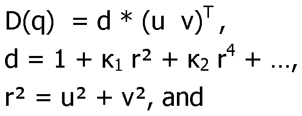
Ki , K2 , . . . are parameters defining the radial distortion in the images of the camera.
The distortion function D() radially displaces the normalized projection before it is converted to image coordinates.
Initialization steps
To calibrate camera 30, the car 100 is placed at a fixed location in front of scene A (Fig.1). S 10J. Acquisition of 3 D-coord j na tes of poi nts of the scene
First, the 3D-positions of several points M, of scene A are acquired. The points M, are preferably located so that their projections m, be evenly spread over the whole surface of the images to be acquired by camera 30. Moreover, the points M, are preferably located at various distances in depth Z from camera 30.
In first step S10, the 3D positions of N 3D-points Mi, M2... MN are measured
(only points MI-M3 are represented on Fig.l). For each point M,, its 3D-coordinates are expressed in the local coordinate frame attached to the scene, as: M, (X,, Y,,
Zj). The positions of points M, can for instance be measured with a tacheometer. S20). Acquisition of j mages of the scene with the .camera
Then, one or more images Ij (j= l..M) of the scene A are acquired by camera 30, through windshield 40. Each of these acquired images I, is such that the location of one or more point(s) Mj of the scene A can be determined in the image Ij.
As an example, Fig.3 represents image Ii acquired by camera 30, and shows 2D-points mi-m , which are the projections of points M, (i= 1,2,3), as an example of 2D-points m, formed in the image Ii.
Please note that the images Ij of the scene A can be acquired (step S20) before, after or at the same time as the 3D-coordinates of the points M, are acquired at step S10.
S30).petermjnation of jmage-based.2D-!ocations of image . points. in the. images Then, the image-based 2D-locations (Xi,yi)image of image points mUmage in the images Ij are determined. Any method can be used for this determination.
Consequently, at the end of these three steps (S10-S20-S30), for each of the 3D points M,, the following data is available:
- Coordinates (X,, U,, Z,) of 3D-point M,, and
- Coordinates (Xi,yi)image of corresponding 2D-point m, image as determined in one or more image(s).
Typically, more than 1000 points Mi are taken into account (N > 1000).
S4Q). Calculation of a n J njtjaj. model of the ca mera
Then, the 'initial model' of the camera is determined; that is, in the presently proposed embodiments, initial values of the camera parameters K, k,, R, and t which intervene in equations (5) and (6) are determined. Any known method can be used. The initial model can take into account more or less variables, to be more or less realistic, as desired. For instance, in some embodiments radial distortion is not taken into account.
The initial value of these parameters constitutes the initial model of the camera.
CAMERA CALIBRATION STEP - SPHERICAL REFRACTION
The camera calibration step of a first embodiment of a calibration method according to the present disclosure is now going to be presented. In this embodiment, to calculate the projection function, the windshield is modelled as a portion of a sphere.
Spherical refraction model
The .refraction f u nction . Ref
To take into account the refraction of light through the windshield, a refraction function 'Ref is introduced in equation (4) as follows:
(¾ ¾ Ref(p) (7)
Many functions can be envisaged for the refraction function Ref. To each function Ref corresponds a number of parameters, called 'refraction parameters', which define the effect of refraction on the light rays.
In this embodiment, since it is assumed that the windshield locally has the shape of a sphere S, the windshield is defined by the following refraction parameters: the position c of the center of sphere S, its inner radius r, its thickness d and the index n2 of its material (and optionally nl, the index of the atmosphere)(Figs.4,5). It is assumed that camera 30 is positioned inside the sphere S and that the points M, are outside the sphere. Parameters c, r, d and n2 collectively define the refraction caused by the windshield.
The . pj a ne . of refract j on . PR
In the geometry illustrated in Figure 4, p is a point of scene A under consideration, c is the center of the sphere S, and t is the center of projection of the camera 30. In general, the 3 points p, c and t define a unique plane of refraction PR that passes through each of them. For reasons of symmetry, refraction takes place in this plane, thereby reducing advantageously the 3D projection problem to a 2D problem. For the special cases where c coincides with the origin t, or when the points p, c and t are collinear, the pinhole camera can be used as is.
In the plane of refraction PR, a refraction coordinate frame is defined by its origin c, the x-axis pointing from c to t, the y-axis in the plane of refraction and perpendicular to the x-axis, and the z-axis perpendicular to the x- and y-axis, as illustrated in Figure 4.
The coordinate transformation between camera and refraction coordinates is therefore determined as follows:
The directions of the x, y and z axis in camera coordinates are determined by the equations:

in which points p, c and t are expressed in camera coordinates, and where x denotes the cross-product.
In addition, for a point v expressed in camera coordinates, the corresponding point v' in refraction coordinates is obtained as:
v' = RT (v - c) with R = (ex ey ez ) (11)
and conversely:
v = R v' + c (12)
The .projection function
To calibrate the camera, a projection function is defined beforehand. For each point p, of scene A, this function outputs a calculated projected point mi_caicuiated, that is, its calculated 2D-location (Xj,yi)Caicuiated · This function depends on the values of the refraction parameters (the position of center c of sphere S, its radius r, its thickness d, the index n2 of its material) and of the camera parameters.
In the present embodiment, considering equation (7), finding the projection of a point p through the refracting medium of sphere S comes down to finding the ray projected back from the center of projection t of the camera, which after refraction passes through that point p. Since this problem is symmetrical with respect to the plane containing the point p, the center of projection of the camera t and the center c of the sphere, it is sufficient to consider only the plane PR containing these three points. The 3D projection problem is therefore reduced to a 2D problem which can be solved iteratively.
In this purpose, we now consider the refraction of ray B through sphere S in plane PR (i.e., the XY plane), as shown in Figure 5.
p = (pi p2)T is a point that must be projected (which corresponds to point M first converted to the camera coordinate frame using equation (5), and then converted to the refraction coordinate frame using equation (11)).
t = (tl 0)T is the center of projection of the camera,
c = (0 0)T is the center of the sphere.
nl and n2 are the indices of air and of the glass of the sphere, respectively, r is the inner radius of sphere S, and
d is the thickness of sphere S.
Let (s, k), (s', k') and (s", k") be the starting points and direction vectors for each of the successive ray segments, respectively. The first ray segment originates in the center of projection of the camera t, where it makes an angle a with the x- axis, so s = t and k = [cos a; sin a]. Then, it intersects the inner sphere and is refracted. Points on the line associated with the first ray segment are given by equation:
m = s + Ak , (13)
where l parametrizes the line. The intersection of this line with the inner surface of sphere S is the positive solution for l of the quadratic equation below:
I I s + Ak 112 = R2 (14)
The starting point of the second ray segment is given by this intersection: s' = (s'i s'2)T = s + Ak. Since Q1 = a - b with b = atan2(s'2, s'i), the angle Q2 can be obtained from Snell's law of refraction since nl sin Q1 = n2 sin Q2.
The direction vector of the second ray segment is then given by:

For the ray segment exiting the outer surface of sphere S, the starting point s" and direction vector k" are obtained using similar steps.
As shown by Fig.5, a ray B comprising ray segments (s, k), (s', k) and (s", k") is entirely defined by the angle a formed between vector k and the axis x. That is, in the plane of refraction PR (Fig 4), the choice of angle a completely determines the path of ray B. Consequently, calculating the position of the point m, calculated in the image which corresponds to point p is done simply by determining the angle a of the ray B which passes through point p.
The line corresponding to the part of the ray exiting the outer surface of sphere S, and defined by the starting point s" and direction vector k", divides the refraction plane PR in two half-planes or sides. If this line passes through the point p that must be projected, the angle a has the value which is sought; otherwise, the point p is on one side or the other of this line.
To calculate the angle a of the ray B which passes through point p, a signed distance function is identified, which outputs a signed distance between the above-mentioned line (s",k") and point p. The sign of the returned value determines the side of the line on which point p is, and the absolute value gives the point-to-line distance. The root or zero-crossing of this distance function then corresponds to the value of the angle a which is looked for.
Let k" = (k"l k"2)T: The distance function f is defined as the projection of the vector (p - s") onto the direction perpendicular to k":

The regula-falsi method, or any equivalent method, is then used to find the root of f(a)=0. In Figure 5, the solution is given by ray C, which intersects the inner surface of sphere S at point P.
The point P associated with the value of a, which results from the projection of point p, can then be used to define the function Ref in equation (7) as Ref(p)=P (it should be noted that the function Ref is expected to return points expressed in the camera coordinate frame).
To summarize, the projection function is defined by the following steps, which are performed to determine the calculated image points m, calculated based on the value of the 3D-points Mi:
For each point Mi:
- Convert the 3D-coordinates of the point Mi to the camera coordinate frame, using equation (5);
- Convert the resulting point p to the refraction coordinate frame using equation (11);
- Find the root of equation f(a)=0, and the associated point P;
- Convert the point P to the camera coordinate frame using equation (12);
- With Ref(p)=P (in camera coordinates, see previous step), apply equation (7) to obtain the normalized projection q; and
- Calculate m, calculated by applying equation (6). S50) Calculation of the final model of the camera
For the last calculation step S50, the values of the camera model determined at step S40 as used as initial values for the values of the parameters of the camera; namely in the present exemplary embodiment, parameters K, k,, R, t, which intervene in equation (6).
Then, the values of the various parameters of the model, which include both the camera parameters, and the refraction parameters, are determined iteratively using the following method.
For each 3D point M,, a value of its projection (2D-point m,) is calculated using the above-described projection function. More specifically, for any point M,, the value of the angle a which corresponds to point M, is calculated using the above-described function. Once a has been calculated, the corresponding calculated 2D-point can be readily calculated.
Consequently, for each 3D point M,, the following data is available:
- 3D-point coordinates (X,, Y,, ¾),
- Corresponding 2D-point m, jmage coordinates (Xi,yi)image as determined in the image, and
- Corresponding 2D-point m, calculated coordinates (Xi,yi)Caicuiated as calculated using the projection routine described above.
Based on this data, the value of the error function E can be calculated:
Eprojection
 dist ( mjjmage, rnj_caiculated) 2
This error function Epr0jection is then minimized.
Any suitable minimization algorithm can be used. For instance, in the present embodiment, the Levenberg-Marquardt algorithm is used. Such algorithm is readily available in computing packages such as Matlab (Registered trademark).
Typically, optimization or minimization packages need to evaluate the value and the derivatives of each term in the error function at arbitrary parameter values, so the iterative nature of the above-described projection function might present as a problem. However, optimization packages that use automatic differentiation techniques, such as Ceres (Registered trademark), can automatically evaluate the derivative of a function specified by a computer program.
By running the minimization algorithm, the various refraction parameters involved in the projection function are determined: the camera parameters K, k,,
R, and t involved in equation (5) and (6), as well as the refraction parameters: location of the center c of the sphere, n2 index of the glass of the sphere, r and d the inner radius and the thickness of sphere S. Accordingly, the projection function is fully determined, whereby the calibration of the camera is completed.
The model of the camera so identified can be used in various ways.
It can be used in particular to calculate corrected position values of regions of interest identified in images acquired by the camera. The camera model makes it possible to calculate corrected positions which compensate for the refracting effect of the windshield in front of the camera.
CAMERA CALIBRATION STEP - SPLINE REFRACTION
In the first embodiment, a simple spherical model has been assumed for the windshield, making it possible to obtain a formula for the projection function relatively simply, using a small number of refraction parameters.
In a second embodiment, as explained in more details below, the projection function is mainly defined by two sets of spline patches, as shown schematically on Fig.6. Fig.6 shows the weighted combination of two or multiple splines generated for different depths. For instance, these splines can be 2D splines that
model the shift of the projection of point p in image space due to refraction caused by the windshield.
Spline refraction model
The .ref faction f u nction . Ref
Let p = [X Y Z]T be a 3D point that must be projected, expressed in camera coordinates. If refraction is ignored, the normalized projection q0 of this point is given by:
(¾ ¾ P (16)
The actual projection q taking into account refraction is then defined by introducing a correction Aq to the projection q0 such that q=qo+Aq, and which allows to define the refraction function Ref from equation (7) as follows:

where the correction DV is a displacement in the normalized image plane due to refraction. The correction DV is a function of the point p, or equivalently, the projection q0 and depth Z.
Consequently, based on equation (6), it is concluded that:

The correction term Dq will be approximated by a model based on splines.
But beforehand, to simplify this model it is first assumed that, for a projected point qo, the corrections for different depths form a line parametrized by inverse depth. So, for a projected point qo, the parameters of the line joining two points can be calculated simply based on the correction values at two different depths.
For this reason, to calculate the function Aq(q0,Z), it seems necessary to evaluate Aq(q0,Z) for two different depths Z1 and Z2, so as to obtain the correction values at two different depths, namely Aql(q0) = Aq(q0,Zl) and Aq2(q0) = Aq(q0,Z2).
Consequently, based on these assumptions, the correction Aq(q0, Z) is approximated as:
Aql(qo)
Aq(qo, Z)
 where Aql(q0) and Aq2(q0) are defined over the normalized image only.
The above equation 18 describes the weighting for two splines created for depths Z1 and Z2. However, since Aq(q0, Z) is not available, Aql(q0) and Aq2(q0) have to be modelled, and are modelled by two spline-based functions fl(qo;01) and f2(qo;02), respectively: the values of the parameters 01 and 02 (which are the parameters of the spline patches) will be optimized by the procedure presented below.
Accordingly, the final spline-based refraction function is defined by the following equations: r(q, Z) X Aq(q, Z)
Ref

where the corrective term r(q0,Z) is given by:

In this implementation, Z1 = 1 and Z2 = +¥ are arbitrarily selected.
Sp.line . representation
With q = [u v]T being the normalized projection of a 3D point p, each of the spline-based functions fl(q) and f2(q) from the previous section has two components.
Let the function s(q), or s(u, v), denote one of these two components.
The function s(u, v) is modelled by a 2D grid of connected bicubic spline patches, where neighbouring patches share function values and derivates at their corners to ensure continuity across patches.
In order to evaluate a value s(u,v), the patch which corresponds to the selected value of (u,v) must first be selected, based on the coordinates u and v.
Then, the value of s(u,v) is calculated by using the bicubic patch function p of the selected patch. This patch function p takes the following form:
p(u,v) = [u3 u2 u 1]T C [v3 v2 v 1] (21)
with
ell cl2 cl3 cl4\
c = c21 c22 c23 c24 I
c31 c32 c33 c34 / (22)
c41 c42 c43 c44/
The coefficients of the matrix C are completely determined by the function values s and the derivatives 3s/3x, 3s/3y, and 32s/3x3y stored at the four corners of the patch. Indeed, matching the function p(u, v) with these values yields 16 linear equations in the 16 coefficients. Since the function values and derivates are shared across patches, they completely determine the function s(u, v) as well, and can therefore be used as parameters in an optimization.
Furthermore, there is also an inherent sparse structure that can be exploited during optimization since each evaluation of s(u,v) only interacts with a single patch.
Because the above spline representation has many parameters, it can be prone to overfitting, so regularization is necessary in order to determine the parameters of the C matrices. In order to enforce some smoothness, a so-called "thin-plate constraint" is used. The thin-plate energy for a single patch p(u, v) can written as:

E = zTA z (24)
where z is a 16-vector that holds the function values and derivatives of the four corners of the patch, and A is a fixed 16 x 16 symmetric positive semidefinite matrix.
The thin-plate energy Ethinpiate for the function p(u, v) is then the sum of energies E of all patches. The role of this function Ethinpiate will be explained later. The. projection subroutine
Based on the model of the refraction function Ref presented aboved, the projection routine involved for determining the calculated image points m, calculated, based on the value of the 3D-points Mi can now be defined. For each point Mi, the following steps must be carried out:
- Convert the point Mi to the camera coordinate frame using equation (5), which provides the point p = [X Y Z]T
- Compute the normalized projection q0 of point p using equation (16)
- Evaluate the spline functions fl(qo;01) and f2(qo;02). (for each evaluation, since each bi-cubic patch covers only a part of the normalized image plane, it is necessary to select the appropriate patch based on the coordinates of q0)
- On the basis of fl(qo;01), f2(qo;02) and Z, the corrective term r(q0, Z) is thus determined using equation (20)
- The normalized projection q is then calculated based on the equation: q=qo+r(q0, Z)
- The projected point m, calculated and its coordinates (Xi,yi)caicuiated are finally obtained by applying equation (6).
S50) Calculation of the final model of the camera
The final model of the camera is calculated substantially as in the first embodiment, except that, since refraction is modelled quite differently, using different parameters, the projection subroutine is totally different, as explained above.
Initial values are set for the respective values of the parameters. In particular, these initial values can be values of the camera model which have been determined as the final camera parameters using the spherical refraction model; namely in the present exemplary embodiment, parameters K, k,, R, t, which intervene in equation (5) and (6).
In addition, as initial values, all the parameters of the matrices Ck are set to
0.
Then, the values of the various refraction parameters of the spline-based model are determined iteratively by minimising an error function E, as in the first embodiment. Here, the distance based energy function Epr0jection used in the first embodiment is augmented with a thin-plate energy term Expiate that favours smooth spline functions in order to prevent overfitting. So, the total energy to be minimized is given by:

The meta-parameter l is determined automatically to find the optimal balance between fitting the data and favouring smooth solutions. This is done by partitioning the data set in a training set and a test set. The above energy function E is then optimized using the training set for a range of l values, and
evaluated on the test set (not used in the optimization). When evaluated on the test set, the lowest value for the error Epr0jection identifies the optimal value for l.
Claims
1. A method for calibrating a camera (30) mounted behind a transparent wall (40) so as to obtain a projection function of the camera;
said projection function receiving coordinates of a point (Mi) of the scene (A) as an input, and providing a calculated 2D-location ((Xj,yj)Caicuiated) of a projection of the point (Mi) in an image (Ii) of the scene as an output;
wherein the method comprises:
S30) based on at least one image (Ii) of the scene (A) acquired by the camera (30) through the transparent wall (40), determining image-based 2D- locations ((Xi,yi)image) of image points (mUmage) in said at least one acquired image (Ii), the image points (miimage) corresponding to said points (Mi) of the scene; and, the projection function being determined as a function of at least one refraction parameter;
S50) calculating the value of said at least one refraction parameter by minimizing an error function (E);
the error function being a function of said at least one refraction parameter; and
the error function (E) including a projection error (Epr0jection) function of distances between said image-based 2D-locations ((Xi,yi)image) and calculated 20- locations ((Xi,yi)caicuiated) obtained by applying the projection function to the points (Mi) of the scene.
2. A method for calibrating a camera according to claim 1, wherein the method further comprises:
S40) calculating an initial projection function of the camera between the points of the scene and the camera on the basis of said at least one acquired image (Ii); and
at step S50), the value of said at least one refraction parameter is calculated iteratively, taking into account refraction caused by the transparent wall (40); the iterative algorithm being initialized with the initial projection function of the camera.
3. A method for calibrating a camera according to claim 1 or 2 in which said at least one refraction parameter includes a radius of a sphere, the transparent wall (40) being thus modelled locally as a sphere (S).
4. A method for calibrating a camera according to claim 3, in which said calculated 2D-location ((Xj,yj)caicuiated) of a point of the scene is calculated using the projection function on the basis of a plane of refraction (PR) which contains a 3D point of the scene (A) under consideration, a center (c) of the sphere (S), the sphere being defined by a radius (r) and a thickness (d), and a center (t) of projection of the camera (30).
5. A method for calibrating a camera according to claim 4, in which said calculated 2D-location of a point of the scene is calculated by calculating a value of an angle (a) formed relative to a line joining the center (c) of the sphere (S) to an optical center (t) of the camera (30) by a ray in the plane of refraction (PR) which is projected from a point (Mi) of the scene under consideration to the optical center (t) of the camera (30).
6. A method for calibrating a camera according to any one of claims 1 to 5 in which said at least one refraction parameter includes an index (n2) of a material of the transparent wall.
7. A method for calibrating a camera according to claim 1 or 2, in which said calculated 2D-locations ((Xi,yi)caicuiated) of points (Mi) of the scene are calculated using an additive correction function (Aq(p,Z)) which outputs a displacement in a normalized image plane due to refraction based on 3D- coordinates of a point (Mi) of the scene and a depth (Z) of said point in the scene, whereby the calculated 2D-locations ((Xj,yj)caicuiated) are calculated based on the sum of 2D-coordinates (qT) calculated without the additive correction and a corrective term (Aq(q, Z)T) obtained with said correction function.
8. A method for calibrating a camera according to claim 7, in which said correction function is a function (Aq(q,Z)) of an inverse of the depth (Z).
9. A method for calibrating a camera according to claim 7 or 8, in which parameters of said correction function (Aq(q,Z)) are defined by two functions (fl,f2), each of said function being defined by a set of spline surfaces continuously connected to each other.
10. A method for calibrating a camera according to claim 9, in which the error function (E) includes a regularization term (Ethinplate) constraining the derivatives of the said spline surfaces.
11. A computer program which is stored on a computer readable storage medium, and which is suitable for being performed on a computer, the program including instructions adapted to perform the steps of a method according to any one of claims 1 to 9 when it is run on the computer.
12. A computer-readable recording medium including instructions of a computer program according to claim 10.
13. A camera calibration system for calibrating at least one camera (30) mounted behind a transparent wall (40) so as to obtain a projection function of the camera;
said projection function receiving coordinates of a point (Mi) of a scene (A) as an input, and providing a calculated 2D-location ((Xj,yj)caicuiated) of a projection of the point (Mi) in an image (Ii) of the scene as an output;
the camera calibration system comprising a computer (20) configured to: S10) acquire a plurality of 3D-coordinates of points of a scene (A);
S20) acquire at least one image (Ii) of the scene (A) captured with a first camera (30) to be calibrated through the transparent wall (40);
S30) based on at least one image (Ii) of the scene (A) acquired by the camera (30) through the transparent wall (40), determine image-based 2D- locations of image points (mUmage) in said at least one acquired image (Ii);
the image points (miimage) corresponding to said points (Mi) of the scene; and, the projection function being determined as a function of at least one refraction parameter;
S50) calculate the value of said at least one refraction parameter by minimizing an error function (E);
the error function being a function of said at least one refraction parameter;
the error function (E) including a projection error (Epr0jection) function of distances between said image-based 2D-locations ((Xi,yi)image) and calculated 2D- locations ((Xj,yj)caicuiated) obtained by applying the projection function to the 3D- coordinates of said points (Mi) of the scene.
14. The camera calibration system according to claim 13, wherein the computer is configured to calculate an initial projection function of the camera between the points of the scene and the camera on the basis of said at least one acquired image (Ii); and to calculate the value of said at least one refraction parameter iteratively, taking into account refraction caused by the transparent wall (40), the iterative algorithm being initialized with the initial projection function of the camera.
15. The camera calibration system according to claim 13 or 14, wherein said at least one refraction parameter includes a radius of a sphere, the transparent wall (40) being thus modelled locally as a sphere (S).
16. The camera calibration system according to claim 15, wherein the computer is configured to calculate said calculated 2D-location ((Xj,yj)Caicuiated) of a point of the scene using the projection function on the basis of a plane of refraction (PR) which contains a 3D point of the scene (A) under consideration, a center (c) of the sphere (S), the sphere being defined by a radius (r) and a thickness (d), and a center (t) of projection of the camera (30).
17. The camera calibration system according to claim 16, wherein the computer is configured to calculate said calculated 2D-location of a point of the scene by calculating a value of an angle (a) formed relative to a line joining the center (c) of the sphere (S) to an optical center (t) of the camera (30) by a ray in the plane of refraction (PR) which is projected from a point (Mi) of the scene under consideration to the optical center (t) of the camera (30).
18. The camera calibration system according to any one of claims 13 to 17, wherein said at least one refraction parameter includes an index (n2) of a material of the transparent wall.
19. The camera calibration system according to claim 13 or 14, wherein the computer is configured to calculate said calculated 2D-locations ((Xj,yj)caicuiated) of points (Mi) of the scene using an additive correction function (Aq(p,Z)) which outputs a displacement in a normalized image plane due to refraction based on 3D-coordinates of a point (Mi) of the scene and a depth (Z) of said point in the scene, whereby the calculated 2D-locations ((Xj,yj)caicuiated) are calculated based on
the sum of 2D-coordinates (qT) calculated without the additive correction and a corrective term (Aq(q, Z)T) obtained with said correction function.
20. The camera calibration system according to claim 19, wherein said correction function is a function (Aq(q,Z)) of an inverse of the depth (Z).
21. The camera calibration system according to claim 19 or 20, wherein parameters of said correction function (Aq(q,Z)) are defined by two functions (fl,f2), each of said functions being defined by a set of spline surfaces continuously connected to each other.
22. The camera calibration system according to claim 21, wherein the error function (E) includes a regularization term (Ethinplate) constraining the derivatives of said spline surfaces.
Priority Applications (1)
| Application Number | Priority Date | Filing Date | Title |
|---|---|---|---|
| PCT/EP2019/068763 WO2021004642A1 (en) | 2019-07-11 | 2019-07-11 | A camera calibration method, a computer program, a computer-readable recording medium and a camera calibration system |
Applications Claiming Priority (1)
| Application Number | Priority Date | Filing Date | Title |
|---|---|---|---|
| PCT/EP2019/068763 WO2021004642A1 (en) | 2019-07-11 | 2019-07-11 | A camera calibration method, a computer program, a computer-readable recording medium and a camera calibration system |
Publications (1)
| Publication Number | Publication Date |
|---|---|
| WO2021004642A1 true WO2021004642A1 (en) | 2021-01-14 |
Family
ID=67514583
Family Applications (1)
| Application Number | Title | Priority Date | Filing Date |
|---|---|---|---|
| PCT/EP2019/068763 Ceased WO2021004642A1 (en) | 2019-07-11 | 2019-07-11 | A camera calibration method, a computer program, a computer-readable recording medium and a camera calibration system |
Country Status (1)
| Country | Link |
|---|---|
| WO (1) | WO2021004642A1 (en) |
Cited By (2)
| Publication number | Priority date | Publication date | Assignee | Title |
|---|---|---|---|---|
| CN115797468A (en) * | 2023-02-03 | 2023-03-14 | 厦门农芯数字科技有限公司 | Method, device and equipment for automatic correction of installation height of fisheye camera |
| WO2023104254A1 (en) * | 2021-12-09 | 2023-06-15 | Continental Autonomous Mobility Germany GmbH | Dynamic autocalibration of a vehicle camera system behind a windshield |
Citations (3)
| Publication number | Priority date | Publication date | Assignee | Title |
|---|---|---|---|---|
| WO2015133414A1 (en) * | 2014-03-07 | 2015-09-11 | Ricoh Company, Limited | Calibrarion method, calibration device, and computer program product |
| EP3293701A1 (en) * | 2016-09-07 | 2018-03-14 | Conti Temic microelectronic GmbH | Method and apparatus for the compensation of static image distortions introduced by a windshield onto an adas camera |
| EP3505865A1 (en) * | 2016-08-29 | 2019-07-03 | Hitachi Automotive Systems, Ltd. | On-vehicle camera, method for adjusting on-vehicle camera, and on-vehicle camera system |
-
2019
- 2019-07-11 WO PCT/EP2019/068763 patent/WO2021004642A1/en not_active Ceased
Patent Citations (3)
| Publication number | Priority date | Publication date | Assignee | Title |
|---|---|---|---|---|
| WO2015133414A1 (en) * | 2014-03-07 | 2015-09-11 | Ricoh Company, Limited | Calibrarion method, calibration device, and computer program product |
| EP3505865A1 (en) * | 2016-08-29 | 2019-07-03 | Hitachi Automotive Systems, Ltd. | On-vehicle camera, method for adjusting on-vehicle camera, and on-vehicle camera system |
| EP3293701A1 (en) * | 2016-09-07 | 2018-03-14 | Conti Temic microelectronic GmbH | Method and apparatus for the compensation of static image distortions introduced by a windshield onto an adas camera |
Cited By (6)
| Publication number | Priority date | Publication date | Assignee | Title |
|---|---|---|---|---|
| WO2023104254A1 (en) * | 2021-12-09 | 2023-06-15 | Continental Autonomous Mobility Germany GmbH | Dynamic autocalibration of a vehicle camera system behind a windshield |
| JP2024542542A (en) * | 2021-12-09 | 2024-11-15 | コンチネンタル・オートナマス・モビリティ・ジャーマニー・ゲゼルシャフト・ミト・ベシュレンクテル・ハフツング | Dynamic Auto-Calibration of Behind-Glass Vehicle Camera Systems |
| US12437444B2 (en) | 2021-12-09 | 2025-10-07 | Continental Autonomous Mobility Germany GmbH | Dynamic autocalibration of a vehicle camera system behind a windshield |
| JP7778928B2 (en) | 2021-12-09 | 2025-12-02 | オーモヴィオ・オートノモス・モビリティー・ジャーマニー・ゲゼルシャフト・ミト・ベシュレンクテル・ハフツング | Dynamic Auto-Calibration of Behind-the-Wind Vehicle Camera Systems |
| CN115797468A (en) * | 2023-02-03 | 2023-03-14 | 厦门农芯数字科技有限公司 | Method, device and equipment for automatic correction of installation height of fisheye camera |
| CN115797468B (en) * | 2023-02-03 | 2023-05-16 | 厦门农芯数字科技有限公司 | Automatic correction method, device and equipment for installation height of fish-eye camera |
Similar Documents
| Publication | Publication Date | Title |
|---|---|---|
| CN110599578B (en) | A realistic 3D color texture reconstruction method | |
| US11861813B2 (en) | Image distortion correction method and apparatus | |
| CN108257183B (en) | Method and device for calibrating optical axis of camera lens | |
| CN106875339B (en) | Fisheye image splicing method based on strip-shaped calibration plate | |
| JP6576945B2 (en) | Calibration apparatus, calibration method, optical apparatus, photographing apparatus, projection apparatus, measurement system, and measurement method | |
| US11403739B2 (en) | Methods and apparatus for retargeting and prioritized interpolation of lens profiles | |
| Douxchamps et al. | High-accuracy and robust localization of large control markers for geometric camera calibration | |
| CN113793266A (en) | Multi-view machine vision image splicing method, system and storage medium | |
| JP2021503133A (en) | Systems and methods for exogenous calibration of cameras and diffractive optics | |
| CN108520537A (en) | A Binocular Depth Acquisition Method Based on Photometric Parallax | |
| JP7489253B2 (en) | Depth map generating device and program thereof, and depth map generating system | |
| CN108629756A (en) | A kind of Kinect v2 depth images Null Spot restorative procedure | |
| CN104778656A (en) | Fisheye image correction method on basis of spherical perspective projection | |
| CN117237789A (en) | Method for generating texture information point cloud map based on fusion of panoramic camera and lidar | |
| US20240046575A1 (en) | Video See-Through Augmented Reality | |
| CN110619660A (en) | Object positioning method and device, computer readable storage medium and robot | |
| Perdigoto et al. | Calibration of mirror position and extrinsic parameters in axial non-central catadioptric systems | |
| CN117197241A (en) | A high-precision tracking method for robot end absolute pose based on multi-eye vision | |
| CN119887514A (en) | Panoramic image stitching method, device, equipment and medium | |
| CN115375775A (en) | Underwater camera calibration method and device based on forward projection refraction model | |
| WO2021004642A1 (en) | A camera calibration method, a computer program, a computer-readable recording medium and a camera calibration system | |
| Deng et al. | Self-Calibrating Gaussian Splatting for Large Field-of-View Reconstruction | |
| CN107341766A (en) | A kind of image automatic debugging system of panoramic parking assist system, method and apparatus | |
| Wu et al. | Unsupervised texture reconstruction method using bidirectional similarity function for 3-D measurements | |
| US12526526B1 (en) | Image compositing with adjacent low parallax cameras |
Legal Events
| Date | Code | Title | Description |
|---|---|---|---|
| 121 | Ep: the epo has been informed by wipo that ep was designated in this application |
Ref document number: 19748731 Country of ref document: EP Kind code of ref document: A1 |
|
| 122 | Ep: pct application non-entry in european phase |
Ref document number: 19748731 Country of ref document: EP Kind code of ref document: A1 |