WO2021000941A1 - 基于脉搏波传导时间的胸口无创血压检测探头及其装置 - Google Patents
基于脉搏波传导时间的胸口无创血压检测探头及其装置 Download PDFInfo
- Publication number
- WO2021000941A1 WO2021000941A1 PCT/CN2020/100155 CN2020100155W WO2021000941A1 WO 2021000941 A1 WO2021000941 A1 WO 2021000941A1 CN 2020100155 W CN2020100155 W CN 2020100155W WO 2021000941 A1 WO2021000941 A1 WO 2021000941A1
- Authority
- WO
- WIPO (PCT)
- Prior art keywords
- electrode
- blood pressure
- signal
- pulse wave
- transit time
- Prior art date
- Legal status (The legal status is an assumption and is not a legal conclusion. Google has not performed a legal analysis and makes no representation as to the accuracy of the status listed.)
- Ceased
Links
Images






Classifications
-
- A—HUMAN NECESSITIES
- A61—MEDICAL OR VETERINARY SCIENCE; HYGIENE
- A61B—DIAGNOSIS; SURGERY; IDENTIFICATION
- A61B5/00—Measuring for diagnostic purposes; Identification of persons
- A61B5/0059—Measuring for diagnostic purposes; Identification of persons using light, e.g. diagnosis by transillumination, diascopy, fluorescence
-
- A—HUMAN NECESSITIES
- A61—MEDICAL OR VETERINARY SCIENCE; HYGIENE
- A61B—DIAGNOSIS; SURGERY; IDENTIFICATION
- A61B5/00—Measuring for diagnostic purposes; Identification of persons
- A61B5/02—Detecting, measuring or recording for evaluating the cardiovascular system, e.g. pulse, heart rate, blood pressure or blood flow
- A61B5/026—Measuring blood flow
- A61B5/0261—Measuring blood flow using optical means, e.g. infrared light
-
- A—HUMAN NECESSITIES
- A61—MEDICAL OR VETERINARY SCIENCE; HYGIENE
- A61B—DIAGNOSIS; SURGERY; IDENTIFICATION
- A61B5/00—Measuring for diagnostic purposes; Identification of persons
- A61B5/02—Detecting, measuring or recording for evaluating the cardiovascular system, e.g. pulse, heart rate, blood pressure or blood flow
- A61B5/0205—Simultaneously evaluating both cardiovascular conditions and different types of body conditions, e.g. heart and respiratory condition
-
- A—HUMAN NECESSITIES
- A61—MEDICAL OR VETERINARY SCIENCE; HYGIENE
- A61B—DIAGNOSIS; SURGERY; IDENTIFICATION
- A61B5/00—Measuring for diagnostic purposes; Identification of persons
- A61B5/02—Detecting, measuring or recording for evaluating the cardiovascular system, e.g. pulse, heart rate, blood pressure or blood flow
- A61B5/021—Measuring pressure in heart or blood vessels
- A61B5/02108—Measuring pressure in heart or blood vessels from analysis of pulse wave characteristics
- A61B5/02125—Measuring pressure in heart or blood vessels from analysis of pulse wave characteristics of pulse wave propagation time
-
- A—HUMAN NECESSITIES
- A61—MEDICAL OR VETERINARY SCIENCE; HYGIENE
- A61B—DIAGNOSIS; SURGERY; IDENTIFICATION
- A61B5/00—Measuring for diagnostic purposes; Identification of persons
- A61B5/02—Detecting, measuring or recording for evaluating the cardiovascular system, e.g. pulse, heart rate, blood pressure or blood flow
- A61B5/026—Measuring blood flow
- A61B5/0295—Measuring blood flow using plethysmography, i.e. measuring the variations in the volume of a body part as modified by the circulation of blood therethrough, e.g. impedance plethysmography
-
- A—HUMAN NECESSITIES
- A61—MEDICAL OR VETERINARY SCIENCE; HYGIENE
- A61B—DIAGNOSIS; SURGERY; IDENTIFICATION
- A61B5/00—Measuring for diagnostic purposes; Identification of persons
- A61B5/103—Measuring devices for testing the shape, pattern, colour, size or movement of the body or parts thereof, for diagnostic purposes
- A61B5/11—Measuring movement of the entire body or parts thereof, e.g. head or hand tremor or mobility of a limb
- A61B5/1102—Ballistocardiography
-
- A—HUMAN NECESSITIES
- A61—MEDICAL OR VETERINARY SCIENCE; HYGIENE
- A61B—DIAGNOSIS; SURGERY; IDENTIFICATION
- A61B5/00—Measuring for diagnostic purposes; Identification of persons
- A61B5/24—Detecting, measuring or recording bioelectric or biomagnetic signals of the body or parts thereof
- A61B5/25—Bioelectric electrodes therefor
- A61B5/251—Means for maintaining electrode contact with the body
- A61B5/257—Means for maintaining electrode contact with the body using adhesive means, e.g. adhesive pads or tapes
- A61B5/259—Means for maintaining electrode contact with the body using adhesive means, e.g. adhesive pads or tapes using conductive adhesive means, e.g. gels
-
- A—HUMAN NECESSITIES
- A61—MEDICAL OR VETERINARY SCIENCE; HYGIENE
- A61B—DIAGNOSIS; SURGERY; IDENTIFICATION
- A61B5/00—Measuring for diagnostic purposes; Identification of persons
- A61B5/24—Detecting, measuring or recording bioelectric or biomagnetic signals of the body or parts thereof
- A61B5/25—Bioelectric electrodes therefor
- A61B5/263—Bioelectric electrodes therefor characterised by the electrode materials
- A61B5/265—Bioelectric electrodes therefor characterised by the electrode materials containing silver or silver chloride
-
- A—HUMAN NECESSITIES
- A61—MEDICAL OR VETERINARY SCIENCE; HYGIENE
- A61B—DIAGNOSIS; SURGERY; IDENTIFICATION
- A61B5/00—Measuring for diagnostic purposes; Identification of persons
- A61B5/24—Detecting, measuring or recording bioelectric or biomagnetic signals of the body or parts thereof
- A61B5/25—Bioelectric electrodes therefor
- A61B5/263—Bioelectric electrodes therefor characterised by the electrode materials
- A61B5/266—Bioelectric electrodes therefor characterised by the electrode materials containing electrolytes, conductive gels or pastes
-
- A—HUMAN NECESSITIES
- A61—MEDICAL OR VETERINARY SCIENCE; HYGIENE
- A61B—DIAGNOSIS; SURGERY; IDENTIFICATION
- A61B5/00—Measuring for diagnostic purposes; Identification of persons
- A61B5/24—Detecting, measuring or recording bioelectric or biomagnetic signals of the body or parts thereof
- A61B5/25—Bioelectric electrodes therefor
- A61B5/263—Bioelectric electrodes therefor characterised by the electrode materials
- A61B5/27—Conductive fabrics or textiles
-
- A—HUMAN NECESSITIES
- A61—MEDICAL OR VETERINARY SCIENCE; HYGIENE
- A61B—DIAGNOSIS; SURGERY; IDENTIFICATION
- A61B5/00—Measuring for diagnostic purposes; Identification of persons
- A61B5/24—Detecting, measuring or recording bioelectric or biomagnetic signals of the body or parts thereof
- A61B5/25—Bioelectric electrodes therefor
- A61B5/279—Bioelectric electrodes therefor specially adapted for particular uses
- A61B5/28—Bioelectric electrodes therefor specially adapted for particular uses for electrocardiography [ECG]
-
- A—HUMAN NECESSITIES
- A61—MEDICAL OR VETERINARY SCIENCE; HYGIENE
- A61B—DIAGNOSIS; SURGERY; IDENTIFICATION
- A61B5/00—Measuring for diagnostic purposes; Identification of persons
- A61B5/24—Detecting, measuring or recording bioelectric or biomagnetic signals of the body or parts thereof
- A61B5/316—Modalities, i.e. specific diagnostic methods
- A61B5/318—Heart-related electrical modalities, e.g. electrocardiography [ECG]
- A61B5/332—Portable devices specially adapted therefor
-
- A—HUMAN NECESSITIES
- A61—MEDICAL OR VETERINARY SCIENCE; HYGIENE
- A61B—DIAGNOSIS; SURGERY; IDENTIFICATION
- A61B5/00—Measuring for diagnostic purposes; Identification of persons
- A61B5/24—Detecting, measuring or recording bioelectric or biomagnetic signals of the body or parts thereof
- A61B5/316—Modalities, i.e. specific diagnostic methods
- A61B5/318—Heart-related electrical modalities, e.g. electrocardiography [ECG]
- A61B5/346—Analysis of electrocardiograms
- A61B5/349—Detecting specific parameters of the electrocardiograph cycle
- A61B5/352—Detecting R peaks, e.g. for synchronising diagnostic apparatus; Estimating R-R interval
-
- A—HUMAN NECESSITIES
- A61—MEDICAL OR VETERINARY SCIENCE; HYGIENE
- A61B—DIAGNOSIS; SURGERY; IDENTIFICATION
- A61B5/00—Measuring for diagnostic purposes; Identification of persons
- A61B5/68—Arrangements of detecting, measuring or recording means, e.g. sensors, in relation to patient
- A61B5/6801—Arrangements of detecting, measuring or recording means, e.g. sensors, in relation to patient specially adapted to be attached to or worn on the body surface
- A61B5/6813—Specially adapted to be attached to a specific body part
- A61B5/6823—Trunk, e.g., chest, back, abdomen, hip
-
- A—HUMAN NECESSITIES
- A61—MEDICAL OR VETERINARY SCIENCE; HYGIENE
- A61B—DIAGNOSIS; SURGERY; IDENTIFICATION
- A61B5/00—Measuring for diagnostic purposes; Identification of persons
- A61B5/68—Arrangements of detecting, measuring or recording means, e.g. sensors, in relation to patient
- A61B5/6801—Arrangements of detecting, measuring or recording means, e.g. sensors, in relation to patient specially adapted to be attached to or worn on the body surface
- A61B5/683—Means for maintaining contact with the body
- A61B5/6832—Means for maintaining contact with the body using adhesives
- A61B5/6833—Adhesive patches
-
- A—HUMAN NECESSITIES
- A61—MEDICAL OR VETERINARY SCIENCE; HYGIENE
- A61B—DIAGNOSIS; SURGERY; IDENTIFICATION
- A61B5/00—Measuring for diagnostic purposes; Identification of persons
- A61B5/72—Signal processing specially adapted for physiological signals or for diagnostic purposes
-
- A—HUMAN NECESSITIES
- A61—MEDICAL OR VETERINARY SCIENCE; HYGIENE
- A61B—DIAGNOSIS; SURGERY; IDENTIFICATION
- A61B2503/00—Evaluating a particular growth phase or type of persons or animals
- A61B2503/10—Athletes
-
- A—HUMAN NECESSITIES
- A61—MEDICAL OR VETERINARY SCIENCE; HYGIENE
- A61B—DIAGNOSIS; SURGERY; IDENTIFICATION
- A61B2505/00—Evaluating, monitoring or diagnosing in the context of a particular type of medical care
- A61B2505/07—Home care
-
- A—HUMAN NECESSITIES
- A61—MEDICAL OR VETERINARY SCIENCE; HYGIENE
- A61B—DIAGNOSIS; SURGERY; IDENTIFICATION
- A61B2505/00—Evaluating, monitoring or diagnosing in the context of a particular type of medical care
- A61B2505/09—Rehabilitation or training
-
- A—HUMAN NECESSITIES
- A61—MEDICAL OR VETERINARY SCIENCE; HYGIENE
- A61B—DIAGNOSIS; SURGERY; IDENTIFICATION
- A61B2560/00—Constructional details of operational features of apparatus; Accessories for medical measuring apparatus
- A61B2560/02—Operational features
- A61B2560/0204—Operational features of power management
- A61B2560/0209—Operational features of power management adapted for power saving
-
- A—HUMAN NECESSITIES
- A61—MEDICAL OR VETERINARY SCIENCE; HYGIENE
- A61B—DIAGNOSIS; SURGERY; IDENTIFICATION
- A61B2562/00—Details of sensors; Constructional details of sensor housings or probes; Accessories for sensors
- A61B2562/02—Details of sensors specially adapted for in-vivo measurements
- A61B2562/0209—Special features of electrodes classified in A61B5/24, A61B5/25, A61B5/283, A61B5/291, A61B5/296, A61B5/053
- A61B2562/0215—Silver or silver chloride containing
-
- A—HUMAN NECESSITIES
- A61—MEDICAL OR VETERINARY SCIENCE; HYGIENE
- A61B—DIAGNOSIS; SURGERY; IDENTIFICATION
- A61B2562/00—Details of sensors; Constructional details of sensor housings or probes; Accessories for sensors
- A61B2562/02—Details of sensors specially adapted for in-vivo measurements
- A61B2562/0219—Inertial sensors, e.g. accelerometers, gyroscopes, tilt switches
-
- A—HUMAN NECESSITIES
- A61—MEDICAL OR VETERINARY SCIENCE; HYGIENE
- A61B—DIAGNOSIS; SURGERY; IDENTIFICATION
- A61B2562/00—Details of sensors; Constructional details of sensor housings or probes; Accessories for sensors
- A61B2562/16—Details of sensor housings or probes; Details of structural supports for sensors
- A61B2562/164—Details of sensor housings or probes; Details of structural supports for sensors the sensor is mounted in or on a conformable substrate or carrier
Definitions
- the invention belongs to the field of non-invasive blood pressure monitoring equipment, and specifically relates to a chest non-invasive blood pressure detection probe based on pulse wave transit time and a device thereof.
- Blood pressure is one of the important physiological parameters reflecting the cardiovascular status of the human body. Human blood pressure is fluctuating. Continuous non-invasive blood pressure measurement can detect arterial blood pressure on a beat-by-beat basis, which is helpful for the prevention, diagnosis, treatment and control of cardiovascular diseases.
- the current non-invasive blood pressure detection technology is roughly divided into intermittent measurement and continuous measurement. Intermittent measurement methods include auscultation method and oscillometric method, which have the characteristics of high accuracy, but require high operators and can only obtain intermittent blood pressure values.
- Continuous measurement methods include arterial tension method, volume compensation method and pulse wave velocity method. Although the arterial tension method and the volume compensation method are relatively mature, they are sensitive to the position of the sensor and cause venous congestion due to long-term measurement, which makes users feel uncomfortable.
- the pulse wave velocity correlation method has become a research hotspot in recent years due to its advantages of non-interference and dynamic measurement.
- the traditional blood pressure detection method based on pulse wave transit time has the problems that it can only measure a single blood pressure indicator, needs frequent calibration, and has poor accuracy.
- One of the reasons for this problem is that traditional methods ignore the influence of vasoconstriction and relaxation ability and PEP in the pre-ejection period on blood pressure fluctuations, and only rely on a single parameter of PTT to estimate blood pressure, and cannot track ambulatory blood pressure for a long time.
- the traditional methods are usually located on the wrist, fingers, limbs, etc., which will cause the measured pulse wave transit time to include not only the aortic pulse wave transit time that is linearly related to blood pressure, but also heart radiation.
- the blood phase, the conduction time of the radial artery or the common carotid artery, and the conduction time of the local capillary ends cause errors between the detected blood pressure parameters and the actual blood pressure parameters.
- the traditional detection device is large in size, more complicated to use, the sensor is rigid, and the gel electrode is likely to cause skin allergies, causing inconvenience to the user.
- the purpose of the present invention is to provide a chest non-invasive blood pressure detection probe based on pulse wave transit time and a device thereof in order to solve the problems existing in the prior art.
- the present invention provides the following solutions:
- a chest non-invasive blood pressure detection probe based on pulse wave transit time including a shell, a patch and an elastic device;
- the bottom of the housing is provided with a flexible bottom plate, and the surface of the flexible bottom plate is provided with a plurality of electrode female buttons, a photoelectric sensor module and an acceleration sensor;
- the electrode female buckle and the acceleration sensor are arranged on the surface of the flexible bottom plate in a fit manner; the photoelectric sensor module is fixed on the elastic device;
- the elastic device includes: a fixed telescopic rod and a spring conductive wire;
- the bottom of the photoelectric sensor module is fixed with two fixed telescopic rods; the flexible bottom plate is provided with slot holes; the two fixed telescopic rods are inserted into the slot holes to form a movable pair capable of telescopic adjustment;
- the bottom of the photoelectric sensor module is connected to one end of the spring conductive wire, and the other end of the spring conductive wire is supported on the flexible bottom plate; the surface of the photoelectric sensor module is higher than that without external pressure.
- each electrode assembly includes an electrode sheet and an electrode male button;
- the outer contour of the patch is the same as the surface of the flexible bottom plate, and a hollow area is opened in the middle of the patch; the photoelectric sensor module is placed in the hollow area, and the photoelectric sensor module passes
- the fixed telescopic rod inserted into the slot is connected to the flexible bottom plate; the electrode male buckles of all electrode assemblies are fixedly embedded on the surface of the patch, and the position of the electrode male buckle is consistent with the
- the positions of the electrode female buckles correspond one-to-one, and the electrode male buckles and the electrode female buckles are fixed in pairs; the surface of each electrode male buckle is attached with an electrode sheet.
- the electrode assemblies are arranged in pairs, and the electrode assemblies include two arrangements of double electrodes and four electrodes; the electrode assemblies of each pair are arranged symmetrically with the photoelectric sensor module as the center.
- a reference electrode is also provided on the patch.
- the material of the electrode sheet is Ag/AgCl, metal or fabric electrode; the surface of the electrode sheet is coated with a gel layer.
- the photoelectric sensor module includes a photoelectric receiving tube and an LED array; the photoelectric receiving tube is used to receive the light beam emitted by the LED array and reflected by the human skin;
- the number of the photoelectric receiving tube and the LED array is one or more.
- a cavity for accommodating a detection circuit is provided between the housing and the flexible bottom plate.
- the material of the outer shell and/or the flexible bottom plate is polydimethylsiloxane.
- a chest non-invasive blood pressure detection device based on pulse wave transit time including: ECG/cardiac impedance signal detection unit, pulse signal detection unit, accelerated plethysmography signal detection unit, main control/Bluetooth unit, power management unit and storage unit;
- the electrocardiogram/cardiac impedance signal detection unit includes: an electrocardiographic signal acquisition front end and a pair of electrode assemblies in the aforementioned pulse wave transit time-based chest non-invasive blood pressure detection probe; the electrode assembly and the electrocardiographic signal acquisition Front end electrical connection;
- the electrode sheet located on the electrode assembly is used to pick up the ECG signal and ICG signal of the human body surface; the ECG signal collection front end processes and converts the ECG signal and the ICG signal;
- the pulse signal detection unit includes: a pulse collection front end and a photoelectric sensor module in the above-mentioned pulse wave transit time-based chest non-invasive blood pressure detection probe; the photoelectric sensor module is electrically connected to the pulse collection front end;
- the photoelectric sensor module picks up the human pulse and blood flow volume signals based on the photovolumetric method, and the pulse collection front end processes and converts the human pulse and blood flow volume signals;
- the acceleration plethysmography signal detection unit includes: an analog front end and the acceleration sensor of the chest non-invasive blood pressure detection probe based on pulse wave transit time; the acceleration sensor and the analog front end are electrically connected;
- the acceleration sensor is used to collect APG signals of human arterial acceleration plethysmography; the analog front end processes and converts the APG signals of human arterial acceleration plethysmography;
- the main control/Bluetooth unit includes: a main control chip; the main control chip includes a Bluetooth BLE low-power protocol stack; the main control chip is respectively connected to the ECG/cardiac impedance signal detection unit and the pulse signal detection Unit, said accelerated plethysmography signal detection unit, said power management unit and said storage unit are electrically connected;
- the main control chip is used to control each signal detection unit to collect signal data, and perform signal processing on the collected signals to obtain blood pressure detection results; the signal processing includes: signal analysis, feature extraction and blood pressure calculation;
- the power management unit is used to provide electrical energy for each power consumption unit in the detection device
- the storage unit is used to store local data
- the ECG signal collection front end, the pulse collection front end, the analog front end, the main control/Bluetooth unit, the power management unit and the storage unit are all integrated in the detection probe.
- one electrode assembly is used as an RA electrode and the other electrode assembly is used as an LA electrode; when the electrode assembly arranged in a pair is used to detect a cardiac impedance signal At this time, one electrode assembly serves as a detection electrode and the other electrode serves as an excitation electrode.
- the power management unit includes a lithium battery module, a voltage stabilizing circuit, and a USB interface;
- the USB interface is used for an external power supply; the lithium battery module is used for internal power supply; the voltage stabilizing circuit is used for converting the voltage and maintaining a stable output of the voltage.
- the present invention discloses the following technical effects: the chest non-invasive blood pressure detection probe based on pulse wave transit time provided by the present invention can be attached to the surface of the human skin at the chest position and adopts a split probe The body part and the patch are installed on the probe body part through a male and female buckle. When it needs to be replaced, the patch can be directly removed and replaced with a new patch for easy use.
- the detection probe is used for continuous and dynamic real-time acquisition of human aortic blood pressure, free of lead wires, small size, high comfort, high measurement accuracy, high medical value and broad market application prospects.
- the chest non-invasive blood pressure detection device based on pulse wave transit time provided by the present invention can integrate a signal acquisition system (cardiogram signal acquisition front end, pulse acquisition front end, analog front end and main control/Bluetooth unit) into the above detection probe, so that The measurement device has a simple structure and simple operation mode, which frees itself from the shackles of traditional blood pressure measurement airbags on the human body, and improves comfort and portability.
- a signal acquisition system cardiac signal acquisition front end, pulse acquisition front end, analog front end and main control/Bluetooth unit
- Figure 1 is a schematic diagram of the overall structure of a chest non-invasive blood pressure detection probe based on pulse wave transit time
- Figure 2 is a schematic diagram of a partial three-dimensional structure of the probe body
- Figure 3 is a side view of the probe body part
- Figure 4 is a schematic diagram of the planar layout of the surface of the flexible bottom plate of the probe body (double electrodes);
- Figure 5 is a schematic diagram of three layout forms of photoelectric sensor modules
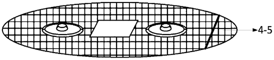
- Figure 6 is a schematic plan view of the patch
- Figure 7 is a three-dimensional schematic diagram of the patch
- Figure 8 is a schematic diagram of the structure of the electrode assembly
- Figure 9 is a schematic diagram of the plane layout of the surface of the flexible bottom plate in another embodiment (four electrodes);
- Figure 10 is a schematic plan view of a patch in another embodiment (four electrodes);
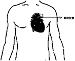
- Figure 11 is a schematic diagram of the attachment position of the chest non-invasive blood pressure detection probe on the human body
- FIG. 12 is a schematic diagram of the unit structure of a chest non-invasive blood pressure detection device based on pulse wave transit time
- Fig. 13 is a schematic diagram of the arrangement of the signal processing system matched with the probe on the base board.
- the reference signs in the figure are: housing 1, electrode female button 2-1, photoelectric sensor module 2-2, acceleration sensor 2-3, flexible base plate 2-4, LED array 3-1, photoelectric receiving tube 3-2, Patch 4, electrode pin 4-1, gel layer 4-2, first electrode 4-3, second electrode 4-4, reference electrode 4-5, spring conductive wire 4-6, fixed telescopic rod 4- 7.
- the purpose of the present invention is to provide a chest non-invasive blood pressure detection probe and its device based on pulse wave transit time, so as to avoid the restriction of lead wires, and have small size, high comfort, high measurement accuracy, and high medical value. While having advantages such as broad market application prospects, it also improves comfort and portability.
- the chest non-invasive blood pressure detection probe based on pulse wave transit time provided by the present invention includes: a housing 1, a patch 4 and an elastic device.
- the bottom of the housing 1 is provided with a flexible bottom plate 2-4, and the surface of the flexible bottom plate 2-4 is provided with a plurality of electrode female buttons 2-1, a photoelectric sensor module 2-2 and an acceleration sensor 2-3. .
- the electrode female button 2-1 and the acceleration sensor 2-3 are arranged in a fit on the surface of the flexible bottom plate 2-4.
- the photoelectric sensor module 2-2 is fixed on the elastic device.
- the elastic device includes: a fixed telescopic rod 4-7 and a spring conductive wire 4-6.
- Two fixed telescopic rods 4-7 are fixed at the bottom of the photoelectric sensor module 2-2. Slot holes are opened on the flexible bottom plate 2-4. The two fixed telescopic rods 4-7 are inserted into the slots to form a movable pair capable of telescopic adjustment.
- the bottom of the photoelectric sensor module 2-2 is connected to one end of the spring conductive wire 4-6, and the other end of the spring conductive wire 4-6 is supported on the flexible bottom plate 2-4.
- the surface of the photoelectric sensor module 2-2 is higher than the surface of the flexible bottom plate 2-4 without external pressure.
- the patch 4 is provided with a number of electrode assemblies.
- Each of the electrode assemblies includes an electrode sheet and an electrode pin 4-1.
- the outer contour of the patch 4 is the same as the surface of the flexible bottom plate 2-4, and the middle of the patch 4 is provided with a hollow area.
- the photoelectric sensor module 2-2 is placed in the hollow area, and the photoelectric sensor module 2-2 passes through the fixed telescopic rod 4-7 and the flexible bottom plate 2-4 inserted into the slot. connection.
- the electrode male buckles 4-1 of all electrode assemblies are fixed and embedded on the surface of the patch 4, and the positions of the electrode male buckles 4-1 correspond to the positions of the electrode female buckles 2-1 one-to-one.
- the electrode male buckle 4-1 and the electrode female buckle 2-1 are clamped and fixed in pairs.
- An electrode sheet is attached to the surface of each electrode male button 4-1.
- the electrode assemblies are arranged in pairs, and the electrode assemblies include two arrangements of double electrodes and four electrodes.
- the electrode components of each pair are symmetrically arranged with the photoelectric sensor module 2-2 as the center.
- the patch 4 is also provided with a reference electrode 4-5.
- the material of the electrode sheet is Ag/AgCl, metal or fabric electrode.
- the surface of the electrode sheet is coated with a gel layer 4-2.
- the photoelectric sensor module 2-2 includes a photoelectric receiving tube 3-2 and an LED array 3-1.
- the photoelectric receiving tube 3-2 is used to receive the light beam emitted by the LED array 3-1 and reflected by the human skin.
- the number of the photoelectric receiving tube 3-2 and the LED array 3-1 is one or more.
- a cavity for accommodating a detection circuit is provided between the housing 1 and the flexible bottom plate 2-4.
- the material of the housing 1 and/or the flexible bottom plate 2-4 is polydimethylsiloxane.
- the invention also provides a chest non-invasive blood pressure detection device based on pulse wave transit time.
- the detection device includes: an electrocardiogram/cardiac impedance signal detection unit, a pulse signal detection unit, an accelerated plethysmography signal detection unit, a main control/Bluetooth unit, a power management unit and a storage unit.
- the electrocardiogram/cardiac impedance signal detection unit includes: an electrocardiogram signal acquisition front end and a pair of electrode assemblies in the above-mentioned pulse wave transit time-based chest non-invasive blood pressure detection probe.
- the electrode assembly is electrically connected with the ECG signal collection front end.
- the electrode sheet located on the electrode assembly is used for picking up ECG signals and ICG signals on the surface of the human body.
- the ECG signal acquisition front end processes and converts the ECG signal and the ICG signal.
- the pulse signal detection unit includes: a pulse collection front end and the photoelectric sensor module 2-2 in the chest non-invasive blood pressure detection probe based on pulse wave transit time.
- the photoelectric sensor module 2-2 is electrically connected to the pulse collection front end.
- the photoelectric sensor module 2-2 picks up human pulse and blood flow volume signals based on the photovolumetric method, and the pulse acquisition front end processes and converts the human pulse and blood flow volume signals.
- the acceleration plethysmography signal detection unit includes: an analog front end and the aforementioned acceleration sensor 2-3 of the chest non-invasive blood pressure detection probe based on pulse wave transit time.
- the acceleration sensor 2-3 is electrically connected to the analog front end.
- the acceleration sensor 2-3 is used to collect the APG signal of human arterial acceleration plethysmography.
- the analog front end processes and converts the APG signal of the human arterial acceleration plethysmography.
- the main control/Bluetooth unit includes: a main control chip.
- the main control chip includes a Bluetooth BLE low power consumption protocol stack.
- the main control chip is electrically connected with the electrocardiogram/cardiac impedance signal detection unit, the pulse signal detection unit, the accelerated plethysmography signal detection unit, the power management unit and the storage unit, respectively.
- the main control chip is used to control each signal detection unit to collect signal data and perform signal processing on the collected signals to obtain blood pressure detection results.
- the signal processing includes: signal analysis, feature extraction and blood pressure calculation.
- the power management unit is used to provide electrical energy for each power consumption unit in the detection device.
- the storage unit is used to store local data.
- the ECG signal collection front end, the pulse collection front end, the analog front end, the main control/Bluetooth unit, the power management unit and the storage unit are all integrated in the detection probe.
- one electrode assembly serves as an RA electrode, and the other electrode assembly serves as an LA electrode.
- the paired electrode assemblies are used to detect cardiac impedance signals, one electrode assembly serves as a detection electrode and the other electrode serves as an excitation electrode.
- the power management unit includes a lithium battery module, a voltage stabilizing circuit and a USB interface.
- the USB interface is used for external power supply.
- the lithium battery module is used for internal power supply.
- the voltage stabilizing circuit is used to convert the voltage and maintain a stable output of the voltage.
- a chest non-invasive blood pressure detection probe based on pulse wave transit time includes a probe body part and a patch 4.
- the electrode sheet of the present invention is set on the patch 4, and then mounted on the probe body part in the form of a male and female buckle for use.
- the patch 4 can be directly removed and replaced. On the new patch.
- the probe body part includes a housing 1 and a flexible bottom plate 2-4.
- the housing 1 is in the shape of a semi-elliptical shell.
- the flexible bottom plate 2-4 is arranged at the bottom of the housing 1 to close the lower open part of the housing 1.
- the internal base board for carrying the detection circuit, the housing 1 and the flexible bottom board 2-4 need to be made of flexible materials.
- each detection element has its own installation form, which will be described in detail below.
- the surface of the flexible base plate 2-4 is provided with a plurality of electrode female buttons 2-1, a photoelectric sensor module 2-2 and an acceleration sensor 2-3.
- two electrode female buttons 2-1 are provided, and they are symmetrically arranged on both sides of the photoelectric sensor module 2-2, so they are in the form of double electrodes.
- the acceleration sensor 2-3 is arranged above the photoelectric sensor module 2-2.
- the electrode female button 2-1 and the acceleration sensor 2-3 are attached and arranged on the surface of the flexible base plate 2-4.
- the photoelectric sensor module 2-2 is fixed on the elastic device.
- the elastic device includes 2 fixed telescopic rods 4-7 and 1 spring conductive wire 4-6.
- Two fixed telescopic rods 4-7 are vertically fixed at the bottom of the photoelectric sensor module 2-2, the two fixed telescopic rods 4-7 are inserted into the slots opened on the flexible base plate 2-4, and the two fixed telescopic rods 4-7 and The slot holes constitute a moving pair that can be adjusted up and down, and the photoelectric sensor module 2-2 is always kept parallel to the surface of the flexible bottom plate 2-4 during the up and down movement.
- the spring conductive wire 4-6 is a spring-like conductive signal wire with elasticity.
- the bottom of the photoelectric sensor module 2-2 is connected to one end of the spring conductive wire 4-6, and the other end of the spring conductive wire 4-6 is supported on the flexible bottom plate 2- 4 on.
- the photoelectric sensor module 2-2 protrudes from the surface of the flexible bottom plate 2-4 through the support of the spring conductive wire 4-6 under the condition of not being subjected to external pressure.
- the spring conductive wire 4-6 moves to the side of the flexible base plate 2-4, and the photoelectric sensor module 2-2 is attached to the skin. Therefore, the elastic device can ensure that the photoelectric sensor module 2-2 is in close contact with the skin when in use, thereby improving signal quality.
- the bottom of the spring conductive wire 4-6 can extend into the bottom of the flexible base plate 2-4, and connect with the detection circuit to transmit the original data collected by the photoelectric receiving tube PD.
- the signal line of the acceleration sensor 2-3 also extends under the flexible base plate 2-4 to connect to the detection circuit.
- the photoelectric sensor module 2-2 collects human pulse and blood flow volume signals, and the photoelectric sensor module 2-2 can perform data collection and processing based on the photovolume method.
- the photoelectric sensor module 2-2 includes one or more photoreceiving tubes PD3-2 and one or more LED arrays 3-1, and the photoreceiving tubes 3-2 are used to receive the LED array 3-1 after being reflected by the skin. beam.
- the pulse signal PPG is collected by the photoelectric sensor module 2-2, and the light beam of a certain wavelength emitted by the LED array 3-1 passes through the skin of the chest cavity, and is reflected by the skin and received by the photoelectric receiving tube 3-2, which converts the photoelectric signal into an electrical signal for output. Obtain the fluctuation of arterial blood.
- the LED array 3-1 and the photoreceiving tube 3-2 there are many ways to arrange the LED array 3-1 and the photoreceiving tube 3-2. Parts a to c in Fig. 5 list three of them, but they can be selected according to actual applications.
- the LED array preferably includes LEDs with three wavelengths of 880 nm, 660 nm, and 940 nm, and the specific wavelengths of the LEDs can also be adjusted as required.
- the above-mentioned probe body part is used to integrate electronic components required for detection, and serves as a mounting bracket for the patch 4.
- the patch 4 is provided with two electrode assemblies, and each electrode assembly includes an electrode sheet and an electrode pin 4-1.
- the outer contour of the patch 4 is the same as the surface of the flexible base plate 2-4, and a hollow area is opened in the middle.
- the photoelectric sensor module 2-2 can pass through the hollow area Extend the surface to facilitate contact with the skin.
- the electrode male buttons 4-1 of all the electrode assemblies are inlaid and fixed on the surface of the patch 4, and their positions correspond to the electrode female buttons 2-1 on the surface of the flexible bottom plate 2-4 one by one, that is, when the patch 4 is attached to the flexible bottom plate 2
- the electrode male buckle 4-1 and the electrode female buckle 2-1 can be fixed in pairs.
- the fixing of the male and female buckles is detachable and can be removed and replaced at any time.
- the surface of each electrode pin 4-1 is attached with an electrode sheet, and the surface of the electrode sheet is coated with a gel layer 4-2 to ensure the stability of the detection source signal and the reliability of contact.
- the electrode female buckle 2-1 and the electrode male buckle 4-1 have matching contacts for signal transmission, and the electrode female buckle 2-1 is directly connected to the detection circuit inward.
- the signal is collected by the electrode sheet, and then enters the detection circuit through the electrode male and female buckle for subsequent signal processing.
- a reference electrode 4-5 is also provided at one side edge of the patch 4.
- the reference electrode 4-5 can be directly attached to the patch, of course, it can also be in the form of a male and female buckle.
- the material of each electrode sheet can be Ag/AgCl, metal or fabric electrode.
- the electrode assemblies are arranged in pairs, two as a pair, and there are two types of double electrodes and four electrodes.
- a double electrode form is adopted.
- the two electrodes can be multiplexed to detect ECG and cardiac impedance signals.
- the first electrode 4-3 is the RA electrode
- the second electrode 4-4 is the LA electrode.
- RA and LA can also be used for reference
- the electrodes 4-5 reduce common mode interference, thereby detecting the electrical signal ECG of the human heart movement.
- RA and LA electrodes can be reused for ICG detection of cardiac impedance signals: when detecting cardiac impedance signals, the first electrode 4-3 is the detection electrode, and the second electrode 4-4 is the excitation electrode. The two cooperate to extract the impedance of the aortic blood flow Change signal.
- a four-electrode form can also be used, which are symmetrically distributed on both sides of the photoelectric sensor module 2-2.
- the schematic plan view of the surface of the flexible bottom plate is shown in FIG. 9, and the plan view of the patch also needs to be adaptively adjusted as shown in FIG. 10.
- there are two pairs of electrode assemblies namely, two first electrodes 4-3 and two second electrodes 4-4.
- one first electrode 4-3 is taken as the RA electrode
- one second electrode 4-4 is taken as the LA electrode.
- the four electrodes are multiplexed to detect the cardiac impedance signal ICG.
- the two first electrodes 4-3 are used as detection electrodes
- the two second electrodes 4-4 are used as excitation electrodes.
- the reference electrode 4-5 can also be used to reduce common mode interference.
- the housing 1 is made of a flexible skin-friendly material to facilitate the overall deformation of the probe and better fit the skin.
- Both the shell 1 and the flexible bottom plate 2-4 can be made of polydimethylsiloxane (PDMS).
- the surface of the patch 4 can be made of a sticky material or coated to form a sticking layer, so that the detection probe and device provided by the present invention can be attached to the human skin surface at the chest position. Realize the wearable function, get rid of the shackles of the traditional blood pressure measurement airbag on the human body, and improve the comfort and portability.
- the detection probe is used for continuous dynamic real-time acquisition of portable human aortic blood pressure, free of lead wires, small size, high comfort, high measurement accuracy, high medical value and broad market application prospects.
- the function of the above-mentioned non-invasive chest blood pressure detection probe based on pulse wave transit time is to obtain blood pressure-related detection signals, but its specific data processing needs to be implemented with corresponding circuits.
- the present invention proposes a chest non-invasive blood pressure detection device based on pulse wave transit time based on the detection probe.
- the detection device also includes a signal processing system matched with the probe.
- the probe and the signal processing system as a whole have the functions of signal acquisition, transmission and processing. The whole is divided into ECG/cardiac impedance signal detection unit, pulse signal detection unit, accelerated plethysmography signal detection unit, main control/Bluetooth unit, power management Unit and storage unit.
- the ECG/cardiac impedance signal detection unit includes the front end of the ECG signal acquisition and the electrode assembly on the patch 4.
- the electrode sheet located on the electrode assembly is used to pick up the ECG and ICG signals of the human body surface. After acquiring the ECG and ICG signals, the acquisition front end processes and converts the signals.
- the pulse signal detection unit includes a photoelectric sensor module 2-2 and a pulse collection front end. The photoelectric sensor module 2-2 picks up human pulse and blood flow volume signals based on the photovolumetric method, and the pulse collection front end processes and converts the signals.
- the acceleration plethysmography signal detection unit includes an acceleration sensor 2-3 and an analog front end.
- the acceleration sensor 2-3 is used to collect human arterial acceleration plethysmography APG signals, and the analog front end processes and converts the signals.
- the main control/Bluetooth unit includes a main control chip, and the main control chip includes a Bluetooth BLE low-power protocol stack.
- the main control chip is used to control the ECG/cardiac impedance signal detection unit, pulse signal detection unit, acceleration plethysmography signal detection unit, etc.
- the signal data of the signal detection unit is collected, and the signal is received, stored, analyzed, feature extraction, and blood pressure calculation, and then the blood pressure detection result is sent to the terminal through the Bluetooth protocol stack.
- the power management unit is used to supply power to the power consumption unit.
- the power management unit can include a lithium battery module, a voltage regulator circuit and a USB interface.
- the USB is used for external power supply and also used to charge the lithium battery module.
- the voltage regulator circuit is used to convert the voltage and maintain a stable output.
- the storage unit is used to store local data, and a MicroSD card can be used.
- the use process of the chest non-invasive blood pressure detection device is as follows: the probe body part and the patch part are assembled through the electrode male and female buckle, the system is attached to the human chest aorta outlet ( Figure 11), the photoelectric sensor module 2-2 is in the elastic force Under the action, it sticks to the skin and starts to detect the human aortic blood pressure. After starting the detection, the main control unit controls each signal detection unit to start collecting signals.
- the ECG/cardiac impedance signal detection unit picks up ECG signals through RA, LA and reference electrodes 4-5, and picks up ICG signals through excitation electrodes and detection electrodes, ECG/
- the ICG signal is collected, converted, amplified and processed by the ECG/cardiac impedance signal analog front end and then sent to the main control unit.
- the pulse signal detection unit collects the human aortic PPG signal through the photoelectric sensor module 2-2, and sends it to the main control chip in the main control/Bluetooth unit after being amplified by the pulse signal analog front end and converted.
- the main control chip performs waveform processing and feature extraction on the aggregated signals, calculates blood pressure according to the blood pressure calculation model, and sends the results to the terminal (mobile phone/PC side) via Bluetooth.
- Electrode reusable cardiac impedance signal ICG detection high-frequency low-amplitude constant current is input from the excitation electrode, the cardiac cycle activity causes the cyclic change of the chest blood flow and then the cyclic resistance of the chest cavity, the detection electrode detects the voltage signal induced by the aortic blood flow, The impedance change signal ICG of the aortic blood flow is extracted from the voltage signal through the switch demodulator.
- the accelerating plethysmography signal APG is acquired by the high-sensitivity acceleration sensor 2-3, which can reliably capture the changes in the displacement of the arterial wall to the skin surface caused by the retraction of the heart.
- the pulse signal PPG is collected by the photoelectric sensor module 2-2, and the light beam of a certain wavelength emitted by the LED array 3-1 passes through the skin of the chest cavity, and is reflected by the skin and received by the photoelectric receiving tube 3-2, which converts the photoelectric signal into an electrical signal for output. Obtain the fluctuation of arterial blood.
- the analysis and processing program in the main control unit can be set as needed.
- one of the methods for calculating blood pressure in the main control unit is given below.
- the specific calculation process is as follows:
- the main control unit After the main control unit obtains the detection data of the individual to be tested, it can perform feature extraction on the original waveform signal.
- the detection data includes ECG signal, PPG signal, ICG signal and APG signal.
- Pulse wave morphology parameters C include AIx, SIx, RT, DT, K, PA, PHH, Pmax, Pmin and Ppeak, etc.
- the parameters ⁇ , ⁇ , ⁇ , and ⁇ in the above blood pressure model are all weights, and the specific values can be calibrated and fitted in advance using calibration data containing accurate blood pressure values to obtain corresponding fitting parameters.
- the blood pressure model is improved on the traditional blood pressure model based on pulse wave transit time. Taking into account the pre-ejection period and other factors that affect blood pressure changes, the blood pressure model is carried out by adding parameters such as heart rate, pulse wave morphology parameters, and skin conductance. The correction can ensure that a more accurate blood pressure value is obtained in a longer calibration interval. Using this method, systolic blood pressure SBP and diastolic blood pressure DBP can be obtained through calibration. In order to prove the effect of the method of the present invention, multiple sets of data of a single sample are selected for error analysis and compared with two classic models. The error analysis of the mean and variance of systolic and diastolic blood pressure is shown in Table 1 below, which shows that the present invention The accuracy of blood pressure calculation methods has been significantly improved.
- the detection probe of the present invention is mainly a front-end data acquisition component, and its purpose is to provide a probe structure capable of acquiring different blood pressure related parameters.
- the specific back-end processing circuits, modules, units, etc. can be adjusted according to actual needs, and the blood pressure calculation algorithm can also use the corresponding model in the prior art, which is not limited.
- the chest non-invasive blood pressure detection probe of the present invention is used as a wearable signal acquisition system, which can be attached to the human skin surface at the chest position, and adopts a split probe body part and patch, which are attached and installed in the form of male and female buckles. It is used on the probe body. When it needs to be replaced, the patch can be directly removed and replaced with a new patch, which is convenient to use.
- the present invention takes into account that the pulse wave transit time PTT in the traditional detection method ignores the time parameter of the pre-ejection period. Therefore, the measurement position is fixed at the exit of the chest aorta, and the ECG signal and the aortic accelerometer signal are used. APG obtains the cardiac ejection time PEP, and removes the PEP influence from PTT, and obtains a more accurate pulse wave transit time PTT', making the detected conduction time closer to the actual conduction time, ensuring accurate aortic blood pressure .
- the present invention takes into account the defect that the accuracy of traditional non-invasive blood pressure detection is not ideal, and improves the blood pressure model by adding heart rate HR, pulse wave morphology parameter C and skin conductance ⁇ , so that the model fitting result is more accurate.
- the present invention uses the principle of non-invasive and continuous blood pressure measurement by PTT, integrates the signal acquisition system into the chest wearable device, and can synchronously obtain chest I-lead electrocardiogram, impedance cardiogram, aortic plethysmography pulse wave, and aorta during detection. Accelerogram.
- the measurement device has a simple structure and simple operation mode, which frees itself from the shackles of traditional blood pressure measurement airbags on the human body, and improves comfort and portability. This probe is used for continuous dynamic real-time acquisition of human aortic blood pressure in a portable way, free of lead wires, small size, high comfort, high measurement accuracy, and has high medical value and broad market application prospects.
Landscapes
- Health & Medical Sciences (AREA)
- Life Sciences & Earth Sciences (AREA)
- Engineering & Computer Science (AREA)
- Veterinary Medicine (AREA)
- Pathology (AREA)
- Biophysics (AREA)
- Biomedical Technology (AREA)
- Heart & Thoracic Surgery (AREA)
- Medical Informatics (AREA)
- Molecular Biology (AREA)
- Surgery (AREA)
- Animal Behavior & Ethology (AREA)
- General Health & Medical Sciences (AREA)
- Public Health (AREA)
- Physics & Mathematics (AREA)
- Cardiology (AREA)
- Physiology (AREA)
- Vascular Medicine (AREA)
- Dentistry (AREA)
- Oral & Maxillofacial Surgery (AREA)
- Hematology (AREA)
- Dispersion Chemistry (AREA)
- Chemical & Material Sciences (AREA)
- Pulmonology (AREA)
- Artificial Intelligence (AREA)
- Computer Vision & Pattern Recognition (AREA)
- Psychiatry (AREA)
- Signal Processing (AREA)
- Measuring Pulse, Heart Rate, Blood Pressure Or Blood Flow (AREA)
- Computer Networks & Wireless Communication (AREA)
Abstract
一种基于脉搏波传导时间的胸口无创血压检测探头及其装置。检测探头可以贴附在胸口位置的人体皮肤表面,而且采用分体式的探头本体部分和贴片(4),通过公母扣的形式贴合安装于探头本体部分上使用,当需要更换时可直接将贴片(4)取下重新换上新的贴片(4),方便使用。检测探头用于便携式人体主动脉血压的连续动态实时采集,免除了导联线的束缚,体积小、舒适性高、测量精度高。检测装置可将信号采集系统集成于上述检测探头中,使得测量设备结构简单且操作方式简便,摆脱了传统血压测量气囊对人体的束缚,提高了舒适性和便携性。
Description
本申请要求于2019年07月03日提交中国专利局、申请号为201910595774.6、发明名称为“基于脉搏波传导时间的胸口无创血压检测探头及其装置”的中国专利申请的优先权,其全部内容通过引用结合在本申请中。
本发明属于无创血压监测设备领域,具体涉及一种基于脉搏波传导时间的胸口无创血压检测探头及其装置。
血压是反映人体心血管状况的重要生理参数之一。人体血压具有波动性。连续无创血压测量能够检测逐拍动脉血压,有助于心血管疾病的预防、诊断、治疗和控制。目前的无创血压检测技术大体分为间歇测量和连续测量。间歇测量法包括听诊法和示波法,具有准确度高的特点,但是对操作者要求高且只能得到间歇血压值。连续测量法包括动脉张力法、容积补偿法及脉搏波速法等。动脉张力法和容积补偿法虽然较为成熟,但其对传感器位置敏感,且因长期测量导致静脉充血,使用户产生不适感。而脉搏波速相关方法因具备无干扰、可动态测量等优点成为近年来的研究热点。
传统的基于脉搏波传导时间的血压检测方法,存在只能测量单一血压指标、需频繁校准且准确度欠佳的问题。存在该问题的原因之一是,传统的方法忽视了血管收缩舒张能力及射血前期PEP对血压波动的影响,仅靠PTT单一参数对血压进行估计,无法长期追踪动态血压。除此之外,传统的方法采集部位通常位于腕部、手指、四肢等,这样将导致测量的脉 搏波传导时间不仅包括了与血压呈线性关系的主动脉脉搏波传导时间,还包括了心脏射血期、桡动脉或颈总动脉的传导时间及局部毛细血管末梢的传导时间,导致检测的血压参数与实际的血压参数存在误差。除此之外,传统的检测装置体积较大,使用较复杂,传感器刚度大且胶状电极易导致皮肤过敏,给用户造成了不便。
因此,有待于提供一种穿戴舒适、稳定性强、能进一步提高血压检测的准确性的胸口无创血压检测探头。而由于需要在可穿戴式的探头上集成不同的检测元件,因此对于探头的结构设计提出了新的要求。
发明内容
本发明的目的在于为解决现有技术中存在的问题,提供了一种基于脉搏波传导时间的胸口无创血压检测探头及其装置。
为实现上述目的,本发明提供了如下方案:
一种基于脉搏波传导时间的胸口无创血压检测探头,包括:外壳、贴片和弹性装置;
其中,所述外壳底部设有柔性底板,所述柔性底板的表面设有若干个电极母扣、一个光电传感器模组和一个加速度传感器;
所述电极母扣和所述加速度传感器贴合布置于所述柔性底板的表面;所述光电传感器模组固定在所述弹性装置上;
所述弹性装置包括:固定伸缩杆和弹簧导电线;
所述光电传感器模组底部固定有两条固定伸缩杆;所述柔性底板上开设有槽孔;两条所述固定伸缩杆插入所述槽孔中,以构成能伸缩调节的移动副;所述光电传感器模组的底部连接所述弹簧导电线的一端,所述弹簧 导电线的另一端支顶于所述柔性底板上;所述光电传感器模组的表面在不受外部压力的状态下高于所述柔性底板的表面;
所述贴片中设有若干电极组件;每个所述电极组件包括电极片和电极公扣;
所述贴片的外轮廓与所述柔性底板的表面相同,且所述贴片的中部开设有一个镂空区域;所述光电传感器模组置于所述镂空区域,且所述光电传感器模组通过插入所述槽孔中的所述固定伸缩杆与所述柔性底板连接;所有电极组件的所述电极公扣均固定镶嵌于所述贴片的表面,且所述电极公扣的位置与所述电极母扣的位置一一对应,所述电极公扣和所述电极母扣成对卡合固定;每个所述电极公扣的表面均贴有电极片。
优选的,所述电极组件成对设置,所述电极组件包括双电极和四电极两种设置形式;每对所述电极组件以所述光电传感器模组为中心对称设置。
优选的,所述贴片上还设有参考电极。
优选的,所述电极片材质为Ag/AgCl、金属或织物电极;所述电极片的表面涂敷有凝胶层。
优选的,所述光电传感器模组包括光电接收管和LED阵列;所述光电接收管用于接收所述LED阵列发出的经过人体皮肤反射后的光束;
所述光电接收管和所述LED阵列的个数为一个或多个。
优选的,所述外壳与所述柔性底板之间设有用于容纳检测电路的空腔。
优选的,所述外壳和/或所述柔性底板的材料为聚二甲基硅氧烷。
一种基于脉搏波传导时间的胸口无创血压检测装置,包括:心电/心阻抗信号检测单元、脉搏信号检测单元、加速体积描记信号检测单元、主控/蓝牙单元、电源管理单元和存储单元;
所述心电/心阻抗信号检测单元包括:心电信号采集前端和上述基于脉搏波传导时间的胸口无创血压检测探头中的成对设置的电极组件;所述电极组件与所述心电信号采集前端电连接;
位于所述电极组件上的电极片用于拾取人体体表的ECG信号和ICG信号;心电信号采集前端对所述ECG信号和ICG信号进行处理转换;
所述脉搏信号检测单元包括:脉搏采集前端和上述基于脉搏波传导时间的胸口无创血压检测探头中的光电传感器模组;所述光电传感器模组与所述脉搏采集前端电连接;
所述光电传感器模组基于光电容积法拾取人体脉搏及血流容积信号,脉搏采集前端对所述人体脉搏及血流容积信号进行处理转换;
所述加速度体积描记信号检测单元包括:模拟前端和上述基于脉搏波传导时间的胸口无创血压检测探头的加速度传感器;所述加速度传感器和所述模拟前端电连接;
所述加速度传感器用于采集人体动脉加速体积描记APG信号;所述模拟前端对所述人体动脉加速体积描记APG信号进行处理转换;
所述主控/蓝牙单元包括:主控芯片;所述主控芯片包含蓝牙BLE低功耗协议栈;所述主控芯片分别与所述心电/心阻抗信号检测单元、所述脉搏信号检测单元、所述加速体积描记信号检测单元、所述电源管理单元和所述存储单元电连接;
所述主控芯片用于控制各信号检测单元采集信号数据,并对所采集的信号进行信号处理,得到血压检测结果;所述信号处理包括:信号分析、特征提取和血压计算;
采用所述蓝牙BLE低功耗协议栈将所述血压检测结果发送给终端;
所述电源管理单元用于为所述检测装置中的各耗电单元提供电能;
所述存储单元用于存储本地数据;
所述心电信号采集前端、所述脉搏采集前端、所述模拟前端、所述主控/蓝牙单元、所述电源管理单元和所述存储单元均集成于上述检测探头中。
优选的,当所述成对设置的电极组件用于检测心电信号时,一个电极组件作为RA电极,另一个电极组件作为LA电极;当所述成对设置的电极组件用于检测心阻抗信号时,一个电极组件作为检测电极,另一个电极作为激励电极。
优选的,所述电源管理单元包含锂电池模组、稳压电路和USB接口;
所述USB接口用于外接供电电源;所述锂电池模组用于内部供电;所述稳压电路用于对电压进行转换并保持电压的稳定输出。
根据本发明提供的具体实施例,本发明公开了以下技术效果:本发明提供的基于脉搏波传导时间的胸口无创血压检测探头,可以贴附在胸口位置的人体皮肤表面,而且采用分体式的探头本体部分和贴片,通过公母扣的形式贴合安装于探头本体部分上使用,当需要更换时可直接将贴片取下重新换上新的贴片,方便使用。并且,该检测探头用于便携式人体主动脉血压的连续动态实时采集,免除了导联线的束缚,体积小、舒适性高、测 量精度高,具有较高的医用价值和广阔的市场应用前景。
此外本发明提供的基于脉搏波传导时间的胸口无创血压检测装置,可将信号采集系统(心电信号采集前端、脉搏采集前端、模拟前端和主控/蓝牙单元)集成于上述检测探头中,使得测量设备结构简单且操作方式简便,摆脱了传统血压测量气囊对人体的束缚,提高了舒适性和便携性。
说明书附图
为了更清楚地说明本发明实施例或现有技术中的技术方案,下面将对实施例中所需要使用的附图作简单地介绍,显而易见地,下面描述中的附图仅仅是本发明的一些实施例,对于本领域普通技术人员来讲,在不付出创造性劳动性的前提下,还可以根据这些附图获得其他的附图。
图1为基于脉搏波传导时间的胸口无创血压检测探头的整体结构示意图;
图2为探头本体部分立体结构示意图;
图3为探头本体部分的侧视图;
图4为探头本体部分柔性底板表面的平面布置示意图(双电极);
图5为光电传感器模组的三种布置形式示意图;
图6为贴片的平面示意图;
图7为贴片的立体示意图;
图8为电极组件的结构示意图;
图9为另一实施例中柔性底板表面的平面布置示意图(四电极);
图10为另一实施例中贴片的平面示意图(四电极);
图11为胸口无创血压检测探头在人体上的贴附位置示意图;
图12为基于脉搏波传导时间的胸口无创血压检测装置的单元结构示意图;
图13为与探头配合的信号处理系统在基底板上的布置示意图。
图中附图标记为:外壳1,电极母扣2-1,光电传感器模组2-2,加速度传感器2-3,柔性底板2-4,LED阵列3-1,光电接收管3-2,贴片4,电极公扣4-1,凝胶层4-2,第一电极4-3,第二电极4-4,参考电极4-5,弹簧导电线4-6,固定伸缩杆4-7。
下面将结合本发明实施例中的附图,对本发明实施例中的技术方案进行清楚、完整地描述,显然,所描述的实施例仅仅是本发明一部分实施例,而不是全部的实施例。基于本发明中的实施例,本领域普通技术人员在没有做出创造性劳动前提下所获得的所有其他实施例,都属于本发明保护的范围。
本发明的目的是提供一种基于脉搏波传导时间的胸口无创血压检测探头及其装置,以在免除导联线的束缚,具有体积小、舒适性高、测量精度高、较高的医用价值、广阔的市场应用前景等优点的同时,提高了舒适性和便携性。
为使本发明的上述目的、特征和优点能够更加明显易懂,下面结合附图和具体实施方式对本发明作进一步详细的说明。本发明中各个实施方式的技术特征在没有相互冲突的前提下,均可进行相应组合。
实施例1
如图1~10所示,本发明提供的基于脉搏波传导时间的胸口无创血压 检测探头,包括:外壳1、贴片4和弹性装置。
其中,所述外壳1底部设有柔性底板2-4,所述柔性底板2-4的表面设有若干个电极母扣2-1、一个光电传感器模组2-2和一个加速度传感器2-3。
所述电极母扣2-1和所述加速度传感器2-3贴合布置于所述柔性底板2-4的表面。所述光电传感器模组2-2固定在所述弹性装置上。
所述弹性装置包括:固定伸缩杆4-7和弹簧导电线4-6。
所述光电传感器模组2-2底部固定有两条固定伸缩杆4-7。所述柔性底板2-4上开设有槽孔。两条所述固定伸缩杆4-7插入所述槽孔中,以构成能伸缩调节的移动副。所述光电传感器模组2-2的底部连接所述弹簧导电线4-6的一端,所述弹簧导电线4-6的另一端支顶于所述柔性底板2-4上。所述光电传感器模组2-2的表面在不受外部压力的状态下高于所述柔性底板2-4的表面。
所述贴片4中设有若干电极组件。每个所述电极组件包括电极片和电极公扣4-1。
所述贴片4的外轮廓与所述柔性底板2-4的表面相同,且所述贴片4的中部开设有一个镂空区域。所述光电传感器模组2-2置于所述镂空区域,且所述光电传感器模组2-2通过插入所述槽孔中的所述固定伸缩杆4-7与所述柔性底板2-4连接。所有电极组件的所述电极公扣4-1均固定镶嵌于所述贴片4的表面,且所述电极公扣4-1的位置与所述电极母扣2-1的位置一一对应,所述电极公扣4-1和所述电极母扣2-1成对卡合固定。每个所述电极公扣4-1的表面均贴有电极片。
优选的,所述电极组件成对设置,所述电极组件包括双电极和四电极两种设置形式。每对所述电极组件以所述光电传感器模组2-2为中心对称设置。
优选的,所述贴片4上还设有参考电极4-5。
优选的,所述电极片材质为Ag/AgCl、金属或织物电极。所述电极片的表面涂敷有凝胶层4-2。
优选的,所述光电传感器模组2-2包括光电接收管3-2和LED阵列3-1。所述光电接收管3-2用于接收所述LED阵列3-1发出的经过人体皮肤反射后的光束。
所述光电接收管3-2和所述LED阵列3-1的个数为一个或多个。
优选的,所述外壳1与所述柔性底板2-4之间设有用于容纳检测电路的空腔。
优选的,所述外壳1和/或所述柔性底板2-4的材料为聚二甲基硅氧烷。
本发明还提供了一种基于脉搏波传导时间的胸口无创血压检测装置。该检测装置包括:心电/心阻抗信号检测单元、脉搏信号检测单元、加速体积描记信号检测单元、主控/蓝牙单元、电源管理单元和存储单元。
所述心电/心阻抗信号检测单元包括:心电信号采集前端和上述基于脉搏波传导时间的胸口无创血压检测探头中的成对设置的电极组件。所述电极组件与所述心电信号采集前端电连接。
位于所述电极组件上的电极片用于拾取人体体表的ECG信号和ICG信号。心电信号采集前端对所述ECG信号和ICG信号进行处理转换。
所述脉搏信号检测单元包括:脉搏采集前端和上述基于脉搏波传导时间的胸口无创血压检测探头中的光电传感器模组2-2。所述光电传感器模组2-2与所述脉搏采集前端电连接。
所述光电传感器模组2-2基于光电容积法拾取人体脉搏及血流容积信号,脉搏采集前端对所述人体脉搏及血流容积信号进行处理转换。
所述加速度体积描记信号检测单元包括:模拟前端和上述基于脉搏波传导时间的胸口无创血压检测探头的加速度传感器2-3。所述加速度传感器2-3和所述模拟前端电连接。
所述加速度传感器2-3用于采集人体动脉加速体积描记APG信号。所述模拟前端对所述人体动脉加速体积描记APG信号进行处理转换。所述主控/蓝牙单元包括:主控芯片。所述主控芯片包含蓝牙BLE低功耗协议栈。所述主控芯片分别与所述心电/心阻抗信号检测单元、所述脉搏信号检测单元、所述加速体积描记信号检测单元、所述电源管理单元和所述存储单元电连接。
所述主控芯片用于控制各信号检测单元采集信号数据,并对所采集的信号进行信号处理,得到血压检测结果。所述信号处理包括:信号分析、特征提取和血压计算。
采用所述蓝牙BLE低功耗协议栈将所述血压检测结果发送给终端。
所述电源管理单元用于为所述检测装置中的各耗电单元提供电能。
所述存储单元用于存储本地数据。
所述心电信号采集前端、所述脉搏采集前端、所述模拟前端、所述主控/蓝牙单元、所述电源管理单元和所述存储单元均集成于上述检测探头 中。
优选的,当所述成对设置的电极组件用于检测心电信号时,一个电极组件作为RA电极,另一个电极组件作为LA电极。当所述成对设置的电极组件用于检测心阻抗信号时,一个电极组件作为检测电极,另一个电极作为激励电极。
优选的,所述电源管理单元包含锂电池模组、稳压电路和USB接口。
所述USB接口用于外接供电电源。所述锂电池模组用于内部供电。所述稳压电路用于对电压进行转换并保持电压的稳定输出。
实施例2
如图1所示,一种基于脉搏波传导时间的胸口无创血压检测探头,其包括探头本体部分和贴片4。考虑到更换的便捷性,本发明的电极片设置于贴片4上,再通过公母扣的形式贴合安装于探头本体部分上使用,当需要更换时可直接将贴片4取下重新换上新的贴片。
探头本体部分包括外壳1和柔性底板2-4,外壳1呈半椭圆壳形,柔性底板2-4设置于外壳1底部,用以闭合外壳1的下部敞口部分。外壳1与柔性底板2-4之间具有一个空腔,该空腔中可以设置于本探头配合使用的电路板、电源、存储模块等元件,具体根据实际所需的功能进行设置。为了配合探头整体的柔性变形,内部用于搭载检测电路的基底板以及外壳1和柔性底板2-4均需要采用柔性材料制成。
如图2~4所示,柔性底板2-4上安装有各种检测元件,而且各检测元件均有各自的安装形式,下面具体进行介绍。柔性底板2-4的表面设有若干个电极母扣2-1、一个光电传感器模组2-2和一个加速度传感器2-3。 在本实施例中,电极母扣2-1共设置两个,且对称设置于光电传感器模组2-2的两侧,因此其为双电极形式。加速度传感器2-3设置于光电传感器模组2-2的上方。电极母扣2-1和加速度传感器2-3贴合布置于柔性底板2-4表面。而光电传感器模组2-2固定在弹性装置上。弹性装置包括2条固定伸缩杆4-7和1条弹簧导电线4-6。光电传感器模组2-2底部垂直固定有两条固定伸缩杆4-7,两条固定伸缩杆4-7插入柔性底板2-4上开设的槽孔中,2条固定伸缩杆4-7与槽孔构成能上下伸缩调节的移动副,且在上下移动过程中光电传感器模组2-2始终保持与柔性底板2-4的表面平行。弹簧导电线4-6是一条具有弹性的弹簧状导电信号线,光电传感器模组2-2底部连接弹簧导电线4-6一端,且弹簧导电线4-6另一端支顶于柔性底板2-4上。光电传感器模组2-2在不受外部压力的状态下,通过弹簧导电线4-6的支撑突出于柔性底板2-4的表面。当光电传感器模组2-2受到压力时弹簧导电线4-6向柔性底板2-4一侧移动,光电传感器模组2-2时与皮肤贴合。因此,该弹性装置可以保证光电传感器模组2-2使用时与皮肤紧密接触,提高信号质量。弹簧导电线4-6下方可以伸入柔性底板2-4的下方,与检测电路连接,以传输光电接收管PD采集到的原始数据。同样的,加速度传感器2-3的信号线也伸入柔性底板2-4的下方与检测电路连接。
由光电传感器模组2-2采集人体脉搏及血流容积信号,光电传感器模组2-2可以基于光电容积法进行数据采集处理。光电传感器模组2-2包括一个或多个光电接收管PD3-2和一个或多个LED阵列3-1,光电接收管3-2用于接收LED阵列3-1发出的经过皮肤反射后的光束。脉搏信号PPG 由光电传感器模组2-2采集,由LED阵列3-1发出一定波长的光束通过胸腔皮肤,经皮肤反射后被光电接收管3-2接收,将光电信号转变为电信号输出,得到动脉血液的波动变化。其中LED阵列3-1和光电接收管3-2的排布方式有多种,图5中的a~c部分到列出了其中三种形式,但在实际应用是可以根据需要进行选择。LED阵列优选包括三种波长880nm、660nm、940nm的LED,LED的具体波长也可以根据需要调整。
上述探头本体部分用于集成检测所需的电子元件,并作为贴片4的安装支架。如图6和7所示,贴片4中设有2个电极组件,每个电极组件包括电极片和电极公扣4-1。贴片4的外轮廓与柔性底板2-4表面相同,且中部开设有一个镂空区域,当贴片4贴合于柔性底板2-4表面时,光电传感器模组2-2可以穿过镂空区域伸出表面,以便于与皮肤接触。所有电极组件的电极公扣4-1镶嵌固定于贴片4表面,且其位置与柔性底板2-4表面的电极母扣2-1一一对应,即当贴片4贴合于柔性底板2-4表面时,电极公扣4-1和电极母扣2-1能够成对卡合固定,公母扣的固定属于可拆卸式的固定,可以随时取下更换。如图8所示,每个电极公扣4-1的表面贴有电极片,电极片表面涂敷有凝胶层4-2,以保证检测源信号的稳定性及接触的可靠性。电极母扣2-1与电极公扣4-1之间具有匹配的触点进行信号传输,电极母扣2-1向内直接与检测电路连接。贴片4与探头本体部分组装后,通过电极片采集信号,经电极公母扣进入检测电路进行后续的信号处理。另外,在贴片4的一侧边缘位置,还设有一个参考电极4-5,参考电极4-5可以直接贴合于贴片上,当然也可以采用公母扣的形式。上述各电极片材质可以为Ag/AgCl、金属或织物电极。
电极组件成对设置,两个为一对,有双电极和四电极两种形式。在该实施例中,采用的是双电极形式。两个电极可复用检测心电、心阻抗信号,其中,检测心电信号时,第一电极4-3为RA电极,第二电极4-4为LA电极,同时RA和LA还可以配合参考电极4-5减少共模干扰,由此检测人体心脏运动的电信号ECG。RA和LA电极可复用心阻抗信号ICG检测:检测心阻抗信号时,第一电极4-3为检测电极,第二电极4-4为激励电极,两者配合提取出主动脉血流的阻抗变化信号。
但在另一实施例中,也可以采用四电极形式,对称分布在光电传感器模组2-2的两侧。当采用四电极形式时,柔性底板表面的平面布置示意图如图9所示,而贴片的平面示意图也需要适应性的调整为图10所示。此时存在两对电极组件,即两个第一电极4-3和两个第二电极4-4。其中在检测心电信号时,取1个第一电极4-3作为RA电极,1个第二电极4-4作为LA电极。同时4个电极复用进行心阻抗信号ICG检测,此时两个第一电极4-3作为检测电极,两个第二电极4-4作为激励电极。另外同样的,也可以配合参考电极4-5减少共模干扰。
本实施例中,外壳1由柔性亲肤材料制成,以便于探头整体变形,更好的贴合皮肤。外壳1和柔性底板2-4的材料均可以采用聚二甲基硅氧烷(PDMS)。
贴片4的表面除了电极和镂空位置之外,可以采用粘性材料制成贴合层或涂覆形成贴合层,使得本发明提供的检测探头极其装置可以贴附在胸口位置的人体皮肤表面,实现可穿戴功能,摆脱了传统血压测量气囊对人体的束缚,提高了舒适性和便携性。该检测探头用于便携式人体主动脉血 压的连续动态实时采集,免除了导联线的束缚,体积小、舒适性高、测量精度高,具有较高的医用价值和广阔的市场应用前景。
上述基于脉搏波传导时间的胸口无创血压检测探头的作用是获取血压相关的检测信号,但其具体的数据处理需要配合相应的电路来实现。为了便于理解,本发明基于该检测探头,提出了一种基于脉搏波传导时间的胸口无创血压检测装置。
该检测装置中,除了胸口无创血压检测探头之外,还包括与探头配合的信号处理系统。探头和信号处理系统整体起信号获取、传输和处理的功能,整体按功能划分为心电/心阻抗信号检测单元、脉搏信号检测单元、加速体积描记信号检测单元、主控/蓝牙单元、电源管理单元和存储单元。
如图12所示,心电/心阻抗信号检测单元包括心电信号采集前端和贴片4上的电极组件,位于电极组件上的电极片用于拾取人体体表ECG和ICG信号,心电信号采集前端获取ECG和ICG信号后对信号进行处理转换。脉搏信号检测单元包括光电传感器模组2-2及脉搏采集前端,光电传感器模组2-2基于光电容积法拾取人体脉搏及血流容积信号,脉搏采集前端对信号进行处理转换。加速度体积描记信号检测单元包括加速度传感器2-3及模拟前端,加速度传感器2-3用于采集人体动脉加速体积描记APG信号,模拟前端对信号进行处理转换。主控/蓝牙单元包括主控芯片,且主控芯片包含蓝牙BLE低功耗协议栈,主控芯片用于控制心电/心阻抗信号检测单元、脉搏信号检测单元、加速度体积描记信号检测单元等信号检测单元的信号数据采集,并对信号进行接收、存储、分析、特征提取和血压计算,然后通过蓝牙协议栈向终端发送血压检测结果。电源管理单元用 于为耗电单元供电,电源管理单元可包含锂电池模组、稳压电路和USB接口,USB用于外接供电同时也用于对锂电池模组进行充电,锂电池模组用于内部供电,稳压电路用于对电压进行转换并保持稳定输出。存储单元用于存储本地数据,可采用MicroSD卡。与探头配合的信号处理系统在基底板上的一种布置示意图如图13所示。
该胸口无创血压检测装置的使用流程如下:将探头本体部分与贴片部分通过电极公母扣组装,系统贴附在人体胸口主动脉出口处(图11),光电传感器模组2-2在弹力作用下紧贴皮肤,开始对人体主动脉血压进行检测。开始检测后,主控单元控制各信号检测单元开启采集信号,心电/心阻抗信号检测单元通过RA、LA及参考电极4-5拾取ECG信号,通过激励电极、检测电极拾取ICG信号,ECG/ICG信号经心电/心阻抗信号模拟前端采集转换、放大处理后送入主控单元。脉搏信号检测单元通过光电传感器模组2-2采集人体主动脉PPG信号,经脉搏信号模拟前端放大处理、转换后送入主控/蓝牙单元中的主控芯片。主控芯片对汇总后的信号进行波形处理、特征提取并根据血压计算模型计算血压,将结果通过蓝牙发送到终端(手机/PC端)。
在信号检测的过程中,贴片上的RA、LA电极位于两侧,参考电极4-5用于减少共模干扰,检测人体心脏运动的ECG电信号。电极可复用心阻抗信号ICG检测:由激励电极输入高频低幅恒量电流,心脏周期活动引起胸腔血流周期变化进而造成胸腔电阻周期变化,检测电极检测主动脉血流感应出的电压信号,通过开关解调器从电压信号中提取出主动脉血流的阻抗变化信号ICG。加速体积描记信号APG由高灵敏度的加速度传 感器2-3获取,能够可靠地捕获由于心脏收舒引起的动脉壁向皮肤表面的位移变化。脉搏信号PPG由光电传感器模组2-2采集,由LED阵列3-1发出一定波长的光束通过胸腔皮肤,经皮肤反射后被光电接收管3-2接收,将光电信号转变为电信号输出,得到动脉血液的波动变化。
主控单元中的分析处理程序可根据需要进行设定,为了便于理解,下面给出其中一种主控单元中计算血压的方法,具体计算过程如下:
1)主控单元获取待测个体的检测数据后,可对原始波形信号进行特征提取。检测数据包括ECG信号、PPG信号、ICG信号和APG信号。
2)通过波形特征得到脉搏波传导时间PTT、射血前期PEP、心率值HR及归一化后的脉搏波形态学参数C,由ICG信号得到皮肤电导参数

其中,脉搏波传导时间PTT的计算方法为:对ECG波形信号和PPG波形信号进行特征提取,保存ECG信号的R峰时间刻度t
R,PPG的波谷时间刻度t
P,计算脉搏波传导时间PTT=t
P-t
R。
射血前期PEP的计算方法为:对ECG波形信号和APG波形信号进行特征提取,保存ECG信号的Q峰时间刻度t
Q,APG的波峰时间刻度t
A,计算射血前期PEP=t
A-t
Q。
脉搏波形态学参数C包括AIx、SIx、RT、DT、K、PA、PHH、Pmax、Pmin和Ppeak等,为简化回归模型并防止过拟合,通过单变量和多变量的回归分析进行皮尔森相关系数的统计,本发明中中仅选取相关性较高的几个形态学参数:SIx、RT、DT、K。因此,本发明中,脉搏波形态学参数C=[SIx RT DT K](其中SIx:硬化指数,RT:上升时间,DT:下降时 间,K:压力常数)。
3)利用PTT′=PTT-PEP计算去除射血前期后的脉搏波传导时间PTT′。
4)然后根据血压模型
 将待测个体的PTT′、HR、C、ρ代入公式,得到血压值BP。
上述血压模型中的参数α、β、γ、λ均为权重,具体取值可以预先采用含有准确血压值的校准数据进行校准拟合,得到相应的拟合参数。
该血压模型在传统的基于脉搏波传导时间的血压模型上进行改进,考虑到射血前期及其他影响血压变动的因素,加入了心率值、脉搏波形态学参数及皮肤电导等参数对血压模型进行修正,能保证在较长的校准间隔内得到更加准确的血压值。利用该方法可以通过校准得到收缩压SBP和舒张压DBP。为了证明本发明方法的效果,选单个样本的多组数据进行误差分析,并与两个经典模型进行对比,收缩压和舒张压的平均值和方差的误差分析如下表1所示,可见本发明的血压计算方法准确度均有明显提升。
表1

需要注意的是,该胸口无创血压检测装置中,各电路、模块、单元是必要的,但对于检测探头本身而言是非必要的,可以根据需要进行调整。 本发明的检测探头主要是一种前端的数据采集组件,其目的是提供一种能够获取不同血压相关参数的探头结构。但具体的后端处理电路、模块、单元等,可根据实际需要进行调整,血压计算算法也可以采用现有技术中的相应模型,不作为限定。
本发明所提供技术方案相对于现有技术具有以下优点:
1)本发明的胸口无创血压检测探头作为可穿戴信号采集系统,可以贴附在胸口位置的人体皮肤表面,而且采用分体式的探头本体部分和贴片,通过公母扣的形式贴合安装于探头本体部分上使用,当需要更换时可直接将贴片取下重新换上新的贴片,方便使用。
2)本发明考虑到传统检测方法中的脉搏波传导时间PTT忽视了射血前期这一时间参数,为此将测量位置固定在胸口主动脉出口处,通过心电信号ECG、主动脉加速描记信号APG得到心脏射血期时间PEP,并去除PTT中的PEP影响,得到更加准确的脉搏波传导时间PTT′,使得检测到的传导时间更接近于实际的传导时间,保证能得到准确的主动脉血压。
3)本发明考虑到传统无创血压检测准确度不理想的缺陷,对血压模型进行改进,加入心率HR、脉搏波形态学参数C及皮肤电导ρ,使得模型拟合结果更加准确。
4)本发明利用PTT无创连续测量血压的原理,将信号采集系统集成于胸口可穿戴装置,检测时可同步获取胸口I导联心电图、心阻抗描记图、主动脉容积描记脉搏波图、主动脉加速度描记图。测量设备结构简单且操作方式简便,摆脱了传统血压测量气囊对人体的束缚,提高了舒适性和便携性。该探头用于便携式人体主动脉血压的连续动态实时采集,免除了导 联线的束缚,体积小、舒适性高、测量精度高,具有较高的医用价值和广阔的市场应用前景。
本说明书中各个实施例采用递进的方式描述,每个实施例重点说明的都是与其他实施例的不同之处,各个实施例之间相同相似部分互相参见即可。
本文中应用了具体个例对本发明的原理及实施方式进行了阐述,以上实施例的说明只是用于帮助理解本发明的方法及其核心思想。同时,对于本领域的一般技术人员,依据本发明的思想,在具体实施方式及应用范围上均会有改变之处。综上所述,本说明书内容不应理解为对本发明的限制。
Claims (10)
- 一种基于脉搏波传导时间的胸口无创血压检测探头,其特征在于,包括:外壳(1)、贴片(4)和弹性装置;其中,所述外壳(1)底部设有柔性底板(2-4),所述柔性底板(2-4)的表面设有若干个电极母扣(2-1)、一个光电传感器模组(2-2)和一个加速度传感器(2-3);所述电极母扣(2-1)和所述加速度传感器(2-3)贴合布置于所述柔性底板(2-4)的表面;所述光电传感器模组(2-2)固定在所述弹性装置上;所述弹性装置包括:固定伸缩杆(4-7)和弹簧导电线(4-6);所述光电传感器模组(2-2)底部固定有两条固定伸缩杆(4-7);所述柔性底板(2-4)上开设有槽孔;两条所述固定伸缩杆(4-7)插入所述槽孔中,以构成能伸缩调节的移动副;所述光电传感器模组(2-2)的底部连接所述弹簧导电线(4-6)的一端,所述弹簧导电线(4-6)的另一端支顶于所述柔性底板(2-4)上;所述光电传感器模组(2-2)的表面在不受外部压力的状态下高于所述柔性底板(2-4)的表面;所述贴片(4)中设有若干电极组件;每个所述电极组件包括电极片和电极公扣(4-1);所述贴片(4)的外轮廓与所述柔性底板(2-4)的表面相同,且所述贴片(4)的中部开设有一个镂空区域;所述光电传感器模组(2-2)置于所述镂空区域,且所述光电传感器模组(2-2)通过插入所述槽孔中的所述固定伸缩杆(4-7)与所述柔性底板(2-4)连接;所有电极组件的所述电极公扣(4-1)均固定镶嵌于所述贴片(4)的表面,且所述电极公扣(4-1)的位置与所述电极母扣(2-1)的位置一一对应,所述电极公扣(4-1)和所述电极母扣(2-1)成对卡合固 定;每个所述电极公扣(4-1)的表面均贴有电极片。
- 如权利要求1所述的基于脉搏波传导时间的胸口无创血压检测探头,其特征在于,所述电极组件成对设置,所述电极组件包括双电极和四电极两种设置形式;每对所述电极组件以所述光电传感器模组(2-2)为中心对称设置。
- 如权利要求2所述的基于脉搏波传导时间的胸口无创血压检测探头,其特征在于,所述贴片(4)上还设有参考电极(4-5)。
- 如权利要求1所述的基于脉搏波传导时间的胸口无创血压检测探头,其特征在于,所述电极片材质为Ag/AgCl、金属或织物电极;所述电极片的表面涂敷有凝胶层(4-2)。
- 如权利要求1所述的基于脉搏波传导时间的胸口无创血压检测探头,其特征在于,所述光电传感器模组(2-2)包括光电接收管(3-2)和LED阵列(3-1);所述光电接收管(3-2)用于接收所述LED阵列(3-1)发出的经过人体皮肤反射后的光束;所述光电接收管(3-2)和所述LED阵列(3-1)的个数为一个或多个。
- 如权利要求1所述的基于脉搏波传导时间的胸口无创血压检测探头,其特征在于,所述外壳(1)与所述柔性底板(2-4)之间设有用于容纳检测电路的空腔。
- 如权利要求1所述的基于脉搏波传导时间的胸口无创血压检测探头,其特征在于,所述外壳(1)和/或所述柔性底板(2-4)的材料为聚二甲基硅氧烷。
- 一种基于脉搏波传导时间的胸口无创血压检测装置,其特征在于, 包括:心电/心阻抗信号检测单元、脉搏信号检测单元、加速体积描记信号检测单元、主控/蓝牙单元、电源管理单元和存储单元;所述心电/心阻抗信号检测单元包括:心电信号采集前端和如权利要求1~7任意一项所述的基于脉搏波传导时间的胸口无创血压检测探头中的成对设置的电极组件;所述电极组件与所述心电信号采集前端电连接;位于所述电极组件上的电极片用于拾取人体体表的ECG信号和ICG信号;心电信号采集前端对所述ECG信号和ICG信号进行处理转换;所述脉搏信号检测单元包括:脉搏采集前端和如权利要求1~7任意一项所述的基于脉搏波传导时间的胸口无创血压检测探头中的光电传感器模组(2-2);所述光电传感器模组(2-2)与所述脉搏采集前端电连接;所述光电传感器模组(2-2)基于光电容积法拾取人体脉搏及血流容积信号,脉搏采集前端对所述人体脉搏及血流容积信号进行处理转换;所述加速度体积描记信号检测单元包括:模拟前端和如权利要求1~7任意一项所述基于脉搏波传导时间的胸口无创血压检测探头的加速度传感器(2-3);所述加速度传感器(2-3)和所述模拟前端电连接;所述加速度传感器(2-3)用于采集人体动脉加速体积描记APG信号;所述模拟前端对所述人体动脉加速体积描记APG信号进行处理转换;所述主控/蓝牙单元包括:主控芯片;所述主控芯片包含蓝牙BLE低功耗协议栈;所述主控芯片分别与所述心电/心阻抗信号检测单元、所述脉搏信号检测单元、所述加速体积描记信号检测单元、所述电源管理单元和所述存储单元电连接;所述主控芯片用于控制各信号检测单元采集信号数据,并对所采集的 信号进行信号处理,得到血压检测结果;所述信号处理包括:信号分析、特征提取和血压计算;采用所述蓝牙BLE低功耗协议栈将所述血压检测结果发送给终端;所述电源管理单元用于为所述检测装置中的各耗电单元提供电能;所述存储单元用于存储本地数据;所述心电信号采集前端、所述脉搏采集前端、所述模拟前端、所述主控/蓝牙单元、所述电源管理单元和所述存储单元均集成于上述检测探头中。
- 如权利要求8所述的基于脉搏波传导时间的胸口无创血压检测装置,其特征在于,当所述成对设置的电极组件用于检测心电信号时,一个电极组件作为RA电极,另一个电极组件作为LA电极;当所述成对设置的电极组件用于检测心阻抗信号时,一个电极组件作为检测电极,另一个电极作为激励电极。
- 如权利要求8所述的基于脉搏波传导时间的胸口无创血压检测装置,其特征在于,所述电源管理单元包含锂电池模组、稳压电路和USB接口;所述USB接口用于外接供电电源;所述锂电池模组用于内部供电;所述稳压电路用于对电压进行转换并保持电压的稳定输出。
Priority Applications (1)
| Application Number | Priority Date | Filing Date | Title |
|---|---|---|---|
| US17/606,305 US12076123B2 (en) | 2019-07-03 | 2020-07-03 | Chest non-invasive blood pressure detecting probe based on pulse wave transit time and device thereof |
Applications Claiming Priority (2)
| Application Number | Priority Date | Filing Date | Title |
|---|---|---|---|
| CN201910595774.6 | 2019-07-03 | ||
| CN201910595774.6A CN110292369A (zh) | 2019-07-03 | 2019-07-03 | 基于脉搏波传导时间的胸口无创血压检测探头及其装置 |
Publications (1)
| Publication Number | Publication Date |
|---|---|
| WO2021000941A1 true WO2021000941A1 (zh) | 2021-01-07 |
Family
ID=68030195
Family Applications (1)
| Application Number | Title | Priority Date | Filing Date |
|---|---|---|---|
| PCT/CN2020/100155 Ceased WO2021000941A1 (zh) | 2019-07-03 | 2020-07-03 | 基于脉搏波传导时间的胸口无创血压检测探头及其装置 |
Country Status (3)
| Country | Link |
|---|---|
| US (1) | US12076123B2 (zh) |
| CN (1) | CN110292369A (zh) |
| WO (1) | WO2021000941A1 (zh) |
Cited By (2)
| Publication number | Priority date | Publication date | Assignee | Title |
|---|---|---|---|---|
| CN114983363A (zh) * | 2022-05-07 | 2022-09-02 | 华中科技大学 | 一种可穿戴锥形光纤血压监测装置 |
| CN117281492A (zh) * | 2023-09-22 | 2023-12-26 | 武汉成城医疗器械有限公司 | 一种实时监测人体血压及其他生命体征的设备 |
Families Citing this family (6)
| Publication number | Priority date | Publication date | Assignee | Title |
|---|---|---|---|---|
| CN110292369A (zh) * | 2019-07-03 | 2019-10-01 | 浙江大学 | 基于脉搏波传导时间的胸口无创血压检测探头及其装置 |
| CN113171069B (zh) * | 2021-03-05 | 2024-01-26 | 上海立阖泰医疗科技有限公司 | 一种嵌入式图形血压测量系统 |
| CN114141429B (zh) * | 2021-11-18 | 2023-09-26 | 深圳大学 | 一种表皮电极及其制备方法与应用 |
| USD1017438S1 (en) * | 2022-09-21 | 2024-03-12 | Hangzhou Megasens Technology Co., Ltd. | Ring for pulse wave tracking |
| CN116327187A (zh) * | 2023-04-06 | 2023-06-27 | 中国医学科学院生物医学工程研究所 | 自适应柔性探头拔罐疗法中血液动力学动态无创监测系统 |
| CN116392137B (zh) * | 2023-04-19 | 2024-06-28 | 王其景 | 一种心电检测系统 |
Citations (11)
| Publication number | Priority date | Publication date | Assignee | Title |
|---|---|---|---|---|
| CN102307520A (zh) * | 2009-02-03 | 2012-01-04 | 欧姆龙健康医疗事业株式会社 | 脉搏波分析装置以及脉搏波分析方法 |
| CN104254275A (zh) * | 2012-02-22 | 2014-12-31 | 阿克拉里斯医疗有限责任公司 | 生理信号检测装置和系统 |
| US20180199883A1 (en) * | 2012-12-31 | 2018-07-19 | Tosense, Inc. | Body-worn sensor for characterizing patients with heart failure |
| CN109069005A (zh) * | 2016-03-09 | 2018-12-21 | 皮尔桥健康公司 | 用于基于无线传感器数据监测对象的状况的系统和方法 |
| CN109688910A (zh) * | 2016-07-11 | 2019-04-26 | Mc10股份有限公司 | 多传感器血压测量系统 |
| CN109804331A (zh) * | 2016-12-02 | 2019-05-24 | 皮松科技股份有限公司 | 检测和使用身体组织电信号 |
| US20190167118A1 (en) * | 2016-08-10 | 2019-06-06 | Samsung Electronics Co., Ltd. | Method and apparatus for measuring blood pressure |
| CN109907745A (zh) * | 2019-04-19 | 2019-06-21 | 太原理工大学 | 连续心率血压心电监测仪 |
| CN110292369A (zh) * | 2019-07-03 | 2019-10-01 | 浙江大学 | 基于脉搏波传导时间的胸口无创血压检测探头及其装置 |
| CN110292370A (zh) * | 2019-07-03 | 2019-10-01 | 浙江大学 | 一种基于脉搏波传导时间的胸口无创血压检测方法 |
| CN210902987U (zh) * | 2019-07-03 | 2020-07-03 | 浙江大学 | 一种基于脉搏波传导时间的胸口无创血压检测探头 |
Family Cites Families (12)
| Publication number | Priority date | Publication date | Assignee | Title |
|---|---|---|---|---|
| US20130338460A1 (en) * | 2012-06-18 | 2013-12-19 | David Da He | Wearable Device for Continuous Cardiac Monitoring |
| US9211073B2 (en) * | 2013-02-20 | 2015-12-15 | Tosense, Inc. | Necklace-shaped physiological monitor |
| CN103876726B (zh) * | 2013-11-15 | 2017-06-13 | 江苏达科信息科技有限公司 | 一种基于电势和光电检测方法的智能心电监护装置 |
| CA3128892A1 (en) * | 2014-01-27 | 2015-07-30 | Rds | Ppg processing method and wearable device using the same |
| KR102364842B1 (ko) * | 2014-12-02 | 2022-02-18 | 삼성전자주식회사 | 맥파 측정 장치 및 방법 |
| CN104545848B (zh) * | 2015-01-23 | 2017-08-15 | 中国计量学院 | 手指检测用传感装置 |
| CN104720777B (zh) * | 2015-03-10 | 2017-11-03 | 中国科学院电子学研究所 | 一种无创连续血压生理监测系统 |
| CN105943005B (zh) * | 2016-06-01 | 2019-08-06 | 合肥芯福传感器技术有限公司 | 基于光电绿光脉搏与心电图混合的无创血压检测装置 |
| CN108451513B (zh) * | 2017-02-22 | 2020-11-10 | 清华大学深圳研究生院 | 一种贴片式生理多参数监测设备 |
| CN107440709B (zh) * | 2017-09-18 | 2023-11-14 | 山东正心医疗科技有限公司 | 智能穿戴式心电监护系统 |
| CN208910241U (zh) * | 2017-11-29 | 2019-05-31 | 北京康博众联电子科技有限公司 | 一种心谱贴 |
| CN109044345A (zh) * | 2018-09-17 | 2018-12-21 | 深圳市博声医疗器械有限公司 | 一种贴片式动态心电图记录器 |
-
2019
- 2019-07-03 CN CN201910595774.6A patent/CN110292369A/zh active Pending
-
2020
- 2020-07-03 US US17/606,305 patent/US12076123B2/en active Active
- 2020-07-03 WO PCT/CN2020/100155 patent/WO2021000941A1/zh not_active Ceased
Patent Citations (11)
| Publication number | Priority date | Publication date | Assignee | Title |
|---|---|---|---|---|
| CN102307520A (zh) * | 2009-02-03 | 2012-01-04 | 欧姆龙健康医疗事业株式会社 | 脉搏波分析装置以及脉搏波分析方法 |
| CN104254275A (zh) * | 2012-02-22 | 2014-12-31 | 阿克拉里斯医疗有限责任公司 | 生理信号检测装置和系统 |
| US20180199883A1 (en) * | 2012-12-31 | 2018-07-19 | Tosense, Inc. | Body-worn sensor for characterizing patients with heart failure |
| CN109069005A (zh) * | 2016-03-09 | 2018-12-21 | 皮尔桥健康公司 | 用于基于无线传感器数据监测对象的状况的系统和方法 |
| CN109688910A (zh) * | 2016-07-11 | 2019-04-26 | Mc10股份有限公司 | 多传感器血压测量系统 |
| US20190167118A1 (en) * | 2016-08-10 | 2019-06-06 | Samsung Electronics Co., Ltd. | Method and apparatus for measuring blood pressure |
| CN109804331A (zh) * | 2016-12-02 | 2019-05-24 | 皮松科技股份有限公司 | 检测和使用身体组织电信号 |
| CN109907745A (zh) * | 2019-04-19 | 2019-06-21 | 太原理工大学 | 连续心率血压心电监测仪 |
| CN110292369A (zh) * | 2019-07-03 | 2019-10-01 | 浙江大学 | 基于脉搏波传导时间的胸口无创血压检测探头及其装置 |
| CN110292370A (zh) * | 2019-07-03 | 2019-10-01 | 浙江大学 | 一种基于脉搏波传导时间的胸口无创血压检测方法 |
| CN210902987U (zh) * | 2019-07-03 | 2020-07-03 | 浙江大学 | 一种基于脉搏波传导时间的胸口无创血压检测探头 |
Cited By (2)
| Publication number | Priority date | Publication date | Assignee | Title |
|---|---|---|---|---|
| CN114983363A (zh) * | 2022-05-07 | 2022-09-02 | 华中科技大学 | 一种可穿戴锥形光纤血压监测装置 |
| CN117281492A (zh) * | 2023-09-22 | 2023-12-26 | 武汉成城医疗器械有限公司 | 一种实时监测人体血压及其他生命体征的设备 |
Also Published As
| Publication number | Publication date |
|---|---|
| US20220202300A1 (en) | 2022-06-30 |
| CN110292369A (zh) | 2019-10-01 |
| US12076123B2 (en) | 2024-09-03 |
Similar Documents
| Publication | Publication Date | Title |
|---|---|---|
| CN110292370B (zh) | 一种基于脉搏波传导时间的胸口无创血压检测方法 | |
| US12076123B2 (en) | Chest non-invasive blood pressure detecting probe based on pulse wave transit time and device thereof | |
| CN115299899B (zh) | 基于多传感器的活动识别与逐搏血压监测分析预警系统 | |
| CN105286823B (zh) | 穿戴式自供电多生理参数监测装置及监测方法 | |
| CN109157202B (zh) | 一种基于多生理信号深度融合的心血管疾病预警系统 | |
| JP7277970B2 (ja) | ウエアラブルデバイスを利用する心電図測定方法及びシステム | |
| CN210902987U (zh) | 一种基于脉搏波传导时间的胸口无创血压检测探头 | |
| US7963923B2 (en) | Blood pressure meter | |
| CN106264504A (zh) | 基于手指动脉波的无创血压检测系统及方法 | |
| CN105708431A (zh) | 血压实时测量装置及测量方法 | |
| CN105455798A (zh) | 基于Android手机端的连续血压测量系统和校准测量方法 | |
| CN207627308U (zh) | 一种动态血压测量装置 | |
| CN209863803U (zh) | 一种血压测量腕带设备 | |
| CN113854987A (zh) | 一种基于pwtt的无线血压连续监测系统 | |
| CN110464316A (zh) | 血压测量装置及具有其的智能手表 | |
| CN116421157A (zh) | 一种无创血流动力学监测系统 | |
| CN117796769B (zh) | 一种微型化穿戴式多导睡眠监测系统 | |
| CN120827338A (zh) | 柔性可穿戴多生理参数监测设备 | |
| CN106073735A (zh) | 一种用于连续检测人体血压的集成电路结构 | |
| CN209733968U (zh) | 智能服装 | |
| CN108720823A (zh) | 基于脉搏波速法的腕表式血压监测装置及方法 | |
| CN215272724U (zh) | 具备血压检测功能的智能穿戴设备 | |
| CN210541532U (zh) | 一种带有体位检测功能的电子血压计 | |
| KR102389907B1 (ko) | 웨어러블 디바이스를 이용하는 심전도 측정 방법 및 시스템 | |
| Przystup et al. | A detector of sleep disorders for using at home |
Legal Events
| Date | Code | Title | Description |
|---|---|---|---|
| 121 | Ep: the epo has been informed by wipo that ep was designated in this application |
Ref document number: 20834165 Country of ref document: EP Kind code of ref document: A1 |
|
| NENP | Non-entry into the national phase |
Ref country code: DE |
|
| 122 | Ep: pct application non-entry in european phase |
Ref document number: 20834165 Country of ref document: EP Kind code of ref document: A1 |