WO2020264221A1 - Apparatuses and methods for bit-width control of bi-directional optical flow - Google Patents
Apparatuses and methods for bit-width control of bi-directional optical flow Download PDFInfo
- Publication number
- WO2020264221A1 WO2020264221A1 PCT/US2020/039702 US2020039702W WO2020264221A1 WO 2020264221 A1 WO2020264221 A1 WO 2020264221A1 US 2020039702 W US2020039702 W US 2020039702W WO 2020264221 A1 WO2020264221 A1 WO 2020264221A1
- Authority
- WO
- WIPO (PCT)
- Prior art keywords
- decoder
- value
- prediction
- prediction samples
- obtaining
- Prior art date
- Legal status (The legal status is an assumption and is not a legal conclusion. Google has not performed a legal analysis and makes no representation as to the accuracy of the status listed.)
- Ceased
Links
Classifications
-
- H—ELECTRICITY
- H04—ELECTRIC COMMUNICATION TECHNIQUE
- H04N—PICTORIAL COMMUNICATION, e.g. TELEVISION
- H04N19/00—Methods or arrangements for coding, decoding, compressing or decompressing digital video signals
- H04N19/10—Methods or arrangements for coding, decoding, compressing or decompressing digital video signals using adaptive coding
- H04N19/102—Methods or arrangements for coding, decoding, compressing or decompressing digital video signals using adaptive coding characterised by the element, parameter or selection affected or controlled by the adaptive coding
- H04N19/103—Selection of coding mode or of prediction mode
- H04N19/105—Selection of the reference unit for prediction within a chosen coding or prediction mode, e.g. adaptive choice of position and number of pixels used for prediction
-
- H—ELECTRICITY
- H04—ELECTRIC COMMUNICATION TECHNIQUE
- H04N—PICTORIAL COMMUNICATION, e.g. TELEVISION
- H04N19/00—Methods or arrangements for coding, decoding, compressing or decompressing digital video signals
- H04N19/50—Methods or arrangements for coding, decoding, compressing or decompressing digital video signals using predictive coding
- H04N19/503—Methods or arrangements for coding, decoding, compressing or decompressing digital video signals using predictive coding involving temporal prediction
- H04N19/51—Motion estimation or motion compensation
- H04N19/573—Motion compensation with multiple frame prediction using two or more reference frames in a given prediction direction
-
- H—ELECTRICITY
- H04—ELECTRIC COMMUNICATION TECHNIQUE
- H04N—PICTORIAL COMMUNICATION, e.g. TELEVISION
- H04N19/00—Methods or arrangements for coding, decoding, compressing or decompressing digital video signals
- H04N19/10—Methods or arrangements for coding, decoding, compressing or decompressing digital video signals using adaptive coding
- H04N19/169—Methods or arrangements for coding, decoding, compressing or decompressing digital video signals using adaptive coding characterised by the coding unit, i.e. the structural portion or semantic portion of the video signal being the object or the subject of the adaptive coding
- H04N19/17—Methods or arrangements for coding, decoding, compressing or decompressing digital video signals using adaptive coding characterised by the coding unit, i.e. the structural portion or semantic portion of the video signal being the object or the subject of the adaptive coding the unit being an image region, e.g. an object
- H04N19/176—Methods or arrangements for coding, decoding, compressing or decompressing digital video signals using adaptive coding characterised by the coding unit, i.e. the structural portion or semantic portion of the video signal being the object or the subject of the adaptive coding the unit being an image region, e.g. an object the region being a block, e.g. a macroblock
-
- H—ELECTRICITY
- H04—ELECTRIC COMMUNICATION TECHNIQUE
- H04N—PICTORIAL COMMUNICATION, e.g. TELEVISION
- H04N19/00—Methods or arrangements for coding, decoding, compressing or decompressing digital video signals
- H04N19/44—Decoders specially adapted therefor, e.g. video decoders which are asymmetric with respect to the encoder
-
- H—ELECTRICITY
- H04—ELECTRIC COMMUNICATION TECHNIQUE
- H04N—PICTORIAL COMMUNICATION, e.g. TELEVISION
- H04N19/00—Methods or arrangements for coding, decoding, compressing or decompressing digital video signals
- H04N19/50—Methods or arrangements for coding, decoding, compressing or decompressing digital video signals using predictive coding
- H04N19/503—Methods or arrangements for coding, decoding, compressing or decompressing digital video signals using predictive coding involving temporal prediction
- H04N19/51—Motion estimation or motion compensation
- H04N19/513—Processing of motion vectors
Definitions
- This disclosure is related to video coding and compression. More specifically, this disclosure relates to methods and apparatus for bi-directional optical flow (BDOF) method for video coding.
- BDOF bi-directional optical flow
- Video coding is performed according to one or more video coding standards.
- video coding standards include versatile video coding (VVC), joint exploration test model (JEM), high- efficiency video coding (H.265/HEVC), advanced video coding (H.264/AVC), moving picture experts group (MPEG) coding, or the like.
- Video coding generally utilizes prediction methods (e.g., inter-prediction, intra-prediction, or the like) that take advantage of redundancy present in video images or sequences.
- An important goal of video coding techniques is to compress video data into a form that uses a lower bit rate while avoiding or minimizing degradations to video quality.
- Examples of the present disclosure provide methods and apparatus for motion vector prediction in video coding.
- a method of decoding a video signal may include obtaining, at a decoder, a first reference picture / (0) and a second reference picture / (1) associated with a video block.
- the first reference picture / (0) is before a current picture and the second reference picture / (1) is after the current picture in display order.
- the method may also include obtaining, at the decoder, first prediction samples of the video block from a reference block in the first reference picture I (0
- the i and j may represent a coordinate of one sample within the current picture.
- the method may include obtaining, at the decoder, second prediction samples of the video block from a reference block in the second reference picture I (l).
- the method may further include controlling, at the decoder, internal bit-depths of the BDOF by applying right-shifting to internal BDOF parameters.
- the BDOF is independent of an input video bit-depth.
- the internal BDOF parameters may include horizontal gradient values and vertical gradient values derived based on the first prediction samples the second prediction samples I (1 i,j).
- the method may include obtaining, at the decoder, final bi-prediction samples of the video block based on the BDOF being applied to the video block based on the first prediction samples and the second prediction samples I (1 i,j).
- a method of decoding a video signal may include obtaining, at a decoder, a first reference picture / (0) and a second reference picture / (1) associated with a video block.
- the first reference picture is before a current picture and the second reference picture / (1) is after the current picture in display order.
- the method may also include obtaining, at the decoder, first prediction samples / (0) (i,j) of the video block from a reference block in the first reference picture /®.
- the i and j represent a coordinate of one sample within the current picture.
- the method may include obtaining, at the decoder, second prediction samples ( i,j ) of the video block from a reference block in the second reference picture I (1
- the method may further include controlling, at the decoder and when internal bit-depth is more than 12-bit, the internal bit-depths of the BDOF by applying right-shifting to internal BDOF parameters to align precision of an output prediction signal to a constant number.
- the internal BDOF parameters include horizontal gradient values and vertical gradient values derived based on the first prediction samples the second prediction samples I (l i,j). and sample differences between the first prediction samples and the second prediction samples I (l i,j).
- the method may include obtaining, at the decoder, final bi-prediction samples of the video block based on the BDOF being applied to the video block based on the first prediction samples and the second prediction samples I (l i,j).
- the method may also include obtaining, at the decoder, the output prediction signal based on the final bi-prediction samples.
- a computing device for decoding a video signal.
- the computing device may include one or more processors, anon-transitory computer-readable memory storing instructions executable by the one or more processors.
- the one or more processors may be configured to obtain, at a decoder, a first reference picture and a second reference picture / (1) associated with a video block.
- the first reference picture / (0) is before a current picture and the second reference picture / (1) is after the current picture in display order.
- the one or more processors may further be configured to obtain, at the decoder, first prediction samples of the video block from a reference block in the first reference picture I ⁇ °
- the i and j represent a coordinate of one sample within the current picture.
- the one or more processors may be configured to obtain, at the decoder, second prediction samples of the video block from a reference block in the second reference picture I (1
- the one or more processors may also be configured to control, at the decoder, internal bit-depths of bi-directional optical flow (BDOF) by applying right-shifting to internal BDOF parameters.
- BDOF is independent of an input video bit-depth.
- the internal BDOF parameters include horizontal gradient values and vertical gradient values derived based on the first prediction samples the second prediction samples I (l i,j). and sample differences between the first prediction samples and the second prediction samples
- the one or more processors may be configured to obtain, at the decoder, final bi prediction samples of the video block based on the BDOF being applied to the video block based on the first prediction samples and the second prediction samples
- a non-transitory computer- readable storage medium having stored therein instructions.
- the instructions may cause the apparatus to perform obtaining, at a decoder, a first reference picture / (0) and a second reference picture associated with a video block.
- the first reference picture /® is before a current picture and the second reference picture is after the current picture in display order.
- the instructions may further cause the apparatus to perform obtaining, at the decoder, first prediction samples of the video block from a reference block in the first reference picture /®.
- the i and j represent a coordinate of one sample within the current picture.
- the instructions may additionally further cause the apparatus to perform obtaining, at the decoder, second prediction samples of the video block from a reference block in the second reference picture I ⁇
- the instructions may further cause the apparatus to perform controlling, at the decoder and when internal bit-depth is more than 12-bit, the internal bit-depths of bi directional optical flow (BDOF) by applying right-shifting to internal BDOF parameters to align precision of an output prediction signal to a constant number.
- the internal BDOF parameters include horizontal gradient values and vertical gradient values derived based on the first prediction samples , the second prediction samples I (1 i,j) . and sample differences between the first prediction samples and the second prediction samples
- the instructions may in addition further cause the apparatus to perform obtaining, at the decoder, final bi-prediction samples of the video block based on the BDOF being applied to the video block based on the first prediction samples and the second prediction samples I (1 i,j).
- the instructions may also further cause the apparatus to perform obtaining, at the decoder, the output prediction signal based on the final bi-prediction samples.
- FIG. 1 is a block diagram of an encoder, according to an example of the present disclosure.
- FIG. 2 is a block diagram of a decoder, according to an example of the present disclosure.
- FIG. 3A is a diagram illustrating block partitions in a multi-type tree structure, according to an example of the present disclosure.
- FIG. 3B is a diagram illustrating block partitions in a multi-type tree structure, according to an example of the present disclosure.
- FIG. 3C is a diagram illustrating block partitions in a multi-type tree structure, according to an example of the present disclosure.
- FIG. 3D is a diagram illustrating block partitions in a multi-type tree structure, according to an example of the present disclosure.
- FIG. 3E is a diagram illustrating block partitions in a multi-type tree structure, according to an example of the present disclosure.
- FG. 4 is a diagram illustration of a bi-directional optical flow (BDOF) model, according to an example of the present disclosure.
- FIG. 5 is a bit-depth control method of BDOF, according to an example of the present disclosure.
- FIG. 6 is a bit-depth control method of BDOF, according to an example of the present disclosure.
- FIG. 7 is a diagram illustrating a computing environment coupled with a user interface, according to an example of the present disclosure.
- first,“second,”“third,” etc. may be used herein to describe various information, the information should not be limited by these terms. These terms are only used to distinguish one category of information from another. For example, without departing from the scope of the present disclosure, first information may be termed as second information; and similarly, second information may also be termed as first information. As used herein, the term“if’ may be understood to mean“when” or“upon” or“in response to a judgment” depending on the context. [0024] The first version of the HEVC standard was finalized in October 2013, which offers approximately 50% bit-rate saving or equivalent perceptual quality compared to the prior generation video coding standard H.264/MPEG AVC.
- JVET Joint Video Exploration Team
- VVC Versatile Video Coding
- VVC is built upon the block-based hybrid video coding framework.
- FIG. 1 shows a general diagram of a block-based video encoder for the VVC.
- FIG. 1 shows atypical encoder 100.
- the encoder 100 has video input 110, motion compensation 112, motion estimation 114, intra/inter mode decision 116, block predictor 140, adder 128, transform 130, quantization 132, prediction related info 142, intra prediction 118, picture buffer 120, inverse quantization 134, inverse transform 136, adder 126, memory 124, in-loop filter 122, entropy coding 138, and bitstream 144.
- a video frame is partitioned into a plurality of video blocks for processing. For each given video block, a prediction is formed based on either an inter prediction approach or an intra prediction approach.
- a prediction residual representing the difference between a current video block, part of video input 110, and its predictor, part of block predictor 140, is sent to a transform 130 from adder 128. Transform coefficients are then sent from the Transform 130 to a Quantization
- Quantized coefficients are then fed to an Entropy Coding 138 to generate a compressed video bitstream.
- prediction related information 142 from an intra/inter mode decision 116 such as video block partition info, motion vectors (MVs), reference picture index, and intra prediction mode, are also fed through the Entropy Coding 138 and saved into a compressed bitstream 144.
- Compressed bitstream 144 includes a video bitstream.
- decoder-related circuitries are also needed in order to reconstruct pixels for the purpose of prediction.
- a prediction residual is reconstructed through an Inverse Quantization 134 and an Inverse Transform 136.
- This reconstructed prediction residual is combined with a Block Predictor 140 to generate un-filtered reconstructed pixels for a current video block.
- Spatial prediction uses pixels from samples of already coded neighboring blocks (which are called reference samples) in the same video frame as the current video block to predict the current video block.
- Temporal prediction uses reconstructed pixels from already-coded video pictures to predict the current video block. Temporal prediction reduces temporal redundancy inherent in the video signal.
- the temporal prediction signal for a given coding unit (CU) or coding block is usually signaled by one or more MVs, which indicate the amount and the direction of motion between the current CU and its temporal reference. Further, if multiple reference pictures are supported, one reference picture index is additionally sent, which is used to identify from which reference picture in the reference picture storage, the temporal prediction signal comes from.
- Motion estimation 114 intakes video input 110 and a signal from picture buffer 120 and output, to motion compensation 112, amotion estimation signal.
- Motion compensation 112 intakes video input 110, a signal from picture buffer 120, and motion estimation signal from motion estimation 114 and output to intra/inter mode decision 116, a motion compensation signal.
- an intra/inter mode decision 116 in the encoder 100 chooses the best prediction mode, for example, based on the rate- distortion optimization method.
- the block predictor 140 is then subtracted from the current video block, and the resulting prediction residual is de-correlated using the transform 130 and the quantization 132.
- the resulting quantized residual coefficients are inverse quantized by the inverse quantization 134 and inverse transformed by the inverse transform 136 to form the reconstructed residual, which is then added back to the prediction block to form the reconstructed signal of the CU.
- in-loop filtering 122 such as a deblocking filter, a sample adaptive offset (SAO), and/or an adaptive in-loop filter (ALF) may be applied on the reconstructed CU before it is put in the reference picture storage of the picture buffer 120 and used to code future video blocks.
- coding mode inter or intra
- prediction mode information motion information
- quantized residual coefficients are all sent to the entropy coding unit 138 to be further compressed and packed to form the bitstream.
- FIG. 1 gives the block diagram of a generic block-based hybrid video encoding system.
- the input video signal is processed block by block (called coding units (CUs)).
- CUs coding units
- VTM-1.0 a CU can be up to 128x128 pixels.
- HEVC High Efficiency Video Coding
- one coding tree unit (CTU) is split into CUs to adapt to varying local characteristics based on quad/binary/temary-tree.
- each CU is always used as the basic unit for both prediction and transform without further partitions.
- the multi-type tree structure one CTU is firstly partitioned by a quad-tree structure. Then, each quad-tree leaf node can be further partitioned by a binary and ternary tree structure.
- FIGS. 3 A, 3B, 3C, 3D, and 3E there are five splitting types, quaternary partitioning, horizontal binary partitioning, vertical binary partitioning, horizontal ternary partitioning, and vertical ternary partitioning.
- FIG. 3 A shows a diagram illustrating block quaternary partition in a multi-type tree structure, in accordance with the present disclosure.
- FIG. 3B shows a diagram illustrating block vertical binary partition in a multi-type tree structure, in accordance with the present disclosure.
- FIG. 3C shows a diagram illustrating block horizontal binary partition in a multi type tree structure, in accordance with the present disclosure.
- FIG. 3D shows a diagram illustrating block vertical ternary partition in a multi-type tree structure, in accordance with the present disclosure.
- FIG. 3E shows a diagram illustrating block horizontal ternary partition in a multi type tree structure, in accordance with the present disclosure.
- spatial prediction and/or temporal prediction may be performed.
- Spatial prediction (or“intra prediction”) uses pixels from the samples of already coded neighboring blocks (which are called reference samples) in the same video picture/slice to predict the current video block. Spatial prediction reduces spatial redundancy inherent in the video signal.
- Temporal prediction also referred to as“inter prediction” or“motion compensated prediction” uses reconstructed pixels from the already coded video pictures to predict the current video block. Temporal prediction reduces temporal redundancy inherent in the video signal.
- the temporal prediction signal for a given CU is usually signaled by one or more motion vectors (MVs), which indicate the amount and the direction of motion between the current CU and its temporal reference.
- MVs motion vectors
- one reference picture index is additionally sent, which is used to identify from which reference picture in the reference picture storage, the temporal prediction signal comes from.
- the mode decision block in the encoder chooses the best prediction mode, for example, based on the rate-distortion optimization method.
- the prediction block is then subtracted from the current video block, and the prediction residual is de-correlated using transform and quantized.
- the quantized residual coefficients are inverse quantized and inverse transformed to form the reconstructed residual, which is then added back to the prediction block to form the reconstructed signal of the CU.
- in-loop filtering such as deblocking filter, sample adaptive offset (SAO), and adaptive in-loop filter (ALF) may be applied on the reconstructed CU before it is put in the reference picture store and used to code future video blocks.
- coding mode inter or intra
- prediction mode information motion information
- quantized residual coefficients are all sent to the entropy coding unit to be further compressed and packed to form the bitstream.
- FIG. 2 shows a general block diagram of a video decoder for the VVC. Specifically, FIG. 2 shows a typical decoder 200 block diagram. Decoder 200 has bitstream 210, entropy decoding 212, inverse quantization 214, inverse transform 216, adder 218, intra/inter mode selection 220, intra prediction 222, memory 230, in-loop filter 228, motion compensation 224, picture buffer 226, prediction related info 234, and video output 232.
- Decoder 200 is similar to the reconstruction-related section residing in the encoder 100 of FIG. 1.
- an incoming video bitstream 210 is first decoded through an Entropy Decoding 212 to derive quantized coefficient levels and prediction-related information.
- the quantized coefficient levels are then processed through an Inverse Quantization 214 and an Inverse Transform 216 to obtain a reconstructed prediction residual.
- a block predictor mechanism implemented in an Intra/inter Mode Selector 220, is configured to perform either an Intra Prediction 222 or a Motion Compensation 224, based on decoded prediction information.
- a set of unfiltered reconstructed pixels is obtained by summing up the reconstructed prediction residual from the Inverse Transform 216 and a predictive output generated by the block predictor mechanism, using a summer 218.
- the reconstructed block may further go through an In-Loop Filter 228 before it is stored in a Picture Buffer 226, which functions as a reference picture store.
- the reconstructed video in the Picture Buffer 226 may be sent to drive a display device, as well as used to predict future video blocks.
- a filtering operation is performed on these reconstructed pixels to derive a final reconstructed Video Output 232.
- FIG. 2 gives a general block diagram of a block-based video decoder.
- the video bitstream is first entropy decoded at entropy decoding unit.
- the coding mode and prediction information are sent to either the spatial prediction unit (if intra coded) or the temporal prediction unit (if inter coded) to form the prediction block.
- the residual transform coefficients are sent to inverse quantization unit and inverse transform unit to reconstruct the residual block.
- the prediction block and the residual block are then added together.
- the reconstructed block may further go through in-loop filtering before it is stored in the reference picture storage.
- the reconstructed video in reference picture store is then sent out to drive a display device, as well as used to predict future video blocks.
- BDOF bi directional optical flow
- FIG. 4 shows an illustration of a BDOF model, in accordance with the present disclosure.
- the BDOF is a sample-wise motion refinement that is performed on top of the block-based motion- compensated predictions when bi-prediction is used.
- the motion refinement (v x , v y ) of each 4x4 sub-block is calculated by minimizing the difference between L0 and LI prediction samples after the BDOF is applied inside one 6x6 window W around the sub-block.
- the value of ( x , v y ) is derived as where [ ] is the floor function; clip3(min, max, x) is a function that clips a given value x inside the range of [min, max]; the symbol » represents bitwise right shift operation; the symbol « represents bitwise left shit operation; th BD0F is the motion refinement threshold to prevent the propagated errors due to irregular local motion, which is equal to 2 13 ⁇ BD , where BD is the bit- depth of the input video.
- Si S( ⁇ ,»E ⁇ yc ( ⁇ ,b yc( ⁇ ,b,
- the final bi-prediction samples of the CU are calculated by interpolating the L0/L1 prediction samples along the motion trajectory based on the optical flow model, as indicated by
- shift and o ⁇ set are the right shift value and the offset value that are applied to combine the LO and LI prediction signals for bi-prediction, which are equal to 15— BD and 1 « (14— BD) + 2 (1 « 13) , respectively.
- Table 1 illustrates the specific bit-widths of intermediate parameters that are involved in the BDOF process. As shown in the table, the internal bit-width of the whole BDOF process does not exceed 32-bit. Additionally, the multiplication with the worst possible input happens at the product of v x S 2 m in (1) with inputs of 15-bit and 4-bit. Therefore, 15-bit multiplier is enough for the BDOF.
- first,“second,”“third,” etc. may include used herein to describe various information, the information should not be limited by these terms. These terms are only used to distinguish one category of information from another. For example, without departing from the scope of the present disclosure, first information may include termed as second information; and similarly, second information may also be termed as first information. As used herein, the term “if may be understood to mean “when” or “upon” or “in response to” depending on the context.
- the BDOF can enhance the efficiency of bi-predictive prediction, its design can still be further improved. Specifically, the following inefficiencies in the existing BDOF design in VVC for controlling the bit- widths of intermediate parameters are identified in this disclosure.
- LI prediction samples and the parameter p x (i,j) and p y (i,j) (i.e., the sum of the horizontal/vertical L0 and LI gradient values) are represented in the same bit- width of 11 -bit.
- the gradient values are calculated as the difference between neighboring prediction samples; Due to the high-pass nature of such process, the derived gradients are less reliable in the presence of noise, e.g., the noise captured in the original video and the coding noise that is generated during the coding process. This means that it may not always be beneficial to represent the gradient values in high bit-width.
- maximum bit- width of the current design is equal to 31 -bit.
- the coding process with maximal internal bit- width more than 16-bit is usually implemented by a 32-bit implementation. Therefore, the existing design does not fully utilize the valid dynamic range of the 32-bit implementation. This may lead to unnecessary precision loss of the motion refinements derived by the BDOF.
- bit-width control methods are proposed to address the two issues of the bit-width control method, as pointed out in the“Current BDOF and PROF Design” section for the existing BDOF design.
- additional right shift n grad are introduced in the proposed method a/(fc) a/(fc)
- bit-width of gradient values Specifically, the horizontal and vertical gradients at each sample position are calculated as
- bit-shift n adj is introduced to the calculation of variables/ (i,7), ip y (i- and 0(i,/) in order to control the entire BDOF process so that it is operated at appropriate internal bit- widths, as depicted as:
- the values of two parameters are calculated as where B 2 and B 6 are the parameters to control the output dynamic ranges of S 2 and S 6 , respectively. It should be noticed that different from the gradient calculation, the clipping operations in (8) are only applied once to calculate the motion refinement of each 4x4 sub block inside one BDOF CU, i.e., being invoked based on the 4x4 unit. Therefore, the corresponding complexity increase due to the clipping operations introduced in the proposed method is very negligible.
- n grad , n adj , B 2 and B 6 may be applied to achieve different trade-offs between the intermediate bit-width and the precision of internal BDOF derivations.
- Table 2 illustrates the corresponding bit-width of each intermediate parameter when the proposed bit-width control method is applied to the BDOF.
- gray colors highlight the changes that are applied in the proposed bit-width control method compared to the existing BDOF design in VVC.
- the internal bit-width of the whole BDOF process does not exceed 32-bit.
- the maximal bit-width is just 32-bit, which can fully utilize the available dynamic range of 32-bit hardware implementation.
- the multiplication with the worst possible input happens at the product of v x S 2 m where the input S 2 m is 14-bit and the input v x is 6-bit. Therefore, like the existing BDOF design, one 16-bit multiplier is also large enough when the proposed method is applied.
- the final bi-prediction samples of the CU are calculated by interpolating the L0/L1 prediction samples along the motion trajectory based on the optical flow model, as indicated by
- bit-depth is the internal bit-depth
- the proposed method is described by the steps: Firstly, the a /(f c) a /(f e)
- th BD0F is the motion refinement threshold, which is calculated based on the internal bit- depth as l «max(5, bit Depth - 7).
- FIG. 5 shows a method 500 of decoding a video signal in accordance with the present disclosure.
- the method may be, for example, applied to a decoder.
- the decoder may obtain a first reference picture / (0) and a second reference picture associated with a video block.
- the first reference picture / (0) may be before a current picture and the second reference picture is after the current picture in display order.
- the decoder may obtain first prediction samples /®(i,y) of the video block from a reference block in the first reference picture /®.
- the numbers i and j may represent a coordinate of one sample within the current picture.
- the decoder may obtain second prediction samples ( i,j ) of the video block from a reference block in the second reference picture / (1 - ) .
- the decoder may control internal bit-depths of the BDOF by applying right-shifting to internal BDOF parameters, where the BDOF is independent of an input video bit-depth, and where the internal BDOF parameters include horizontal gradient values and vertical gradient values derived based on the first prediction samples the second prediction samples and sample differences between the first prediction samples and the second prediction samples
- the decoder may obtain final bi-prediction samples of the video block based on the BDOF being applied to the video block based on the first prediction samples and the second prediction samples
- th BD0F is the motion refinement threshold, which is one constant number equal to 32.
- FIG. 6 shows a method 600 of decoding a video signal in accordance with the present disclosure.
- the method may be, for example, applied to a decoder.
- the decoder may obtain a horizontal gradient difference value.
- the horizontal gradient difference value may be the difference between a first horizontal gradient value and a second horizontal gradient value.
- the decoder may obtain a vertical gradient difference value.
- the vertical gradient difference value may be the difference between a first vertical gradient value and a second vertical gradient value.
- the decoder may left shit the horizontal gradient difference value by a third shift value.
- the decoder may left shift the vertical gradient difference value by the third shift value.
- the decoder may calculate a sample refinement value based on a sum of a product of the horizontal motion refinement value and the horizontal gradient difference value and a product of the vertical motion refinement value and the vertical gradient difference value.
- the sample refinement value may be calculated based on equation (27) below.
- the sample refinement value may be b in equation (27) which is used to calculate pred BD0F (x, y ) for the final bi-prediction samples.
- the decoder may obtain the final bi-prediction samples of the video block based on a sum of the first prediction samples I ⁇ 0 i,j , the second prediction samples I (1 i,j). the sample refinement value, and an offset value.
- the decoder may right shift the final bi-prediction samples by a fourth shift value.
- one new bit-shift method as below is proposed for the motion compensated prediction for high internal bit-depths (i.e., > 12-bit) to align the precision of the output prediction signal to one constant number (e.g., 20-bit).
- the proposed method may include at least the following steps:
- Si S( ⁇ ,»E ⁇ yc( ⁇ ,b 1>x(i,D,
- th BD0F is the motion refinement threshold which is one constant number equal to 32.
- the above methods may be implemented using an apparatus that includes one or more circuitries, which include application-specific integrated circuits (ASICs), digital signal processors (DSPs), digital signal processing devices (DSPDs), programmable logic devices (PLDs), field-programmable gate arrays (FPGAs), controllers, microcontrollers, microprocessors, or other electronic components.
- ASICs application-specific integrated circuits
- DSPs digital signal processors
- DSPDs digital signal processing devices
- PLDs programmable logic devices
- FPGAs field-programmable gate arrays
- controllers microcontrollers, microprocessors, or other electronic components.
- microcontrollers microcontrollers, microprocessors, or other electronic components.
- FIG. 7 shows a computing environment 710 coupled with a user interface 760.
- the computing environment 710 can be part of a data processing server.
- the computing environment 710 includes processor 720, memory 740, and I/O interface 750.
- the processor 720 typically controls overall operations of the computing environment 710, such as the operations associated with the display, data acquisition, data communications, and image processing.
- the processor 720 may include one or more processors to execute instructions to perform all or some of the steps in the above-described methods.
- the processor 720 may include one or more modules that facilitate the interaction between the processor 720 and other components.
- the processor may be a Central Processing Unit (CPU), a microprocessor, a single chip machine, a GPU, or the like.
- the memory 740 is configured to store various types of data to support the operation of the computing environment 710.
- Memory 740 may include predetermined software 742. Examples of such data comprise instructions for any applications or methods operated on the computing environment 710, video datasets, image data, etc.
- the memory 740 may be implemented by using any type of volatile or non-volatile memory devices, or a combination thereof, such as a static random access memory (SRAM), an electrically erasable programmable read-only memory (EEPROM), an erasable programmable read-only memory (EPROM), a programmable read-only memory (PROM), a read-only memory (ROM), a magnetic memory, a flash memory, a magnetic or optical disk.
- SRAM static random access memory
- EEPROM electrically erasable programmable read-only memory
- EPROM erasable programmable read-only memory
- PROM programmable read-only memory
- ROM read-only memory
- magnetic memory a magnetic memory
- flash memory a magnetic or
- the I/O interface 750 provides an interface between the processor 720 and peripheral interface modules, such as a keyboard, a click wheel, buttons, and the like.
- the buttons may include but are not limited to, a home button, a start scan button, and a stop scan button.
- the I/O interface 750 can be coupled with an encoder and decoder.
- non-transitory computer-readable storage medium comprising a plurality of programs, such as comprised in the memory 740, executable by the processor 720 in the computing environment 710, for performing the above- described methods.
- the non-transitory computer-readable storage medium may be a ROM, a RAM, a CD-ROM, a magnetic tape, a floppy disc, an optical data storage device, or the like.
- the non-transitory computer-readable storage medium has stored therein a plurality of programs for execution by a computing device having one or more processors, where the plurality of programs when executed by the one or more processors, cause the computing device to perform the above-described method for motion prediction.
- the computing environment 710 may be implemented with one or more application-specific integrated circuits (ASICs), digital signal processors (DSPs), digital signal processing devices (DSPDs), programmable logic devices (PLDs), field- programmable gate arrays (FPGAs), graphical processing units (GPUs), controllers, microcontrollers, microprocessors, or other electronic components, for performing the above methods.
- ASICs application-specific integrated circuits
- DSPs digital signal processors
- DSPDs digital signal processing devices
- PLDs programmable logic devices
- FPGAs field- programmable gate arrays
- GPUs graphical processing units
- controllers microcontrollers, microprocessors, or other electronic components, for performing the above methods.
Landscapes
- Engineering & Computer Science (AREA)
- Multimedia (AREA)
- Signal Processing (AREA)
- Compression Or Coding Systems Of Tv Signals (AREA)
Abstract
Methods, apparatuses, and non-transitory computer-readable storage mediums are provided for decoding a video signal. The method includes obtaining a first reference picture I (0) and a second reference picture I (1) associated with a video block, obtaining first prediction samples I (0) (i, j) of the video block from a reference block in the first reference picture I (0), obtaining second prediction samples I (1) (i, j) of the video block from a reference block in the second reference picture I (1), controlling internal bit-depths of the BDOF by applying right-shifting to internal BDOF parameters, obtaining final bi-prediction samples of the video block based on the BDOF being applied to the video block based on the first prediction samples I (0) (i, j) and the second prediction samples I (1) (i, j).
Description
APPARATUSES AND METHODS FOR BIT- WIDTH CONTROL OF BIDIRECTIONAL OPTICAL FLOW
CROSS-REFERENCE TO RELATED APPLICATION
[0001] This application is based upon and claims priority to Provisional Application No. 62/866,607 filed on June 25, 2019, and Provisional Application No. 62/867,185 filed on June 26, 2019, the entire contents thereof are incorporated herein by reference in their entireties for all purposes.
TECHNICAL FIELD
[0002] This disclosure is related to video coding and compression. More specifically, this disclosure relates to methods and apparatus for bi-directional optical flow (BDOF) method for video coding.
BACKGROUND
[0003] Various video coding techniques may be used to compress video data. Video coding is performed according to one or more video coding standards. For example, video coding standards include versatile video coding (VVC), joint exploration test model (JEM), high- efficiency video coding (H.265/HEVC), advanced video coding (H.264/AVC), moving picture experts group (MPEG) coding, or the like. Video coding generally utilizes prediction methods (e.g., inter-prediction, intra-prediction, or the like) that take advantage of redundancy present in video images or sequences. An important goal of video coding techniques is to compress video data into a form that uses a lower bit rate while avoiding or minimizing degradations to video quality.
SUMMARY
[0004] Examples of the present disclosure provide methods and apparatus for motion vector prediction in video coding.
[0005] According to a first aspect of the present disclosure, a method of decoding a video signal is provided. The method may include obtaining, at a decoder, a first reference picture / (0) and a second reference picture /(1) associated with a video block. The first reference
picture /(0) is before a current picture and the second reference picture /(1) is after the current picture in display order. The method may also include obtaining, at the decoder, first prediction samples of the video block from a reference block in the first reference picture I(0
The i and j may represent a coordinate of one sample within the current picture. The method may include obtaining, at the decoder, second prediction samples
 of the video block from a reference block in the second reference picture I(l The method may further include controlling, at the decoder, internal bit-depths of the BDOF by applying right-shifting to internal BDOF parameters. The BDOF is independent of an input video bit-depth. The internal BDOF parameters may include horizontal gradient values and vertical gradient values derived based on the first prediction samples
 the second prediction samples I(1 i,j). and sample differences between the first prediction samples
 and the second prediction samples The method may include obtaining, at the decoder, final bi-prediction samples of the video block based on the BDOF being applied to the video block based on the first prediction samples
 and the second prediction samples I(1 i,j).
[0006] According to a second aspect of the present disclosure, a method of decoding a video signal is provided. The method may include obtaining, at a decoder, a first reference picture /(0) and a second reference picture /(1) associated with a video block. The first reference picture
 is before a current picture and the second reference picture /(1) is after the current picture in display order. The method may also include obtaining, at the decoder, first prediction samples /(0) (i,j) of the video block from a reference block in the first reference picture /®. The i and j represent a coordinate of one sample within the current picture. The method may include obtaining, at the decoder, second prediction samples
 ( i,j ) of the video block from a reference block in the second reference picture I(1 The method may further include controlling, at the decoder and when internal bit-depth is more than 12-bit, the internal bit-depths of the BDOF by applying right-shifting to internal BDOF parameters to align precision of an output prediction signal to a constant number. The internal BDOF parameters include horizontal gradient values and vertical gradient values derived based on the first prediction samples
 the second prediction samples I(l i,j). and sample differences between the first prediction samples
 and the second prediction samples I(l i,j). The method may include obtaining, at the decoder, final bi-prediction samples of the video block based on the BDOF being applied to the video block based on the first prediction samples
and the second prediction samples I(l i,j). The method may also include obtaining, at the decoder, the output prediction signal based on the final bi-prediction samples.
and the second prediction samples I(l i,j). The method may include obtaining, at the decoder, final bi-prediction samples of the video block based on the BDOF being applied to the video block based on the first prediction samples
and the second prediction samples I(l i,j). The method may also include obtaining, at the decoder, the output prediction signal based on the final bi-prediction samples.
[0007] According to a third aspect of the present disclosure, a computing device for decoding a video signal is provided. The computing device may include one or more processors, anon-transitory computer-readable memory storing instructions executable by the one or more processors. The one or more processors may be configured to obtain, at a decoder, a first reference picture
 and a second reference picture /(1) associated with a video block. The first reference picture /(0) is before a current picture and the second reference picture /(1) is after the current picture in display order. The one or more processors may further be configured to obtain, at the decoder, first prediction samples
 of the video block from a reference block in the first reference picture I^° The i and j represent a coordinate of one sample within the current picture. The one or more processors may be configured to obtain, at the decoder, second prediction samples
 of the video block from a reference block in the second reference picture I(1 The one or more processors may also be configured to control, at the decoder, internal bit-depths of bi-directional optical flow (BDOF) by applying right-shifting to internal BDOF parameters. The BDOF is independent of an input video bit-depth. The internal BDOF parameters include horizontal gradient values and vertical gradient values derived based on the first prediction samples
 the second prediction samples I(l i,j). and sample differences between the first prediction samples
 and the second prediction samples
/(1)(i,7)· The one or more processors may be configured to obtain, at the decoder, final bi prediction samples of the video block based on the BDOF being applied to the video block based on the first prediction samples
 and the second prediction samples

[0008] According to a fourth aspect of the present disclosure, a non-transitory computer- readable storage medium having stored therein instructions is provided. When the instructions are executed by one or more processors of the apparatus, the instructions may cause the apparatus to perform obtaining, at a decoder, a first reference picture /(0) and a second reference picture
 associated with a video block. The first reference picture /® is before a current picture and the second reference picture
 is after the current picture in display order. The instructions may further cause the apparatus to perform obtaining, at the decoder, first prediction samples
 of the video block from a reference block in the first reference picture /®. The i and j represent a coordinate of one sample within the current picture. The
instructions may additionally further cause the apparatus to perform obtaining, at the decoder, second prediction samples
of the video block from a reference block in the first reference picture /®. The i and j represent a coordinate of one sample within the current picture. The
instructions may additionally further cause the apparatus to perform obtaining, at the decoder, second prediction samples
 of the video block from a reference block in the second reference picture I^ The instructions may further cause the apparatus to perform controlling, at the decoder and when internal bit-depth is more than 12-bit, the internal bit-depths of bi directional optical flow (BDOF) by applying right-shifting to internal BDOF parameters to align precision of an output prediction signal to a constant number. The internal BDOF parameters include horizontal gradient values and vertical gradient values derived based on the first prediction samples
 , the second prediction samples I(1 i,j) . and sample differences between the first prediction samples
 and the second prediction samples
/(1)(i,7)· The instructions may in addition further cause the apparatus to perform obtaining, at the decoder, final bi-prediction samples of the video block based on the BDOF being applied to the video block based on the first prediction samples
 and the second prediction samples I(1 i,j). The instructions may also further cause the apparatus to perform obtaining, at the decoder, the output prediction signal based on the final bi-prediction samples.
BRIEF DESCRIPTION OF THE DRAWINGS
[0009] The accompanying drawings, which are incorporated in and constitute a part of this specification, illustrate examples consistent with the present disclosure and, together with the description, serve to explain the principles of the disclosure.
[0010] FIG. 1 is a block diagram of an encoder, according to an example of the present disclosure.
[0011] FIG. 2 is a block diagram of a decoder, according to an example of the present disclosure.
[0012] FIG. 3A is a diagram illustrating block partitions in a multi-type tree structure, according to an example of the present disclosure.
[0013] FIG. 3B is a diagram illustrating block partitions in a multi-type tree structure, according to an example of the present disclosure.
[0014] FIG. 3C is a diagram illustrating block partitions in a multi-type tree structure, according to an example of the present disclosure.
[0015] FIG. 3D is a diagram illustrating block partitions in a multi-type tree structure, according to an example of the present disclosure.
[0016] FIG. 3E is a diagram illustrating block partitions in a multi-type tree structure,
according to an example of the present disclosure.
[0017] FG. 4 is a diagram illustration of a bi-directional optical flow (BDOF) model, according to an example of the present disclosure.
[0018] FIG. 5 is a bit-depth control method of BDOF, according to an example of the present disclosure.
[0019] FIG. 6 is a bit-depth control method of BDOF, according to an example of the present disclosure.
[0020] FIG. 7 is a diagram illustrating a computing environment coupled with a user interface, according to an example of the present disclosure.
DETAILED DESCRIPTION
[0021] Reference will now be made in detail to exemplary embodiments, examples of which are illustrated in the accompanying drawings. The following description refers to the accompanying drawings in which the same numbers in different drawings represent the same or similar elements unless otherwise represented. The implementations set forth in the following description of exemplary embodiments do not represent all implementations consistent with the disclosure. Instead, they are merely examples of apparatuses and methods consistent with aspects related to the disclosure as recited in the appended claims.
[0022] The terminology used in the present disclosure is for the purpose of describing particular embodiments only and is not intended to limit the present disclosure. As used in the present disclosure and the appended claims, the singular forms“a,”“an,” and“the” are intended to include the plural forms as well, unless the context clearly indicates otherwise. It shall also be understood that the term“and/or” used herein is intended to signify and include any or all possible combinations of one or more of the associated listed items.
[0023] It shall be understood that, although the terms“first,”“second,”“third,” etc. may be used herein to describe various information, the information should not be limited by these terms. These terms are only used to distinguish one category of information from another. For example, without departing from the scope of the present disclosure, first information may be termed as second information; and similarly, second information may also be termed as first information. As used herein, the term“if’ may be understood to mean“when” or“upon” or“in response to a judgment” depending on the context.
[0024] The first version of the HEVC standard was finalized in October 2013, which offers approximately 50% bit-rate saving or equivalent perceptual quality compared to the prior generation video coding standard H.264/MPEG AVC. Although the HEVC standard provides significant coding improvements than its predecessor, there is evidence that superior coding efficiency can be achieved with additional coding tools over HEVC. Based on that, both VCEG and MPEG started the exploration work of new coding technologies for future video coding standardization. A Joint Video Exploration Team (JVET) was formed in Oct. 2015 by ITU-T VECG and ISO/IEC MPEG to begin a significant study of advanced technologies that could enable substantial enhancement of coding efficiency. One reference software called the joint exploration model (JEM) was maintained by the JVET by integrating several additional coding tools on top of the HEVC test model (HM).
[0025] In Oct. 2017, the j oint call for proposals (CfP) on video compression with capability beyond HEVC was issued by ITU-T and ISO/IEC. In Apr. 2018, 23 CfP responses were received and evaluated at the 10-th JVET meeting, which demonstrated compression efficiency gain over the HEVC around 40%. Based on such evaluation results, the JVET launched a new project to develop the new generation video coding standard that is named as Versatile Video Coding (VVC). In the same month, one reference software codebase, called the VVC test model (VTM), was established for demonstrating a reference implementation of the VVC standard.
[0026] Like HEVC, the VVC is built upon the block-based hybrid video coding framework.
[0027] FIG. 1 shows a general diagram of a block-based video encoder for the VVC. Specifically, FIG. 1 shows atypical encoder 100. The encoder 100 has video input 110, motion compensation 112, motion estimation 114, intra/inter mode decision 116, block predictor 140, adder 128, transform 130, quantization 132, prediction related info 142, intra prediction 118, picture buffer 120, inverse quantization 134, inverse transform 136, adder 126, memory 124, in-loop filter 122, entropy coding 138, and bitstream 144.
[0028] In the encoder 100, a video frame is partitioned into a plurality of video blocks for processing. For each given video block, a prediction is formed based on either an inter prediction approach or an intra prediction approach.
[0029] A prediction residual, representing the difference between a current video block, part of video input 110, and its predictor, part of block predictor 140, is sent to a transform 130 from adder 128. Transform coefficients are then sent from the Transform 130 to a Quantization
132 for entropy reduction. Quantized coefficients are then fed to an Entropy Coding 138 to
generate a compressed video bitstream. As shown in FIG. 1, prediction related information 142 from an intra/inter mode decision 116, such as video block partition info, motion vectors (MVs), reference picture index, and intra prediction mode, are also fed through the Entropy Coding 138 and saved into a compressed bitstream 144. Compressed bitstream 144 includes a video bitstream.
[0030] In the encoder 100, decoder-related circuitries are also needed in order to reconstruct pixels for the purpose of prediction. First, a prediction residual is reconstructed through an Inverse Quantization 134 and an Inverse Transform 136. This reconstructed prediction residual is combined with a Block Predictor 140 to generate un-filtered reconstructed pixels for a current video block.
[0031] Spatial prediction (or“intra prediction”) uses pixels from samples of already coded neighboring blocks (which are called reference samples) in the same video frame as the current video block to predict the current video block.
[0032] Temporal prediction (also referred to as“inter prediction”) uses reconstructed pixels from already-coded video pictures to predict the current video block. Temporal prediction reduces temporal redundancy inherent in the video signal. The temporal prediction signal for a given coding unit (CU) or coding block is usually signaled by one or more MVs, which indicate the amount and the direction of motion between the current CU and its temporal reference. Further, if multiple reference pictures are supported, one reference picture index is additionally sent, which is used to identify from which reference picture in the reference picture storage, the temporal prediction signal comes from.
[0033] Motion estimation 114 intakes video input 110 and a signal from picture buffer 120 and output, to motion compensation 112, amotion estimation signal. Motion compensation 112 intakes video input 110, a signal from picture buffer 120, and motion estimation signal from motion estimation 114 and output to intra/inter mode decision 116, a motion compensation signal.
[0034] After spatial and/or temporal prediction is performed, an intra/inter mode decision 116 in the encoder 100 chooses the best prediction mode, for example, based on the rate- distortion optimization method. The block predictor 140 is then subtracted from the current video block, and the resulting prediction residual is de-correlated using the transform 130 and the quantization 132. The resulting quantized residual coefficients are inverse quantized by the inverse quantization 134 and inverse transformed by the inverse transform 136 to form the reconstructed residual, which is then added back to the prediction block to form the
reconstructed signal of the CU. Further in-loop filtering 122, such as a deblocking filter, a sample adaptive offset (SAO), and/or an adaptive in-loop filter (ALF) may be applied on the reconstructed CU before it is put in the reference picture storage of the picture buffer 120 and used to code future video blocks. To form the output video bitstream 144, coding mode (inter or intra), prediction mode information, motion information, and quantized residual coefficients are all sent to the entropy coding unit 138 to be further compressed and packed to form the bitstream.
[0035] FIG. 1 gives the block diagram of a generic block-based hybrid video encoding system. The input video signal is processed block by block (called coding units (CUs)). In VTM-1.0, a CU can be up to 128x128 pixels. However, different from the HEVC, which partitions blocks only based on quad-trees, in the VVC, one coding tree unit (CTU) is split into CUs to adapt to varying local characteristics based on quad/binary/temary-tree. Additionally, the concept of multiple partition unit type in the HEVC is removed, i.e., the separation of CU, prediction unit (PU) and transform unit (TU) does not exist in the VVC anymore; instead, each CU is always used as the basic unit for both prediction and transform without further partitions. In the multi-type tree structure, one CTU is firstly partitioned by a quad-tree structure. Then, each quad-tree leaf node can be further partitioned by a binary and ternary tree structure.
[0036] As shown in FIGS. 3 A, 3B, 3C, 3D, and 3E, there are five splitting types, quaternary partitioning, horizontal binary partitioning, vertical binary partitioning, horizontal ternary partitioning, and vertical ternary partitioning.
[0037] FIG. 3 A shows a diagram illustrating block quaternary partition in a multi-type tree structure, in accordance with the present disclosure.
[0038] FIG. 3B shows a diagram illustrating block vertical binary partition in a multi-type tree structure, in accordance with the present disclosure.
[0039] FIG. 3C shows a diagram illustrating block horizontal binary partition in a multi type tree structure, in accordance with the present disclosure.
[0040] FIG. 3D shows a diagram illustrating block vertical ternary partition in a multi-type tree structure, in accordance with the present disclosure.
[0041] FIG. 3E shows a diagram illustrating block horizontal ternary partition in a multi type tree structure, in accordance with the present disclosure.
[0042] In FIG. 1, spatial prediction and/or temporal prediction may be performed. Spatial prediction (or“intra prediction”) uses pixels from the samples of already coded neighboring blocks (which are called reference samples) in the same video picture/slice to predict the
current video block. Spatial prediction reduces spatial redundancy inherent in the video signal. Temporal prediction (also referred to as“inter prediction” or“motion compensated prediction”) uses reconstructed pixels from the already coded video pictures to predict the current video block. Temporal prediction reduces temporal redundancy inherent in the video signal. The temporal prediction signal for a given CU is usually signaled by one or more motion vectors (MVs), which indicate the amount and the direction of motion between the current CU and its temporal reference. Also, if multiple reference pictures are supported, one reference picture index is additionally sent, which is used to identify from which reference picture in the reference picture storage, the temporal prediction signal comes from. After spatial and/or temporal prediction, the mode decision block in the encoder chooses the best prediction mode, for example, based on the rate-distortion optimization method. The prediction block is then subtracted from the current video block, and the prediction residual is de-correlated using transform and quantized. The quantized residual coefficients are inverse quantized and inverse transformed to form the reconstructed residual, which is then added back to the prediction block to form the reconstructed signal of the CU. Further, in-loop filtering, such as deblocking filter, sample adaptive offset (SAO), and adaptive in-loop filter (ALF), may be applied on the reconstructed CU before it is put in the reference picture store and used to code future video blocks. To form the output video bitstream, coding mode (inter or intra), prediction mode information, motion information, and quantized residual coefficients are all sent to the entropy coding unit to be further compressed and packed to form the bitstream.
[0043] FIG. 2 shows a general block diagram of a video decoder for the VVC. Specifically, FIG. 2 shows a typical decoder 200 block diagram. Decoder 200 has bitstream 210, entropy decoding 212, inverse quantization 214, inverse transform 216, adder 218, intra/inter mode selection 220, intra prediction 222, memory 230, in-loop filter 228, motion compensation 224, picture buffer 226, prediction related info 234, and video output 232.
[0044] Decoder 200 is similar to the reconstruction-related section residing in the encoder 100 of FIG. 1. In the decoder 200, an incoming video bitstream 210 is first decoded through an Entropy Decoding 212 to derive quantized coefficient levels and prediction-related information. The quantized coefficient levels are then processed through an Inverse Quantization 214 and an Inverse Transform 216 to obtain a reconstructed prediction residual. A block predictor mechanism, implemented in an Intra/inter Mode Selector 220, is configured to perform either an Intra Prediction 222 or a Motion Compensation 224, based on decoded prediction information. A set of unfiltered reconstructed pixels is obtained by summing up the
reconstructed prediction residual from the Inverse Transform 216 and a predictive output generated by the block predictor mechanism, using a summer 218.
[0045] The reconstructed block may further go through an In-Loop Filter 228 before it is stored in a Picture Buffer 226, which functions as a reference picture store. The reconstructed video in the Picture Buffer 226 may be sent to drive a display device, as well as used to predict future video blocks. In situations where the In-Loop Filter 228 is turned on, a filtering operation is performed on these reconstructed pixels to derive a final reconstructed Video Output 232.
[0046] FIG. 2 gives a general block diagram of a block-based video decoder. The video bitstream is first entropy decoded at entropy decoding unit. The coding mode and prediction information are sent to either the spatial prediction unit (if intra coded) or the temporal prediction unit (if inter coded) to form the prediction block. The residual transform coefficients are sent to inverse quantization unit and inverse transform unit to reconstruct the residual block. The prediction block and the residual block are then added together. The reconstructed block may further go through in-loop filtering before it is stored in the reference picture storage. The reconstructed video in reference picture store is then sent out to drive a display device, as well as used to predict future video blocks.
[0047] Bi-Directional Optical Flow
[0048] Conventional bi-prediction in video coding is a simple combination of two temporal prediction blocks obtained from the reference pictures that are already reconstructed. However, due to the limitation of the block-based motion compensation, there could be remaining small motion that can be observed between the samples of two prediction blocks, thus reducing the efficiency of motion compensated prediction. To solve this inefficiency, for example, bi directional optical flow (BDOF) is applied in the VVC to lower the impacts of such motion for every sample inside one block.
[0049] FIG. 4 shows an illustration of a BDOF model, in accordance with the present disclosure.
[0050] Specifically, as shown in FIG. 4Error! Reference source not found., the BDOF is a sample-wise motion refinement that is performed on top of the block-based motion- compensated predictions when bi-prediction is used. The motion refinement (vx, vy ) of each 4x4 sub-block is calculated by minimizing the difference between L0 and LI prediction samples after the BDOF is applied inside one 6x6 window W around the sub-block. Specifically, the value of ( x , vy ) is derived as
 where [ ] is the floor function; clip3(min, max, x) is a function that clips a given value x inside the range of [min, max]; the symbol » represents bitwise right shift operation; the symbol « represents bitwise left shit operation; thBD0F is the motion refinement threshold to prevent the propagated errors due to irregular local motion, which is equal to 213~BD, where BD is the bit- depth of the input video.

[0051] The values of 51 S2, S3, S5 and S6 are calculated as
Si = S(ί,»Eίΐ yc (ί,b yc(ί,b,

where

where I^bί,b are the sample value at coordinate (i ) of the prediction signal in list k, k = a/(fc) a/(fc)
0,1, which are generated at intermediate-high precision (i.e., 16-bit);— (i,j) and— (i,j)
 are the horizontal and vertical gradients of the sample that are obtained by directly calculating
the difference between its two neighboring samples, i.e.,
are the horizontal and vertical gradients of the sample that are obtained by directly calculating
the difference between its two neighboring samples, i.e.,

[0052] Based on the motion refinement derived in (1), the final bi-prediction samples of the CU are calculated by interpolating the L0/L1 prediction samples along the motion trajectory based on the optical flow model, as indicated by


Table 1 The bit-widths of intermediate parameters of the BDOF in the VYC


[0053] The terminology used in the present disclosure is for the purpose of describing exemplary examples only and is not intended to limit the present disclosure. As used in the present disclosure and the appended claims, the singular forms "a,” "an" and "the" are intended to include the plural forms as well, unless the context clearly indicates otherwise. It shall also be understood that the terms“or” and "and/or" used herein are intended to signify and include any or all possible combinations of one or more of the associated listed items, unless the context clearly indicates otherwise.
[0054] It shall be understood that, although the terms“first,”“second,”“third,” etc. may include used herein to describe various information, the information should not be limited by these terms. These terms are only used to distinguish one category of information from another.
For example, without departing from the scope of the present disclosure, first information may include termed as second information; and similarly, second information may also be termed as first information. As used herein, the term "if may be understood to mean "when" or "upon" or "in response to” depending on the context.
[0055] Reference throughout this specification to "one example," "an example," "exemplary example," or the like in the singular or plural means that one or more particular features, structures, or characteristics described in connection with an example is included in at least one example of the present disclosure. Thus, the appearances of the phrases "in one example" or "in an example," "in an exemplary example," or the like in the singular or plural in various places throughout this specification are not necessarily all referring to the same example. Furthermore, the particular features, structures, or characteristics in one or more examples may include combined in any suitable manner.
[0056] Current BDOF and PROF Design
[0057] Although the BDOF can enhance the efficiency of bi-predictive prediction, its design can still be further improved. Specifically, the following inefficiencies in the existing BDOF design in VVC for controlling the bit- widths of intermediate parameters are identified in this disclosure.
[0058] 1) As shown in Table 1, the parameter d(i,j) (i.e., the difference between L0 and
LI prediction samples), and the parameter px(i,j) and py(i,j) (i.e., the sum of the horizontal/vertical L0 and LI gradient values) are represented in the same bit- width of 11 -bit. Although such a method can facilitate the overall control of the internal bit-width for the BDOF, it is suboptimal with regards to the precision of the derived motion refinements. This is because as shown in (4), the gradient values are calculated as the difference between neighboring prediction samples; Due to the high-pass nature of such process, the derived gradients are less reliable in the presence of noise, e.g., the noise captured in the original video and the coding noise that is generated during the coding process. This means that it may not always be beneficial to represent the gradient values in high bit-width.
[0059] 2)As shown in Table 1, the maximum bit- width usage of the whole BDOF process occurs with the calculation of the vertical motion refinement vy where S6 (27-bit) is firstly left- shifted by 3-bit then is subtracted by (30-bit). Therefore, the

maximum bit- width of the current design is equal to 31 -bit. In a practical hardware implementation, the coding process with maximal internal bit- width more than 16-bit is usually
implemented by a 32-bit implementation. Therefore, the existing design does not fully utilize the valid dynamic range of the 32-bit implementation. This may lead to unnecessary precision loss of the motion refinements derived by the BDOF.
[0060] Improved Bit-Width Control Methods
[0061] In this disclosure, improved bit-width control methods are proposed to address the two issues of the bit-width control method, as pointed out in the“Current BDOF and PROF Design” section for the existing BDOF design. Firstly, to overcome the negative impacts of gradient estimation errors, additional right shift ngrad are introduced in the proposed method a/(fc) a/(fc)
when calculating the gradient values— (7 7) and— (7,7) in (4), i.e., to lower the internal

bit-width of gradient values. Specifically, the horizontal and vertical gradients at each sample position are calculated as

[0062] Moreover, additional bit-shift nadj is introduced to the calculation of variables/ (i,7), ipy(i- and 0(i,/) in order to control the entire BDOF process so that it is operated at appropriate internal bit- widths, as depicted as:

[0063] As will be seen in Table 2, due to the modification to the number of right-shifted bits that are applied in (6) and (7), the dynamic ranges of the parameters i/ (i,7), i/iy (1,7) and 0(i,7) will be different, compared to the existing BDOF design in Table 1 where the three parameters are represented in the same dynamic range (i.e., 21-bit). Such change can increase the bit-widths of the internal parameters Sl S2, S3, S5 and S6, which could potentially increase the maximal bit-width of internal BDOF process to be beyond 32-bit. Thus, to ensure 32-bit implementation, two additional clipping operations are introduced in calculating the values of
S2 and S6. Specifically, in the proposed method, the values of two parameters are calculated as
 where B2 and B6 are the parameters to control the output dynamic ranges of S2 and S6 , respectively. It should be noticed that different from the gradient calculation, the clipping operations in (8) are only applied once to calculate the motion refinement of each 4x4 sub block inside one BDOF CU, i.e., being invoked based on the 4x4 unit. Therefore, the corresponding complexity increase due to the clipping operations introduced in the proposed method is very negligible.
[0064] In practice, different values of ngrad, nadj, B2 and B6 may be applied to achieve different trade-offs between the intermediate bit-width and the precision of internal BDOF derivations. As one embodiment of the disclosure, it is proposed to set ngrad and nad/ to 2, B2 to 25 and B6 to 27. Table 2 illustrates the corresponding bit-width of each intermediate parameter when the proposed bit-width control method is applied to the BDOF. In Table 2, gray colors highlight the changes that are applied in the proposed bit-width control method compared to the existing BDOF design in VVC. As can be seen in Table 2, with the proposed bit-width control method, the internal bit-width of the whole BDOF process does not exceed 32-bit. Additionally, by the proposed design, the maximal bit-width is just 32-bit, which can fully utilize the available dynamic range of 32-bit hardware implementation. On the other hand, as shown in the table, the multiplication with the worst possible input happens at the product of vxS2 m where the input S2 m is 14-bit and the input vx is 6-bit. Therefore, like the existing BDOF design, one 16-bit multiplier is also large enough when the proposed method is applied.
Table 2 The bit-widths of intermediate parameters of the proposed method


[0065] In the above method, the clipping operations as in equation (8) are added to avoid the overflow of an intermediate parameter when deriving vx and vy. However, such clippings are only needed when the correlation parameters are accumulated in the large local window. When one small window is applied, the overflow may not be possible. Therefore, in another embodiment of the disclosure, the following bit-depth control method is proposed for the BDOF method without clipping, as described as follows.
a/W a/W
[0066] 1) Firstly, the gradient values dx (i,j) and dy (i,j) in (4) at each sample position are calculated as

[0067] 2) Then the correlation parameters yc(ϊ,b, yg(ϊ,b and 0(i,j) that are used for the
BDOF process are calculated as:

[0068] 3) The values of St, S2, S3, S5 and S6 are calculated as
¾ = å{i,j ea ^xi >i Ycίί,b,

[0069] 4) The motion refinement (vx, vy ) of each 4x4 sub-block is derived as

[0070] 5) the final bi-prediction samples of the CU are calculated by interpolating the
L0/L1 prediction samples along the motion trajectory based on the optical flow model, as indicated by

[0071] 1) The above BDOF bit- width control method is built upon one consumption that the internal bit-depth used for coding the video cannot exceed 12-bit such that the precision of the output signal from the motion compensation (MC) is 14-bit. In other words, the BDOF bit- width control method, as specified in (9) to (13), cannot guarantee that all the bit-depths of internal BDOF operations are within 32-bit when the internal bit-depth is larger than 12-bit. To address such overflow inefficiencies for high internal bit-depth, one improved BDOF bit-depth control method in the following by introducing additional bit-wise right shifts, which are dependent on the applied internal bit-depth after the MC stage. By such a method, when the internal bit-depth is larger than 12-bit, the MC output signal is always shifted to 14-bit such that the existing BDOF bit-depth control method that is designed for the 8 to 12-bit internal bit-depth can be reused for the BDOF process of high bit-depth video. Specifically, assuming bit-depth is the internal bit-depth, the proposed method is described by the steps: Firstly, the a/(fc) a/(fe)
gradient values— ( i,j ) and— (i,j) in (4) at each sample position are calculated as


[0072] 2) Then the correlation parameters yc(.ί, , yg(ί, and 0(i,j) that are used for the
BDOF process are calculated as:


[0073] 3) The values of S-L, S2, S3, S5 and S6 are calculated as

[0074] 4) The motion refinement (vx, vy ) of each 4x4 sub-block is derived as

» Uog2 s5 j .0 where thBD0F is the motion refinement threshold, which is calculated based on the internal bit- depth as l«max(5, bit Depth - 7).
[0075] FIG. 5 shows a method 500 of decoding a video signal in accordance with the present disclosure. The method may be, for example, applied to a decoder.
[0076] In step 510, the decoder may obtain a first reference picture /(0) and a second reference picture
 associated with a video block. The first reference picture /(0) may be before a current picture and the second reference picture
 is after the current picture in display order.
[0077] In step 512, the decoder may obtain first prediction samples /®(i,y) of the video block from a reference block in the first reference picture /®. The numbers i and j may represent a coordinate of one sample within the current picture.
[0078] In step 514, the decoder may obtain second prediction samples
 ( i,j ) of the video block from a reference block in the second reference picture / (1-) .
[0079] In step 516, the decoder may control internal bit-depths of the BDOF by applying right-shifting to internal BDOF parameters, where the BDOF is independent of an input video bit-depth, and where the internal BDOF parameters include horizontal gradient values and vertical gradient values derived based on the first prediction samples
 the second prediction samples
 and sample differences between the first prediction samples and the second prediction samples

[0080] In step 518, the decoder may obtain final bi-prediction samples of the video block based on the BDOF being applied to the video block based on the first prediction samples and the second prediction samples

[0081] In the above method, although the design can ensure that the maximum intermediate bit-depth of all internal parameters for the BDOF derivation does not exceed 32-bit, it can still lead to different internal bit-depths for the BDOF refinement derivation when the bit-depths of input video are different. In the following, another BDOF bit-depth control method is proposed in which the internal bit-depth of the BDOF derivation is independent of the input video bit- depth.
[0082] 1) Firstly, the gradient values
are calculated as

[0083] 2) Then the correlation parameters
BDOF process are calculated as:


[0084] 3) The values of S1, S2, S3, S5 and S6 are calculated as
¾ = Sa,heh Yc&b Yc(ϊ>b,

[0085] 4) The motion refinement
 of each 4x4 sub-block is derived as

where thBD0F is the motion refinement threshold, which is one constant number equal to 32.
[0086] 5) The final bi-prediction samples of the CU are calculated by interpolating the
L0/L1 prediction samples along the motion trajectory based on the optical flow model, as indicated by

[0087] FIG. 6 shows a method 600 of decoding a video signal in accordance with the present disclosure. The method may be, for example, applied to a decoder.
[0088] In step 610, the decoder may obtain a horizontal gradient difference value. The horizontal gradient difference value may be the difference between a first horizontal gradient value and a second horizontal gradient value.
[0089] In step 612, the decoder may obtain a vertical gradient difference value. The vertical gradient difference value may be the difference between a first vertical gradient value and a second vertical gradient value.
[0090] In step 614, the decoder may left shit the horizontal gradient difference value by a third shift value.
[0091] In step 616, the decoder may left shift the vertical gradient difference value by the third shift value.
[0092] In step 618, the decoder may calculate a sample refinement value based on a sum of a product of the horizontal motion refinement value and the horizontal gradient difference value and a product of the vertical motion refinement value and the vertical gradient difference value. For example, the sample refinement value may be calculated based on equation (27) below. The sample refinement value may be b in equation (27) which is used to calculate predBD0F(x, y ) for the final bi-prediction samples.
[0093] In step 620, the decoder may obtain the final bi-prediction samples of the video block based on a sum of the first prediction samples I^0 i,j , the second prediction samples I(1 i,j). the sample refinement value, and an offset value.
[0094] In step 622, the decoder may right shift the final bi-prediction samples by a fourth shift value.
[0095] In the current VVC design, when the internal bit-depth is more than 12-bit, the precision of the output prediction signal is inconstant. Such a design may not be very friendly for the following BDOF derivation. In one embodiment of the disclosure, one new bit-shift method as below is proposed for the motion compensated prediction for high internal bit-depths (i.e., > 12-bit) to align the precision of the output prediction signal to one constant number (e.g., 20-bit). For example, the proposed method may include at least the following steps:
[0096] 1) Performing the horizontal interpolation using the reference samples from temporal reference pictures to obtain the horizontal fractional interpolated prediction samples; then, when the internal bit-depth is no larger than 12-bit, applying one right shift of (bitGlepth- 8) to the interpolated prediction samples. Otherwise, if the internal bit-depth is larger than 12- bit, applying one left shift of (bit-depth- 12) to the interpolated prediction samples
[0097] 2) Performing the vertical interpolation using the interpolated samples from the first step, applying one right shift of 6-bit.
[0098] Given the fixed precision of interpolated prediction samples, the following unified BDOF bit-depth control method can be applied for high internal bit-depth of more than 12-bit:
a/(fc) a/(fc)
[0099] 1) Firstly, the gradient values— (i y) and— (i,y) in (4) at each sample position

are calculated as

[00100] 2) Then the correlation parameters y x(i,j
 ,y) and 0(i,y) that are used for the
BDOF process are calculated as:

[00101] 3) The values of St, S2, S3, S5 and S6 are calculated as
Si = S(ί,»Eίΐ yc(ί,b 1>x(i,D,

[00102] 4) The motion refinement (vx, vy ) of each 4x4 sub-block is is derived as


where thBD0F is the motion refinement threshold which is one constant number equal to 32.
[00103] 5) The final bi-prediction samples of the CU are calculated by interpolating the
L0/L1 prediction samples along the motion trajectory based on the optical flow model, as indicated by

[00104] The above methods may be implemented using an apparatus that includes one or more circuitries, which include application-specific integrated circuits (ASICs), digital signal processors (DSPs), digital signal processing devices (DSPDs), programmable logic devices (PLDs), field-programmable gate arrays (FPGAs), controllers, microcontrollers, microprocessors, or other electronic components. The apparatus may use the circuitries in combination with the other hardware or software components for performing the above- described methods. Each module, sub-module, unit, or sub-unit disclosed above may be implemented at least partially using the one or more circuitries.
[00105] FIG. 7 shows a computing environment 710 coupled with a user interface 760. The computing environment 710 can be part of a data processing server. The computing environment 710 includes processor 720, memory 740, and I/O interface 750.
[00106] The processor 720 typically controls overall operations of the computing environment 710, such as the operations associated with the display, data acquisition, data communications, and image processing. The processor 720 may include one or more processors to execute instructions to perform all or some of the steps in the above-described methods. Moreover, the processor 720 may include one or more modules that facilitate the interaction between the processor 720 and other components. The processor may be a Central
Processing Unit (CPU), a microprocessor, a single chip machine, a GPU, or the like.
[00107] The memory 740 is configured to store various types of data to support the operation of the computing environment 710. Memory 740 may include predetermined software 742. Examples of such data comprise instructions for any applications or methods operated on the computing environment 710, video datasets, image data, etc. The memory 740 may be implemented by using any type of volatile or non-volatile memory devices, or a combination thereof, such as a static random access memory (SRAM), an electrically erasable programmable read-only memory (EEPROM), an erasable programmable read-only memory (EPROM), a programmable read-only memory (PROM), a read-only memory (ROM), a magnetic memory, a flash memory, a magnetic or optical disk.
[00108] The I/O interface 750 provides an interface between the processor 720 and peripheral interface modules, such as a keyboard, a click wheel, buttons, and the like. The buttons may include but are not limited to, a home button, a start scan button, and a stop scan button. The I/O interface 750 can be coupled with an encoder and decoder.
[00109] In some embodiments, there is also provided a non-transitory computer-readable storage medium comprising a plurality of programs, such as comprised in the memory 740, executable by the processor 720 in the computing environment 710, for performing the above- described methods. For example, the non-transitory computer-readable storage medium may be a ROM, a RAM, a CD-ROM, a magnetic tape, a floppy disc, an optical data storage device, or the like.
[00110] The non-transitory computer-readable storage medium has stored therein a plurality of programs for execution by a computing device having one or more processors, where the plurality of programs when executed by the one or more processors, cause the computing device to perform the above-described method for motion prediction.
[00111] In some embodiments, the computing environment 710 may be implemented with one or more application-specific integrated circuits (ASICs), digital signal processors (DSPs), digital signal processing devices (DSPDs), programmable logic devices (PLDs), field- programmable gate arrays (FPGAs), graphical processing units (GPUs), controllers, microcontrollers, microprocessors, or other electronic components, for performing the above methods.
[00112] The description of the present disclosure has been presented for purposes of illustration and is not intended to be exhaustive or limited to the present disclosure. Many modifications, variations, and alternative implementations will be apparent to those of ordinary
skill in the art having the benefit of the teachings presented in the foregoing descriptions and the associated drawings.
[00113] The examples were chosen and described in order to explain the principles of the disclosure and to enable others skilled in the art to understand the disclosure for various implementations and to best utilize the underlying principles and various implementations with various modifications as are suited to the particular use contemplated. Therefore, it is to be understood that the scope of the disclosure is not to be limited to the specific examples of the implementations disclosed and that modifications and other implementations are intended to be included within the scope of the present disclosure.
Claims
1. A bit-depth control method of bi-directional optical flow (BDOF) for decoding a video signal, comprising:
obtaining, at a decoder, a first reference picture /(0) and a second reference picture / (1) associated with a video block, wherein the first reference picture
 is before a current picture and the second reference picture
 is after the current picture in display order; obtaining, at the decoder, first prediction samples I(0 i,j) of the video block from a reference block in the first reference picture I(0 wherein i and j represent a coordinate of one sample within the current picture;
obtaining, at the decoder, second prediction samples
 of the video block from a reference block in the second reference picture

controlling, at the decoder, internal bit-depths of the BDOF by applying right-shifting to internal BDOF parameters, wherein the BDOF is independent of an input video bit-depth, and wherein the internal BDOF parameters comprising horizontal gradient values and vertical gradient values derived based on the first prediction samples
 the second prediction samples and sample differences between the first prediction samples I(0 i,j) and the second prediction samples I^ i, j) and
obtaining, at the decoder, final bi-prediction samples of the video block based on the BDOF being applied to the video block based on the first prediction samples
 and the second prediction samples

2. The method of claim 1 , wherein controlling internal bit-depths of the BDOF by applying right-shifting to internal BDOF parameters comprises:
obtaining, at the decoder, a first horizontal gradient value of a first prediction sample I(0 i,j) based on a difference between a first prediction sample
 (t + 1 ,j) and a first prediction sample

obtaining, at the decoder, a second horizontal gradient value of a second prediction sample based on a difference between a second prediction sample I(l i + 1 ,j) and a second prediction sample I^ i— 1 ,j)
obtaining, at the decoder, a first vertical gradient value of a first prediction sample based on a difference between a first prediction sample
 + 1) and a first prediction sample

obtaining, at the decoder, a second vertical gradient value of a second prediction sample based on a difference between a second prediction sample
 + 1) and a second prediction sample
 — 1);
— 1);
right shifting, at the decoder, the first and second horizontal gradient values by a first shift value; and
right shifting, at the decoder, the first and second vertical gradient values by the first shift value.
3. The method of claim 2, wherein the first shift value is equal to a coding bit-depth minus 6.
4. The method of claim 1, further comprising:
obtaining, at the decoder, first correlation values, wherein the first correlation values are a sum of the horizontal gradient values based on the first prediction samples
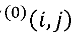 and the second prediction samples I^ i, j)
obtaining, at the decoder, second correlation values, wherein the second correlation values are a sum of the vertical gradient values based on the first prediction samples
 and the second prediction samples

modifying, at the decoder, the first correlation values by right shifting the first correlation values by 1; and
modifying, at the decoder, the second correlation values by right shifting the second correlation values by 1.
5. The method of claim 4, further comprising:
obtaining, at the decoder, first modified prediction samples by right shifting the first prediction samples
 using a second shift value;
obtaining, at the decoder, second modified prediction samples by right shifting the second prediction samples
 using the second shift value; and
obtaining, at the decoder, third correlation values, wherein the third correlation values
are a difference between the first modified prediction samples and the second modified prediction samples.
6. The method of claim 5, wherein the second shift value is equal to a coding bit-depth minus 8.
7. The method of claim 5, further comprising:
obtaining, at the decoder, a plurality of internal summation values based on the first correlation values, the second correlation values, and the third correlation values within each 4x4 sub-block of the video block.
8. The method of claim 7, further comprising:
obtaining, at the decoder, a horizontal motion refinement value based on at least one of the plurality of internal summation values, wherein motion refinement values comprise the horizontal motion refinement value;
obtaining, at the decoder, a vertical motion refinement value based on at least one of the plurality of internal summation values and the horizontal motion refinement value, wherein motion refinement values comprise the vertical motion refinement value; and
clipping, at the decoder, the horizontal motion refinement value and the vertical motion refinement value based on a motion refinement threshold.
9. The method of claim 8, further comprising:
obtaining, at the decoder, a horizontal gradient difference value, wherein the horizontal gradient difference value is the difference between a first horizontal gradient value and a second horizontal gradient value;
obtaining, at the decoder, a vertical gradient difference value, wherein the vertical gradient difference value is the difference between a first vertical gradient value and a second vertical gradient value;
left shifting, at the decoder, the horizontal gradient difference value by a third shift value;
left shifting, at the decoder, the vertical gradient difference value by the third shift value;
calculating, at the decoder, a sample refinement value based on a sum of a product of
the horizontal motion refinement value and the horizontal gradient difference value and a product of the vertical motion refinement value and the vertical gradient difference value; obtaining, at the decoder, the final bi-prediction samples of the video block based on a sum of the first prediction samples
 the second prediction samples I(l i,j). the sample refinement value, and an offset value; and
right shifting, at the decoder, the final bi-prediction samples by a fourth shift value.
10. The method of claim 9, wherein the third shift value is equal to a coding bit-depth minus 12.
11. A bit-depth control method of bi-directional optical flow (BDOF) for decoding a video signal, comprising:
obtaining, at a decoder, a first reference picture /(0) and a second reference picture / (1) associated with a video block, wherein the first reference picture
 is before a current picture and the second reference picture
 is after the current picture in display order; obtaining, at the decoder, first prediction samples I(0 i,j) of the video block from a reference block in the first reference picture I(0 wherein i and j represent a coordinate of one sample within the current picture;
obtaining, at the decoder, second prediction samples
 of the video block from a reference block in the second reference picture

controlling, at the decoder and when internal bit-depth is more than 12-bit, the internal bit-depths of the BDOF by applying right-shifting to internal BDOF parameters to align precision of an output prediction signal to a constant number, wherein the internal BDOF parameters comprising horizontal gradient values and vertical gradient values derived based on the first prediction samples
 the second prediction samples I(l i,j). and sample differences between the first prediction samples
 and the second prediction samples
obtaining, at the decoder, final bi-prediction samples of the video block based on the BDOF being applied to the video block based on the first prediction samples
 and the second prediction samples I^ i, j) and
obtaining, at the decoder, the output prediction signal based on the final bi-prediction
samples.
12. The method of claim 11, wherein controlling, when internal bit-depth is more than 12-bit, the internal bit-depths of the BDOF by applying right-shifting to the internal BDOF parameters to align the precision of the output prediction signal to a constant number comprises:
obtaining, at the decoder, a first horizontal gradient value of a first prediction sample /(0)(i,7) based on a difference between a first prediction sample
 (i + 1 ,j) and a first prediction sample

obtaining, at the decoder, a second horizontal gradient value of a second prediction sample based on a difference between a second prediction sample
 + 1 ,j) and a second prediction sample I^ i— 1 ,j)
obtaining, at the decoder, a first vertical gradient value of a first prediction sample based on a difference between a first prediction sample
 + 1) and a first prediction sample

obtaining, at the decoder, a second vertical gradient value of a second prediction sample based on a difference between a second prediction sample
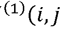 + 1) and a second prediction sample
 — 1);
— 1);
right shifting, at the decoder, the first and second horizontal gradient values by 10; and
right shifting, at the decoder, the first and second vertical gradient values by 10.
13. The method of claim 11, further comprising:
obtaining, at the decoder, first correlation values, wherein the first correlation values are a sum of the horizontal gradient values based on the first prediction samples
 and the second prediction samples I^ i, j)
obtaining, at the decoder, second correlation values, wherein the second correlation values are a sum of the vertical gradient values based on the first prediction samples
 and the second prediction samples

modifying, at the decoder, the first correlation values by right shifting the first correlation values by 1; and
modifying, at the decoder, the second correlation values by right shifting the second
correlation values by 1.
14. The method of claim 13, further comprising:
obtaining, at the decoder, first modified prediction samples by right shifting the first prediction samples

obtaining, at the decoder, second modified prediction samples by right shifting the second prediction samples
 by 8; and
obtaining, at the decoder, third correlation values, wherein the third correlation values are a difference between the first modified prediction samples and the second modified prediction samples.
15. The method of claim 14, further comprising:
obtaining, at the decoder, a plurality of internal summation values based on the first correlation values, the second correlation values, and the third correlation values within each 4x4 sub-block of the video block.
16. The method of claim 15, further comprising:
obtaining, at the decoder, a horizontal motion refinement value based on at least one of the plurality of internal summation values, wherein motion refinement values comprise the horizontal motion refinement value;
obtaining, at the decoder, a vertical motion refinement value based on at least one of the plurality of internal summation values and the horizontal motion refinement value, wherein motion refinement values comprise the vertical motion refinement value; and
clipping, at the decoder, the horizontal motion refinement value and the vertical motion refinement value based on a motion refinement threshold.
17. The method of claim 16, further comprising:
obtaining, at the decoder, a horizontal gradient difference value, wherein the horizontal gradient difference value is the difference between a first horizontal gradient value and a second horizontal gradient value;
obtaining, at the decoder, a vertical gradient difference value, wherein the vertical gradient difference value is the difference between a first vertical gradient value and a second
vertical gradient value;
left shifting, at the decoder, the horizontal gradient difference value by 4;
left shifting, at the decoder, the vertical gradient difference value by 4;
calculating a sample refinement value based on a sum of a product of the horizontal motion refinement value and the horizontal gradient difference value and a product of the vertical motion refinement value and the vertical gradient difference value;
obtaining, at the decoder, the final bi-prediction samples of the video block based on a sum of the first prediction samples
 the second prediction samples I(1 i,j). the sample refinement value, and an offset value; and
right shifting, at the decoder, the final bi-prediction samples by a shift value.
18. A computing device comprising:
one or more processors;
a non-transitory computer-readable storage medium storing instructions executable by the one or more processors, wherein the one or more processors are configured to:
obtain, at a decoder, a first reference picture /® and a second reference picture
 associated with a video block, wherein the first reference picture / (0) is before a current picture and the second reference picture
 is after the current picture in display order;
obtain, at the decoder, first prediction samples
 of the video block from a reference block in the first reference picture I(0 wherein i and j represent a coordinate of one sample within the current picture;
obtain, at the decoder, second prediction samples
 of the video block from a reference block in the second reference picture

control, at the decoder, internal bit-depths of bi-directional optical flow (BDOF) by applying right-shifting to internal BDOF parameters, wherein the BDOF is independent of an input video bit-depth, and wherein the internal BDOF parameters comprising horizontal gradient values and vertical gradient values derived based on the first prediction samples
 the second prediction samples I(1 i,j). and sample differences between the first prediction samples
 and the second prediction samples

obtain, at the decoder, final bi-prediction samples of the video block based on
the BDOF being applied to the video block based on the first prediction samples and the second prediction samples
19. The computing device of claim 18, wherein the one or more processors configured to control internal bit-depths of the BDOF by applying right-shifting to internal BDOF parameters are further configured to:
obtain, at the decoder, a first horizontal gradient value of a first prediction sample I(0 i,j) based on a difference between a first prediction sample
 (i + 1 ,j) and a first prediction sample

obtain, at the decoder, a second horizontal gradient value of a second prediction sample based on a difference between a second prediction sample I(1 i + 1 ,j) and a second prediction sample I^ i— 1 ,j)
obtain, at the decoder, a first vertical gradient value of a first prediction sample based on a difference between a first prediction sample
 + 1) and a first prediction sample

obtain, at the decoder, a second vertical gradient value of a second prediction sample based on a difference between a second prediction sample
 + 1) and a second prediction sample

right shift, at the decoder, the first and second horizontal gradient values by a first shift value; and
right shift, at the decoder, the first and second vertical gradient values by the first shift value.
20. The computing device of claim 19, wherein the first shift value is equal to a coding bit-depth minus 6.
21. The computing device of claim 18, wherein the one or more processors are further configured to:
obtain, at the decoder, first correlation values, wherein the first correlation values are a sum of the horizontal gradient values based on the first prediction samples
 and the second prediction samples I^ i, j)
obtain, at the decoder, second correlation values, wherein the second correlation
values are a sum of the vertical gradient values based on the first prediction samples
 and the second prediction samples
modify, at the decoder, the first correlation values by right shifting the first correlation values by 1 ; and
modify, at the decoder, the second correlation values by right shifting the second correlation values by 1.
22. The computing device of claim 21, wherein the one or more processors are further configured to:
obtain, at the decoder, first modified prediction samples by right shifting the first prediction samples
 using a second shift value;
obtain, at the decoder, second modified prediction samples by right shifting the second prediction samples
 using the second shift value; and
obtain, at the decoder, third correlation values, wherein the third correlation values are a difference between the first modified prediction samples and the second modified prediction samples.
23. The computing device of claim 22, wherein the second shift value is equal to a coding bit-depth minus 8.
24. The computing device of claim 22, wherein the one or more processors are further configured to:
obtain, at the decoder, a plurality of internal summation values based on the first correlation values, the second correlation values, and the third correlation values within each 4x4 sub-block of the video block.
25. The computing device of claim 24, further comprising:
obtain, at the decoder, a horizontal motion refinement value based on at least one of the plurality of internal summation values, wherein motion refinement values comprise the horizontal motion refinement value;
obtain, at the decoder, a vertical motion refinement value based on at least one of the plurality of internal summation values and the horizontal motion refinement value, wherein
motion refinement values comprise the vertical motion refinement value; and clip, at the decoder, the horizontal motion refinement value and the vertical motion refinement value based on a motion refinement threshold.
26. The computing device of claim 25 wherein the one or more processors are further configured to:
obtain, at the decoder, a horizontal gradient difference value, wherein the horizontal gradient difference value is the difference between a first horizontal gradient value and a second horizontal gradient value;
obtain, at the decoder, a vertical gradient difference value, wherein the vertical gradient difference value is the difference between a first vertical gradient value and a second vertical gradient value;
left shift, at the decoder, the horizontal gradient difference value by a third shift value; left shift, at the decoder, the vertical gradient difference value by the third shift value; calculate, at the decoder, a sample refinement value based on a sum of a product of the horizontal motion refinement value and the horizontal gradient difference value and a product of the vertical motion refinement value and the vertical gradient difference value; obtain, at the decoder, the final bi-prediction samples of the video block based on a sum of the first prediction samples
 the second prediction samples I(1 i,j). the sample refinement value, and an offset value; and
right shift, at the decoder, the final bi-prediction samples by a fourth shift value.
27. The computing device of claim 26, wherein the third shift value is equal to a coding bit-depth minus 12.
28. A non-transitory computer-readable storage medium storing a plurality of programs for execution by a computing device having one or more processors, wherein the plurality of programs, when executed by the one or more processors, cause the computing device to perform acts comprising:
obtaining, at a decoder, a first reference picture /(0) and a second reference picture / (1) associated with a video block, wherein the first reference picture
 is before a current picture and the second reference picture is after the current picture in display order;
obtaining, at the decoder, first prediction samples I(0 i,j) of the video block from a reference block in the first reference picture I(0 wherein i and j represent a coordinate of one sample within the current picture;
is before a current picture and the second reference picture is after the current picture in display order;
obtaining, at the decoder, first prediction samples I(0 i,j) of the video block from a reference block in the first reference picture I(0 wherein i and j represent a coordinate of one sample within the current picture;
obtaining, at the decoder, second prediction samples
 of the video block from a reference block in the second reference picture

controlling, at the decoder and when internal bit-depth is more than 12-bit, the internal bit-depths of bi-directional optical flow (BDOF) by applying right-shifting to internal BDOF parameters to align precision of an output prediction signal to a constant number, wherein the internal BDOF parameters comprising horizontal gradient values and vertical gradient values derived based on the first prediction samples
 (1,7), the second prediction samples and sample differences between the first prediction samples I(0 i,j) and the second prediction samples

obtaining, at the decoder, final bi-prediction samples of the video block based on the BDOF being applied to the video block based on the first prediction samples
 and the second prediction samples I^ i, 7); and
obtaining, at the decoder, the output prediction signal based on the final bi-prediction samples.
29. The non-transitory computer-readable storage medium of claim 28, wherein the plurality of programs further cause the computing device to perform:
obtaining, at the decoder, a first horizontal gradient value of a first prediction sample I(0 i,j) based on a difference between a first prediction sample /®(i + 1 ,7) and a first prediction sample I(0 i— 1 ,7);
obtaining, at the decoder, a second horizontal gradient value of a second prediction sample based on a difference between a second prediction sample I(l i + l,j) and a second prediction sample I^ i— l,j)
obtaining, at the decoder, a first vertical gradient value of a first prediction sample based on a difference between a first prediction sample
 + 1) and a first prediction sample

obtaining, at the decoder, a second vertical gradient value of a second prediction sample based on a difference between a second prediction sample
 + 1) and
a second prediction sample
+ 1) and
a second prediction sample
 — 1);
— 1);
right shifting, at the decoder, the first and second horizontal gradient values by 10; and
right shifting, at the decoder, the first and second vertical gradient values by 10.
30. The non-transitory computer-readable storage medium of claim 28, wherein the plurality of programs further cause the computing device to perform:
obtaining, at the decoder, first correlation values, wherein the first correlation values are a sum of the horizontal gradient values based on the first prediction samples
 and the second prediction samples I^ i, j)
obtaining, at the decoder, second correlation values, wherein the second correlation values are a sum of the vertical gradient values based on the first prediction samples
 and the second prediction samples

modifying, at the decoder, the first correlation values by right shifting the first correlation values by 1; and
modifying, at the decoder, the second correlation values by right shifting the second correlation values by 1.
31. The non-transitory computer-readable storage medium of claim 30, wherein the plurality of programs further cause the computing device to perform:
obtaining, at the decoder, first modified prediction samples by right shifting the first prediction samples

obtaining, at the decoder, second modified prediction samples by right shifting the second prediction samples
 by 8; and
obtaining, at the decoder, third correlation values, wherein the third correlation values are a difference between the first modified prediction samples and the second modified prediction samples.
32. The non-transitory computer-readable storage medium of claim 31, wherein the plurality of programs further cause the computing device to perform:
obtaining, at the decoder, a plurality of internal summation values based on the first correlation values, the second correlation values, and the third correlation values within each
4x4 sub-block of the video block.
33. The non-transitory computer-readable storage medium of claim 32, further comprising:
obtaining, at the decoder, a horizontal motion refinement value based on at least one of the plurality of internal summation values, wherein motion refinement values comprise the horizontal motion refinement value;
obtaining, at the decoder, a vertical motion refinement value based on at least one of the plurality of internal summation values and the horizontal motion refinement value, wherein motion refinement values comprise the vertical motion refinement value; and
clipping, at the decoder, the horizontal motion refinement value and the vertical motion refinement value based on a motion refinement threshold.
34. The non-transitory computer-readable storage medium of claim 33, wherein the plurality of programs further cause the computing device to perform:
obtaining, at the decoder, a horizontal gradient difference value, wherein the horizontal gradient difference value is the difference between a first horizontal gradient value and a second horizontal gradient value;
obtaining, at the decoder, a vertical gradient difference value, wherein the vertical gradient difference value is the difference between a first vertical gradient value and a second vertical gradient value;
left shifting, at the decoder, the horizontal gradient difference value by 4;
left shifting, at the decoder, the vertical gradient difference value by 4;
calculating, at the decoder, a sample refinement value based on a sum of the product of the horizontal motion refinement value and the horizontal gradient difference value and a product of the vertical motion refinement value and the vertical gradient difference value; obtaining, at the decoder, the final bi-prediction samples of the video block based on a sum of the first prediction samples
 the second prediction samples I(l i,j). the sample refinement value, and an offset value; and
right shifting, at the decoder, the final bi-prediction samples by a shift value.
Priority Applications (1)
| Application Number | Priority Date | Filing Date | Title |
|---|---|---|---|
| CN202080045432.8A CN114175659B (en) | 2019-06-25 | 2020-06-25 | Apparatus and method for bit depth control of bidirectional optical flow |
Applications Claiming Priority (4)
| Application Number | Priority Date | Filing Date | Title |
|---|---|---|---|
| US201962866607P | 2019-06-25 | 2019-06-25 | |
| US62/866,607 | 2019-06-25 | ||
| US201962867185P | 2019-06-26 | 2019-06-26 | |
| US62/867,185 | 2019-06-26 |
Publications (1)
| Publication Number | Publication Date |
|---|---|
| WO2020264221A1 true WO2020264221A1 (en) | 2020-12-30 |
Family
ID=74061322
Family Applications (1)
| Application Number | Title | Priority Date | Filing Date |
|---|---|---|---|
| PCT/US2020/039702 Ceased WO2020264221A1 (en) | 2019-06-25 | 2020-06-25 | Apparatuses and methods for bit-width control of bi-directional optical flow |
Country Status (2)
| Country | Link |
|---|---|
| CN (1) | CN114175659B (en) |
| WO (1) | WO2020264221A1 (en) |
Cited By (1)
| Publication number | Priority date | Publication date | Assignee | Title |
|---|---|---|---|---|
| EP3891990A4 (en) * | 2019-01-06 | 2022-06-15 | Beijing Dajia Internet Information Technology Co., Ltd. | Bit-width control for bi-directional optical flow |
Citations (2)
| Publication number | Priority date | Publication date | Assignee | Title |
|---|---|---|---|---|
| WO2016054765A1 (en) * | 2014-10-08 | 2016-04-14 | Microsoft Technology Licensing, Llc | Adjustments to encoding and decoding when switching color spaces |
| EP3413563A1 (en) * | 2016-02-03 | 2018-12-12 | Sharp Kabushiki Kaisha | Moving image decoding device, moving image encoding device, and prediction image generation device |
Family Cites Families (6)
| Publication number | Priority date | Publication date | Assignee | Title |
|---|---|---|---|---|
| KR100890512B1 (en) * | 2008-09-11 | 2009-03-26 | 엘지전자 주식회사 | How to determine motion vector |
| EP2661892B1 (en) * | 2011-01-07 | 2022-05-18 | Nokia Technologies Oy | Motion prediction in video coding |
| WO2017036399A1 (en) * | 2015-09-02 | 2017-03-09 | Mediatek Inc. | Method and apparatus of motion compensation for video coding based on bi prediction optical flow techniques |
| WO2018230493A1 (en) * | 2017-06-14 | 2018-12-20 | シャープ株式会社 | Video decoding device, video encoding device, prediction image generation device and motion vector derivation device |
| US10904565B2 (en) * | 2017-06-23 | 2021-01-26 | Qualcomm Incorporated | Memory-bandwidth-efficient design for bi-directional optical flow (BIO) |
| KR102580910B1 (en) * | 2017-08-29 | 2023-09-20 | 에스케이텔레콤 주식회사 | Motion Compensation Method and Apparatus Using Bi-directional Optical Flow |
-
2020
- 2020-06-25 CN CN202080045432.8A patent/CN114175659B/en active Active
- 2020-06-25 WO PCT/US2020/039702 patent/WO2020264221A1/en not_active Ceased
Patent Citations (2)
| Publication number | Priority date | Publication date | Assignee | Title |
|---|---|---|---|---|
| WO2016054765A1 (en) * | 2014-10-08 | 2016-04-14 | Microsoft Technology Licensing, Llc | Adjustments to encoding and decoding when switching color spaces |
| EP3413563A1 (en) * | 2016-02-03 | 2018-12-12 | Sharp Kabushiki Kaisha | Moving image decoding device, moving image encoding device, and prediction image generation device |
Non-Patent Citations (3)
| Title |
|---|
| BENJAMIN BROSS et al., Versatile Video Coding (Draft 5), Joint Video Experts Team (JVET) of ITU-T SG 16 WP 3 and ISO/IEC JTC 1/SC 29/WG 11, [Document: JVET-N1001-v7 (Version 7)], 14th Meeting: Geneva, CH, PP. 1-371, 29 May 2019 [Retrieved on 10-Sep-2020], from <http://phenix.int-evry.fr/jvet/> pages 222-223 * |
| JIANCONG (DANIEL) LUO et al., CE2-related: Prediction refinement with optical flow for affine mode, Joint Video Experts Team (JVET) of ITU-T SG 16 WP 3 and ISO/IEC JTC 1/SC 29/WG 11, [Document: JVET-N0236-r5 (Version 7)], 14th Meeting: Geneva, CH, PP. 1-7, 26 March 2019 [Retrieved on 10-Sep-2020], from <http://phenix.int-evry.fr/jvet/> pages 1-4 * |
| XIAOYU XIU et al., CE9-related: Improvements on bi-directional optical flow (BDOF), Joint Video Experts Team (JVET) of ITU-T SG 16 WP 3 and ISO/IEC JTC 1/SC 29/WG 11, [Document: JVET-N0325 (Version 3)], 14th Meeting: Geneva, CH, 26 March 2019 [Retrieved on 10-Sep-2020], from <http://phenix.int-evry.fr/jvet/> pages 1-2, 4 * |
Cited By (5)
| Publication number | Priority date | Publication date | Assignee | Title |
|---|---|---|---|---|
| EP3891990A4 (en) * | 2019-01-06 | 2022-06-15 | Beijing Dajia Internet Information Technology Co., Ltd. | Bit-width control for bi-directional optical flow |
| US11388436B2 (en) | 2019-01-06 | 2022-07-12 | Beijing Dajia Internet Information Technology Co., Ltd. | Bit-width control for bi-directional optical flow |
| US11743493B2 (en) | 2019-01-06 | 2023-08-29 | Beijing Dajia Internet Information Technology Co., Ltd. | Bit-width control for bi-directional optical flow |
| US12137244B2 (en) | 2019-01-06 | 2024-11-05 | Beijing Dajia Internet Information Technology Co., Ltd. | Bit-width control for bi-directional optical flow |
| US12238331B2 (en) | 2019-01-06 | 2025-02-25 | Beijing Dajia Internet Information Technology Co., Ltd. | Bit-width control for bi-directional optical flow |
Also Published As
| Publication number | Publication date |
|---|---|
| CN114175659B (en) | 2026-02-13 |
| CN114175659A (en) | 2022-03-11 |
Similar Documents
| Publication | Publication Date | Title |
|---|---|---|
| US12341973B2 (en) | Methods and devices for bit-width control for bi-directional optical flow | |
| JP7463460B2 (en) | Video decoding method and video decoder | |
| KR20210099008A (en) | Method and apparatus for deblocking an image | |
| EP3891990A1 (en) | Bit-width control for bi-directional optical flow | |
| WO2021041332A1 (en) | Methods and apparatus on prediction refinement with optical flow | |
| WO2021072326A1 (en) | Methods and apparatuses for prediction refinement with optical flow, bi-directional optical flow, and decoder-side motion vector refinement | |
| WO2020220048A1 (en) | Methods and apparatuses for prediction refinement with optical flow | |
| EP4032298A1 (en) | Methods and apparatus for prediction refinement with optical flow | |
| EP3991431A1 (en) | Methods and apparatus on prediction refinement with optical flow | |
| EP3909241A1 (en) | System and method for improving combined inter and intra prediction | |
| WO2020257629A1 (en) | Methods and apparatus for prediction refinement with optical flow | |
| WO2020223552A1 (en) | Methods and apparatus of prediction refinement with optical flow | |
| WO2020264221A1 (en) | Apparatuses and methods for bit-width control of bi-directional optical flow | |
| WO2021188707A1 (en) | Methods and apparatuses for simplification of bidirectional optical flow and decoder side motion vector refinement | |
| CN113615197B (en) | Method and apparatus for bit depth control of bi-directional optical flow | |
| WO2020159990A1 (en) | Methods and apparatus on intra prediction for screen content coding |
Legal Events
| Date | Code | Title | Description |
|---|---|---|---|
| 121 | Ep: the epo has been informed by wipo that ep was designated in this application |
Ref document number: 20831137 Country of ref document: EP Kind code of ref document: A1 |
|
| NENP | Non-entry into the national phase |
Ref country code: DE |
|
| 122 | Ep: pct application non-entry in european phase |
Ref document number: 20831137 Country of ref document: EP Kind code of ref document: A1 |