WO2020263254A1 - Wideband filter with cascaded coupled acoustic resonators and shunt reactive elements - Google Patents
Wideband filter with cascaded coupled acoustic resonators and shunt reactive elements Download PDFInfo
- Publication number
- WO2020263254A1 WO2020263254A1 PCT/US2019/039363 US2019039363W WO2020263254A1 WO 2020263254 A1 WO2020263254 A1 WO 2020263254A1 US 2019039363 W US2019039363 W US 2019039363W WO 2020263254 A1 WO2020263254 A1 WO 2020263254A1
- Authority
- WO
- WIPO (PCT)
- Prior art keywords
- acoustic wave
- filter
- denoting
- wave resonators
- coupling
- Prior art date
- Legal status (The legal status is an assumption and is not a legal conclusion. Google has not performed a legal analysis and makes no representation as to the accuracy of the status listed.)
- Ceased
Links
Classifications
-
- H—ELECTRICITY
- H03—ELECTRONIC CIRCUITRY
- H03H—IMPEDANCE NETWORKS, e.g. RESONANT CIRCUITS; RESONATORS
- H03H9/00—Networks comprising electromechanical or electro-acoustic elements; Electromechanical resonators
- H03H9/46—Filters
- H03H9/54—Filters comprising resonators of piezoelectric or electrostrictive material
- H03H9/542—Filters comprising resonators of piezoelectric or electrostrictive material including passive elements
-
- H—ELECTRICITY
- H03—ELECTRONIC CIRCUITRY
- H03H—IMPEDANCE NETWORKS, e.g. RESONANT CIRCUITS; RESONATORS
- H03H9/00—Networks comprising electromechanical or electro-acoustic elements; Electromechanical resonators
- H03H9/46—Filters
- H03H9/48—Coupling means therefor
- H03H9/52—Electric coupling means
- H03H9/525—Electric coupling means for microelectro-mechanical filters
-
- H—ELECTRICITY
- H03—ELECTRONIC CIRCUITRY
- H03H—IMPEDANCE NETWORKS, e.g. RESONANT CIRCUITS; RESONATORS
- H03H9/00—Networks comprising electromechanical or electro-acoustic elements; Electromechanical resonators
- H03H9/46—Filters
- H03H9/54—Filters comprising resonators of piezoelectric or electrostrictive material
- H03H9/56—Monolithic crystal filters
- H03H9/566—Electric coupling means therefor
-
- H—ELECTRICITY
- H03—ELECTRONIC CIRCUITRY
- H03H—IMPEDANCE NETWORKS, e.g. RESONANT CIRCUITS; RESONATORS
- H03H9/00—Networks comprising electromechanical or electro-acoustic elements; Electromechanical resonators
- H03H9/46—Filters
- H03H9/54—Filters comprising resonators of piezoelectric or electrostrictive material
- H03H9/58—Multiple crystal filters
- H03H9/60—Electric coupling means therefor
-
- H—ELECTRICITY
- H03—ELECTRONIC CIRCUITRY
- H03H—IMPEDANCE NETWORKS, e.g. RESONANT CIRCUITS; RESONATORS
- H03H9/00—Networks comprising electromechanical or electro-acoustic elements; Electromechanical resonators
- H03H9/46—Filters
- H03H9/64—Filters using surface acoustic waves
- H03H9/6423—Means for obtaining a particular transfer characteristic
- H03H9/6433—Coupled resonator filters
-
- H—ELECTRICITY
- H03—ELECTRONIC CIRCUITRY
- H03H—IMPEDANCE NETWORKS, e.g. RESONANT CIRCUITS; RESONATORS
- H03H9/00—Networks comprising electromechanical or electro-acoustic elements; Electromechanical resonators
- H03H9/46—Filters
- H03H9/64—Filters using surface acoustic waves
- H03H9/6423—Means for obtaining a particular transfer characteristic
- H03H9/6433—Coupled resonator filters
- H03H9/6479—Capacitively coupled SAW resonator filters
-
- H—ELECTRICITY
- H03—ELECTRONIC CIRCUITRY
- H03H—IMPEDANCE NETWORKS, e.g. RESONANT CIRCUITS; RESONATORS
- H03H9/00—Networks comprising electromechanical or electro-acoustic elements; Electromechanical resonators
- H03H9/24—Constructional features of resonators of material which is not piezoelectric, electrostrictive, or magnetostrictive
- H03H9/2405—Constructional features of resonators of material which is not piezoelectric, electrostrictive, or magnetostrictive of microelectro-mechanical resonators
- H03H2009/241—Bulk-mode MEMS resonators
-
- H—ELECTRICITY
- H03—ELECTRONIC CIRCUITRY
- H03H—IMPEDANCE NETWORKS, e.g. RESONANT CIRCUITS; RESONATORS
- H03H9/00—Networks comprising electromechanical or electro-acoustic elements; Electromechanical resonators
- H03H9/02—Details
- H03H9/02228—Guided bulk acoustic wave devices or Lamb wave devices having interdigital transducers situated in parallel planes on either side of a piezoelectric layer
-
- H—ELECTRICITY
- H03—ELECTRONIC CIRCUITRY
- H03H—IMPEDANCE NETWORKS, e.g. RESONANT CIRCUITS; RESONATORS
- H03H9/00—Networks comprising electromechanical or electro-acoustic elements; Electromechanical resonators
- H03H9/46—Filters
- H03H9/54—Filters comprising resonators of piezoelectric or electrostrictive material
- H03H9/58—Multiple crystal filters
- H03H9/582—Multiple crystal filters implemented with thin-film techniques
- H03H9/583—Multiple crystal filters implemented with thin-film techniques comprising a plurality of piezoelectric layers acoustically coupled
- H03H9/585—Stacked Crystal Filters [SCF]
-
- H—ELECTRICITY
- H03—ELECTRONIC CIRCUITRY
- H03H—IMPEDANCE NETWORKS, e.g. RESONANT CIRCUITS; RESONATORS
- H03H9/00—Networks comprising electromechanical or electro-acoustic elements; Electromechanical resonators
- H03H9/46—Filters
- H03H9/64—Filters using surface acoustic waves
- H03H9/6423—Means for obtaining a particular transfer characteristic
- H03H9/6426—Combinations of the characteristics of different transducers
Definitions
- Examples relate to Acoustic Wave Resonator (AWR) based filters.
- examples relate to a filter and a mobile device comprising the filter.
- FEM Front-End Module
- Front-end filtering is the first line of defense in protecting the user equipment and network against the barrage of unwanted signals (interference) and ambient noise.
- AWRs based on MicroElectroMechanical Systems (MEMS) are basic building blocks and unrivalled in com ing close to satisfying the stringent insertion loss, sharpness, and form-factor filtering require ments for cellular technology.
- Traditional AWR filters are faced with a serious challenge in meeting, e.g., the 5 th Generation New Radio (5G NR) bandwidth requirements.
- 5G NR 5 th Generation New Radio
- MEMS resonators have an anti-resonance (parallel resonance at frequency f pr ) occurring at a frequency that closely follows the resonance frequency (series resonance frequency f sr ).
- the series L m C m in the mo tional branch is responsible for the resonance and its combination with a parallel electro-static capacitance produces the anti-resonance.
- Af and thus the bandwidth ( BW ) of a conventional AWR ladder filter are determined by the resonator“electro-mechan ical transduction” or“electro-mechanical coupling” coefficient k as can be seen from the following mathematical expression: Accordingly, the fractional bandwidth FBW of a conventional AWR ladder filter is deter mined by k 2 as can be seen from the following mathematical expression:
- k 2 The value of k 2 is highly dependent on the type of piezo-electric material, and ranges from ⁇ 5 X 10 -3 or 0.5% to ⁇ 7 X 10 -2 or 7% for industry standard materials such as PZT, AIN or ZnO. More recently, expensive exotic materials such as Lithium Niobate have been used with over 30% k 2 . Other factors such as resonator type and physical structure, metal electrode shape and thickness, and filter structure can also play significant roles in the achievable filter bandwidth k 2 ⁇ in mathematical expression (2) is the effective electro-acoustic coefficient, taking all such effects into account.
- Fig. 1 illustrates an example of an AWR based filter
- Fig. 2 illustrates another example of an AWR based filter
- Fig. 3 illustrates a further example of an AWR based filter
- Fig. 4 illustrates an example of a three-terminal resonator
- Fig. 5 illustrates an example of a BYD model for a three-terminal resonator
- Fig. 6 illustrates an example of a contour mode resonator
- Fig. 7 illustrates an example of a mobile device comprising an AWR based filter.
- Fig. 1 illustrates an example of a filter 100 comprising a cascade of coupled AWRs 110-1
- the cascade of coupled AWRs 110-1, ... , 110-N may comprise any number N > 2 of AWRs 110-1, ..., 110-N.
- the number of AWRs may, e.g., be equal to the desired order of the filter 100.
- a third order filter may comprise a cascade of three coupled AWRs, whereas a fifth order filter may comprise a cascade of five coupled AWRs.
- the AWRs 110-1, ... , 110-N are three-terminal resonators. Three-terminal resonators are also denoted as two-port resistors.
- An exemplary three-terminal AWR 110-i is illustrated in Fig. 4.
- the three-terminal AWR 110-i comprises an input terminal 111 for receiving an input sig nal for the resonator, an output terminal 112 for outputting an output signal of the resonator, and a ground terminal 113 for coupling to ground.
- the terminals 111 to 113 interact through a medium 114.
- the medium 114 may be piezo-electric medium (material).
- the three-terminal AWR 110-i may be a MEMS resonator.
- the circuit 500 comprises a motional branch comprising an inductive element 501 exhibiting a motional inductance L M , a capacitive element 502 exhibiting a mo tional capacitance C M and a resistive element 503 (for modelling the acoustic loss) exhibiting a motional resistance R M coupled in series between an input terminal 511 for receiving an input signal and an output terminal 512 for outputting an output signal of the resonator.
- the capacitive elements 504 and 505 exhibit a capacitance C 0 for modeling the static ground ca pacitance (i.e. the intrinsic capacitance of the resonator).
- the capacitive element 506 is cou pled in parallel to the motional branch and exhibits a feedthrough capacitance 6 t for model ling parasitic capacitances through the medium of the resonator.
- one of the three terminals of each AWR 110-1, ... , 110-N is coupled to ground similar to what is described above for three-terminal AWR 110-i illustrated in Fig. 4.
- the AWRs 110-1, ... , 110-N may be any type of AWR.
- 110-N may be acoustic wave MEMS resonators.
- the cascaded AWRs 110-1, ... , 110-N are of the same resonator type.
- the cascaded AWRs 110-1, ..., 110-N may exhibit the same or different resonance frequencies f R and the same input impedance Z R .
- the cascaded AWRs 110-1, ..., 110-N may be identical.
- the resonance frequency (frequencies) f R of the AWRs 110-1, ... , 110-N is/are different from a desired center frequency f s of the filter 100.
- the filter 100 further comprises a plurality of coupling structures 140-1, ... , 140-N+l each coupled to a respective one of a plurality of conductive paths 180-1, ... , 180-N+l.
- the plurality of conductive paths 180-1, ..., 180-N+l couple pairs of con secutive (directly succeeding) AWRs of the cascade of AWRs 110-1, ... , 110-N (e.g. AWRs 110-1 and 110-2), the input terminal 120 and the first AWR 110-1 of the cascade of AWRs 110-1, ... , 110-N, and the output terminal 130 and the last AWR 110-N of the cascade of AWRs 110-1, ... , 110-N.
- each of the plurality of coupling structures 140-1, ... , 140-N+l consists of (only, solely, exclusively) a single passive reactive element 150-1, ... , 150-N+l coupled be tween ground and the respective conductive path 180-1, ..., 180-N+l .
- the coupling structures may comprise more than one passive reactive element or zero passive reactive elements.
- the coupling structures 140-1, ... , 140-N+l are reactive inter-stage coupling components for coupling the AWRs 110-1, ... , 110-N.
- the number of coupling structures is N+l, i.e. it depends on the number N of cascaded AWRs.
- the passive reactive element 150-1, ..., 150-N+l is a passive (i.e. not active) electric element that tries to resist a change in voltage or current in the filter (circuit) 100.
- the passive reactive ele ments 150-1, ... , 150-N+l may be capacitive elements or inductive elements.
- the filter 100 further comprises a first inductive element 160 coupled between the input ter minal 120 and the first AWR 110-1 of the cascade of AWRs 110-1, ..., 110-N.
- a second inductive element 170 is coupled between the output terminal 130 and the last AWR 110-N of the cascade of AWRs 110-1, 110-N.
- 170 are for matching the input and output impedance of the filter 100.
- Filter 100 may be understood as a cascaded three-terminal (two-port) resonator array with single shunt inter-stage reactive couplings (e.g. capacitive or inductive).
- the structure of the filter 100 may allow a k agnostic passband characteristic of the filter 100.
- k agnostic passband characteristic of the filter 100 means that the passband characteristic of the filter 100 is not limited by the electro-mechanical coupling coefficient k of the AWRs 110- 1, ... , 110-N.
- a desired bandwidth of the filter 100 is not limited by the electro mechanical coupling coefficient k of the AWRs 110-1, ..., 110-N.
- the filter model deter mining the filter characteristic of the filter 100 is selected based on a desired insertion loss (e.g. passband or ripple) of the filter 100.
- the filter model may be a Butterworth- filter, a Chebyshev-filter, an Elliptic-filter etc.
- the polynomial coefficients g t may, e.g., be taken from a look-up table or a polynomial of order N with the polynomial coefficients g t may be determined for the desired band-pass performance.
- the coupling structures 140-1, 140-N+l may be understood as coupling inverters since they effectively behave like inverters coupling the AWRs 110-1, ... , 110-N.
- the (inverter) coupling coefficients K t are de-normalized for the desired frac tional bandwidth FBW of the filter 100 (i.e. the ratio of the desired bandwidth Af of the filter 100 to the desired center frequency f s of the filter 100).
- the de-normalization is done using the two following mathematical expressions:
- L m denotes the motional inductance in the equivalent BVD circuit for modelling the behavior of the AWRs 110-1, ... , 110-N.
- Lf denotes the low-pass motional inductance.
- R s denotes the resistance of a signal source (not illustrated in Fig. 1) providing the input signal to the input node 120 of the filter 100.
- R L denotes the resistance of a load (not illustrated in Fig. 1) coupled to the output node 130 of the filter 100.
- the coupling capacitances of the coupling structures 140-1, ... , 140-N+l for coupling the AWRs 110-1, ..., 110-N are determined using the following mathematical expression:
- C 0 denoting the (input/output) electro-static capacitance of the AWRs 110-1, .. 110-N, and Z 0 denoting the desired characteristic impedance of the filter 100 (assuming a symmetric resonator structure; for a non-symmetric structure, e.g., an unequal of input/output fingers, the term 2 C 0 in mathematical expression (6) may be replaced by C o input + C Q-output ).
- the resonance frequency (frequencies) f R of the individual AWRs 110- 1, ..., 110-N may be different from (i.e. shifted w.r.t) the desired center frequency f s of the filter 100.
- the average shifted resonance frequency of the AWRs 110-1, ... , 110-N is deter mined using the following mathematical expressions: and
- the passive reactive elements 150-1, ..., 150-N+l are capacitive elements exhibiting the respective determined capacitance C t .
- the passive reactive elements 150-1, ..., 150-N+l are inductive elements exhibiting the re spective determined inductance L t .
- the inductances L s and L L of the first and last inductive elements 160 and 170 are determined.
- the inductances L s and L L of the first inductive element 160 and the last in ductive element 170 are proportional to an inverse of a square of the desired center frequency f s of the filter 100 and an inverse of the capacitance C t of the passive reactive element 150- 1/150-N+l of the coupling structure 140-1/140-N+l coupled to the conductive path 180- 1/180-N+l coupling the input terminal 120 and the first AWR 110-1 of the cascade of AWRs 110-1, ... , 110-N or coupling the output terminal 130 and the last AWR 110-1 of the cascade of AWRs 110-1, ... , 110-N.
- the determined values for the passive elements of filter 100 may be optimized (e.g. using a Minimum Mean Square Error, MMSE, estimation) to tweak the determined val ues for performance.
- MMSE Minimum Mean Square Error
- a computer-aided optimization of the determined values for the passive elements of filter 100 may be done.
- the filter 100 is based on several approximations. For example, one assumption may be that Cf t « C 0 may be ignored in combining components such as three-terminal AWRs (e.g. made of piezo-electric material). Another assumption may be that the mathematical expression (3) used for determining the coupling coefficients K t varies for less than the polynomial coeffi cients g t of the underlying filter model such as e.g. a Butterworth-filter, a Chebyshev-filter, etc. (for example, the polynomial coefficients g may vary from ⁇ 0.5 to ⁇ 3— 4 in common band-pass polynomials).
- the individual angular resonance frequencies a> s i do not fluctuate much between the AWRs 110-1, 110-N.
- This allows for the uniform topology with a single AWR resonance frequency f R such that: f R fs - fs (11), wherein Af s is defined as follows: with Af s. denoting the individual frequency deviation of each of the AWRs 110-1, ... , 110-N from the desired center frequency f s of the filter 100.
- AWRs 110-1, 110-N are described as identical such that they exhibit the same resonance fre quency f R , there may be slight differences between the individual AWRs 110-1, 110-N due to manufacturing tolerances etc.
- CM -u> S P ' CO ' U>S mathematical expression (13) may be rewritten as follows: Further, the angular resonance frequency ⁇ 3 ⁇ 4 of the AWRs 110-1, ..., 110-N may be defined as follows: i
- the input impedance of the AWRs 110-1, ... , 110-N may be defined as follows:
- the inductance of the passive reac tive elements goes down for a larger fractional bandwidth FBW and/or a smaller electro mechanical coupling coefficient k of the AWRs 110-1, ... , 110-N.
- the in ductance of the first and second matching inductors 160 and 170 goes up for a larger fractional bandwidth FBW and/or a smaller electro-mechanical coupling coefficient k of the AWRs 110-1, ... , 110-N.
- C S L denoting the capacitance of the first and last inductive elements 160 and 170
- K S L denoting the coupling coefficient of the first and last inductive elements 160 and 170.
- the desired bandwidth of the filter 100 is not limited by the electro-mechanical coupling coefficient k ⁇ .
- the desired bandwidth of the filter 100 may be adjusted by selecting appropriate capacitance/inductance values for the passive reactive elements 150-1, ... , 150-N+l and the first and second matching inductors 160 and 170.
- the high-performance (broad-band) individual resonance frequency of an AWR is typically thickness dependent and multiple frequency operation cannot be integrated.
- AWR types that are not thickness dependent and can be integrated for multiple frequencies e.g surface acous tic wave resonators, or contour mode resonators
- w.r.t electro-mechanical coupling coefficient k e.g. up to only 2%) and thus in filter bandwidth.
- the proposed filter architec ture provides a topology and formal means to synthesize high-performance integrated AWR filters with substantially broad bandwidth independent of the resonators’ electro-mechanical coupling coefficient k .
- the proposed topology may use only a single resonator type (same res onance frequency and input impedance). Further the used AWRs do not require costly trim ming for a high precision resonance frequency. Further, unlike other proposed hybrid tech niques, the proposed topology calls for only one passive reactive component per stage for inter-stage coupling.
- Fig. 2 illustrates a filter 200 that is identical to above described filter 100, wherein the passive reactive elements 150-1, ... , 150-N+l are implemented as capacitive elements 250-1, ... , 250- N+l .
- the capacitive elements 250-1 and 250-N+l may exhibit a capacitance as given in above mathematical expressions (6) and (25).
- the capacitive elements 250- 1 and 250-N+l may exhibit a capacitance proportional to an expression which is mathemati cally correspondent to: with a L denoting a constant for the respective capacitive element.
- the coupling coefficient K t of the respective capacitive element 250-1 or 250-N+l for coupling the first or the last AWR of the cascade of AWRs 110-1, ... , 110-N is proportional to an inverse of a square root of a product of polynomial coefficients of a filter model determining the filter characteristic of the filter 200 (see above mathematical expres sion (3)), wherein one of the polynomial coefficients of the filter model is assigned to the first or the last AWR of the cascade of AWRs 110-1, ... , 110-N.
- the capacitive elements 250-2 to 250-N may exhibit a capacitance as given in above mathe matical expressions (6) and (22).
- the capacitive elements 250-2 to 250-N may exhibit a capacitance proportional to an expression which is mathematically cor respondent to: with a denoting a constant.
- the coupling coefficient K L of the respective capacitive element 250-2 to 250-N for coupling the pair of consecutive AWRs is propor tional to an inverse of a square root of a product of polynomial coefficients of a filter model determining the filter characteristic of the filter (see above mathematical expression (3)), wherein the polynomial coefficients of the filter model are assigned to the pair of consecutive AWRs.
- a signal source 280 providing an input signal for the filter 200.
- the signal source 280 is coupled to the input terminal 120 of the filter 200.
- the signal source 280 is illustrated schematically in Fig. 2 by means of a resistive element 281 representing the resistance R s of the signal source 280 and a signal generator 282 generating the input signal for the filter 200.
- the schematic signal source 280 may represent a transmitter, a transceiver or an antenna if the filter 200 is used in a wireless communication application.
- Fig. 2 additionally illustrates a load 290 coupled to the output terminal 130 of the filter 200.
- the load 290 is illustrated schematically in Fig. 2 by means of a resistive element 291 repre senting the resistance R L of the load 290.
- the schematic load 290 may represent an antenna, a transceiver or a receiver if the filter 200 is used in a wireless communication application.
- the filter 200 may enable efficient narrowband filtering, wherein the passband of the filter 200 may be selected agnostic.
- Fig. 3 illustrates another filter 300 that is identical to above described filter 100, wherein the passive reactive elements 150-1, ... , 150-N+l are implemented as inductive elements 350-1, ... , 350-N+l.
- the inductive elements 350-1 and 350-N+l may exhibit an inductance as given in above mathematical expressions (9) and (27).
- the inductive elements 350-1 and 350-N+l may exhibit an inductance proportional to an expression which is mathemati cally correspondent to: with a t denoting a constant for the respective inductive element.
- the coupling coefficient K t of the respective inductive element 350-1 or 350-N+l for coupling the first or the last AWR of the cascade of AWRs 110-1, ... , 110-N is proportional to an inverse of a square root of a product of polynomial coefficients of a filter model determining the filter characteristic of the filter 300 (see above mathematical expres sion (3)), wherein one of the polynomial coefficients of the filter model is assigned to the first or the last AWR of the cascade of AWRs 110-1, ... , 110-N.
- the inductive elements 350-2 to 350-N may exhibit an inductance as given in above mathe matical expressions (9) and (26).
- the inductive elements 350-2 to 350- N may exhibit a capacitance proportional to an expression which is mathematically corre spondent to: 1
- the coupling coefficient K t of the respective inductive element 350-2 to 350-N for coupling the pair of consecutive AWRs is propor tional to an inverse of a square root of a product of polynomial coefficients of a filter model determining the filter characteristic of the filter 300 (see above mathematical expression (3)), wherein the polynomial coefficients of the filter model are assigned to the pair of consecutive AWRs.
- Fig. 3 further illustrates the signal source 280 coupled to the input terminal 120 of the filter 300 and the load 290 coupled to the output terminal 130 of the filter 300.
- the filter 300 may enable efficient wideband filtering, wherein the passband of the filter 300 may be selected agnostic.
- FIG. 6 illustrates a three-terminal (two-port) Contour Mode Resonator (CMR) 600 as an example for an AWR.
- CMR Contour Mode Resonator
- the CMR 600 comprises two interleaved interdigitated electrodes 610 and 620.
- the interdig- itated electrode 610 is coupled to an input terminal 601 for receiving an input signal for the CMR 600.
- the other interdigitated electrode 610 is coupled to an output terminal 602 for outputting an output signal of the CMR 600.
- the two interleaved interdigitated electrodes 610 and 620 are arranged on the top (i.e. a first) surface of a suspended piezo-electric film 640.
- a third (e.g. metal) electrode 630 is arranged on the bottom (i.e. an opposite second) surface of the suspended piezo-electric film 640 as ground plane (i.e. the third electrode is coupled to ground).
- the resonance frequency f R of the CMR 600 is determined by the pitch between consecutive fingers of the two interleaved interdigitated electrodes 610 and 620 as indicated in Fig. 6.
- the cascaded AWRs of the proposed filter may be CMRs.
- the proposed AWR based filter is not limited to using CMRs.
- any type of three-terminal (two-port) AWR may be used.
- a stacked (two-layer) Film Bulk Acoustic wave Resonator (FBAR) with middle metal layer connected to ground may be used for the cascaded AWRs of the proposed filter.
- FBAR Film Bulk Acoustic wave Resonator
- An example of an implementation using an AWR based filter according to one or more as pects of the proposed technique or one or more examples described above is illustrated in Fig. 7.
- Fig. 7 schematically illustrates an example of a mobile device 700 (e.g.
- transceiver 710 mobile phone, smartphone, tablet-computer, or laptop
- the transceiver is cou pled to at least one antenna element 720 of the mobile device.
- a filter 730 according to ex amples described herein is coupled between the transceiver 710 and the antenna element 720.
- the characteristics of the filter 730 may be adapted to a frequency band supported by the transceiver 710 for transmission and/or reception of radio frequency signals.
- a center frequency of the filter 730 may lie within the frequency band supported by the trans DCver 710.
- a passband of the filter 730 may at least partially cover the frequency band supported by the transceiver 710.
- the mobile device 700 may comprise further elements such as, e.g., an application processor, memory, an audio driver, a camera driver, a touch screen, a display driver, sensors, removable memory, a power management integrated circuit or a smart battery.
- a mobile device enabling broadband front-end filtering may be provided.
- the above wireless communication circuits using an AWR based filter according to the pro posed technique or one or more of the examples described above may be configured to operate according to one of the 3 rd Generation Partnership Project (3GPP)-standardized mobile com munication networks or systems.
- the mobile or wireless communication system may corre spond to, for example, a 5GNR, a Long-Term Evolution (LTE), an LTE- Advanced (LTE-A), High Speed Packet Access (HSPA), a Universal Mobile Telecommunication System (UMTS) or a UMTS Terrestrial Radio Access Network (UTRAN), an evolved-UTRAN (e-UTRAN), a Global System for Mobile communication (GSM), an Enhanced Data rates for GSM Evo lution (EDGE) network, or a GSM/EDGE Radio Access Network (GERAN).
- LTE Long-Term Evolution
- LTE-A LTE- Advanced
- HSPA High Speed Packet Access
- UMTS Universal Mobile Telecommunication System
- UTRAN Universal Mobile Telecommunication System
- the wireless communication circuits may be configured to operate according to mobile com munication networks with different standards, for example, a Worldwide Inter-operability for Microwave Access (WIMAX) network IEEE 802.16 or Wireless Local Area Network (WLAN) IEEE 802.11, generally an Orthogonal Frequency Division Multiple Access (OFDMA) network, a Time Division Multiple Access (TDMA) network, a Code Division Multiple Access (CDMA) network, a Wideband-CDMA (WCDMA) network, a Frequency Division Multiple Access (FDMA) network, a Spatial Division Multiple Access (SDMA) net work, etc.
- WIMAX Worldwide Inter-operability for Microwave Access
- WLAN Wireless Local Area Network
- OFDMA Orthogonal Frequency Division Multiple Access
- TDMA Time Division Multiple Access
- CDMA Code Division Multiple Access
- WCDMA Wideband-CDMA
- FDMA Frequency Division Multiple Access
- SDMA Spatial Division Multiple Access
- Example 1 is a filter, comprising: a cascade of coupled acoustic wave resonators between an input terminal and an output terminal of the filter, wherein the acoustic wave resonators are three-terminal resonators, and wherein the acoustic wave resonators exhibit the same input impedance; and a plurality of coupling structures each coupled to a respective one of a plu rality of conductive paths, wherein each of the plurality of coupling structures consists of a passive reactive element coupled between ground and the respective conductive path, wherein the plurality of conductive paths couple: pairs of consecutive acoustic wave resonators of the cascade of acoustic wave resonators; the input terminal and the first acoustic wave resonator of the cascade of acoustic wave resonators; and the output terminal and the last acoustic wave resonator of the cascade of acoustic wave resonators.
- Example 2 is the filter of example 1, wherein the acoustic wave resonators are acoustic wave MEMS resonators.
- Example 3 is the filter of example 1 or example 2, wherein the acoustic wave resonators are contour mode resonators.
- Example 4 is the filter of any of examples 1 to 3, wherein one of the three-terminals of each acoustic wave resonator is coupled to ground.
- Example 5 is the filter of any of examples 1 to 4, wherein the acoustic wave resonators exhibit the same or different resonance frequencies, and wherein the resonance frequency or the res onance frequencies of the acoustic wave resonators is/are different from a desired center fre quency of the filter.
- Example 6 is the filter of any of examples 1 to 5, wherein the passive reactive element is a capacitive element.
- Example 7 is the filter of example 6, wherein the capacitive element of one of the plurality of coupling structures that is coupled to a conductive path coupling a pair of consecutive acoustic wave resonators of the cascade of acoustic wave resonators exhibits a capacitance propor tional to an expression which is mathematically correspondent to: with a denoting a constant, K t denoting the coupling coefficient of the capacitive element for coupling the pair of consecutive acoustic wave resonators, k denoting an electro-mechanical coupling coefficient of the acoustic wave resonators, and FBW denoting a desired fractional bandwidth of the filter.
- Example 8 is the filter of example 7, wherein the coupling coefficient of the capacitive ele ment for coupling the pair of consecutive acoustic wave resonators is proportional to an in verse of a square root of a product of polynomial coefficients of a filter model determining the filter characteristic of the filter, wherein the polynomial coefficients of the filter model are assigned to the pair of consecutive acoustic wave resonators.
- Example 9 is the filter of example 8, wherein the capacitance of the capacitive element is determined by an expression which is mathematically correspondent to: with Ci denoting the capacitance of the capacitive element, C Q denoting the electro-static ca pacitance of the acoustic wave resonators, Z 0 denoting the desired characteristic impedance of the filter, K t denoting the coupling coefficient of the capacitive element for coupling the pair of consecutive acoustic wave resonators, k denoting the electro-mechanical coupling coefficient of the acoustic wave resonators, and FBW denoting the desired fractional band width of the filter.
- Example 10 is the filter of any of examples 6 to 9, wherein the capacitive element of one of the plurality of coupling structures that is coupled to a conductive path coupling the input terminal and the first acoustic wave resonator of the cascade of acoustic wave resonators or coupling the output terminal and the last acoustic wave resonator of the cascade of acoustic wave resonators exhibits a capacitance proportional to an expression which is mathematically correspondent to: with a L denoting a constant for the capacitive element, K L denoting the coupling coefficient of the capacitive element for coupling the pair of consecutive acoustic wave resonators, k de noting an electro-mechanical coupling coefficient of the acoustic wave resonators, and FBW denoting a desired fractional bandwidth of the filter.
- Example 11 is the filter of example 10, wherein the coupling coefficient of the capacitive element for coupling the first or the last acoustic wave resonator of the cascade of acoustic wave resonators is proportional to an inverse of a square root of a product of polynomial coefficients of a filter model determining the filter characteristic of the filter, wherein one of the polynomial coefficients of the filter model is assigned to the first or the last acoustic wave resonator of the cascade of acoustic wave resonators.
- Example 12 is the filter of example 11, wherein the capacitance of the capacitive element is determined by an expression which is mathematically correspondent to: with Ci denoting the capacitance of the capacitive element, C Q denoting the electro-static ca pacitance of the acoustic wave resonators, Z 0 denoting the desired characteristic impedance of the filter, K t denoting the coupling coefficient of the capacitive element for coupling the first or the last acoustic wave resonator of the cascade of acoustic wave resonators, k denot ing the electro-mechanical coupling coefficient of the acoustic wave resonators, FBW denot ing the desired fractional bandwidth of the filter, Z R denoting the input impedance of the acoustic wave resonators, and R t denoting a resistance presented to the input node or the output node of the filter by an electric element coupled to the input node or the output node of the filter.
- Example 13 is
- Example 14 is the filter of example 13, wherein the inductive element of one of the plurality of coupling structures that is coupled to a conductive path coupling a pair of consecutive acoustic wave resonators of the cascade of acoustic wave resonators exhibits an inductance proportional to an expression which is mathematically correspondent to: with a denoting a constant, K t denoting the coupling coefficient of the capacitive element for coupling the pair of consecutive acoustic wave resonators, k denoting an electro-mechanical coupling coefficient of the acoustic wave resonators, and FBW denoting a desired fractional bandwidth of the filter.
- Example 15 is the filter of example 14, wherein the coupling coefficient of the inductive ele ment for coupling the pair of consecutive acoustic wave resonators is proportional to an in verse of a square root of a product of polynomial coefficients of a filter model determining the filter characteristic of the filter, wherein the polynomial coefficients of the filter model are assigned to the pair of consecutive acoustic wave resonators.
- Example 16 is the filter of example 15, wherein the inductance of the inductive element is determined by an expression which is mathematically correspondent to: with Li denoting the inductance of the inductive element, w 5 denoting the angular resonance frequency of the acoustic wave resonators, ⁇ Z R
- Example 17 is the filter of any of examples 13 to 16, wherein the inductive element of one of the plurality of coupling structures that is coupled to a conductive path coupling the input terminal and the first acoustic wave resonator of the cascade of acoustic wave resonators or coupling the output terminal and the last acoustic wave resonator of the cascade of acoustic wave resonators exhibits an inductance proportional to an expression which is mathematically correspondent to: with a L denoting a constant for the capacitive element, K L denoting the coupling coefficient of the capacitive element for coupling the pair of consecutive acoustic wave resonators, de noting an electro-mechanical coupling coefficient of the acoustic wave resonators, and FBW denoting a desired fractional bandwidth of the filter.
- Example 18 is the filter of example 17, wherein the coupling coefficient of the inductive ele ment for coupling the first or the last acoustic wave resonator of the cascade of acoustic wave resonators is proportional to an inverse of a square root of a product of polynomial coefficients of a filter model determining the filter characteristic of the filter, wherein one of the polyno mial coefficients of the filter model is assigned to the first or the last acoustic wave resonator of the cascade of acoustic wave resonators.
- Example 19 is the filter of example 18, wherein the inductance of the inductive element is determined by an expression which is mathematically correspondent to: with Li denoting the inductance of the inductive element, w 5 denoting the angular resonance frequency of the acoustic wave resonators, ⁇ Z R
- Example 20 is the filter of any of examples 1 to 19, further comprising: a first inductive ele ment coupled between the input terminal and the first acoustic wave resonator of the cascade of acoustic wave resonators; and a second inductive element coupled between the output ter minal and a last acoustic wave resonator of the cascade of acoustic wave resonators.
- Example 21 is the filter of example 20, wherein inductances of the first inductive element and the second inductive element are proportional to an inverse of a square of the desired center frequency of the filter and an inverse of a capacitance of the passive reactive element of the coupling structure coupled to the conductive path coupling the input terminal and the first acoustic wave resonator of the cascade of acoustic wave resonators or coupling the output terminal and a last acoustic wave resonator of the cascade of acoustic wave resonators.
- Example 22 is the filter of example 21, wherein the inductances of the first inductive element and the second inductive element are determined by an expression which is mathematically correspondent to: with L S L determining the inductances of the first inductive element and the second inductive, fs denoting the desired center frequency of the filter, C t denoting the capacitance of the pas sive reactive element of the coupling structure coupled to the conductive path coupling the input terminal and the first acoustic wave resonator of the cascade of acoustic wave resonators or coupling the output terminal and a last acoustic wave resonator of the cascade of acoustic wave resonators, and C 0 denoting the electro-static capacitance of the acoustic wave resona tors.
- Example 23 is the filter of any of examples 1 to 22, wherein the number of acoustic wave resonators is equal to the desired order of the filter.
- Example 24 is a mobile device comprising a transceiver coupled to an antenna element, wherein a filter according to any of examples 1 to 23 is coupled between the transceiver and the antenna element.
- Example 25 is the mobile device of example 24, wherein a center frequency of the filter lies within a frequency band supported by the transceiver.
- a block diagram may, for instance, illustrate a high-level circuit diagram implementing the principles of the disclosure.
- each claim may stand on its own as a separate example. While each claim may stand on its own as a separate example, it is to be noted that - although a dependent claim may refer in the claims to a specific combination with one or more other claims - other examples may also include a combination of the dependent claim with the subject matter of each other de pendent or independent claim. Such combinations are explicitly proposed herein unless it is stated that a specific combination is not intended. Furthermore, it is intended to include also features of a claim to any other independent claim even if this claim is not directly made dependent to the independent claim.
Landscapes
- Physics & Mathematics (AREA)
- Acoustics & Sound (AREA)
- Chemical & Material Sciences (AREA)
- Crystallography & Structural Chemistry (AREA)
- Piezo-Electric Or Mechanical Vibrators, Or Delay Or Filter Circuits (AREA)
Abstract
A filter is provided. The filter (100) includes a cascade of coupled acoustic wave resonators (110-1,... 110-i) between an input terminal (120) and an output terminal (130) of the filter. The acoustic wave resonators are three terminal resonators and exhibit the same input impedance. Further, the filter includes a plurality of coupling structures (150-1,... 150-i, 150-i+1,... 150-N+1) each coupled to a respective one of a plurality of conductive paths (180-1,... 180- i, 180-i+1,... 180-N+1). Each of the plurality of coupling structures consists of a passive reactive element coupled between ground and the respective conductive path. The plurality of conductive paths couple pairs of consecutive acoustic wave resonators of the cascade of acoustic wave resonators, the input terminal and the first acoustic wave resonator of the cascade of acoustic wave resonators, and the output terminal and the last acoustic wave resonator of the cascade of acoustic wave resonators. Series inductors (160,170) may be added at the input and the output for impedance matching.
Description
WIDEBAND FILTER WITH CASCADED COUPLED ACOUSTIC RESONATORS AND SHUNT REACTIVE ELEMENTS
Field
Examples relate to Acoustic Wave Resonator (AWR) based filters. In particular, examples relate to a filter and a mobile device comprising the filter.
Background
Filtering at a Front-End Module (FEM) of a cellular user equipment is considered one of the bottle-neck technologies for manufacturing a cellular user equipment. Exploding demand for bandwidth, number of supported bands, and spectrum fidelity in the crowded sub-7GHz global frequency spectrum is presenting serious challenges for cellular user equipment tech nology.
Front-end filtering is the first line of defense in protecting the user equipment and network against the barrage of unwanted signals (interference) and ambient noise. AWRs based on MicroElectroMechanical Systems (MEMS) are basic building blocks and unrivalled in com ing close to satisfying the stringent insertion loss, sharpness, and form-factor filtering require ments for cellular technology. Traditional AWR filters, however, are faced with a serious challenge in meeting, e.g., the 5th Generation New Radio (5G NR) bandwidth requirements. Unlike electrical resonators (e.g. LC, transmission line and microwave cavity resonators), MEMS resonators have an anti-resonance (parallel resonance at frequency fpr ) occurring at a frequency that closely follows the resonance frequency (series resonance frequency fsr). Regarding the equivalent Butterworth-Van Dyke (BVD) model, the series LmCm in the mo tional branch is responsible for the resonance and its combination with a parallel electro-static capacitance produces the anti-resonance.
The double resonance property limits the traditional bandpass operation by the small band width between resonance and anti-resonance Af = fpr— fsr . Af and thus the bandwidth ( BW ) of a conventional AWR ladder filter are determined by the resonator“electro-mechan ical transduction” or“electro-mechanical coupling” coefficient k as can be seen from the following mathematical expression:
Accordingly, the fractional bandwidth FBW of a conventional AWR ladder filter is deter mined by k2 as can be seen from the following mathematical expression:
FBW = º * ke 2 ff * 0.4 ke 2 ff (2)
The value of k2 is highly dependent on the type of piezo-electric material, and ranges from ~5 X 10⁻³ or 0.5% to ~7 X 10⁻² or 7% for industry standard materials such as PZT, AIN or ZnO. More recently, expensive exotic materials such as Lithium Niobate have been used with over 30% k2. Other factors such as resonator type and physical structure, metal electrode shape and thickness, and filter structure can also play significant roles in the achievable filter bandwidth k2^ in mathematical expression (2) is the effective electro-acoustic coefficient, taking all such effects into account.
Hence, there may be a need for an improved AWR based filter.
Brief description of the Figures
Some examples of apparatuses and/or methods will be described in the following by way of example only, and with reference to the accompanying figures, in which
Fig. 1 illustrates an example of an AWR based filter;
Fig. 2 illustrates another example of an AWR based filter;
Fig. 3 illustrates a further example of an AWR based filter;
Fig. 4 illustrates an example of a three-terminal resonator;
Fig. 5 illustrates an example of a BYD model for a three-terminal resonator;
Fig. 6 illustrates an example of a contour mode resonator; and
Fig. 7 illustrates an example of a mobile device comprising an AWR based filter.
Detailed Description
Various examples will now be described more fully with reference to the accompanying draw ings in which some examples are illustrated. In the figures, the thicknesses of lines, layers and/or regions may be exaggerated for clarity.
Accordingly, while further examples are capable of various modifications and alternative forms, some particular examples thereof are shown in the figures and will subsequently be described in detail. However, this detailed description does not limit further examples to the particular forms described. Further examples may cover all modifications, equivalents, and alternatives falling within the scope of the disclosure. Same or like numbers refer to like or similar elements throughout the description of the figures, which may be implemented iden tically or in modified form when compared to one another while providing for the same or a similar functionality.
It will be understood that when an element is referred to as being“connected” or“coupled” to another element, the elements may be directly connected or coupled via one or more inter vening elements. If two elements A and B are combined using an“or”, this is to be understood to disclose all possible combinations, i.e. only A, only B as well as A and B, if not explicitly or implicitly defined otherwise. An alternative wording for the same combinations is“at least one of A and B” or“A and/or B”. The same applies, mutatis mutandis, for combinations of more than two Elements.
The terminology used herein for the purpose of describing particular examples is not intended to be limiting for further examples. Whenever a singular form such as“a”,“an” and“the” is used and using only a single element is neither explicitly or implicitly defined as being man datory, further examples may also use plural elements to implement the same functionality. Likewise, when a functionality is subsequently described as being implemented using multi ple elements, further examples may implement the same functionality using a single element or processing entity. It will be further understood that the terms“comprises”,“comprising”,
“includes” and/or“including”, when used, specify the presence of the stated features, integers, steps, operations, processes, acts, elements and/or components, but do not preclude the pres ence or addition of one or more other features, integers, steps, operations, processes, acts, elements, components and/or any group thereof.
Unless otherwise defined, all terms (including technical and scientific terms) are used herein in their ordinary meaning of the art to which the examples belong.
Fig. 1 illustrates an example of a filter 100 comprising a cascade of coupled AWRs 110-1,
... , 110-N which is coupled between an input terminal 120 and an output terminal 130 of the filter 100. The cascade of coupled AWRs 110-1, ... , 110-N may comprise any number N > 2 of AWRs 110-1, ..., 110-N. For reasons of simplicity, merely the AWRs 110-1 and 110-i (i < N) are illustrated in Fig. 1. The number of AWRs may, e.g., be equal to the desired order of the filter 100. For example, a third order filter may comprise a cascade of three coupled AWRs, whereas a fifth order filter may comprise a cascade of five coupled AWRs.
The AWRs 110-1, ... , 110-N are three-terminal resonators. Three-terminal resonators are also denoted as two-port resistors. An exemplary three-terminal AWR 110-i is illustrated in Fig. 4. The three-terminal AWR 110-i comprises an input terminal 111 for receiving an input sig nal for the resonator, an output terminal 112 for outputting an output signal of the resonator, and a ground terminal 113 for coupling to ground. The terminals 111 to 113 interact through a medium 114. For example, the medium 114 may be piezo-electric medium (material). The three-terminal AWR 110-i may be a MEMS resonator.
An equivalent BVD circuit 500 for modelling the behavior of the three-terminal AWR 110-i is illustrated in Fig. 5. The circuit 500 comprises a motional branch comprising an inductive element 501 exhibiting a motional inductance LM , a capacitive element 502 exhibiting a mo tional capacitance CM and a resistive element 503 (for modelling the acoustic loss) exhibiting a motional resistance RM coupled in series between an input terminal 511 for receiving an input signal and an output terminal 512 for outputting an output signal of the resonator. The capacitive elements 504 and 505 exhibit a capacitance C0 for modeling the static ground ca pacitance (i.e. the intrinsic capacitance of the resonator). The capacitive element 506 is cou pled in parallel to the motional branch and exhibits a feedthrough capacitance 6 t for model ling parasitic capacitances through the medium of the resonator.
Returning back to Fig. 1, one of the three terminals of each AWR 110-1, ... , 110-N is coupled to ground similar to what is described above for three-terminal AWR 110-i illustrated in Fig. 4. The AWRs 110-1, ... , 110-N may be any type of AWR. For example, the AWRs 110-1,
... , 110-N may be acoustic wave MEMS resonators.
The cascaded AWRs 110-1, ... , 110-N are of the same resonator type. The cascaded AWRs 110-1, ..., 110-N may exhibit the same or different resonance frequencies fR and the same input impedance ZR . In other words, the cascaded AWRs 110-1, ..., 110-N may be identical. The resonance frequency (frequencies) fR of the AWRs 110-1, ... , 110-N is/are different from a desired center frequency fs of the filter 100.
The filter 100 further comprises a plurality of coupling structures 140-1, ... , 140-N+l each coupled to a respective one of a plurality of conductive paths 180-1, ... , 180-N+l. As can be seen from Fig. 1, the plurality of conductive paths 180-1, ..., 180-N+l couple pairs of con secutive (directly succeeding) AWRs of the cascade of AWRs 110-1, ... , 110-N (e.g. AWRs 110-1 and 110-2), the input terminal 120 and the first AWR 110-1 of the cascade of AWRs 110-1, ... , 110-N, and the output terminal 130 and the last AWR 110-N of the cascade of AWRs 110-1, ... , 110-N.
In some examples, each of the plurality of coupling structures 140-1, ... , 140-N+l consists of (only, solely, exclusively) a single passive reactive element 150-1, ... , 150-N+l coupled be tween ground and the respective conductive path 180-1, ..., 180-N+l . In alternative exam ples, the coupling structures may comprise more than one passive reactive element or zero passive reactive elements. The coupling structures 140-1, ... , 140-N+l are reactive inter-stage coupling components for coupling the AWRs 110-1, ... , 110-N. The number of coupling structures is N+l, i.e. it depends on the number N of cascaded AWRs. The passive reactive element 150-1, ..., 150-N+l is a passive (i.e. not active) electric element that tries to resist a change in voltage or current in the filter (circuit) 100. For example, the passive reactive ele ments 150-1, ... , 150-N+l may be capacitive elements or inductive elements.
The filter 100 further comprises a first inductive element 160 coupled between the input ter minal 120 and the first AWR 110-1 of the cascade of AWRs 110-1, ..., 110-N. A second inductive element 170 is coupled between the output terminal 130 and the last AWR 110-N
of the cascade of AWRs 110-1, 110-N. The first and second inductive elements 160 and
170 are for matching the input and output impedance of the filter 100.
Filter 100 may be understood as a cascaded three-terminal (two-port) resonator array with single shunt inter-stage reactive couplings (e.g. capacitive or inductive). The structure of the filter 100 may allow a k agnostic passband characteristic of the filter 100. In this respect, k agnostic passband characteristic of the filter 100 means that the passband characteristic of the filter 100 is not limited by the electro-mechanical coupling coefficient k of the AWRs 110- 1, ... , 110-N. In other words, a desired bandwidth of the filter 100 is not limited by the electro mechanical coupling coefficient k of the AWRs 110-1, ..., 110-N. By selecting respective AWRs 110-1, ... , 110-N, a desired AWR grade sharpness may be achieved.
For a specific passband characteristic (band-pass performance, mask), a methodology is de scribed in the following for determining the required number of AWRs, the resonance fre quency (frequencies) fR of the (e.g. identical) AWRs, the input impedance ZR of the AWRs, and the passive reactive inter-stage coupling component (e.g. a capacitive element or an in ductive element).
First, the desired classical canonical order N of the AWR based filter 100 is determined (se lected). Further, respective polynomial coefficients gt for i = 0, ... , N + 1 of a filter model determining the filter characteristic of the filter 100 are determined. The filter model deter mining the filter characteristic of the filter 100 is selected based on a desired insertion loss (e.g. passband or ripple) of the filter 100. For example, the filter model may be a Butterworth- filter, a Chebyshev-filter, an Elliptic-filter etc. The polynomial coefficients gt may, e.g., be taken from a look-up table or a polynomial of order N with the polynomial coefficients gt may be determined for the desired band-pass performance. The polynomial coefficients may, e.g, be g{ = (0.5176 1.4142 1.9318 1.9318 1.4142 0.5176 1.0000} for a sixth order Butterworth-filter. In other examples, the polynomial coefficients may, e.g., be gl = (1,7254 1.2479 2.6064 1.3137 2.4758 0.8696 1.9841} for a sixth order Cheby shev-filter with a 0.5 dB ripple.
Then, normalized (inverter) coupling coefficients Kt for i = 0, ... , N + 1 describing the cou pling behavior of the coupling structures 140-1, ... , 140-N+l are determined using the fol lowing mathematical expression:
The coupling structures 140-1, 140-N+l may be understood as coupling inverters since they effectively behave like inverters coupling the AWRs 110-1, ... , 110-N.
Subsequently, the (inverter) coupling coefficients Kt are de-normalized for the desired frac tional bandwidth FBW of the filter 100 (i.e. the ratio of the desired bandwidth Af of the filter 100 to the desired center frequency fs of the filter 100). The de-normalization is done using the two following mathematical expressions:

Lm denotes the motional inductance in the equivalent BVD circuit for modelling the behavior of the AWRs 110-1, ... , 110-N. Lf denotes the low-pass motional inductance. Rs denotes the resistance of a signal source (not illustrated in Fig. 1) providing the input signal to the input node 120 of the filter 100. RL denotes the resistance of a load (not illustrated in Fig. 1) coupled to the output node 130 of the filter 100.
After, the coupling capacitances of the coupling structures 140-1, ... , 140-N+l for coupling the AWRs 110-1, ..., 110-N are determined using the following mathematical expression:
(6),

As described above, the resonance frequency (frequencies) fR of the individual AWRs 110- 1, ..., 110-N may be different from (i.e. shifted w.r.t) the desired center frequency fs of the filter 100. The average shifted resonance frequency of the AWRs 110-1, ... , 110-N is deter mined using the following mathematical expressions:
 and
and

If the determined coupling capacitances 6) of the coupling structures 140-1, ... , 140-N+l for coupling the AWRs 110-1, ... , 110-N are negative, they are converted to coupling inductances using the following mathematical expression:

In other words, if the determined coupling capacitances 6) of the coupling structures 140-1, ... , 140-N+l are positive, the passive reactive elements 150-1, ..., 150-N+l are capacitive elements exhibiting the respective determined capacitance Ct . On the other hand, if the deter mined coupling capacitances Ct of the coupling structures 140-1, ... , 140-N+l are negative, the passive reactive elements 150-1, ..., 150-N+l are inductive elements exhibiting the re spective determined inductance Lt .
Additionally, the inductances Ls and LL of the first and last inductive elements 160 and 170 are determined. In other words, the input/output matching inductances of the filter 100 are
determined. The inductances Ls and LL are determined using the following mathematical ex pression:
 wherein t = 1 and N + 1 since the first and last inductive elements 160 and 170 couple to the first AWR 110-1 and the last AWR 110-1 of the cascade of coupled AWRs 110-1, 110-N. Accordingly, Ct denotes the capacitance of the passive reactive element 150-1 of the coupling structure 140-1 coupled to the conductive path 180-1 coupling the input terminal 120 and the first AWR 110-1 of the cascade of AWRs 110-1, ... , 110-N or the capacitance of the passive reactive element 150-N+l of the coupling structure 140-N+l coupled to the con ductive path 180-N+l coupling the output terminal 130 and the last AWR 110-1 of the cas cade of AWRs 110-1, ... , 110-N.
In other words, the inductances Ls and LL of the first inductive element 160 and the last in ductive element 170 are proportional to an inverse of a square of the desired center frequency fs of the filter 100 and an inverse of the capacitance Ct of the passive reactive element 150- 1/150-N+l of the coupling structure 140-1/140-N+l coupled to the conductive path 180- 1/180-N+l coupling the input terminal 120 and the first AWR 110-1 of the cascade of AWRs 110-1, ... , 110-N or coupling the output terminal 130 and the last AWR 110-1 of the cascade of AWRs 110-1, ... , 110-N.
Subsequently, the determined values for the passive elements of filter 100 may be optimized (e.g. using a Minimum Mean Square Error, MMSE, estimation) to tweak the determined val ues for performance. For example, a computer-aided optimization of the determined values for the passive elements of filter 100 may be done.
The filter 100 is based on several approximations. For example, one assumption may be that Cf t « C0 may be ignored in combining components such as three-terminal AWRs (e.g. made of piezo-electric material). Another assumption may be that the mathematical expression (3) used for determining the coupling coefficients Kt varies for less than the polynomial coeffi cients gt of the underlying filter model such as e.g. a Butterworth-filter, a Chebyshev-filter, etc. (for example, the polynomial coefficients g may vary from ~ 0.5 to ~3— 4 in common band-pass polynomials). Therefore, the individual angular resonance frequencies a>s i do not
fluctuate much between the AWRs 110-1, 110-N. This allows for the uniform topology with a single AWR resonance frequency fR such that: fR = fs - fs (11), wherein Afs is defined as follows:
 with Afs. denoting the individual frequency deviation of each of the AWRs 110-1, ... , 110-N from the desired center frequency fs of the filter 100. It is to be noted that though the AWRs 110-1, 110-N are described as identical such that they exhibit the same resonance fre quency fR, there may be slight differences between the individual AWRs 110-1, 110-N due to manufacturing tolerances etc.
By optimizing the determined values for the passive elements of filter 100, most errors result ing from the used approximations may be compensated.
In the following, further there is a given relationship between the values for the passive ele ments of the filter 100 and the input impedance ZR of the AWRs 110-1, ... , 110-N as well as the electro-static capacitance C0 of the AWRs 110-1, ... , 110-N, the desired fractional band width FBW of the filter 100 and the electro-mechanical coupling coefficient k of the AWRs 110-1, ... , 110-N.
Given that
FBW _ FBW
L = L = LM w5 FBW (13),
CM -u>S P 'CO 'U>S mathematical expression (13) may be rewritten as follows:
 Further, the angular resonance frequency <¾ of the AWRs 110-1, ..., 110-N may be defined as follows: i
w 2
s (15)
LM CM
The input impedance of the AWRs 110-1, ... , 110-N may be defined as follows:
1
ZR (16)
j-C0 -MS i
For example, for a 50W AWR, \ZR \ = 50.
Co U>S
As described above, normalized (inverter) coupling coefficients Kt for i = 0, , /V + 1 are determined by the following mathematical expression: i
Ki = (17)
fSi-i'Si
Further, the individual de-normalized (inverter) coupling coefficients Kt summarized in above mathematical expression (4) are as follows:

Further, above mathematical expression (6) may be re-written as follows for i = 2 , ... , IV: i i 0-4fct 2
2C0 + Ct (21)
u>s zo Ki u>s zo L-Ki ZQ -FBW-KI such that:
For t = 1 and N + 1, above mathematical expression (6) may be re-written as follows:
 such that

If the filter 100 is matched such that Ri = Rs = RL = - , then mathematical expression
0 ·w5
(24) for t = 1 and N + 1 may be re-written as follows:

That is, for i = 2, ... , N the capacitance Ct of the passive reactive elements is = 2 C0 of the passive reactive ele-
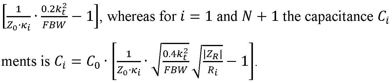
It is evident from mathematical expressions (22) and (25) that the capacitances CL of the pas sive reactive elements is negative unless the desired fractional bandwidth FBW is (very) small. For a wider desired fractional bandwidth FBW , the negative capacitances Ct of the passive reactive elements are converted to inductances Lt according to the following funda mental trade-off relationship:
 and
and

Therefore, for t = 2, ... , N the inductance L t of the passive reactive elements is Lt =— a>s \ZR \
[2 l— , whereas for i = 1 and N + 1 the inductance Lt of the passive reac-
 tive elements

As can be seen from the above mathematical expressions, the inductance of the passive reac tive elements goes down for a larger fractional bandwidth FBW and/or a smaller electro mechanical coupling coefficient k of the AWRs 110-1, ... , 110-N. On the contrary, the in ductance of the first and second matching inductors 160 and 170 goes up for a larger fractional bandwidth FBW and/or a smaller electro-mechanical coupling coefficient k of the AWRs 110-1, ... , 110-N. This can be seen from the following mathematical expression:
 with CS L denoting the capacitance of the first and last inductive elements 160 and 170, and KS L denoting the coupling coefficient of the first and last inductive elements 160 and 170.
As can be seen from the above mathematical expressions, the desired bandwidth of the filter 100 is not limited by the electro-mechanical coupling coefficient k^ . The desired bandwidth of the filter 100 may be adjusted by selecting appropriate capacitance/inductance values for the passive reactive elements 150-1, ... , 150-N+l and the first and second matching inductors 160 and 170.
The high-performance (broad-band) individual resonance frequency of an AWR is typically thickness dependent and multiple frequency operation cannot be integrated. AWR types that are not thickness dependent and can be integrated for multiple frequencies (e.g surface acous tic wave resonators, or contour mode resonators) are limited w.r.t electro-mechanical coupling
coefficient k (e.g. up to only 2%) and thus in filter bandwidth. The proposed filter architec ture provides a topology and formal means to synthesize high-performance integrated AWR filters with substantially broad bandwidth independent of the resonators’ electro-mechanical coupling coefficient k . Moreover, unlike traditional ladder filters with different series and shunt type resonators, the proposed topology may use only a single resonator type (same res onance frequency and input impedance). Further the used AWRs do not require costly trim ming for a high precision resonance frequency. Further, unlike other proposed hybrid tech niques, the proposed topology calls for only one passive reactive component per stage for inter-stage coupling.
In the following, two exemplary filters 200 and 300 comprising capacitive elements and in ductive elements as passive reactive elements are described in connection with Figs. 2 and 3.
Fig. 2 illustrates a filter 200 that is identical to above described filter 100, wherein the passive reactive elements 150-1, ... , 150-N+l are implemented as capacitive elements 250-1, ... , 250- N+l .
The capacitive elements 250-1 and 250-N+l may exhibit a capacitance as given in above mathematical expressions (6) and (25). Speaking more general, the capacitive elements 250- 1 and 250-N+l may exhibit a capacitance proportional to an expression which is mathemati cally correspondent to:
 with aL denoting a constant for the respective capacitive element.
As described above, the coupling coefficient Kt of the respective capacitive element 250-1 or 250-N+l for coupling the first or the last AWR of the cascade of AWRs 110-1, ... , 110-N is proportional to an inverse of a square root of a product of polynomial coefficients of a filter model determining the filter characteristic of the filter 200 (see above mathematical expres sion (3)), wherein one of the polynomial coefficients of the filter model is assigned to the first or the last AWR of the cascade of AWRs 110-1, ... , 110-N.
The capacitive elements 250-2 to 250-N may exhibit a capacitance as given in above mathe matical expressions (6) and (22). Speaking more general, the capacitive elements 250-2 to 250-N may exhibit a capacitance proportional to an expression which is mathematically cor respondent to:
 with a denoting a constant.
As described above, the coupling coefficient KL of the respective capacitive element 250-2 to 250-N for coupling the pair of consecutive AWRs (e.g. AWRs 110-1 and 110-2) is propor tional to an inverse of a square root of a product of polynomial coefficients of a filter model determining the filter characteristic of the filter (see above mathematical expression (3)), wherein the polynomial coefficients of the filter model are assigned to the pair of consecutive AWRs.
Further illustrated in Fig. 2 is a signal source 280 providing an input signal for the filter 200. The signal source 280 is coupled to the input terminal 120 of the filter 200. The signal source 280 is illustrated schematically in Fig. 2 by means of a resistive element 281 representing the resistance Rs of the signal source 280 and a signal generator 282 generating the input signal for the filter 200. For example, the schematic signal source 280 may represent a transmitter, a transceiver or an antenna if the filter 200 is used in a wireless communication application.
Fig. 2 additionally illustrates a load 290 coupled to the output terminal 130 of the filter 200. The load 290 is illustrated schematically in Fig. 2 by means of a resistive element 291 repre senting the resistance RL of the load 290. For example, the schematic load 290 may represent an antenna, a transceiver or a receiver if the filter 200 is used in a wireless communication application.
The filter 200 may enable efficient narrowband filtering, wherein the passband of the filter 200 may be selected
 agnostic.
Fig. 3 illustrates another filter 300 that is identical to above described filter 100, wherein the passive reactive elements 150-1, ... , 150-N+l are implemented as inductive elements 350-1, ... , 350-N+l.
agnostic.
Fig. 3 illustrates another filter 300 that is identical to above described filter 100, wherein the passive reactive elements 150-1, ... , 150-N+l are implemented as inductive elements 350-1, ... , 350-N+l.
The inductive elements 350-1 and 350-N+l may exhibit an inductance as given in above mathematical expressions (9) and (27). Speaking more general, the inductive elements 350-1 and 350-N+l may exhibit an inductance proportional to an expression which is mathemati cally correspondent to:
 with at denoting a constant for the respective inductive element.
As described above, the coupling coefficient Kt of the respective inductive element 350-1 or 350-N+l for coupling the first or the last AWR of the cascade of AWRs 110-1, ... , 110-N is proportional to an inverse of a square root of a product of polynomial coefficients of a filter model determining the filter characteristic of the filter 300 (see above mathematical expres sion (3)), wherein one of the polynomial coefficients of the filter model is assigned to the first or the last AWR of the cascade of AWRs 110-1, ... , 110-N.
The inductive elements 350-2 to 350-N may exhibit an inductance as given in above mathe matical expressions (9) and (26). Speaking more general, the inductive elements 350-2 to 350- N may exhibit a capacitance proportional to an expression which is mathematically corre spondent to: 1
1 Ki-FBwJ (32), with a denoting a constant.
As described above, the coupling coefficient Kt of the respective inductive element 350-2 to 350-N for coupling the pair of consecutive AWRs (e.g. AWRs 110-1 and 110-2) is propor tional to an inverse of a square root of a product of polynomial coefficients of a filter model determining the filter characteristic of the filter 300 (see above mathematical expression (3)),
wherein the polynomial coefficients of the filter model are assigned to the pair of consecutive AWRs.
Similar to what is illustrated in Fig. 2, Fig. 3 further illustrates the signal source 280 coupled to the input terminal 120 of the filter 300 and the load 290 coupled to the output terminal 130 of the filter 300.
The filter 300 may enable efficient wideband filtering, wherein the passband of the filter 300 may be selected
 agnostic.
An exemplary AWR that may be used for an AWR based filter according to one or more aspects of the proposed technique or one or more examples described above is illustrated in Fig. 6. Fig. 6 illustrates a three-terminal (two-port) Contour Mode Resonator (CMR) 600 as an example for an AWR.
The CMR 600 comprises two interleaved interdigitated electrodes 610 and 620. The interdig- itated electrode 610 is coupled to an input terminal 601 for receiving an input signal for the CMR 600. The other interdigitated electrode 610 is coupled to an output terminal 602 for outputting an output signal of the CMR 600. The two interleaved interdigitated electrodes 610 and 620 are arranged on the top (i.e. a first) surface of a suspended piezo-electric film 640. A third (e.g. metal) electrode 630 is arranged on the bottom (i.e. an opposite second) surface of the suspended piezo-electric film 640 as ground plane (i.e. the third electrode is coupled to ground).
The resonance frequency fR of the CMR 600 is determined by the pitch between consecutive fingers of the two interleaved interdigitated electrodes 610 and 620 as indicated in Fig. 6.
Therefore, in some examples, the cascaded AWRs of the proposed filter may be CMRs. How ever, it is to be noted that the proposed AWR based filter is not limited to using CMRs. In general, any type of three-terminal (two-port) AWR may be used. For example, a stacked (two-layer) Film Bulk Acoustic wave Resonator (FBAR) with middle metal layer connected to ground may be used for the cascaded AWRs of the proposed filter.
An example of an implementation using an AWR based filter according to one or more as pects of the proposed technique or one or more examples described above is illustrated in Fig. 7. Fig. 7 schematically illustrates an example of a mobile device 700 (e.g. mobile phone, smartphone, tablet-computer, or laptop) comprising a transceiver 710. The transceiver is cou pled to at least one antenna element 720 of the mobile device. A filter 730 according to ex amples described herein is coupled between the transceiver 710 and the antenna element 720.
The characteristics of the filter 730 may be adapted to a frequency band supported by the transceiver 710 for transmission and/or reception of radio frequency signals. For example, a center frequency of the filter 730 may lie within the frequency band supported by the trans ceiver 710. Similarly, a passband of the filter 730 may at least partially cover the frequency band supported by the transceiver 710.
The mobile device 700 may comprise further elements such as, e.g., an application processor, memory, an audio driver, a camera driver, a touch screen, a display driver, sensors, removable memory, a power management integrated circuit or a smart battery.
To this end, a mobile device enabling broadband front-end filtering may be provided.
The above wireless communication circuits using an AWR based filter according to the pro posed technique or one or more of the examples described above may be configured to operate according to one of the 3rd Generation Partnership Project (3GPP)-standardized mobile com munication networks or systems. The mobile or wireless communication system may corre spond to, for example, a 5GNR, a Long-Term Evolution (LTE), an LTE- Advanced (LTE-A), High Speed Packet Access (HSPA), a Universal Mobile Telecommunication System (UMTS) or a UMTS Terrestrial Radio Access Network (UTRAN), an evolved-UTRAN (e-UTRAN), a Global System for Mobile communication (GSM), an Enhanced Data rates for GSM Evo lution (EDGE) network, or a GSM/EDGE Radio Access Network (GERAN). Alternatively, the wireless communication circuits may be configured to operate according to mobile com munication networks with different standards, for example, a Worldwide Inter-operability for Microwave Access (WIMAX) network IEEE 802.16 or Wireless Local Area Network (WLAN) IEEE 802.11, generally an Orthogonal Frequency Division Multiple Access (OFDMA) network, a Time Division Multiple Access (TDMA) network, a Code Division Multiple Access (CDMA) network, a Wideband-CDMA (WCDMA) network, a Frequency
Division Multiple Access (FDMA) network, a Spatial Division Multiple Access (SDMA) net work, etc.
The examples as described herein may be summarized as follows:
Example 1 is a filter, comprising: a cascade of coupled acoustic wave resonators between an input terminal and an output terminal of the filter, wherein the acoustic wave resonators are three-terminal resonators, and wherein the acoustic wave resonators exhibit the same input impedance; and a plurality of coupling structures each coupled to a respective one of a plu rality of conductive paths, wherein each of the plurality of coupling structures consists of a passive reactive element coupled between ground and the respective conductive path, wherein the plurality of conductive paths couple: pairs of consecutive acoustic wave resonators of the cascade of acoustic wave resonators; the input terminal and the first acoustic wave resonator of the cascade of acoustic wave resonators; and the output terminal and the last acoustic wave resonator of the cascade of acoustic wave resonators.
Example 2 is the filter of example 1, wherein the acoustic wave resonators are acoustic wave MEMS resonators.
Example 3 is the filter of example 1 or example 2, wherein the acoustic wave resonators are contour mode resonators.
Example 4 is the filter of any of examples 1 to 3, wherein one of the three-terminals of each acoustic wave resonator is coupled to ground.
Example 5 is the filter of any of examples 1 to 4, wherein the acoustic wave resonators exhibit the same or different resonance frequencies, and wherein the resonance frequency or the res onance frequencies of the acoustic wave resonators is/are different from a desired center fre quency of the filter.
Example 6 is the filter of any of examples 1 to 5, wherein the passive reactive element is a capacitive element.
Example 7 is the filter of example 6, wherein the capacitive element of one of the plurality of coupling structures that is coupled to a conductive path coupling a pair of consecutive acoustic wave resonators of the cascade of acoustic wave resonators exhibits a capacitance propor tional to an expression which is mathematically correspondent to:
 with a denoting a constant, Kt denoting the coupling coefficient of the capacitive element for coupling the pair of consecutive acoustic wave resonators, k denoting an electro-mechanical coupling coefficient of the acoustic wave resonators, and FBW denoting a desired fractional bandwidth of the filter.
Example 8 is the filter of example 7, wherein the coupling coefficient of the capacitive ele ment for coupling the pair of consecutive acoustic wave resonators is proportional to an in verse of a square root of a product of polynomial coefficients of a filter model determining the filter characteristic of the filter, wherein the polynomial coefficients of the filter model are assigned to the pair of consecutive acoustic wave resonators.
Example 9 is the filter of example 8, wherein the capacitance of the capacitive element is determined by an expression which is mathematically correspondent to:
 with Ci denoting the capacitance of the capacitive element, CQ denoting the electro-static ca pacitance of the acoustic wave resonators, Z0 denoting the desired characteristic impedance of the filter, Kt denoting the coupling coefficient of the capacitive element for coupling the pair of consecutive acoustic wave resonators, k denoting the electro-mechanical coupling coefficient of the acoustic wave resonators, and FBW denoting the desired fractional band width of the filter.
Example 10 is the filter of any of examples 6 to 9, wherein the capacitive element of one of the plurality of coupling structures that is coupled to a conductive path coupling the input terminal and the first acoustic wave resonator of the cascade of acoustic wave resonators or
coupling the output terminal and the last acoustic wave resonator of the cascade of acoustic wave resonators exhibits a capacitance proportional to an expression which is mathematically correspondent to:
 with aL denoting a constant for the capacitive element, KL denoting the coupling coefficient of the capacitive element for coupling the pair of consecutive acoustic wave resonators, k de noting an electro-mechanical coupling coefficient of the acoustic wave resonators, and FBW denoting a desired fractional bandwidth of the filter.
Example 11 is the filter of example 10, wherein the coupling coefficient of the capacitive element for coupling the first or the last acoustic wave resonator of the cascade of acoustic wave resonators is proportional to an inverse of a square root of a product of polynomial coefficients of a filter model determining the filter characteristic of the filter, wherein one of the polynomial coefficients of the filter model is assigned to the first or the last acoustic wave resonator of the cascade of acoustic wave resonators.
Example 12 is the filter of example 11, wherein the capacitance of the capacitive element is determined by an expression which is mathematically correspondent to:
 with Ci denoting the capacitance of the capacitive element, CQ denoting the electro-static ca pacitance of the acoustic wave resonators, Z0 denoting the desired characteristic impedance of the filter, Kt denoting the coupling coefficient of the capacitive element for coupling the first or the last acoustic wave resonator of the cascade of acoustic wave resonators, k denot ing the electro-mechanical coupling coefficient of the acoustic wave resonators, FBW denot ing the desired fractional bandwidth of the filter, ZR denoting the input impedance of the acoustic wave resonators, and Rt denoting a resistance presented to the input node or the output node of the filter by an electric element coupled to the input node or the output node of the filter.
Example 13 is the filter of any of examples 1 to 5, wherein the passive reactive element is an inductive element.
with Ci denoting the capacitance of the capacitive element, CQ denoting the electro-static ca pacitance of the acoustic wave resonators, Z0 denoting the desired characteristic impedance of the filter, Kt denoting the coupling coefficient of the capacitive element for coupling the first or the last acoustic wave resonator of the cascade of acoustic wave resonators, k denot ing the electro-mechanical coupling coefficient of the acoustic wave resonators, FBW denot ing the desired fractional bandwidth of the filter, ZR denoting the input impedance of the acoustic wave resonators, and Rt denoting a resistance presented to the input node or the output node of the filter by an electric element coupled to the input node or the output node of the filter.
Example 13 is the filter of any of examples 1 to 5, wherein the passive reactive element is an inductive element.
Example 14 is the filter of example 13, wherein the inductive element of one of the plurality of coupling structures that is coupled to a conductive path coupling a pair of consecutive acoustic wave resonators of the cascade of acoustic wave resonators exhibits an inductance proportional to an expression which is mathematically correspondent to:
 with a denoting a constant, Kt denoting the coupling coefficient of the capacitive element for coupling the pair of consecutive acoustic wave resonators, k denoting an electro-mechanical coupling coefficient of the acoustic wave resonators, and FBW denoting a desired fractional bandwidth of the filter.
Example 15 is the filter of example 14, wherein the coupling coefficient of the inductive ele ment for coupling the pair of consecutive acoustic wave resonators is proportional to an in verse of a square root of a product of polynomial coefficients of a filter model determining the filter characteristic of the filter, wherein the polynomial coefficients of the filter model are assigned to the pair of consecutive acoustic wave resonators.
Example 16 is the filter of example 15, wherein the inductance of the inductive element is determined by an expression which is mathematically correspondent to:
 with Li denoting the inductance of the inductive element, w5 denoting the angular resonance frequency of the acoustic wave resonators, \ZR | denoting the input impedance of the acoustic wave resonators, Z0 denoting the desired characteristic impedance of the filter, Kt denoting the coupling coefficient of the capacitive element for coupling the pair of consecutive acoustic wave resonators, k denoting the electro-mechanical coupling coefficient of the acoustic wave resonators, and FBW denoting the desired fractional bandwidth of the filter.
Example 17 is the filter of any of examples 13 to 16, wherein the inductive element of one of the plurality of coupling structures that is coupled to a conductive path coupling the input terminal and the first acoustic wave resonator of the cascade of acoustic wave resonators or coupling the output terminal and the last acoustic wave resonator of the cascade of acoustic wave resonators exhibits an inductance proportional to an expression which is mathematically correspondent to:
with Li denoting the inductance of the inductive element, w5 denoting the angular resonance frequency of the acoustic wave resonators, \ZR | denoting the input impedance of the acoustic wave resonators, Z0 denoting the desired characteristic impedance of the filter, Kt denoting the coupling coefficient of the capacitive element for coupling the pair of consecutive acoustic wave resonators, k denoting the electro-mechanical coupling coefficient of the acoustic wave resonators, and FBW denoting the desired fractional bandwidth of the filter.
Example 17 is the filter of any of examples 13 to 16, wherein the inductive element of one of the plurality of coupling structures that is coupled to a conductive path coupling the input terminal and the first acoustic wave resonator of the cascade of acoustic wave resonators or coupling the output terminal and the last acoustic wave resonator of the cascade of acoustic wave resonators exhibits an inductance proportional to an expression which is mathematically correspondent to:
 with aL denoting a constant for the capacitive element, KL denoting the coupling coefficient of the capacitive element for coupling the pair of consecutive acoustic wave resonators,
 de noting an electro-mechanical coupling coefficient of the acoustic wave resonators, and FBW denoting a desired fractional bandwidth of the filter.
Example 18 is the filter of example 17, wherein the coupling coefficient of the inductive ele ment for coupling the first or the last acoustic wave resonator of the cascade of acoustic wave resonators is proportional to an inverse of a square root of a product of polynomial coefficients of a filter model determining the filter characteristic of the filter, wherein one of the polyno mial coefficients of the filter model is assigned to the first or the last acoustic wave resonator of the cascade of acoustic wave resonators.
Example 19 is the filter of example 18, wherein the inductance of the inductive element is determined by an expression which is mathematically correspondent to:
 with Li denoting the inductance of the inductive element, w5 denoting the angular resonance frequency of the acoustic wave resonators, \ZR | denoting the input impedance of the acoustic wave resonators, Z0 denoting the desired characteristic impedance of the filter, Kt denoting the coupling coefficient of the capacitive element for coupling the first or the last acoustic
wave resonator of the cascade of acoustic wave resonators, k2 denoting the electro-mechani cal coupling coefficient of the acoustic wave resonators, FBW denoting the desired fractional bandwidth of the filter, ZR denoting the input impedance of the acoustic wave resonators, and Rt denoting a resistance presented to the input node or the output node of the filter by electric elements coupled to the input node or the output node of the filter.
with Li denoting the inductance of the inductive element, w5 denoting the angular resonance frequency of the acoustic wave resonators, \ZR | denoting the input impedance of the acoustic wave resonators, Z0 denoting the desired characteristic impedance of the filter, Kt denoting the coupling coefficient of the capacitive element for coupling the first or the last acoustic
wave resonator of the cascade of acoustic wave resonators, k2 denoting the electro-mechani cal coupling coefficient of the acoustic wave resonators, FBW denoting the desired fractional bandwidth of the filter, ZR denoting the input impedance of the acoustic wave resonators, and Rt denoting a resistance presented to the input node or the output node of the filter by electric elements coupled to the input node or the output node of the filter.
Example 20 is the filter of any of examples 1 to 19, further comprising: a first inductive ele ment coupled between the input terminal and the first acoustic wave resonator of the cascade of acoustic wave resonators; and a second inductive element coupled between the output ter minal and a last acoustic wave resonator of the cascade of acoustic wave resonators.
Example 21 is the filter of example 20, wherein inductances of the first inductive element and the second inductive element are proportional to an inverse of a square of the desired center frequency of the filter and an inverse of a capacitance of the passive reactive element of the coupling structure coupled to the conductive path coupling the input terminal and the first acoustic wave resonator of the cascade of acoustic wave resonators or coupling the output terminal and a last acoustic wave resonator of the cascade of acoustic wave resonators.
Example 22 is the filter of example 21, wherein the inductances of the first inductive element and the second inductive element are determined by an expression which is mathematically correspondent to:
 with LS L determining the inductances of the first inductive element and the second inductive, fs denoting the desired center frequency of the filter, Ct denoting the capacitance of the pas sive reactive element of the coupling structure coupled to the conductive path coupling the input terminal and the first acoustic wave resonator of the cascade of acoustic wave resonators or coupling the output terminal and a last acoustic wave resonator of the cascade of acoustic wave resonators, and C0 denoting the electro-static capacitance of the acoustic wave resona tors.
Example 23 is the filter of any of examples 1 to 22, wherein the number of acoustic wave resonators is equal to the desired order of the filter.
Example 24 is a mobile device comprising a transceiver coupled to an antenna element, wherein a filter according to any of examples 1 to 23 is coupled between the transceiver and the antenna element.
Example 25 is the mobile device of example 24, wherein a center frequency of the filter lies within a frequency band supported by the transceiver.
The aspects and features mentioned and described together with one or more of the previously detailed examples and figures, may as well be combined with one or more of the other exam ples in order to replace a like feature of the other example or in order to additionally introduce the feature to the other example.
The description and drawings merely illustrate the principles of the disclosure. Furthermore, all examples recited herein are principally intended expressly to be only for illustrative pur poses to aid the reader in understanding the principles of the disclosure and the concepts con tributed by the inventor(s) to furthering the art. All statements herein reciting principles, as pects, and examples of the disclosure, as well as specific examples thereof, are intended to encompass equivalents thereof.
A block diagram may, for instance, illustrate a high-level circuit diagram implementing the principles of the disclosure.
It is to be understood that the disclosure of multiple acts, processes, operations, steps or func tions disclosed in the specification or claims may not be construed as to be within the specific order, unless explicitly or implicitly stated otherwise, for instance for technical reasons. Therefore, the disclosure of multiple acts or functions will not limit these to a particular order unless such acts or functions are not interchangeable for technical reasons. Furthermore, in some examples a single act, function, process, operation or step may include or may be broken into multiple sub-acts, -functions, -processes, -operations or -steps, respectively. Such sub acts may be included and part of the disclosure of this single act unless explicitly excluded.
Furthermore, the following claims are hereby incorporated into the detailed description, where each claim may stand on its own as a separate example. While each claim may stand
on its own as a separate example, it is to be noted that - although a dependent claim may refer in the claims to a specific combination with one or more other claims - other examples may also include a combination of the dependent claim with the subject matter of each other de pendent or independent claim. Such combinations are explicitly proposed herein unless it is stated that a specific combination is not intended. Furthermore, it is intended to include also features of a claim to any other independent claim even if this claim is not directly made dependent to the independent claim.
Claims
1. A filter, comprising: a cascade of coupled acoustic wave resonators between an input terminal and an output ter minal of the filter, wherein the acoustic wave resonators are three-terminal resonators, and wherein the acoustic wave resonators exhibit the same input impedance; and a plurality of coupling structures each coupled to a respective one of a plurality of conductive paths, wherein each of the plurality of coupling structures consists of a passive reactive ele ment coupled between ground and the respective conductive path, wherein the plurality of conductive paths couple: pairs of consecutive acoustic wave resonators of the cascade of acoustic wave resonators; the input terminal and the first acoustic wave resonator of the cascade of acoustic wave reso nators; and the output terminal and the last acoustic wave resonator of the cascade of acoustic wave res onators.
2. The filter of claim 1, wherein the acoustic wave resonators are acoustic wave MEMS resonators.
3. The filter of claim 1, wherein the acoustic wave resonators are contour mode resona tors.
4. The filter of claim 1, wherein one of the three-terminals of each acoustic wave reso nator is coupled to ground.
5. The filter of claim 1, wherein the acoustic wave resonators exhibit the same or differ ent resonance frequencies, and wherein the resonance frequency or the resonance frequencies of the acoustic wave resonators is/are different from a desired center frequency of the filter.
6 The filter of claim 1, wherein the passive reactive element is a capacitive element.
7. The filter of claim 6, wherein the capacitive element of one of the plurality of coupling structures that is coupled to a conductive path coupling a pair of consecutive acoustic wave resonators of the cascade of acoustic wave resonators exhibits a capacitance proportional to an expression which is mathematically correspondent to:
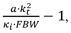 with a denoting a constant, Kt denoting the coupling coefficient of the capacitive element for coupling the pair of consecutive acoustic wave resonators, k denoting an electro-mechanical coupling coefficient of the acoustic wave resonators, and FBW denoting a desired fractional bandwidth of the filter.
8. The filter of claim 7, wherein the coupling coefficient of the capacitive element for coupling the pair of consecutive acoustic wave resonators is proportional to an inverse of a square root of a product of polynomial coefficients of a filter model determining the filter characteristic of the filter, wherein the polynomial coefficients of the filter model are assigned to the pair of consecutive acoustic wave resonators.
9. The filter of claim 8, wherein the capacitance of the capacitive element is determined by an expression which is mathematically correspondent to:
 with Ci denoting the capacitance of the capacitive element, CQ denoting the electro-static ca pacitance of the acoustic wave resonators, Z0 denoting the desired characteristic impedance of the filter, Kt denoting the coupling coefficient of the capacitive element for coupling the pair of consecutive acoustic wave resonators, k denoting the electro-mechanical coupling coefficient of the acoustic wave resonators, and FBW denoting the desired fractional band width of the filter.
10. The filter of claim 6, wherein the capacitive element of one of the plurality of coupling structures that is coupled to a conductive path coupling the input terminal and the first acoustic wave resonator of the cascade of acoustic wave resonators or coupling the output terminal and the last acoustic wave resonator of the cascade of acoustic wave resonators exhibits a capacitance proportional to an expression which is mathematically correspondent to:
with aL denoting a constant for the capacitive element, KL denoting the coupling coefficient of the capacitive element for coupling the pair of consecutive acoustic wave resonators, k de noting an electro-mechanical coupling coefficient of the acoustic wave resonators, and FBW denoting a desired fractional bandwidth of the filter.
11. The filter of claim 10, wherein the coupling coefficient of the capacitive element for coupling the first or the last acoustic wave resonator of the cascade of acoustic wave resona tors is proportional to an inverse of a square root of a product of polynomial coefficients of a filter model determining the filter characteristic of the filter, wherein one of the polynomial coefficients of the filter model is assigned to the first or the last acoustic wave resonator of the cascade of acoustic wave resonators.
12. The filter of claim 11, wherein the capacitance of the capacitive element is determined by an expression which is mathematically correspondent to:
 with Ci denoting the capacitance of the capacitive element, CQ denoting the electro-static ca pacitance of the acoustic wave resonators, Z0 denoting the desired characteristic impedance of the filter, Kt denoting the coupling coefficient of the capacitive element for coupling the first or the last acoustic wave resonator of the cascade of acoustic wave resonators, k denot ing the electro-mechanical coupling coefficient of the acoustic wave resonators, FBW denot ing the desired fractional bandwidth of the filter, ZR denoting the input impedance of the acoustic wave resonators, and Ri denoting a resistance presented to the input node or the output node of the filter by an electric element coupled to the input node or the output node of the filter.
13. The filter of claim 1, wherein the passive reactive element is an inductive element.
14. The filter of claim 13, wherein the inductive element of one of the plurality of coupling structures that is coupled to a conductive path coupling a pair of consecutive acoustic wave resonators of the cascade of acoustic wave resonators exhibits an inductance proportional to an expression which is mathematically correspondent to:
with a denoting a constant, Kt denoting the coupling coefficient of the capacitive element for coupling the pair of consecutive acoustic wave resonators, k denoting an electro-mechanical coupling coefficient of the acoustic wave resonators, and FBW denoting a desired fractional bandwidth of the filter.
15. The filter of claim 14, wherein the coupling coefficient of the inductive element for coupling the pair of consecutive acoustic wave resonators is proportional to an inverse of a square root of a product of polynomial coefficients of a filter model determining the filter characteristic of the filter, wherein the polynomial coefficients of the filter model are assigned to the pair of consecutive acoustic wave resonators.
16. The filter of claim 15, wherein the inductance of the inductive element is determined by an expression which is mathematically correspondent to:
 with Li denoting the inductance of the inductive element, w5 denoting the angular resonance frequency of the acoustic wave resonators, \ZR | denoting the input impedance of the acoustic wave resonators, Z0 denoting the desired characteristic impedance of the filter, Kt denoting the coupling coefficient of the capacitive element for coupling the pair of consecutive acoustic wave resonators, k denoting the electro-mechanical coupling coefficient of the acoustic wave resonators, and FBW denoting the desired fractional bandwidth of the filter.
17. The filter of claim 13 , wherein the inductive element of one of the plurality of coupling structures that is coupled to a conductive path coupling the input terminal and the first acoustic wave resonator of the cascade of acoustic wave resonators or coupling the output terminal and the last acoustic wave resonator of the cascade of acoustic wave resonators exhibits an inductance proportional to an expression which is mathematically correspondent to:
 with aL denoting a constant for the capacitive element, KL denoting the coupling coefficient of the capacitive element for coupling the pair of consecutive acoustic wave resonators, k de noting an electro-mechanical coupling coefficient of the acoustic wave resonators, and FBW denoting a desired fractional bandwidth of the filter.
18. The filter of claim 17, wherein the coupling coefficient of the inductive element for coupling the first or the last acoustic wave resonator of the cascade of acoustic wave resona tors is proportional to an inverse of a square root of a product of polynomial coefficients of a filter model determining the filter characteristic of the filter, wherein one of the polynomial coefficients of the filter model is assigned to the first or the last acoustic wave resonator of the cascade of acoustic wave resonators.
19. The filter of claim 18, wherein the inductance of the inductive element is determined by an expression which is mathematically correspondent to:
 with Li denoting the inductance of the inductive element, w5 denoting the angular resonance frequency of the acoustic wave resonators, \ZR | denoting the input impedance of the acoustic wave resonators, Z0 denoting the desired characteristic impedance of the filter, Kt denoting the coupling coefficient of the capacitive element for coupling the first or the last acoustic wave resonator of the cascade of acoustic wave resonators, k denoting the electro-mechani cal coupling coefficient of the acoustic wave resonators, FBW denoting the desired fractional bandwidth of the filter, ZR denoting the input impedance of the acoustic wave resonators, and Rt denoting a resistance presented to the input node or the output node of the filter by electric elements coupled to the input node or the output node of the filter.
20. The filter of claim 1, further comprising: a first inductive element coupled between the input terminal and the first acoustic wave reso nator of the cascade of acoustic wave resonators; and a second inductive element coupled between the output terminal and a last acoustic wave resonator of the cascade of acoustic wave resonators.
21. The filter of claim 20, wherein inductances of the first inductive element and the sec ond inductive element are proportional to an inverse of a square of the desired center fre quency of the filter and an inverse of a capacitance of the passive reactive element of the coupling structure coupled to the conductive path coupling the input terminal and the first acoustic wave resonator of the cascade of acoustic wave resonators or coupling the output terminal and a last acoustic wave resonator of the cascade of acoustic wave resonators.
22. The filter of claim 21, wherein the inductances of the first inductive element and the second inductive element are determined by an expression which is mathematically corre spondent to:
 with LS L determining the inductances of the first inductive element and the second inductive, fs denoting the desired center frequency of the filter, Ct denoting the capacitance of the pas sive reactive element of the coupling structure coupled to the conductive path coupling the input terminal and the first acoustic wave resonator of the cascade of acoustic wave resonators or coupling the output terminal and a last acoustic wave resonator of the cascade of acoustic wave resonators, and C0 denoting the electro-static capacitance of the acoustic wave resona tors.
23. The filter of claim 1, wherein the number of acoustic wave resonators is equal to the desired order of the filter.
24. A mobile device comprising a transceiver coupled to an antenna element, wherein a filter according to claim 1 is coupled between the transceiver and the antenna element.
25. The mobile device of claim 24, wherein a center frequency of the filter lies within a frequency band supported by the transceiver.
Priority Applications (1)
| Application Number | Priority Date | Filing Date | Title |
|---|---|---|---|
| PCT/US2019/039363 WO2020263254A1 (en) | 2019-06-27 | 2019-06-27 | Wideband filter with cascaded coupled acoustic resonators and shunt reactive elements |
Applications Claiming Priority (1)
| Application Number | Priority Date | Filing Date | Title |
|---|---|---|---|
| PCT/US2019/039363 WO2020263254A1 (en) | 2019-06-27 | 2019-06-27 | Wideband filter with cascaded coupled acoustic resonators and shunt reactive elements |
Publications (1)
| Publication Number | Publication Date |
|---|---|
| WO2020263254A1 true WO2020263254A1 (en) | 2020-12-30 |
Family
ID=67297357
Family Applications (1)
| Application Number | Title | Priority Date | Filing Date |
|---|---|---|---|
| PCT/US2019/039363 Ceased WO2020263254A1 (en) | 2019-06-27 | 2019-06-27 | Wideband filter with cascaded coupled acoustic resonators and shunt reactive elements |
Country Status (1)
| Country | Link |
|---|---|
| WO (1) | WO2020263254A1 (en) |
Cited By (2)
| Publication number | Priority date | Publication date | Assignee | Title |
|---|---|---|---|---|
| CN114221100A (en) * | 2021-12-23 | 2022-03-22 | 中国科学技术大学 | Superconducting band-pass filter |
| CN115378399A (en) * | 2021-05-17 | 2022-11-22 | 诺思(天津)微系统有限责任公司 | Filter module and design method thereof, multiplexer and communication equipment |
Citations (4)
| Publication number | Priority date | Publication date | Assignee | Title |
|---|---|---|---|---|
| AU416264B2 (en) * | 1970-01-15 | 1971-08-16 | Wave filters | |
| US5382930A (en) * | 1992-12-21 | 1995-01-17 | Trw Inc. | Monolithic multipole filters made of thin film stacked crystal filters |
| US20060091978A1 (en) * | 2004-11-03 | 2006-05-04 | Kun Wang | Acoustically coupled thin-film resonators |
| US20130120081A1 (en) * | 2011-11-14 | 2013-05-16 | Qualcomm Mems Technologies, Inc. | Combined resonators and passive circuit components for filter passband flattening |
-
2019
- 2019-06-27 WO PCT/US2019/039363 patent/WO2020263254A1/en not_active Ceased
Patent Citations (4)
| Publication number | Priority date | Publication date | Assignee | Title |
|---|---|---|---|---|
| AU416264B2 (en) * | 1970-01-15 | 1971-08-16 | Wave filters | |
| US5382930A (en) * | 1992-12-21 | 1995-01-17 | Trw Inc. | Monolithic multipole filters made of thin film stacked crystal filters |
| US20060091978A1 (en) * | 2004-11-03 | 2006-05-04 | Kun Wang | Acoustically coupled thin-film resonators |
| US20130120081A1 (en) * | 2011-11-14 | 2013-05-16 | Qualcomm Mems Technologies, Inc. | Combined resonators and passive circuit components for filter passband flattening |
Non-Patent Citations (2)
| Title |
|---|
| MATEESCU I ET AL: "EIGHT-POLE MONOLITHIC FILTERS USING LITHIUM TANTALATE", IEEE PROCEEDINGS OF THE INTERNATIONAL FREQUENCY CONTROL SYMPOSIUM, vol. SYMP. 47, June 1993 (1993-06-01), pages 620 - 625, XP000420180 * |
| VINAY S KULKARNI ET AL: "CONTROL OF ELECTROMECHANICAL COUPLING IN STACKED CRYSTAL FILTERS", IEEE SYSTEMS, APPLICATIONS AND TECHNOLOGY CONFERENCE, May 2006 (2006-05-01), pages 1 - 7, XP031134511 * |
Cited By (2)
| Publication number | Priority date | Publication date | Assignee | Title |
|---|---|---|---|---|
| CN115378399A (en) * | 2021-05-17 | 2022-11-22 | 诺思(天津)微系统有限责任公司 | Filter module and design method thereof, multiplexer and communication equipment |
| CN114221100A (en) * | 2021-12-23 | 2022-03-22 | 中国科学技术大学 | Superconducting band-pass filter |
Similar Documents
| Publication | Publication Date | Title |
|---|---|---|
| CN104412268B (en) | Improved Design of Microwave Acoustic Filter | |
| US12206389B2 (en) | Bandpass filter with improved upper band edge sharpness | |
| EP3506502B1 (en) | Bandpass filter using coupled acoustic resonators | |
| CN109075771B (en) | Radio frequency filter, high selectivity triplexer and communication apparatus | |
| CN107666299B (en) | Method of Designing Acoustic Microwave Filters Based on Frequency Response Requirements | |
| US10873318B2 (en) | Filter circuits having acoustic wave resonators in a transversal configuration | |
| US8576024B2 (en) | Electro-acoustic filter | |
| CN107342749B (en) | Band-pass filter | |
| CN112073018A (en) | Filter, duplexer, multiplexer, and communication apparatus | |
| US20160294357A1 (en) | Variable-frequency filter | |
| JP7313792B2 (en) | Multiplexers, high frequency front-end circuits and communication devices | |
| WO2020168958A1 (en) | Band-pass filter, and duplexer | |
| CN113647016A (en) | Micro-acoustic band-stop filter | |
| WO2020263254A1 (en) | Wideband filter with cascaded coupled acoustic resonators and shunt reactive elements | |
| CN116346069B (en) | Filter and electronic device | |
| US12308824B2 (en) | Resonator circuit using an inverter to adjust anti-resonance frequency | |
| Inaba et al. | A widely tunable filter configuration composed of high q RF resonators and variable capacitors | |
| US11962290B2 (en) | Correction unit for radio frequency filter |
Legal Events
| Date | Code | Title | Description |
|---|---|---|---|
| 121 | Ep: the epo has been informed by wipo that ep was designated in this application |
Ref document number: 19740209 Country of ref document: EP Kind code of ref document: A1 |
|
| NENP | Non-entry into the national phase |
Ref country code: DE |
|
| 122 | Ep: pct application non-entry in european phase |
Ref document number: 19740209 Country of ref document: EP Kind code of ref document: A1 |