WO2020261841A1 - Device and method for controlling an ignition device with a fuel-fed prechamber in an internal combustion engine - Google Patents
Device and method for controlling an ignition device with a fuel-fed prechamber in an internal combustion engine Download PDFInfo
- Publication number
- WO2020261841A1 WO2020261841A1 PCT/JP2020/020786 JP2020020786W WO2020261841A1 WO 2020261841 A1 WO2020261841 A1 WO 2020261841A1 JP 2020020786 W JP2020020786 W JP 2020020786W WO 2020261841 A1 WO2020261841 A1 WO 2020261841A1
- Authority
- WO
- WIPO (PCT)
- Prior art keywords
- prechamber
- characteristic parameter
- combustion chamber
- control unit
- main combustion
- Prior art date
- Legal status (The legal status is an assumption and is not a legal conclusion. Google has not performed a legal analysis and makes no representation as to the accuracy of the status listed.)
- Ceased
Links
Images



Classifications
-
- F—MECHANICAL ENGINEERING; LIGHTING; HEATING; WEAPONS; BLASTING
- F02—COMBUSTION ENGINES; HOT-GAS OR COMBUSTION-PRODUCT ENGINE PLANTS
- F02B—INTERNAL-COMBUSTION PISTON ENGINES; COMBUSTION ENGINES IN GENERAL
- F02B19/00—Engines characterised by precombustion chambers
- F02B19/12—Engines characterised by precombustion chambers with positive ignition
-
- F—MECHANICAL ENGINEERING; LIGHTING; HEATING; WEAPONS; BLASTING
- F02—COMBUSTION ENGINES; HOT-GAS OR COMBUSTION-PRODUCT ENGINE PLANTS
- F02B—INTERNAL-COMBUSTION PISTON ENGINES; COMBUSTION ENGINES IN GENERAL
- F02B19/00—Engines characterised by precombustion chambers
- F02B19/10—Engines characterised by precombustion chambers with fuel introduced partly into pre-combustion chamber, and partly into cylinder
- F02B19/1019—Engines characterised by precombustion chambers with fuel introduced partly into pre-combustion chamber, and partly into cylinder with only one pre-combustion chamber
- F02B19/108—Engines characterised by precombustion chambers with fuel introduced partly into pre-combustion chamber, and partly into cylinder with only one pre-combustion chamber with fuel injection at least into pre-combustion chamber, i.e. injector mounted directly in the pre-combustion chamber
- F02B19/1085—Engines characterised by precombustion chambers with fuel introduced partly into pre-combustion chamber, and partly into cylinder with only one pre-combustion chamber with fuel injection at least into pre-combustion chamber, i.e. injector mounted directly in the pre-combustion chamber controlling fuel injection
-
- F—MECHANICAL ENGINEERING; LIGHTING; HEATING; WEAPONS; BLASTING
- F02—COMBUSTION ENGINES; HOT-GAS OR COMBUSTION-PRODUCT ENGINE PLANTS
- F02D—CONTROLLING COMBUSTION ENGINES
- F02D35/00—Controlling engines, dependent on conditions exterior or interior to engines, not otherwise provided for
- F02D35/02—Controlling engines, dependent on conditions exterior or interior to engines, not otherwise provided for on interior conditions
-
- F—MECHANICAL ENGINEERING; LIGHTING; HEATING; WEAPONS; BLASTING
- F02—COMBUSTION ENGINES; HOT-GAS OR COMBUSTION-PRODUCT ENGINE PLANTS
- F02D—CONTROLLING COMBUSTION ENGINES
- F02D41/00—Electrical control of supply of combustible mixture or its constituents
- F02D41/30—Controlling fuel injection
- F02D41/3094—Controlling fuel injection the fuel injection being effected by at least two different injectors, e.g. one in the intake manifold and one in the cylinder
-
- F—MECHANICAL ENGINEERING; LIGHTING; HEATING; WEAPONS; BLASTING
- F02—COMBUSTION ENGINES; HOT-GAS OR COMBUSTION-PRODUCT ENGINE PLANTS
- F02D—CONTROLLING COMBUSTION ENGINES
- F02D41/00—Electrical control of supply of combustible mixture or its constituents
- F02D41/24—Electrical control of supply of combustible mixture or its constituents characterised by the use of digital means
- F02D41/26—Electrical control of supply of combustible mixture or its constituents characterised by the use of digital means using computer, e.g. microprocessor
- F02D41/28—Interface circuits
- F02D2041/286—Interface circuits comprising means for signal processing
- F02D2041/288—Interface circuits comprising means for signal processing for performing a transformation into the frequency domain, e.g. Fourier transformation
-
- F—MECHANICAL ENGINEERING; LIGHTING; HEATING; WEAPONS; BLASTING
- F02—COMBUSTION ENGINES; HOT-GAS OR COMBUSTION-PRODUCT ENGINE PLANTS
- F02D—CONTROLLING COMBUSTION ENGINES
- F02D35/00—Controlling engines, dependent on conditions exterior or interior to engines, not otherwise provided for
- F02D35/02—Controlling engines, dependent on conditions exterior or interior to engines, not otherwise provided for on interior conditions
- F02D35/023—Controlling engines, dependent on conditions exterior or interior to engines, not otherwise provided for on interior conditions by determining the cylinder pressure
-
- Y—GENERAL TAGGING OF NEW TECHNOLOGICAL DEVELOPMENTS; GENERAL TAGGING OF CROSS-SECTIONAL TECHNOLOGIES SPANNING OVER SEVERAL SECTIONS OF THE IPC; TECHNICAL SUBJECTS COVERED BY FORMER USPC CROSS-REFERENCE ART COLLECTIONS [XRACs] AND DIGESTS
- Y02—TECHNOLOGIES OR APPLICATIONS FOR MITIGATION OR ADAPTATION AGAINST CLIMATE CHANGE
- Y02T—CLIMATE CHANGE MITIGATION TECHNOLOGIES RELATED TO TRANSPORTATION
- Y02T10/00—Road transport of goods or passengers
- Y02T10/10—Internal combustion engine [ICE] based vehicles
- Y02T10/12—Improving ICE efficiencies
-
- Y—GENERAL TAGGING OF NEW TECHNOLOGICAL DEVELOPMENTS; GENERAL TAGGING OF CROSS-SECTIONAL TECHNOLOGIES SPANNING OVER SEVERAL SECTIONS OF THE IPC; TECHNICAL SUBJECTS COVERED BY FORMER USPC CROSS-REFERENCE ART COLLECTIONS [XRACs] AND DIGESTS
- Y02—TECHNOLOGIES OR APPLICATIONS FOR MITIGATION OR ADAPTATION AGAINST CLIMATE CHANGE
- Y02T—CLIMATE CHANGE MITIGATION TECHNOLOGIES RELATED TO TRANSPORTATION
- Y02T10/00—Road transport of goods or passengers
- Y02T10/10—Internal combustion engine [ICE] based vehicles
- Y02T10/40—Engine management systems
Definitions
- the present subject matter relates to a control unit and a method for controlling an ignition device having a fuel-fed prechamber in an internal combustion engine, wherein the control unit controls a jet strength of reactive jets entering from the prechamber into the main combustion chamber
- an ignition device having a fuel-fed prechamber In order to improve the combustion efficiency of an internal combustion engine the use of an ignition device having a fuel-fed prechamber is advantageous.
- the high ignition energy of such an ignition device is provided by a precombustion taking place in the prechamber. This precombustion is initiated by injecting a small amount of fuel into the prechamber and igniting the resulting air-fuel mixture therein. Since the prechamber is connected to the main combustion chamber via small orifices, the combustion inside the prechamber results in reactive jets, which enter from the prechamber into the main combustion chamber and ignite the air-fuel mixture therein. These reactive jets usually expand throughout the entire main combustion chamber and thus provide a plurality of ignition spots which enable a reliable ignition even of very lean air-fuel mixture.
- monitoring the jet strength requires complex and expensive means/devices, in particular, if the monitoring includes identifying a correct value representing the thermal energy included in the jets.
- Patent Literature 1 (EP 3 392 487 A1) describes a control method for a precombustion chamber type gas engine used as an engine for power generation.
- the strength of a torch/reactive jet injected from the precombustion chamber into the main chamber is correlated to a difference or a ratio of the pressure in the prechamber to the pressure in the main chamber. This means that for determining a value representing the torch strength, the pressure in the main chamber as well as the pressure in the prechamber has to be detected.
- pressure sensors for a permanent use in the main combustion chamber are available, equipping a prechamber with a pressure sensor is still a difficult task and leads to significant effort and costs.
- only very small pressure sensors are mountable which are less precise and less durable compared to commonly used pressure sensors.
- an object of the herein described subject matter is to realize a control unit and a method for ensuring a reliable operation of a prechamber ignition under all environmental conditions and over the engine’s lifetime without increasing the complexity of the control unit.
- a control unit for controlling an internal combustion engine may control a jet strength of reactive jets entering from the prechamber into the main combustion chamber.
- the control may be carried out using feedback control.
- a “reactive jet” should be understood as a stream of hot fluid or fluid-like matter that is discharged / blown out / pushed out from the prechamber into the main chamber through orifices in the prechamber wall.
- the hot fluid is preferably a gas produced by a prechamber combustion which may include combustion products such as radicals, carbon monoxide, hydrocarbons.
- a “reactive jet” may also be understood as a (turbulent) flame jet escaping from the prechamber into the main combustion chamber through the orifices.
- the jet strength of the reactive jets may be or may include the ignition energy of the reactive jets.
- ignition energy of the reactive jets For example, as heat energy, kinetic energy and/or chemical energy stored in the combustion products of the prechamber combustion.
- control may include a feedback control of the jet strength, wherein feedback control shall in particular entail the use of a comparison between a target (predefined) parameter representing the jet strength and a real/determined/measured/actual parameter representing the jet strength, and an adaption of at least one parameter affecting the prechamber combustion in order to eliminate a difference between the target (predefined) parameter representing the jet strength and the real/actual parameter representing the jet strength .
- the internal combustion engine (briefly: “combustion engine”, “engine”) may have at least one cylinder, at least one main combustion chamber (briefly: “main chamber”), at least one intake port, at least one main fuel injector, at least one determining means which may detect high-frequency oscillations in the main combustion chamber, and at least one ignition device which may ignite an air-fuel-mixture inside the main combustion chamber.
- the ignition device may comprise a spark plug, a prechamber fuel injector and a prechamber that is connected to the main combustion chamber via at least one orifice in a prechamber wall.
- the control unit may determine the jet strength of the reactive jets by using at least one determining means configured to detect high-frequency oscillations in the main combustion chamber.
- the at least one determining means may be a pressure sensor and/or a knock sensor, and/or a torque sensor.
- High-frequency oscillations may be oscillations having a frequency that is higher than 500 Hz.
- the reactive jets entering the main combustion chamber may induce shock waves spreading throughout the entire main combustion chamber.
- the higher the ignition energy of the reactive jets (previously defined as “jet strength”), the higher the amplitudes of the induced shock waves.
- the shock waves resulting from the entrance of the reactive jets into the main combustion chamber may be used to determine a parameter for representing the jet strength.
- a cylinder pressure sensor as commonly used for controlling the combustion timing in internal combustion engine may be suitable for determining the high-frequency oscillations caused by the jets entering the main combustion chamber. Due to their high natural frequencies, particularly piezoelectric pressure sensors can be used for measuring dynamic pressures and small pressure fluctuations.
- a knock sensor as generally mounted on every gasoline engine for detecting structure-borne noise vibrations due to knocking combustion, can be used to evaluate the oscillations induced by the reactive jets as well.
- the frequencies corresponding to the shock waves induced by the reactive jets are covered by the frequency range of a typical knock sensor but show a different deviation compared to the knocking oscillations.
- a suitable evaluation of the knock sensor signal allows for distinguishing vibrations caused by the reactive jets from vibrations caused by knocking.
- a torque sensor may be used which is, due to its frequency range of, e.g., up to 10 kHz, also able to perform dynamic measures.
- the engine torque may be measured by a torque measuring flange fixed on the engine crank shaft.
- the use of a pressure sensor especially when more than one cylinder is equipped therewith, has the advantage that the jet strength for every cylinder can be adjusted individually and precisely.
- a knock sensor is also able to allocate the detected vibrations to the different cylinders but not as precise as when using an individual pressure sensor per cylinder.
- using a knock sensor is advantageous because it is already available at the engine and therefore it requires only evaluation effort to correctly detect the oscillations caused by the reactive jets.
- the torque oscillations detectable with a torque measuring flange result from the pressure fluctuations of all cylinders and may be sufficient to control the average jet strength.
- control unit may determine a characteristic parameter representing the jet strength of the reactive jets based on the detected high-frequency oscillations in the main combustion chamber. Since the ignition energy of the reactive jets is difficult to determine during engine operation and therefore difficult to access for a feedback control, a “characteristic parameter”, which is based on the detected high-frequency oscillations in the main combustion chamber, may serve as controlled variable and target value for the feedback control.
- the “controlled variable” may be the real/actual characteristic parameter and the target value may be the target (predefined) characteristic parameter.
- the control unit may generate a filtered signal by analyzing the detected high-frequency oscillations in a predefined time range for a predefined number of engine cycles using a bandpass filter that has a predefined frequency band, and may determine the characteristic parameter by identifying a maximum absolute amplitude of the filtered signal for each of the predefined number of engine cycles. Further, it may calculate a mean value of the identified maximum absolute amplitudes, wherein the calculated mean value may be the characteristic parameter.
- the predefined time range may preferably start at 60 deg before firing top dead center (FTDC) and end at 60 deg after FTDC; most preferably, it may start at ignition timing and end at the crank angle of maximum cylinder pressure.
- the bandpass filter may preferably have a frequency range of 1kHz - 20kHz, and most preferably, a frequency range of 4kHz - 10kHz.
- the number of engine cycles to be filtered may preferably be in a range of 50 cycles to 500 cycles, and most preferably, in a range of 100 cycles to 300 cycles.
- control unit may generate a filtered signal by analyzing the detected high-frequency oscillations in a predefined time range for a predefined number of engine cycles using a bandpass filter that has a predefined frequency band, and may determine the characteristic parameter by identifying a peak frequency of the filtered signal for each of the predefined number of engine cycles and calculating a distribution of the identified peak frequencies, wherein the calculated distribution may be the characteristic parameter.
- the predefined time range may preferably start at 60 deg before FTDC and end at 60 deg after FTDC, and most preferably, start at ignition timing and end at the crank angle of maximum cylinder pressure.
- the bandpass filter may preferably have a frequency range of 1kHz - 20kHz, and most preferably, a frequency range of 4kHz - 10kHz.
- the number of engine cycles to be filtered may preferably be in a range of 50 cycles to 500 cycles, and most preferably, in a range of 100 cycles to 300 cycles.
- a frequency analyses may be carried out for each of the predefined number of engine cycles.
- the frequency analyses may preferably be a Fast Fourier Transformation (FFT) cycles.
- FFT Fast Fourier Transformation
- the peak frequency distribution may be calculated by counting the number of engine cycles at an identified peak frequency.
- the frequency deviation may preferably serve as characteristic parameter when a knock sensor is used to detect the high-frequency oscillations in the main combustion chamber.
- the control unit may adjust the jet strength by adapting/controlling a fuel amount to be injected into the prechamber, and/or an injection timing of the prechamber fuel injector.
- the control unit may adjust the jet strength by adapting an injection timing of the main fuel injector and/or an ignition energy provided to the spark plug.
- the jet strength is adjusted based on a difference between a real/actual characteristic parameter and a predetermined target characteristic parameter.
- the real/actual characteristic parameter may be the characteristic parameter calculated/determined based on currently measured engine cycles including high-frequency oscillations.
- the predetermined target characteristic parameter may be calculated in the previously described way during a testing phase of the internal combustion engine and stored in the control unit as characteristic curves or maps.
- the jet strength of the reactive jets can be defined as the ignition energy included in the reactive jets escaping from the prechamber into the main combustion as a result of the combustion which has taken place in the prechamber.
- the heat release of the prechamber combustion creates the ignition energy of the reactive jets.
- the total heat release of a combustion depends on the injected fuel mass and the lower heating value of the fuel. Consequently, the fuel mass contributing to the prechamber combustion may be a suitable parameter to affect the jet strength. Injecting an increased amount of fuel into the prechamber may lead to an increased heat release therein and thus to an increased jet strength. Besides the total heat release of the prechamber combustion, the heat release rate thereof may influence the jet strength.
- the heat release rate may depend on the pressure and temperature conditions inside the prechamber which can be influenced, e.g., by the injection timing of the prechamber fuel injector, injection timing of the main fuel injector and/or an ignition energy provided to the spark plug.
- the injection timing of the prechamber fuel injector injection timing of the main fuel injector and/or an ignition energy provided to the spark plug.
- increasing the electrical ignition energy provided to the spark plug by the ignition coil leads to an increased heat release rate and thus to an increased pressure and temperature rise inside the prechamber. Consequently, increasing the electrical ignition energy provided to the spark plug results in an increased ignition energy of the reactive jets.
- the claimed subject-matter may include an internal combustion engine comprising at least one cylinder, at least one main combustion chamber, at least one intake port, at least one main fuel injector, at least one determining means which may detect high-frequency oscillations in the main combustion chamber, at least one control unit, which may show the technical features as described above, and at least one ignition device which may comprise a spark plug, a prechamber fuel injector and a prechamber that is connected to the main combustion chamber via at least one orifice in a prechamber wall.
- an internal combustion engine comprising at least one cylinder, at least one main combustion chamber, at least one intake port, at least one main fuel injector, at least one determining means which may detect high-frequency oscillations in the main combustion chamber, at least one control unit, which may show the technical features as described above, and at least one ignition device which may comprise a spark plug, a prechamber fuel injector and a prechamber that is connected to the main combustion chamber via at least one orifice in a prechamber wall.
- the claimed subject-matter may include a method for controlling the internal combustion engine as described above, wherein a jet strength of reactive jets entering from the prechamber into the main combustion chamber is controlled by a control unit as described above.
- the jet strength may be represented by a characteristic parameter based on high-frequency oscillations in the main combustion chamber detected by a determining means such as a pressure sensor, a knock sensor and/or a torque sensor.
- the method may generate a filtered signal by analyzing the detected high-frequency oscillations in a predefined time range for a predefined number of engine cycles using a bandpass filter having a predefined frequency band, and may determine the characteristic parameter by identifying a maximum absolute amplitude of the filtered signal for each of the predefined number of engine cycles and calculating a mean value of the identified maximum absolute amplitudes.
- the method may generate the filtered signal by analyzing the detected high-frequency oscillations in a predefined time range for a predefined number of engine cycles using a bandpass filter having a predefined frequency band, and may determine the characteristic parameter by identifying a peak frequency of the filtered signal for each of the predefined number of engine cycles and calculating a distribution of the identified peak frequencies.
- a fuel amount to be injected into the prechamber, and/or an injection timing of the prechamber fuel injector may be adapted based on a difference between an actual characteristic parameter and a predetermined target characteristic parameter.
- an injection timing of a main fuel injector and/or an ignition energy provided to a spark plug (10a) is adapted based on a difference between an actual characteristic parameter and a predetermined target characteristic parameter.
- the claimed subject-matter may include a computer program product storable in a memory comprising instructions which, when carried out by a computer or a computing unit, cause the computer to perform the above described method or aspects thereof, as well as a computer-readable [storage] medium comprising instructions which, when executed by a computer, cause the computer to carry out said method or aspects thereof.
- the herein described subject matter relates to a control unit and a method for controlling an ignition device with a fuel-fed prechamber in an internal combustion engine, wherein the control unit controls a jet strength of reactive jets entering from the prechamber into the main combustion chamber.
- the jet strength may be the ignition energy of the reactive jets which is generated by the prechamber combustion. Since the ignition energy may be difficult to measure during engine operation, pressure oscillations in the main combustion chamber induced by the ignition energy of the reactive jets can be detected instead. Such a measurement may be carried out by a commonly used determining means, such as, e.g., a pressure sensor or a knock sensor.
- a characteristic parameter representing the jet strength may be calculated which is suitable to be used as controlled variable in a feedback control. This leads to a control concept which allows for ensuring the efficiency and the emission limits of the internal combustion engine over its lifetime with lower complexity and high reliability.
- Figure 1 depicts a schematic view of a cylinder of an internal combustion engine comprising an ignition device having a fuel-fed prechamber
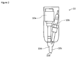
- Figure 2 depicts a schematic view of the ignition device
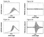
- Figure 3 illustrates examples ( Figures 3a - 3b) of measured cylinder pressure curves when using an ignition device having a conventional spark plug and examples ( Figures 3c - 3d) of measured cylinder pressure curves when using an ignition device having a fuel-fed prechamber
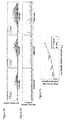
- Figure 4 ( Figures 4a - 4f) exemplifies the influence of increasing the prechamber fuel mass on the filtered cylinder pressure curves
- Figure 5 depicts examples ( Figures 5a - 5b) of filtered cylinder pressure curves and maximum cylinder pressure amplitudes when increasing the fuel amount injected into the prechamber and an example ( Figure 5c) for a correlation between the fuel amount injected into the prechamber and the mean value of maximum cylinder pressure amplitudes captured at a predefined number of cycles
- Figure 6 illustrates an example ( Figure 6
- Figure 1 shows schematically an exemplary cylinder 100 of an otherwise unspecified internal combustion engine, which may have more than one cylinder 100.
- the engine may, for example, have two, three, four, six, eight or less/more cylinders 100.
- the engine comprises at least one piston 2 driven via a connecting rod 3 by a crankshaft (not depicted) for repeated reciprocal movement in the cylinder 100 to define the main combustion chamber therein.
- An (air) intake port 4 with an intake valve 6 as well as an exhaust port 5 with an exhaust valve 7 are connected to the main combustion chamber 1. Ambient air is drawn into the main combustion chamber 1 through the intake port 4. Exhaust gases are discharged from the combustion chamber 1 via the exhaust port 5.
- An ignition device 10 comprising a spark plug 10a, a prechamber fuel injector 10b and a prechamber 10c is attached to the internal combustion engine.
- the spark plug 10a of the ignition device 10 may be electrically connected to an ignition coil (not depicted).
- the spark plug 10a in combination with the ignition coil form the spark ignition device which preferably offers a variable spark duration or multi-spark ignition.
- the internal combustion engine may have one or more ignition device 10. Preferably, it has at least one ignition device(s) 10 per cylinder 100.
- the ignition device 10, or at least parts thereof, is connected to the inside of the main combustion chamber 1 so that reactive jets (depicted in dotted lines) can be introduced therein. Further, the direct fuel injector 8, or at least parts thereof, is attached to the inside of the main combustion chamber 1 for injecting fuel directly into the combustion chamber which leads to an improved efficiency of the engine.
- the direct fuel injector 8 may preferably be an electrohydraulic fuel injector or a piezoelectric fuel injector. Additionally, a port fuel injector 9 is connected to the intake port 4 of the cylinder 100. The high-pressure fuel supply of the direct fuel injector 8 and the high- or low-pressure fuel supply of the port fuel injector 9 are not depicted.
- the main fuel injection may be either performed by the direct main fuel injector 8 or the port main fuel injector 9 or may be divided between both injectors.
- a control unit 11 for controlling the ignition device is further shown in Figure 1.
- the control unit 11 is electrically connected to the ignition device 10, the direct main fuel injector 8 and/or the port main fuel injector 9 and controls the multiple units/injectors/actuators.
- the control unit 11 receives various signals from a plurality of sensors, such as the intake air amount and temperature, the coolant water temperature, the crank angle, the cylinder pressure and the knock signal.
- the control unit 11 may, for example, be the engine control unit (ECU).
- the control unit 11 may also be any other control unit, and signal line connections between the control unit 11 and the controlled units may differ from the example of Figure 1.
- control units 11 may control subgroups of the controlled units, e.g. one control unit 11-1 may control only the ignition device 10, another control unit 11-2 may control only fuel injectors 8, 9 and so on.
- control units 11 may be interconnected with each other hierarchically or in another way.
- the internal combustion engine may be equipped with determining means for detecting high-frequency oscillations in the main combustion chamber 1.
- at least one pressure sensor, at least one knock sensor and/or at least one torque sensor, which are not shown, may be disposed, e.g., in/on the wall of the main combustion chamber 1 and/or on the crank shaft of the engine. Measuring and analyzing the high-pressure oscillations inside the main combustion chamber 1, generated by the prechamber combustion, allows for performing a feedback control regarding the jet strength of the prechamber jets and, therefore, ensuring high efficiency and limited emissions over the lifetime of the engine.
- the prechamber 10c may be equipped with at least one pressure sensor and/or at least one temperature sensor for providing additional information regarding the conditions in the prechamber.
- the ignition device 10 comprises a fuel injector 10a, a spark plug 10b and a prechamber 10c.
- the prechamber 10c is divided off the main combustion chamber 1 by a prechamber wall 10d in which orifices 10e are disposed to introduce the reactive jets generated by the prechamber combustion into the main combustion chamber 1.
- the prechamber 10c may be equipped with at least one pressure sensor and/or at least one temperature sensor for providing additional information regarding the conditions inside the prechamber.
- further components of the ignition device such as the fuel injector 10a, the spark plug 10b or the prechamber wall 10d may be furnished with temperature sensors to achieve additional information about the component behavior of the ignition device 10.
- the shape of the prechamber 10c is not limited to the shape shown in Figure 2 but can be designed in many different shapes, such as hemispherical, conical or cylindrical shapes or combinations thereof. Further, the number, the geometry and the position of the orifices 10e in the prechamber wall 10d are not limited to the example shown in Figure 2.
- the prechamber 10c may comprise a plurality of orifices 10e which are disposed at different positions in the prechamber wall 10d and provided with different diameters.
- the prechamber injector 10a may be connected to the high-pressure fuel supply or the low-pressure fuel supply of the engine (not depicted) or may be connected to a separate fuel supply (not depicted) in order to inject a different fuel as injected into the main combustion chamber 1.
- the spark plug 10b may be electrically connected to an ignition coil (not depicted) which may be included into the ignition device 10 or located at another place of the engine remote to the ignition device 10.
- an ignition coil (not depicted) which may be included into the ignition device 10 or located at another place of the engine remote to the ignition device 10.
- FIGS. 3a - 3d show a comparison of an exemplary cylinder pressure measured in the main combustion chamber 1 at a certain engine operating point using a conventional spark plug (Figs. 3a and 3b) and an ignition device comprising a fuel-fed prechamber (Figs. 3c and 3d), respectively. Comparing the measured cylinder pressure curves in the Figs. 3a and 3c, it becomes obvious that using an ignition device with fuel-fed prechamber narrows the deviations regarding start of combustion and peak cylinder pressure and shortens the combustion duration. This leads to improved combustion stability and increased efficiency. Having a very close look at the cylinder curves depicted in Fig.
- the maximum amplitude of said pressure oscillations can be influenced by the amount of fuel injected into the prechamber 10c.
- Figs. 4a - 4f illustrates bandpass filtered pressure curves, captured at constant load and combustion timing, wherein the fuel amount injected into the prechamber is continuously increased. It becomes obvious that the maximum amplitude of the pressure oscillations increases with increasing fuel amount.
- the increased amount of fuel injected into the prechamber leads to an increased heat release when combusting the mixture therein, and thus to an increased jet strength.
- the fuel mass injected into the prechamber may be a suitable measure to adjust the jet strength of the reactive jets.
- Figs. 5a - 5c demonstrate as to how to process the filtered cylinder pressure curves in order to generate a characteristic parameter which can be correlated to the jet strength. Since the pressure oscillation amplitude is not robust among cycles, one single maximum amplitude is not a representative indicator. Hence, an average value of a predefined number of cycles must be evaluated. Furthermore, the relevant time span for determining a characteristic parameter has to be considered, for example, the time span from ignition timing to the peak pressure location.
- Figs. 5a - 5c results of different processing steps are illustrated in the Figs. 5a - 5c.
- the oscillation curves depicted in Fig. 5a are generated by determining the absolute values of the relating bandpass filtered pressure curves depicted in Figs. 4a, 4c and 4e.
- Fig. 5b To obtain the maximum absolute pressure amplitudes depicted in Fig. 5b, a predefined number of engine cycles is analyzed, to determine the maximum oscillation amplitude of each selected cycle. Subsequently, the mean value of the determined maximum oscillation amplitudes is calculated.
- increasing jet strength caused by increasing prechamber fuel mass, can be identified as an increasing cycle-average of the maximum pressure oscillation amplitude.
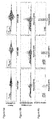
- FIG. 6a - 6c Another method for post processing the recorded cylinder pressure curves, in order to acquire a characteristic parameter representing the jet strength, is depicted in the Figs. 6a - 6c. These figures illustrate results of a FFT analyses carried out on the measured pressure curves.
- Fig. 6a shows the bandpass filtered pressure curves plotted over the measured crank angle
- Fig. 6b shows the latter plotted over the frequency range of the pressure signal. Comparing the measurements performed with increasing prechamber injection mass from m f_PC1 to m f_PC3 , it becomes apparent that the intensity at 7000 kHz increases with increasing prechamber fuel mass. This finding is also confirmed by the frequency deviation depicted in Fig. 6c. It is obvious from Fig. 6c that the relative number of cycles showing a peak at 7000 kHz increases with increasing prechamber fuel mass. Hence, the deviation of the peak frequency may serve as a characteristic parameter to represent the jet strength.
- Figs 7a - 7c show the same procedure as described in connection with the Figs. 5a - 5c, wherein merely the cylinder pressure signal is replaced by a torque sensor signal.
- Fig. 7a the absolute values of bandpass filtered torque curves are depicted.
- Fig. 7b a predefined number of engine cycles is analyzed, to determine the maximum oscillation amplitude of each selected cycle. Subsequently, the mean value of the determined maximum oscillation amplitudes is calculated.
- Figs. 8a - 8c examples for a series of steps to be carried out are depicted to evaluate measuring data from different determining means in order to acquire a characteristic parameter quantifying the jet strength.
- step 100 can be performed, in which the time base of the measured cylinder pressure signal is reduced to the crank angle range from ignition timing to peak firing pressure.
- step S101 the reduced signal is filtered with a bandpass filter, which may, for example, have a frequency range of 4kHz - 10kHz..
- step S102 the maximum amplitude of the filtered signal is determined and stored. This procedure is repeated until the maximum pressure oscillation amplitude is determined for a predefined number of cycles N per operating point. Then, the mean value of the maximum pressure oscillation amplitude is calculated, which is suitable to represents the jet strength of the reactive jets generated by the prechamber combustion.
- Fig. 8b shows an example for an evaluation method using the knock signal which is already available in the control unit and adapted to the relevant time range.
- a suitable bandpass filter S200
- the peak frequency is identified for every engine cycle using FFT analysis and stored in the control unit 11 (S201). This procedure is repeated until a predefined number of engine cycles N have been analyzed. Then the distribution of the peak frequencies is evaluated which allows for characterizing the jet strength by one dominant frequency maximum among cycles.
- step 300 can be executed, in which the time base of the measured torque signal is reduced to a limited crank angle range, here, from ignition timing to peak firing pressure.
- step S301 the reduced signal is filtered with a bandpass filter, which may, for example, have a frequency range of 4kHz - 10kHz.
- step S302 the maximum amplitude of the filtered signal is identified and stored. This procedure is repeated until the maximum torque oscillation amplitude has been determined for a predefined number of cycles N per operating point. Then, the average of the cycle-based amplitude maxima is calculated, which is suitable to represent the jet strength of the prechamber jets averaged over all cylinders.
- the present subject matter offers a control unit and a method for controlling the jet strength of reactive jets entering from the prechamber 10c into the main combustion chamber 1.
- the jet strength can be correlated to detectable pressure oscillations occurring in the main combustion chamber 1 when the jets are escaping the prechamber 10c. According to the detected difference between the real and the target jet strength, the real jet strength can be correctly adjusted. This is carried out by varying parameters influencing the prechamber combustion such as the fuel amount to be injected into the prechamber 10c, the fuel injection timing of said fuel amount and/or the ignition timing.
- Using a feedback control for adapting the precombustion parameters ensures keeping the efficiency and the emission limits of an internal combustion engine over its lifetime.
- main combustion chamber 2 ... piston 3 ... connecting rod 4 ... intake port 5 ... exhaust port 6 ... intake valve 7 ... exhaust valve 8 ... direct main fuel injector 9 ... port main fuel injector 10 ... ignition device 10a ... spark plug 10b ; prechamber fuel injector 10c ... prechamber 10d ... prechamber wall 10e ... orifice 11 ... control unit 100 ... cylinder
Landscapes
- Engineering & Computer Science (AREA)
- Chemical & Material Sciences (AREA)
- Combustion & Propulsion (AREA)
- Mechanical Engineering (AREA)
- General Engineering & Computer Science (AREA)
- Electrical Control Of Air Or Fuel Supplied To Internal-Combustion Engine (AREA)
- Combustion Methods Of Internal-Combustion Engines (AREA)
- Fuel-Injection Apparatus (AREA)
- Combined Controls Of Internal Combustion Engines (AREA)
- Electrical Control Of Ignition Timing (AREA)
Abstract
The present subject matter relates to a control unit and a method for controlling an ignition device with a fuel-fed prechamber in an internal combustion engine, wherein the control unit controls a jet strength of reactive jets entering from the prechamber into the main combustion chamber. The jet strength may be the ignition energy of the reactive jets which is generated by a combustion taking place inside the prechamber. Since the ignition energy may be difficult to measure during engine operation, pressure oscillations in the main combustion chamber induced by the ignition energy of the reactive jets can be detected instead by a commonly used determining means, such as, e.g., a pressure sensor or a knock sensor. Based on the detected pressure oscillations, a characteristic parameter representing the jet strength may be calculated which is suitable to be used as controlled variable in a feedback control. This leads to a control concept which allows for ensuring the efficiency and the emission limits of the internal combustion engine over its lifetime.
Description
The present subject matter relates to a control unit and a method for controlling an ignition device having a fuel-fed prechamber in an internal combustion engine, wherein the control unit controls a jet strength of reactive jets entering from the prechamber into the main combustion chamber
In order to improve the combustion efficiency of an internal combustion engine the use of an ignition device having a fuel-fed prechamber is advantageous. The high ignition energy of such an ignition device is provided by a precombustion taking place in the prechamber. This precombustion is initiated by injecting a small amount of fuel into the prechamber and igniting the resulting air-fuel mixture therein. Since the prechamber is connected to the main combustion chamber via small orifices, the combustion inside the prechamber results in reactive jets, which enter from the prechamber into the main combustion chamber and ignite the air-fuel mixture therein. These reactive jets usually expand throughout the entire main combustion chamber and thus provide a plurality of ignition spots which enable a reliable ignition even of very lean air-fuel mixture.
However, there are some challenges which can reduce the reliability of the prechamber ignition over the lifetime of an internal combustion engine. For example, the use of rich mixtures and high temperatures in the prechamber may lead to coking of the injector tip surface or the prechamber orifices. The deposition of combustion residuals on the injector tip may even lead to a degradation of the injector fuel flow, and thus to a reduced strength of the reactive jets generated by the prechamber combustion. Therefore it would be desirable to enable detecting the jet strength of the reactive jets. This would allow introducing counter measures against a degradation of the injector fuel flow. Furthermore, the jet strength may also be affected by the environmental conditions of the engine. For example, during cold conditions and at low load, the stability of the prechamber combustion is reduced, since the cold prechamber body extracts much energy from the prechamber combustion and the jets. Controlling the jet strength would allow improving the prechamber combustion even under such difficult environmental conditions.
So far, monitoring the jet strength requires complex and expensive means/devices, in particular, if the monitoring includes identifying a correct value representing the thermal energy included in the jets.
Patent Literature 1 (EP 3 392 487 A1) describes a control method for a precombustion chamber type gas engine used as an engine for power generation. The strength of a torch/reactive jet injected from the precombustion chamber into the main chamber is correlated to a difference or a ratio of the pressure in the prechamber to the pressure in the main chamber. This means that for determining a value representing the torch strength, the pressure in the main chamber as well as the pressure in the prechamber has to be detected. Even though pressure sensors for a permanent use in the main combustion chamber are available, equipping a prechamber with a pressure sensor is still a difficult task and leads to significant effort and costs. Moreover, because of the limited space in the prechamber, only very small pressure sensors are mountable which are less precise and less durable compared to commonly used pressure sensors.
In view of the above, an object of the herein described subject matter is to realize a control unit and a method for ensuring a reliable operation of a prechamber ignition under all environmental conditions and over the engine’s lifetime without increasing the complexity of the control unit.
This object is solved by the subject matter according to the independent claims. Further preferred developments are described by the dependent claims.
A control unit for controlling an internal combustion engine may control a jet strength of reactive jets entering from the prechamber into the main combustion chamber. Preferably the control may be carried out using feedback control. Here, a “reactive jet” should be understood as a stream of hot fluid or fluid-like matter that is discharged / blown out / pushed out from the prechamber into the main chamber through orifices in the prechamber wall. The hot fluid is preferably a gas produced by a prechamber combustion which may include combustion products such as radicals, carbon monoxide, hydrocarbons. A “reactive jet” may also be understood as a (turbulent) flame jet escaping from the prechamber into the main combustion chamber through the orifices.
The jet strength of the reactive jets may be or may include the ignition energy of the reactive jets. For example, as heat energy, kinetic energy and/or chemical energy stored in the combustion products of the prechamber combustion.
The term “control” may include a feedback control of the jet strength, wherein feedback control shall in particular entail the use of a comparison between a target (predefined) parameter representing the jet strength and a real/determined/measured/actual parameter representing the jet strength, and an adaption of at least one parameter affecting the prechamber combustion in order to eliminate a difference between the target (predefined) parameter representing the jet strength and the real/actual parameter representing the jet strength .
The internal combustion engine (briefly: “combustion engine”, “engine”) may have at least one cylinder, at least one main combustion chamber (briefly: “main chamber”), at least one intake port, at least one main fuel injector, at least one determining means which may detect high-frequency oscillations in the main combustion chamber, and at least one ignition device which may ignite an air-fuel-mixture inside the main combustion chamber.
The ignition device may comprise a spark plug, a prechamber fuel injector and a prechamber that is connected to the main combustion chamber via at least one orifice in a prechamber wall.
The control unit may determine the jet strength of the reactive jets by using at least one determining means configured to detect high-frequency oscillations in the main combustion chamber. The at least one determining means may be a pressure sensor and/or a knock sensor, and/or a torque sensor. High-frequency oscillations may be oscillations having a frequency that is higher than 500 Hz.
The reactive jets entering the main combustion chamber may induce shock waves spreading throughout the entire main combustion chamber. The higher the ignition energy of the reactive jets (previously defined as “jet strength”), the higher the amplitudes of the induced shock waves. In other words, the shock waves resulting from the entrance of the reactive jets into the main combustion chamber may be used to determine a parameter for representing the jet strength.
The shock waves, induced by the reactive jets escaping rapidly out of the prechamber and expanding throughout the entire main combustion chamber, can be detected as pressure oscillations on the cylinder pressure signal. Hence, a cylinder pressure sensor as commonly used for controlling the combustion timing in internal combustion engine may be suitable for determining the high-frequency oscillations caused by the jets entering the main combustion chamber. Due to their high natural frequencies, particularly piezoelectric pressure sensors can be used for measuring dynamic pressures and small pressure fluctuations. Alternatively or in addition, a knock sensor, as generally mounted on every gasoline engine for detecting structure-borne noise vibrations due to knocking combustion, can be used to evaluate the oscillations induced by the reactive jets as well.
According to the findings of the inventors, the frequencies corresponding to the shock waves induced by the reactive jets are covered by the frequency range of a typical knock sensor but show a different deviation compared to the knocking oscillations.
Hence, a suitable evaluation of the knock sensor signal allows for distinguishing vibrations caused by the reactive jets from vibrations caused by knocking. Alternatively or additionally, a torque sensor may be used which is, due to its frequency range of, e.g., up to 10 kHz, also able to perform dynamic measures. For example, the engine torque may be measured by a torque measuring flange fixed on the engine crank shaft.
Comparing the different determining means, the use of a pressure sensor, especially when more than one cylinder is equipped therewith, has the advantage that the jet strength for every cylinder can be adjusted individually and precisely. A knock sensor is also able to allocate the detected vibrations to the different cylinders but not as precise as when using an individual pressure sensor per cylinder. However, using a knock sensor is advantageous because it is already available at the engine and therefore it requires only evaluation effort to correctly detect the oscillations caused by the reactive jets. The torque oscillations detectable with a torque measuring flange result from the pressure fluctuations of all cylinders and may be sufficient to control the average jet strength.
Furthermore, the control unit may determine a characteristic parameter representing the jet strength of the reactive jets based on the detected high-frequency oscillations in the main combustion chamber. Since the ignition energy of the reactive jets is difficult to determine during engine operation and therefore difficult to access for a feedback control, a “characteristic parameter”, which is based on the detected high-frequency oscillations in the main combustion chamber, may serve as controlled variable and target value for the feedback control. Here, the “controlled variable” may be the real/actual characteristic parameter and the target value may be the target (predefined) characteristic parameter.
To determine/evaluate/calculate the characteristic parameter, the control unit may generate a filtered signal by analyzing the detected high-frequency oscillations in a predefined time range for a predefined number of engine cycles using a bandpass filter that has a predefined frequency band, and may determine the characteristic parameter by identifying a maximum absolute amplitude of the filtered signal for each of the predefined number of engine cycles. Further, it may calculate a mean value of the identified maximum absolute amplitudes, wherein the calculated mean value may be the characteristic parameter.
The predefined time range may preferably start at 60 deg before firing top dead center (FTDC) and end at 60 deg after FTDC; most preferably, it may start at ignition timing and end at the crank angle of maximum cylinder pressure. The bandpass filter may preferably have a frequency range of 1kHz - 20kHz, and most preferably, a frequency range of 4kHz - 10kHz. The number of engine cycles to be filtered may preferably be in a range of 50 cycles to 500 cycles, and most preferably, in a range of 100 cycles to 300 cycles.
Alternatively or additionally, the control unit may generate a filtered signal by analyzing the detected high-frequency oscillations in a predefined time range for a predefined number of engine cycles using a bandpass filter that has a predefined frequency band, and may determine the characteristic parameter by identifying a peak frequency of the filtered signal for each of the predefined number of engine cycles and calculating a distribution of the identified peak frequencies, wherein the calculated distribution may be the characteristic parameter.
The predefined time range may preferably start at 60 deg before FTDC and end at 60 deg after FTDC, and most preferably, start at ignition timing and end at the crank angle of maximum cylinder pressure. The bandpass filter may preferably have a frequency range of 1kHz - 20kHz, and most preferably, a frequency range of 4kHz - 10kHz. The number of engine cycles to be filtered may preferably be in a range of 50 cycles to 500 cycles, and most preferably, in a range of 100 cycles to 300 cycles.
To identify the peak frequency of the filtered signal of each engine cycle, which may be the frequency having the highest intensity, a frequency analyses may be carried out for each of the predefined number of engine cycles. The frequency analyses may preferably be a Fast Fourier Transformation (FFT) cycles. The peak frequency distribution may be calculated by counting the number of engine cycles at an identified peak frequency. The frequency deviation may preferably serve as characteristic parameter when a knock sensor is used to detect the high-frequency oscillations in the main combustion chamber.
The control unit may adjust the jet strength by adapting/controlling a fuel amount to be injected into the prechamber, and/or an injection timing of the prechamber fuel injector. Alternatively or additionally, the control unit may adjust the jet strength by adapting an injection timing of the main fuel injector and/or an ignition energy provided to the spark plug. In this context, the jet strength is adjusted based on a difference between a real/actual characteristic parameter and a predetermined target characteristic parameter. Here, the real/actual characteristic parameter may be the characteristic parameter calculated/determined based on currently measured engine cycles including high-frequency oscillations. In order to calculate the real/actual characteristic parameter with sufficient accuracy, a predefined number of engine cycles must be recorded to calculate the mean value of the identified maximum absolute amplitudes and/or the peak frequency distribution (see previously defined range for the number of engines cycles). The predetermined target characteristic parameter may be calculated in the previously described way during a testing phase of the internal combustion engine and stored in the control unit as characteristic curves or maps.
As described above, the jet strength of the reactive jets can be defined as the ignition energy included in the reactive jets escaping from the prechamber into the main combustion as a result of the combustion which has taken place in the prechamber. In other words, the heat release of the prechamber combustion creates the ignition energy of the reactive jets. In general, the total heat release of a combustion depends on the injected fuel mass and the lower heating value of the fuel. Consequently, the fuel mass contributing to the prechamber combustion may be a suitable parameter to affect the jet strength. Injecting an increased amount of fuel into the prechamber may lead to an increased heat release therein and thus to an increased jet strength. Besides the total heat release of the prechamber combustion, the heat release rate thereof may influence the jet strength. The heat release rate may depend on the pressure and temperature conditions inside the prechamber which can be influenced, e.g., by the injection timing of the prechamber fuel injector, injection timing of the main fuel injector and/or an ignition energy provided to the spark plug. For example, increasing the electrical ignition energy provided to the spark plug by the ignition coil leads to an increased heat release rate and thus to an increased pressure and temperature rise inside the prechamber. Consequently, increasing the electrical ignition energy provided to the spark plug results in an increased ignition energy of the reactive jets.
Further, the claimed subject-matter may include an internal combustion engine comprising at least one cylinder, at least one main combustion chamber, at least one intake port, at least one main fuel injector, at least one determining means which may detect high-frequency oscillations in the main combustion chamber, at least one control unit, which may show the technical features as described above, and at least one ignition device which may comprise a spark plug, a prechamber fuel injector and a prechamber that is connected to the main combustion chamber via at least one orifice in a prechamber wall.
Furthermore, the claimed subject-matter may include a method for controlling the internal combustion engine as described above, wherein a jet strength of reactive jets entering from the prechamber into the main combustion chamber is controlled by a control unit as described above.
The jet strength may be represented by a characteristic parameter based on high-frequency oscillations in the main combustion chamber detected by a determining means such as a pressure sensor, a knock sensor and/or a torque sensor.
The method may generate a filtered signal by analyzing the detected high-frequency oscillations in a predefined time range for a predefined number of engine cycles using a bandpass filter having a predefined frequency band, and may determine the characteristic parameter by identifying a maximum absolute amplitude of the filtered signal for each of the predefined number of engine cycles and calculating a mean value of the identified maximum absolute amplitudes.
Alternatively or additionally, the method may generate the filtered signal by analyzing the detected high-frequency oscillations in a predefined time range for a predefined number of engine cycles using a bandpass filter having a predefined frequency band, and may determine the characteristic parameter by identifying a peak frequency of the filtered signal for each of the predefined number of engine cycles and calculating a distribution of the identified peak frequencies.
Subsequently, a fuel amount to be injected into the prechamber, and/or an injection timing of the prechamber fuel injector may be adapted based on a difference between an actual characteristic parameter and a predetermined target characteristic parameter.
Alternatively or additionally, an injection timing of a main fuel injector and/or an ignition energy provided to a spark plug (10a) is adapted based on a difference between an actual characteristic parameter and a predetermined target characteristic parameter.
Further, the claimed subject-matter may include a computer program product storable in a memory comprising instructions which, when carried out by a computer or a computing unit, cause the computer to perform the above described method or aspects thereof, as well as a computer-readable [storage] medium comprising instructions which, when executed by a computer, cause the computer to carry out said method or aspects thereof.
Summarizing, the herein described subject matter relates to a control unit and a method for controlling an ignition device with a fuel-fed prechamber in an internal combustion engine, wherein the control unit controls a jet strength of reactive jets entering from the prechamber into the main combustion chamber. The jet strength may be the ignition energy of the reactive jets which is generated by the prechamber combustion. Since the ignition energy may be difficult to measure during engine operation, pressure oscillations in the main combustion chamber induced by the ignition energy of the reactive jets can be detected instead. Such a measurement may be carried out by a commonly used determining means, such as, e.g., a pressure sensor or a knock sensor. Based on the detected pressure oscillations, a characteristic parameter representing the jet strength may be calculated which is suitable to be used as controlled variable in a feedback control. This leads to a control concept which allows for ensuring the efficiency and the emission limits of the internal combustion engine over its lifetime with lower complexity and high reliability.
In the following the claimed subject-matter will be further explained based on at least one preferential example with reference to the attached exemplary and schematic drawings, wherein:
Figure 1 shows schematically an exemplary cylinder 100 of an otherwise unspecified internal combustion engine, which may have more than one cylinder 100. The engine may, for example, have two, three, four, six, eight or less/more cylinders 100. The engine comprises at least one piston 2 driven via a connecting rod 3 by a crankshaft (not depicted) for repeated reciprocal movement in the cylinder 100 to define the main combustion chamber therein.
An (air) intake port 4 with an intake valve 6 as well as an exhaust port 5 with an exhaust valve 7 are connected to the main combustion chamber 1. Ambient air is drawn into the main combustion chamber 1 through the intake port 4. Exhaust gases are discharged from the combustion chamber 1 via the exhaust port 5. An ignition device 10 comprising a spark plug 10a, a prechamber fuel injector 10b and a prechamber 10c is attached to the internal combustion engine.
The spark plug 10a of the ignition device 10 may be electrically connected to an ignition coil (not depicted). The spark plug 10a in combination with the ignition coil form the spark ignition device which preferably offers a variable spark duration or multi-spark ignition. The internal combustion engine may have one or more ignition device 10. Preferably, it has at least one ignition device(s) 10 per cylinder 100. The ignition device 10, or at least parts thereof, is connected to the inside of the main combustion chamber 1 so that reactive jets (depicted in dotted lines) can be introduced therein. Further, the direct fuel injector 8, or at least parts thereof, is attached to the inside of the main combustion chamber 1 for injecting fuel directly into the combustion chamber which leads to an improved efficiency of the engine. The direct fuel injector 8 may preferably be an electrohydraulic fuel injector or a piezoelectric fuel injector. Additionally, a port fuel injector 9 is connected to the intake port 4 of the cylinder 100. The high-pressure fuel supply of the direct fuel injector 8 and the high- or low-pressure fuel supply of the port fuel injector 9 are not depicted. The main fuel injection may be either performed by the direct main fuel injector 8 or the port main fuel injector 9 or may be divided between both injectors.
A control unit 11 for controlling the ignition device is further shown in Figure 1. The control unit 11 is electrically connected to the ignition device 10, the direct main fuel injector 8 and/or the port main fuel injector 9 and controls the multiple units/injectors/actuators. In this context, the control unit 11 receives various signals from a plurality of sensors, such as the intake air amount and temperature, the coolant water temperature, the crank angle, the cylinder pressure and the knock signal. The control unit 11 may, for example, be the engine control unit (ECU).
The control unit 11 may also be any other control unit, and signal line connections between the control unit 11 and the controlled units may differ from the example of Figure 1. For example, there may be a plurality of control units 11 which may control subgroups of the controlled units, e.g. one control unit 11-1 may control only the ignition device 10, another control unit 11-2 may control only fuel injectors 8, 9 and so on. Even further, if there is a plurality of control units 11, these control units 11 may be interconnected with each other hierarchically or in another way. Alternatively, there may be one single control unit 11 which includes all the control functions of the multiple actuators.
Further, the internal combustion engine may be equipped with determining means for detecting high-frequency oscillations in the main combustion chamber 1. For example, at least one pressure sensor, at least one knock sensor and/or at least one torque sensor, which are not shown, may be disposed, e.g., in/on the wall of the main combustion chamber 1 and/or on the crank shaft of the engine. Measuring and analyzing the high-pressure oscillations inside the main combustion chamber 1, generated by the prechamber combustion, allows for performing a feedback control regarding the jet strength of the prechamber jets and, therefore, ensuring high efficiency and limited emissions over the lifetime of the engine.
Furthermore, the prechamber 10c may be equipped with at least one pressure sensor and/or at least one temperature sensor for providing additional information regarding the conditions in the prechamber.
In Figure 2 a schematic view of the ignition device 10 is depicted. The ignition device 10 comprises a fuel injector 10a, a spark plug 10b and a prechamber 10c. The prechamber 10c is divided off the main combustion chamber 1 by a prechamber wall 10d in which orifices 10e are disposed to introduce the reactive jets generated by the prechamber combustion into the main combustion chamber 1. Furthermore, the prechamber 10c may be equipped with at least one pressure sensor and/or at least one temperature sensor for providing additional information regarding the conditions inside the prechamber. Alternatively or in addition, further components of the ignition device, such as the fuel injector 10a, the spark plug 10b or the prechamber wall 10d may be furnished with temperature sensors to achieve additional information about the component behavior of the ignition device 10.
The shape of the prechamber 10c is not limited to the shape shown in Figure 2 but can be designed in many different shapes, such as hemispherical, conical or cylindrical shapes or combinations thereof. Further, the number, the geometry and the position of the orifices 10e in the prechamber wall 10d are not limited to the example shown in Figure 2. The prechamber 10c may comprise a plurality of orifices 10e which are disposed at different positions in the prechamber wall 10d and provided with different diameters. The prechamber injector 10a may be connected to the high-pressure fuel supply or the low-pressure fuel supply of the engine (not depicted) or may be connected to a separate fuel supply (not depicted) in order to inject a different fuel as injected into the main combustion chamber 1. The spark plug 10b may be electrically connected to an ignition coil (not depicted) which may be included into the ignition device 10 or located at another place of the engine remote to the ignition device 10. Preferably, there may be one ignition coil for each ignition device 10 but a single ignition coil for multiple ignition devices 10 may also be possible.
The Figures 3a - 3d show a comparison of an exemplary cylinder pressure measured in the main combustion chamber 1 at a certain engine operating point using a conventional spark plug (Figs. 3a and 3b) and an ignition device comprising a fuel-fed prechamber (Figs. 3c and 3d), respectively. Comparing the measured cylinder pressure curves in the Figs. 3a and 3c, it becomes obvious that using an ignition device with fuel-fed prechamber narrows the deviations regarding start of combustion and peak cylinder pressure and shortens the combustion duration. This leads to improved combustion stability and increased efficiency. Having a very close look at the cylinder curves depicted in Fig. 3c, oscillations are discernable on single pressure curves, which become visible when filtering a representative part of the measured pressure signal, e.g., by a high-pass filter (see Fig. 3d). In the present example, the crank angle region between 60 deg b. FDTC and 60 deg a. FTDC is cut out the measured pressure signal and filtered by a bandpass filter having a frequency range of 4kHz - 10kHz. Whereas the filtered pressure signal depicted in Fig. 3b, which was captured when using a conventional spark plug, does not show significant pressure oscillations at the recorded operating point, the corresponding signal when using a prechamber ignition exhibits strong oscillations with high amplitudes. Such distinct oscillation amplitudes are only experienced for spark ignition in case of knocking. However, the pressure oscillations shown in Fig. 3d are not induced by knocking but by the reactive jets escaping rapidly through the orifices 10e of the prechamber 10c and thus generating shock waves inside the main combustion chamber 1.
As visible in the Figs. 4a - 4f, the maximum amplitude of said pressure oscillations can be influenced by the amount of fuel injected into the prechamber 10c. Figs. 4a - 4f illustrates bandpass filtered pressure curves, captured at constant load and combustion timing, wherein the fuel amount injected into the prechamber is continuously increased. It becomes obvious that the maximum amplitude of the pressure oscillations increases with increasing fuel amount. The increased amount of fuel injected into the prechamber leads to an increased heat release when combusting the mixture therein, and thus to an increased jet strength. Hence, as mentioned above, the fuel mass injected into the prechamber may be a suitable measure to adjust the jet strength of the reactive jets.
Figs. 5a - 5c demonstrate as to how to process the filtered cylinder pressure curves in order to generate a characteristic parameter which can be correlated to the jet strength. Since the pressure oscillation amplitude is not robust among cycles, one single maximum amplitude is not a representative indicator. Hence, an average value of a predefined number of cycles must be evaluated. Furthermore, the relevant time span for determining a characteristic parameter has to be considered, for example, the time span from ignition timing to the peak pressure location.
In view of the above, results of different processing steps are illustrated in the Figs. 5a - 5c. The oscillation curves depicted in Fig. 5a are generated by determining the absolute values of the relating bandpass filtered pressure curves depicted in Figs. 4a, 4c and 4e. To obtain the maximum absolute pressure amplitudes depicted in Fig. 5b, a predefined number of engine cycles is analyzed, to determine the maximum oscillation amplitude of each selected cycle. Subsequently, the mean value of the determined maximum oscillation amplitudes is calculated. As clearly derivable from Fig. 5c. increasing jet strength, caused by increasing prechamber fuel mass, can be identified as an increasing cycle-average of the maximum pressure oscillation amplitude.
Another method for post processing the recorded cylinder pressure curves, in order to acquire a characteristic parameter representing the jet strength, is depicted in the Figs. 6a - 6c. These figures illustrate results of a FFT analyses carried out on the measured pressure curves.
While Fig. 6a shows the bandpass filtered pressure curves plotted over the measured crank angle, Fig. 6b shows the latter plotted over the frequency range of the pressure signal. Comparing the measurements performed with increasing prechamber injection mass from mf_PC1 to mf_PC3, it becomes apparent that the intensity at 7000 kHz increases with increasing prechamber fuel mass. This finding is also confirmed by the frequency deviation depicted in Fig. 6c. It is obvious from Fig. 6c that the relative number of cycles showing a peak at 7000 kHz increases with increasing prechamber fuel mass. Hence, the deviation of the peak frequency may serve as a characteristic parameter to represent the jet strength.
Figs 7a - 7c show the same procedure as described in connection with the Figs. 5a - 5c, wherein merely the cylinder pressure signal is replaced by a torque sensor signal. In Fig. 7a the absolute values of bandpass filtered torque curves are depicted. To obtain the maximum absolute torque amplitudes depicted in Fig. 7b, a predefined number of engine cycles is analyzed, to determine the maximum oscillation amplitude of each selected cycle. Subsequently, the mean value of the determined maximum oscillation amplitudes is calculated.
Similar to Fig. 5c, it is also obvious from Fig. 7c that increasing jet strength, caused by increasing prechamber fuel mass, can be identified as an increasing cycle-average of the maximum torque oscillation amplitude. This means that a torque measurement is equally suitable to detect the jet strength of the reactive jets generated by the prechamber combustion as a cylinder pressure measurement. However, the torque oscillations detectable with a torque measuring flange result from the pressure fluctuations of all cylinders and therefore may only be sufficient to control the average jet strength. In contrast, evaluating the pressure signal of every cylinder allows for correcting the jet strength individually
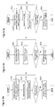
In the Figs. 8a - 8c examples for a series of steps to be carried out are depicted to evaluate measuring data from different determining means in order to acquire a characteristic parameter quantifying the jet strength.
In Fig. 8a an example for an evaluation method using a cylinder pressure signal is depicted. To carry out the method steps S100 to S103, a predefined number of cycle-based cylinder pressure curves must be recorded per engine operating point. Having captured at least one cycle, step 100 can be performed, in which the time base of the measured cylinder pressure signal is reduced to the crank angle range from ignition timing to peak firing pressure. Afterwards, in step S101 the reduced signal is filtered with a bandpass filter, which may, for example, have a frequency range of 4kHz - 10kHz.. In step S102 the maximum amplitude of the filtered signal is determined and stored. This procedure is repeated until the maximum pressure oscillation amplitude is determined for a predefined number of cycles N per operating point. Then, the mean value of the maximum pressure oscillation amplitude is calculated, which is suitable to represents the jet strength of the reactive jets generated by the prechamber combustion.
Further, Fig. 8b shows an example for an evaluation method using the knock signal which is already available in the control unit and adapted to the relevant time range. After applying a suitable bandpass filter (S200) the peak frequency is identified for every engine cycle using FFT analysis and stored in the control unit 11 (S201). This procedure is repeated until a predefined number of engine cycles N have been analyzed. Then the distribution of the peak frequencies is evaluated which allows for characterizing the jet strength by one dominant frequency maximum among cycles.
In Fig. 8c a similar procedure as for the post processing of the pressure sensor signal is described except that a torque sensor is used instead of a pressure sensor. After recording the cycle-based torque signal for at least one engine cycle, step 300 can be executed, in which the time base of the measured torque signal is reduced to a limited crank angle range, here, from ignition timing to peak firing pressure. Afterwards, in step S301 the reduced signal is filtered with a bandpass filter, which may, for example, have a frequency range of 4kHz - 10kHz. In step S302 the maximum amplitude of the filtered signal is identified and stored. This procedure is repeated until the maximum torque oscillation amplitude has been determined for a predefined number of cycles N per operating point. Then, the average of the cycle-based amplitude maxima is calculated, which is suitable to represent the jet strength of the prechamber jets averaged over all cylinders.
Again summarizing, the present subject matter offers a control unit and a method for controlling the jet strength of reactive jets entering from the prechamber 10c into the main combustion chamber 1. The jet strength can be correlated to detectable pressure oscillations occurring in the main combustion chamber 1 when the jets are escaping the prechamber 10c. According to the detected difference between the real and the target jet strength, the real jet strength can be correctly adjusted. This is carried out by varying parameters influencing the prechamber combustion such as the fuel amount to be injected into the prechamber 10c, the fuel injection timing of said fuel amount and/or the ignition timing. Using a feedback control for adapting the precombustion parameters ensures keeping the efficiency and the emission limits of an internal combustion engine over its lifetime.
1 ... main combustion chamber
2 ... piston
3 ... connecting rod
4 ... intake port
5 ... exhaust port
6 ... intake valve
7 ... exhaust valve
8 ... direct main fuel injector
9 ... port main fuel injector
10 ... ignition device
10a ... spark plug
10b ... prechamber fuel injector
10c ... prechamber
10d ... prechamber wall
10e ... orifice
11 ... control unit
100 ... cylinder
Claims (15)
- Control unit (11) for controlling an internal combustion engine having at least one cylinder (100), at least one main combustion chamber (1), at least one intake port (4), at least one main fuel injector (8, 9), at least one determining means configured to detect high-frequency oscillations in the main combustion chamber (1), and at least one ignition device (10) configured to ignite an air-fuel-mixture inside the main combustion chamber (1),
wherein the ignition device (10) comprises a spark plug (10a), a prechamber fuel injector (10b) and a prechamber (10c) connected to the main combustion chamber (1) via at least one orifice (10e) in a prechamber wall (10d), and
wherein the control unit (11) is configured to control a jet strength of reactive jets entering from the prechamber (10c) into the main combustion chamber (1). - Control unit (11) according to claim 1, wherein the at least one determining means is a pressure sensor, a knock sensor, and/or a torque sensor.
- Control unit (11) according to at least one of the preceding claims 1 to 2 configured to determine a characteristic parameter representing the jet strength based on the detected high-frequency oscillations in the main combustion chamber.
- Control unit (11) according to at least one of the preceding claims 1 to 3 configured
- to generate a filtered signal by analyzing the detected high-frequency oscillations in a predefined time range for a predefined number of engine cycles using a bandpass filter that has a predefined frequency band, and
- to determine the characteristic parameter by identifying a maximum absolute amplitude of the filtered signal for each of the predefined number of engine cycles and by calculating a mean value of the identified maximum absolute amplitudes, wherein the calculated mean value is the characteristic parameter. - Control unit (11) according to at least one of the preceding claims 1 to 4 configured
- to generate a filtered signal by analyzing the detected high-frequency oscillations in a predefined time range for a predefined number of engine cycles using a bandpass filter that has a predefined frequency band, and
- to determine the characteristic parameter by identifying a peak frequency of the filtered signal for each of the predefined number of engine cycles and calculating a distribution of the identified peak frequencies, wherein the calculated distribution is the characteristic parameter. - Control unit (11) according to at least one of the preceding claims 1 to 5 configured to adjust the jet strength by adapting a fuel amount to be injected into the prechamber, and/or an injection timing of the prechamber fuel injector (10b), wherein the jet strength is adjusted based on a difference between an actual characteristic parameter and a predetermined target characteristic parameter.
- Control unit (11) according to at least one of the preceding claims 1 to 6 configured to adjust the jet strength by adapting an injection timing of the main fuel injector (8, 9), and/or an ignition energy provided to the spark plug (10a), wherein the jet strength is adjusted based on a difference between an actual characteristic parameter and a predetermined target characteristic parameter.
- Internal combustion engine comprising at least one cylinder (100), at least one main combustion chamber (1), at least one intake port (4), at least one main fuel injector (8, 9), at least one determining means configured to detect high-frequency oscillations in the main combustion chamber (1),
at least one control unit (11) according to at least one of the preceding claims 1 to 7, and at least one ignition device (10) configured to ignite an air-fuel-mixture inside the main combustion chamber (1),
wherein the ignition device (10) comprises a spark plug (10a), a prechamber fuel injector (10b) and a prechamber (10c) that is connected to the main combustion chamber (1) via at least one orifice (10e) in a prechamber wall (10d). - Method for controlling an internal combustion engine according to claim 8, wherein a jet strength of reactive jets entering from the prechamber (10c) into the main combustion chamber (1) is controlled by a control unit (11) according to at least one of the preceding claims 1 to 7.
- Method according to claim 9, wherein the jet strength is represented by a characteristic parameter based on the detected high-frequency oscillations in the main combustion chamber.
- Method according to at least one of the preceding claims 9 to 10, wherein a filtered signal is generated by analyzing the detected high-frequency oscillations in a predefined time range for a predefined number of engine cycles using a bandpass filter having a predefined frequency band,
and wherein the characteristic parameter is determined by identifying a maximum absolute amplitude of the filtered signal for each of the predefined number of engine cycles and calculating a mean value of the identified maximum absolute amplitudes. - Method according to at least one of the preceding claims 9 to 11, wherein a filtered signal is generated by analyzing the detected high-frequency oscillations in a predefined time range for a predefined number of engine cycles using a bandpass filter having a predefined frequency band,
and wherein the characteristic parameter is determined by identifying a peak frequency of the filtered signal for each of the predefined number of engine cycles and calculating a distribution of the identified peak frequencies. - Method according to at least one of the preceding claims 9 to 12,
wherein a fuel amount to be injected into the prechamber (10c), and/or an injection timing of the prechamber fuel injector (10b) is adapted based on a difference between an actual characteristic parameter and a predetermined target characteristic parameter. - Method according to at least one of the preceding claims 9 to 13,
wherein an injection timing of a main fuel injector (8, 9) and/or an ignition energy provided to a spark plug (10a) is adapted based on a difference between an actual characteristic parameter and a predetermined target characteristic parameter. - A computer program product storable in a memory comprising instructions which, when carried out by a computer, cause the computer to perform a method according to at least one of the method claims 9 to 14.
Priority Applications (2)
| Application Number | Priority Date | Filing Date | Title |
|---|---|---|---|
| JP2021575388A JP7225439B2 (en) | 2019-06-27 | 2020-05-26 | CONTROL DEVICE AND CONTROL METHOD OF IGNITION DEVICE WITH AUXILIARY COMBUSTION CHAMBERS UNDER FUEL SUPPLY OF INTERNAL COMBUSTION ENGINE |
| CN202080046717.3A CN114008311B (en) | 2019-06-27 | 2020-05-26 | Device and method for controlling an ignition device having a fuel supply precombustion chamber in an internal combustion engine |
Applications Claiming Priority (2)
| Application Number | Priority Date | Filing Date | Title |
|---|---|---|---|
| DE102019209388.4A DE102019209388A1 (en) | 2019-06-27 | 2019-06-27 | DEVICE AND METHOD FOR CONTROLLING AN IGNITION DEVICE WITH A FUEL-FURNISHED CHAMBER IN A COMBUSTION ENGINE |
| DE102019209388.4 | 2019-06-27 |
Publications (1)
| Publication Number | Publication Date |
|---|---|
| WO2020261841A1 true WO2020261841A1 (en) | 2020-12-30 |
Family
ID=73747588
Family Applications (1)
| Application Number | Title | Priority Date | Filing Date |
|---|---|---|---|
| PCT/JP2020/020786 Ceased WO2020261841A1 (en) | 2019-06-27 | 2020-05-26 | Device and method for controlling an ignition device with a fuel-fed prechamber in an internal combustion engine |
Country Status (4)
| Country | Link |
|---|---|
| JP (1) | JP7225439B2 (en) |
| CN (1) | CN114008311B (en) |
| DE (1) | DE102019209388A1 (en) |
| WO (1) | WO2020261841A1 (en) |
Cited By (2)
| Publication number | Priority date | Publication date | Assignee | Title |
|---|---|---|---|---|
| CN116576056A (en) * | 2023-06-28 | 2023-08-11 | 东风汽车集团股份有限公司 | Engine ignition method and device, engine, and storage medium |
| US20250354529A1 (en) * | 2024-05-14 | 2025-11-20 | Vianney Rabhi | Method for injecting an oxidiser-fuel gaseous mixture |
Families Citing this family (2)
| Publication number | Priority date | Publication date | Assignee | Title |
|---|---|---|---|---|
| CN117514460A (en) * | 2023-10-31 | 2024-02-06 | 联合汽车电子有限公司 | A pre-combustion chamber engine knock detection method, device, medium and ECU |
| CN119532012B (en) * | 2024-11-27 | 2025-10-24 | 潍柴动力股份有限公司 | Precombustion chamber gas supply system and engine |
Citations (3)
| Publication number | Priority date | Publication date | Assignee | Title |
|---|---|---|---|---|
| DE10059029A1 (en) * | 1999-11-29 | 2001-05-31 | Denso Corp | Fuel injection system for internal combustion engine detects presence or absence of auxiliary injection by comparing detected physical value with related reference value |
| JP2007198140A (en) * | 2006-01-23 | 2007-08-09 | Nissan Motor Co Ltd | Sub-chamber internal combustion engine |
| JP2012163042A (en) * | 2011-02-07 | 2012-08-30 | Mitsubishi Heavy Ind Ltd | Gas engine, sub-chamber gas supply control device for the gas engine, and method therefor |
Family Cites Families (5)
| Publication number | Priority date | Publication date | Assignee | Title |
|---|---|---|---|---|
| JP2011038465A (en) * | 2009-08-10 | 2011-02-24 | Mitsubishi Heavy Ind Ltd | Auxiliary chamber structure of auxiliary chamber type internal combustion engine |
| JP2012062865A (en) * | 2010-09-17 | 2012-03-29 | Hitachi Automotive Systems Ltd | Control device and control method of internal combustion engine |
| US8925518B1 (en) * | 2014-03-17 | 2015-01-06 | Woodward, Inc. | Use of prechambers with dual fuel source engines |
| US20170101923A1 (en) * | 2015-10-07 | 2017-04-13 | Caterpillar Inc. | Multiple prechambers with interacting jets |
| US9890689B2 (en) * | 2015-10-29 | 2018-02-13 | Woodward, Inc. | Gaseous fuel combustion |
-
2019
- 2019-06-27 DE DE102019209388.4A patent/DE102019209388A1/en active Pending
-
2020
- 2020-05-26 JP JP2021575388A patent/JP7225439B2/en active Active
- 2020-05-26 WO PCT/JP2020/020786 patent/WO2020261841A1/en not_active Ceased
- 2020-05-26 CN CN202080046717.3A patent/CN114008311B/en active Active
Patent Citations (3)
| Publication number | Priority date | Publication date | Assignee | Title |
|---|---|---|---|---|
| DE10059029A1 (en) * | 1999-11-29 | 2001-05-31 | Denso Corp | Fuel injection system for internal combustion engine detects presence or absence of auxiliary injection by comparing detected physical value with related reference value |
| JP2007198140A (en) * | 2006-01-23 | 2007-08-09 | Nissan Motor Co Ltd | Sub-chamber internal combustion engine |
| JP2012163042A (en) * | 2011-02-07 | 2012-08-30 | Mitsubishi Heavy Ind Ltd | Gas engine, sub-chamber gas supply control device for the gas engine, and method therefor |
Cited By (2)
| Publication number | Priority date | Publication date | Assignee | Title |
|---|---|---|---|---|
| CN116576056A (en) * | 2023-06-28 | 2023-08-11 | 东风汽车集团股份有限公司 | Engine ignition method and device, engine, and storage medium |
| US20250354529A1 (en) * | 2024-05-14 | 2025-11-20 | Vianney Rabhi | Method for injecting an oxidiser-fuel gaseous mixture |
Also Published As
| Publication number | Publication date |
|---|---|
| CN114008311B (en) | 2023-12-22 |
| JP2022538542A (en) | 2022-09-05 |
| CN114008311A (en) | 2022-02-01 |
| JP7225439B2 (en) | 2023-02-20 |
| DE102019209388A1 (en) | 2020-12-31 |
Similar Documents
| Publication | Publication Date | Title |
|---|---|---|
| CN114008311B (en) | Device and method for controlling an ignition device having a fuel supply precombustion chamber in an internal combustion engine | |
| EP1420155B1 (en) | Method and apparatus for controlling combustion quality in lean burn reciprocating engines | |
| US7021128B2 (en) | Misfire detection using acoustic sensors | |
| US8078389B2 (en) | Method and apparatus for determining a normal combustion characteristic for an internal combustion engine from an accelerometer signal | |
| CN101498267B (en) | Test method for ignition fluid injectors | |
| JP6114301B2 (en) | Fuel injection feedback system and method | |
| KR20160089871A (en) | Systems and methods for estimating fuel quality in an engine | |
| CN101725448A (en) | Detonation calibrating method of engine | |
| KR102381152B1 (en) | Method and control system for operating an internal combustion engine | |
| US9903778B2 (en) | Methods and systems to derive knock sensor conditions | |
| CN110088448A (en) | The method of operating gas fuel combustion engine | |
| JP2017008750A (en) | Control device for internal combustion engine | |
| De Bellis et al. | Knock and cycle by cycle analysis of a high performance V12 spark ignition engine. Part 1: experimental data and correlations assessment | |
| Cho et al. | An experimental study on the knock mitigation effect of coolant and thermal boundary temperatures in spark ignited engines | |
| JP2005036755A (en) | Control device for internal combustion engine and method for calculating intake air amount of internal combustion engine | |
| JPWO2015033371A1 (en) | Engine abnormal combustion detection device and engine abnormal combustion detection method | |
| Palakunnummal et al. | A cylinder pressure-based knock detection method for pre-chamber ignition gasoline engine | |
| JP2010014065A (en) | Combustion state determination method and device for engine | |
| JP2010174705A (en) | Control device for internal combustion engine | |
| Kumano et al. | Enhancement of knocking detection accuracy by an ion-current sensor integrated in the ignition system | |
| Borg et al. | Cylinder-pressure-based methods for sensing spark-ignition engine knock | |
| Badawy | Ionization in diesel combustion for on-board diagnostics and engine control | |
| JP2024005029A (en) | Internal combustion engine control device | |
| JP2024005027A (en) | Internal combustion engine control device | |
| Ball | Cycle-by-cycle variation in spark ignition internal combustion engines |
Legal Events
| Date | Code | Title | Description |
|---|---|---|---|
| 121 | Ep: the epo has been informed by wipo that ep was designated in this application |
Ref document number: 20832051 Country of ref document: EP Kind code of ref document: A1 |
|
| ENP | Entry into the national phase |
Ref document number: 2021575388 Country of ref document: JP Kind code of ref document: A |
|
| NENP | Non-entry into the national phase |
Ref country code: DE |
|
| 122 | Ep: pct application non-entry in european phase |
Ref document number: 20832051 Country of ref document: EP Kind code of ref document: A1 |