WO2020255977A1 - 静電アクチュエータ - Google Patents
静電アクチュエータ Download PDFInfo
- Publication number
- WO2020255977A1 WO2020255977A1 PCT/JP2020/023659 JP2020023659W WO2020255977A1 WO 2020255977 A1 WO2020255977 A1 WO 2020255977A1 JP 2020023659 W JP2020023659 W JP 2020023659W WO 2020255977 A1 WO2020255977 A1 WO 2020255977A1
- Authority
- WO
- WIPO (PCT)
- Prior art keywords
- electrode film
- electrostatic actuator
- electrodes
- electrode
- ribbon
- Prior art date
- Legal status (The legal status is an assumption and is not a legal conclusion. Google has not performed a legal analysis and makes no representation as to the accuracy of the status listed.)
- Ceased
Links
Images


Classifications
-
- H—ELECTRICITY
- H02—GENERATION; CONVERSION OR DISTRIBUTION OF ELECTRIC POWER
- H02N—ELECTRIC MACHINES NOT OTHERWISE PROVIDED FOR
- H02N1/00—Electrostatic generators or motors using a solid moving electrostatic charge carrier
- H02N1/002—Electrostatic motors
-
- H—ELECTRICITY
- H02—GENERATION; CONVERSION OR DISTRIBUTION OF ELECTRIC POWER
- H02N—ELECTRIC MACHINES NOT OTHERWISE PROVIDED FOR
- H02N1/00—Electrostatic generators or motors using a solid moving electrostatic charge carrier
- H02N1/002—Electrostatic motors
- H02N1/006—Electrostatic motors of the gap-closing type
-
- H—ELECTRICITY
- H02—GENERATION; CONVERSION OR DISTRIBUTION OF ELECTRIC POWER
- H02N—ELECTRIC MACHINES NOT OTHERWISE PROVIDED FOR
- H02N1/00—Electrostatic generators or motors using a solid moving electrostatic charge carrier
- H02N1/06—Influence generators
- H02N1/08—Influence generators with conductive charge carrier, i.e. capacitor machines
Definitions
- the present invention relates to an electrostatic actuator.
- an electrostatic actuator that uses a generated force based on an electrostatic attractive force generated between electrodes as a driving force is known (see, for example, Patent Document 1). Since the generated force of this type of electrostatic actuator is proportional to the area of the electrode, it is necessary to increase the area of the electrode in order to obtain a large generated force.
- the electrode portion of the ribbon-shaped electrode film is made thicker and the hinge portion is made thinner, so that the electrostatic actuator contracts when a voltage is applied. It realizes a spring characteristic that is soft in the drive region and hard in the overload region that stretches when a large load is applied.
- the electrostatic actuator formed by folding two ribbon-shaped electrode films according to the above-mentioned conventional technique has a paper spring-like structure, a long stroke can be obtained, but a large electrostatic force is applied. It was difficult to generate.
- An object of the present invention is to solve the above-mentioned problems of the prior art and to provide an electrostatic actuator capable of generating a large electrostatic force even if it is made of a ribbon-shaped electrode film.
- the present invention relates to an electrostatic actuator including a ribbon-shaped first electrode film and a ribbon-shaped second electrode film, the plurality of first electrodes formed of the first electrode film and the second electrode.
- a plurality of second electrodes formed of the electrode film of the above are folded and laminated between one end and the other end of the electrostatic actuator, and the plurality of the first electrodes are the first electrode film.
- the first electrode film may be repeatedly bent in the same direction along the direction extending in a ribbon shape to form the intermediate electrode between the pair of the end electrodes.
- the first electrode film may be repeatedly bent in the same direction along a ribbon-like extending direction so that a plurality of the intermediate electrodes overlap each other.
- the intermediate electrode may be formed so as to be bent alternately in a mountain fold and a valley fold along a direction extending in a ribbon shape so that a plurality of the first electrodes overlap each other.
- the second electrode film is bent in a mountain fold and a valley fold alternately along a ribbon-like extending direction, and the second electrode film passes between each of the first electrodes of the first electrode film. Electrodes may be formed.
- the tip of the first electrode film may be bonded to the second electrode film at an intermediate position between the one end and the other end.
- an electrostatic actuator capable of generating a large electrostatic force even if it is composed of a ribbon-shaped electrode film.
- FIG. 2A shows a front view of the electrostatic actuator
- FIG. 2B shows a side view of the electrostatic actuator.
- a perspective view of the electrostatic actuator contracting is shown.
- the perspective view of the extended state of the electrostatic actuator is shown.
- the graph of the spring characteristic of an electrostatic actuator is shown.
- FIG. 7A shows a front view of the electrostatic actuator
- FIG. 7B shows a side view of the electrostatic actuator.
- a perspective view of the electrostatic actuator contracting is shown.
- the perspective view of the extended state of the electrostatic actuator is shown.
- the graph of the spring characteristic of an electrostatic actuator is shown.
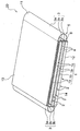
- FIG. 1 is a perspective view of the electrostatic actuator according to the first embodiment
- FIG. 2 is a front view of the electrostatic actuator in FIG. 2A
- FIG. 2B is a side view of the electrostatic actuator. Is shown.
- the electrostatic actuator 10 according to the present embodiment as shown in FIG. 1, the ribbon-shaped first electrode film 11 and the ribbon-shaped second electrode film 12 are laminated by being folded or joined. It is a laminated electrostatic actuator.
- the first electrode film 11 and the second electrode film 12 are film-like electrodes in which an electric conductor is insulated by an electric insulator, and are formed in an elongated shape like a ribbon. That is, the first electrode film 11 and the second electrode film 12 are formed in an elongated rectangular shape when they are not folded.
- copper foil or the like is used for the electric conductor
- PET (polyethylene terephthalate) or the like is used for the electric insulator.
- the stroke amount of the electrostatic actuator 10 is proportional to the number of laminated electrodes, a long stroke can be obtained by laminating a plurality of electrodes.
- the electrostatic actuator 10 when a voltage is applied to the laminated first electrode film 11 and the second electrode film 12, an electrostatic force is generated between the first electrode film 11 and the second electrode film 12.
- the entire electrostatic actuator 10 expands or contracts according to the polarity of the voltage applied to the first electrode film 11 and the second electrode film 12.
- the electrostatic actuator 10 is formed by folding a ribbon-shaped first electrode film 11 and a ribbon-shaped second electrode film 12 between one end 13 and the other end 14 of the electrostatic actuator 10.
- the electrostatic actuator 10 has a structure in which a plurality of first electrodes 1 formed of the first electrode film 11 and a plurality of second electrodes 2 formed of the second electrode film 12 are laminated. have.
- the first electrodes 1 are connected to each other by a hinge portion 3 which is a part of the first electrode film 11 like the first electrode 1.
- the second electrodes 2 are connected to each other by a hinge portion 4 which is a part of the second electrode film 12 like the second electrode 2.
- the plurality of first electrodes 1 are composed of a pair of end electrodes 1a and 1a and five intermediate electrodes 1b.
- the end electrodes 1a and 1a are positioned at one end 13 and the other end 14 of the electrostatic actuator 10 when the first electrode film 11 and the second electrode film 12 are laminated. These end electrodes 1a and 1a are adjacent to each other along the ribbon-like extending direction of the first electrode film 11, that is, the ends are in a straight ribbon-like state before the first electrode film 11 is folded. It is formed on the first electrode film 11 so that the portion corresponding to the intermediate electrode 1b is not located between the portions corresponding to the electrodes 1a and 1a.
- the intermediate electrode 1b is formed on the first electrode film 11 so as to be located between the end electrodes 1a and 1a when the first electrode film 11 and the second electrode film 12 are laminated.
- the first electrode film 11 is repeatedly bent in the same direction along a ribbon-like extending direction, and an intermediate electrode 1b is formed between a pair of end electrodes 1a and 1a. That is, the first electrode film 11 has a spirally wound shape when viewed from the side.
- the first electrode film 11 is formed so that the plurality of intermediate electrodes 1b overlap each other by being repeatedly and repeatedly bent in the same direction in a spiral shape along the ribbon-like extending direction.
- the electrostatic actuator 10 is composed of an outer portion 5 composed of a pair of end electrodes 1a coupled by an outer outer hinge portion 3a and a plurality of intermediate electrodes 1b coupled by an inner inner hinge portion 3b.
- the inner portion 6 and the inner portion 6 are nested.
- the second electrode film 12 is alternately bent by mountain folds and valley folds along the ribbon-like extending direction of the second electrode film 12. That is, the second electrode film 12 has a zigzag folded shape when viewed from the side.
- the second electrode film 12 is formed with six second electrodes 2 passing between each of the first electrodes 1 of the first electrode film 11.
- the tip 11a of the first electrode film 11 (see FIG. 2A) is joined to the second electrode film 12 at an intermediate position between one end 13 and the other end 14 of the electrostatic actuator 10. That is, in a state where the first electrode film 11 and the second electrode film 12 are joined before being folded, the tip end 11a of the first electrode film 11 is perpendicular to the center of the second electrode film 12. It is joined to form a T-shape.
- FIG. 3 shows a perspective view of the electrostatic actuator contracted
- FIG. 4 shows a perspective view of the electrostatic actuator extended.
- the ribbon-shaped electrode film used in this simulation has a width of 0.5 mm and a thickness of 4 ⁇ m.
- the electrostatic actuator 10 When voltages of different polarities are applied to the first electrode film 11 and the second electrode film 12, the electrostatic actuator 10 includes the first electrode 1 and the second electrode 2 as shown in FIG. Is pulled by electrostatic force and shrinks.
- the electrostatic actuator 10 when a voltage of the same polarity is applied to the first electrode film 11 and the second electrode film 12, as shown in FIG. 4, the first electrode 1 and the second electrode 2 and 2 are repulsed by electrostatic force and stretch.
- FIG. 5 shows a graph of spring characteristics of the electrostatic actuator.
- the vertical axis shows the spring constant in units of mN
- the horizontal axis shows the displacement amount of one end 13 or the other end 14 in units of ⁇ m.
- the electrostatic actuator 10 has a small spring constant in the drive region with a small displacement at one end 13 or the other end 14, and a spring constant in the overload region with a large displacement at one end 13 or the other end 14.
- the structure is large, and the ratio of the drive region to the overload region is 5 times or more, and ideal spring characteristics such as a disc spring can be obtained.
- the electrostatic actuators 10 are adjacent to each other along the ribbon-like extending direction of the first electrode film 11, and are located at one end 13 and the other end 14 of the electrostatic actuator 10 when laminated. It includes a pair of end electrodes 1a and 1a and an intermediate electrode 1b located between the end electrodes 1a and 1a when laminated.
- the spring characteristics in the overload region are greatly improved, and the ribbon-shaped electrode film can be thinned, so that a large electrostatic force can be generated even if the ribbon-shaped electrode film is formed.
- FIG. 6A and 6B show a perspective view of the electrostatic actuator according to the second embodiment
- FIG. 7A shows a front view of the electrostatic actuator according to the second embodiment
- FIG. 7B shows a second.
- a side view of the electrostatic actuator according to the embodiment is shown.
- the outer portion 5 of the first electrode film 1 is the same as that of the first embodiment, but the inner portion 6 is different from the first embodiment. ing.
- the inner portion 6 is mountain-folded along the direction in which the inner portion 6 extends in a ribbon shape of the first electrode film 11. It bends alternately due to the valley fold.
- the second electrode film 12 is also alternately bent by mountain folds and valley folds along the direction extending in a ribbon shape. Therefore, the intermediate electrode 1b of the first electrode film 11 is configured to be laminated alternately with the second electrode 2 of the second electrode film 12 at intervals.
- FIG. 8 shows a perspective view of the electrostatic actuator contracted
- FIG. 9 shows a perspective view of the electrostatic actuator extended.
- the electrostatic actuator 20 includes the first electrode 1 and the second electrode 2 as shown in FIG. 8 when voltages having different polarities are applied to the first electrode film 11 and the second electrode film 12. Is pulled by electrostatic force and shrinks.
- the electrostatic actuator 20 when a voltage of the same polarity is applied to the first electrode film 11 and the second electrode film 12, as shown in FIG. 9, the first electrode 1 and the second electrode 2 and 2 are repulsed by electrostatic force and stretch.
- FIG. 10 shows a graph of spring characteristics of the electrostatic actuator according to the second embodiment.
- the vertical axis shows the spring constant in units of mN
- the horizontal axis shows the displacement amount of one end 13 or the other end 14 in units of ⁇ m.
- the electrostatic actuator 20 has a small spring constant in the drive region with a small displacement at one end 13 or the other end 14, and a spring constant in the overload region with a large displacement at one end 13 or the other end 14.
- the structure is large, and the ratio of the drive region to the overload region is 5 times or more, and ideal spring characteristics such as a disc spring can be obtained.
- the present invention has been described above based on the embodiments, the present invention is not limited to this.
- the second electrode film 12 is alternately bent by mountain folds and valley folds along the ribbon-like extending direction of the second electrode film 12, but is not limited to this.
- the second electrode film 12 may be repeatedly bent in the same direction in a spiral shape along a ribbon-like extending direction as in the first electrode film 11 according to the first embodiment.
Landscapes
- Engineering & Computer Science (AREA)
- Power Engineering (AREA)
- Micromachines (AREA)
Priority Applications (5)
| Application Number | Priority Date | Filing Date | Title |
|---|---|---|---|
| CN202080044236.9A CN113994585A (zh) | 2019-06-18 | 2020-06-17 | 静电致动器 |
| JP2021528276A JP7566337B2 (ja) | 2019-06-18 | 2020-06-17 | 静電アクチュエータ |
| EP20827349.0A EP3989430A4 (en) | 2019-06-18 | 2020-06-17 | ELECTROSTATIC ACTUATOR |
| US17/619,328 US11848625B2 (en) | 2019-06-18 | 2020-06-17 | Electrostatic actuator |
| KR1020217042576A KR20220020836A (ko) | 2019-06-18 | 2020-06-17 | 정전 액추에이터 |
Applications Claiming Priority (2)
| Application Number | Priority Date | Filing Date | Title |
|---|---|---|---|
| JP2019112669 | 2019-06-18 | ||
| JP2019-112669 | 2019-06-18 |
Publications (1)
| Publication Number | Publication Date |
|---|---|
| WO2020255977A1 true WO2020255977A1 (ja) | 2020-12-24 |
Family
ID=74037151
Family Applications (1)
| Application Number | Title | Priority Date | Filing Date |
|---|---|---|---|
| PCT/JP2020/023659 Ceased WO2020255977A1 (ja) | 2019-06-18 | 2020-06-17 | 静電アクチュエータ |
Country Status (7)
| Country | Link |
|---|---|
| US (1) | US11848625B2 (https=) |
| EP (1) | EP3989430A4 (https=) |
| JP (1) | JP7566337B2 (https=) |
| KR (1) | KR20220020836A (https=) |
| CN (1) | CN113994585A (https=) |
| TW (1) | TW202130109A (https=) |
| WO (1) | WO2020255977A1 (https=) |
Families Citing this family (1)
| Publication number | Priority date | Publication date | Assignee | Title |
|---|---|---|---|---|
| US11888412B2 (en) * | 2017-07-14 | 2024-01-30 | Pixart Imaging Inc. | Stackable actuating element with profiled insulated electrode structures |
Citations (8)
| Publication number | Priority date | Publication date | Assignee | Title |
|---|---|---|---|---|
| US4330730A (en) * | 1980-03-27 | 1982-05-18 | Eastman Kodak Company | Wound piezoelectric polymer flexure devices |
| DE4127860A1 (de) * | 1991-08-22 | 1993-02-25 | Deutsche Aerospace | Pumpensystem zur foerderung von fluessigen oder gasfoermigen medien |
| JP2003199365A (ja) * | 2001-12-25 | 2003-07-11 | Matsushita Electric Works Ltd | 電歪ポリマーアクチュエータとその製造方法 |
| JP2008211922A (ja) * | 2007-02-27 | 2008-09-11 | Yamaha Corp | 高分子静電型アクチュエータ |
| JP2010057321A (ja) * | 2008-08-29 | 2010-03-11 | Tokyo Institute Of Technology | 静電アクチュエータおよびその製造方法 |
| JP2017022926A (ja) | 2015-07-14 | 2017-01-26 | 国立大学法人東京工業大学 | 静電アクチュエータおよび静電アクチュエータの製造方法 |
| JP2017158366A (ja) * | 2016-03-03 | 2017-09-07 | トヨタ自動車株式会社 | アクチュエータ |
| WO2018207707A1 (ja) * | 2017-05-10 | 2018-11-15 | ソニー株式会社 | アクチュエータ、駆動部材、触覚提示装置および駆動装置 |
Family Cites Families (8)
| Publication number | Priority date | Publication date | Assignee | Title |
|---|---|---|---|---|
| JP2001268948A (ja) * | 2000-03-21 | 2001-09-28 | Keiji Saneyoshi | 静電アクチュエータおよびそれを用いた動作機構 |
| ITPI20050095A1 (it) * | 2005-09-05 | 2005-12-05 | Federico Carpi | Attuatore, sensore e generator a polimeri elettroattivi in configurazione ripiegata |
| DE102008002495A1 (de) * | 2008-06-18 | 2009-12-24 | Robert Bosch Gmbh | Vielschichtaktor |
| DE102008002492A1 (de) * | 2008-06-18 | 2009-12-24 | Robert Bosch Gmbh | Faltaktor oder Faltsensor sowie Herstellungsverfahren für einen Faltaktor oder Faltsensor |
| JP5161006B2 (ja) * | 2008-08-29 | 2013-03-13 | 国立大学法人東京工業大学 | 静電アクチュエータの製造方法 |
| JP5318135B2 (ja) * | 2011-03-16 | 2013-10-16 | 株式会社東芝 | 静電アクチュエータ |
| US10903762B2 (en) * | 2015-09-02 | 2021-01-26 | Koninklijke Philips N.V. | Actuator device based on an electroactive or photoactive polymer |
| JP7408149B2 (ja) * | 2020-06-11 | 2024-01-05 | ストローブ株式会社 | 積層型静電アクチュエータ |
-
2020
- 2020-06-17 WO PCT/JP2020/023659 patent/WO2020255977A1/ja not_active Ceased
- 2020-06-17 CN CN202080044236.9A patent/CN113994585A/zh active Pending
- 2020-06-17 EP EP20827349.0A patent/EP3989430A4/en not_active Withdrawn
- 2020-06-17 TW TW109120400A patent/TW202130109A/zh unknown
- 2020-06-17 KR KR1020217042576A patent/KR20220020836A/ko not_active Ceased
- 2020-06-17 JP JP2021528276A patent/JP7566337B2/ja active Active
- 2020-06-17 US US17/619,328 patent/US11848625B2/en active Active
Patent Citations (8)
| Publication number | Priority date | Publication date | Assignee | Title |
|---|---|---|---|---|
| US4330730A (en) * | 1980-03-27 | 1982-05-18 | Eastman Kodak Company | Wound piezoelectric polymer flexure devices |
| DE4127860A1 (de) * | 1991-08-22 | 1993-02-25 | Deutsche Aerospace | Pumpensystem zur foerderung von fluessigen oder gasfoermigen medien |
| JP2003199365A (ja) * | 2001-12-25 | 2003-07-11 | Matsushita Electric Works Ltd | 電歪ポリマーアクチュエータとその製造方法 |
| JP2008211922A (ja) * | 2007-02-27 | 2008-09-11 | Yamaha Corp | 高分子静電型アクチュエータ |
| JP2010057321A (ja) * | 2008-08-29 | 2010-03-11 | Tokyo Institute Of Technology | 静電アクチュエータおよびその製造方法 |
| JP2017022926A (ja) | 2015-07-14 | 2017-01-26 | 国立大学法人東京工業大学 | 静電アクチュエータおよび静電アクチュエータの製造方法 |
| JP2017158366A (ja) * | 2016-03-03 | 2017-09-07 | トヨタ自動車株式会社 | アクチュエータ |
| WO2018207707A1 (ja) * | 2017-05-10 | 2018-11-15 | ソニー株式会社 | アクチュエータ、駆動部材、触覚提示装置および駆動装置 |
Non-Patent Citations (1)
| Title |
|---|
| See also references of EP3989430A4 |
Also Published As
| Publication number | Publication date |
|---|---|
| EP3989430A1 (en) | 2022-04-27 |
| JP7566337B2 (ja) | 2024-10-15 |
| TW202130109A (zh) | 2021-08-01 |
| JPWO2020255977A1 (https=) | 2020-12-24 |
| US11848625B2 (en) | 2023-12-19 |
| CN113994585A (zh) | 2022-01-28 |
| KR20220020836A (ko) | 2022-02-21 |
| US20220368248A1 (en) | 2022-11-17 |
| EP3989430A4 (en) | 2023-07-19 |
Similar Documents
| Publication | Publication Date | Title |
|---|---|---|
| JP5458288B2 (ja) | 静電アクチュエータおよびその製造方法 | |
| KR101998500B1 (ko) | 정전 액추에이터 및 정전 액추에이터의 제조 방법 | |
| US6933662B2 (en) | Electrostrictive compound actuator | |
| JP7566337B2 (ja) | 静電アクチュエータ | |
| US20190148619A1 (en) | Piezoelectric transformer | |
| JP2008211922A (ja) | 高分子静電型アクチュエータ | |
| WO2015107878A1 (ja) | 摩擦帯電現象を利用する折り重ね式発電機 | |
| JP5935104B2 (ja) | 静電アクチュエータおよびその製造方法 | |
| JP2020145768A (ja) | アクチュエータ | |
| JP7408149B2 (ja) | 積層型静電アクチュエータ | |
| US10122300B2 (en) | Row and column actuator control | |
| US11677337B2 (en) | Comb drive for microelectromechanical system | |
| JPH06296380A (ja) | 積層型伸縮アクチュエータ | |
| WO2020209187A1 (ja) | 静電アクチュエータ組立体 | |
| US8299683B2 (en) | Ultrasonic motor | |
| JPWO2020255977A5 (https=) | ||
| US9484520B2 (en) | Method for producing flexible EAP generators | |
| JPH0715981A (ja) | 静電式アクチュエータ | |
| JP2024108571A (ja) | 静電式アクチュエータ及び静電式アクチュエータユニット | |
| JP6737220B2 (ja) | 可変焦点ミラー | |
| JPH04281371A (ja) | 静電アクチュエータの電極パターン | |
| JPH06315280A (ja) | 静電アクチュエータ | |
| JP2012029419A (ja) | アクチュエータ |
Legal Events
| Date | Code | Title | Description |
|---|---|---|---|
| 121 | Ep: the epo has been informed by wipo that ep was designated in this application |
Ref document number: 20827349 Country of ref document: EP Kind code of ref document: A1 |
|
| ENP | Entry into the national phase |
Ref document number: 2021528276 Country of ref document: JP Kind code of ref document: A |
|
| NENP | Non-entry into the national phase |
Ref country code: DE |
|
| ENP | Entry into the national phase |
Ref document number: 20217042576 Country of ref document: KR Kind code of ref document: A |
|
| ENP | Entry into the national phase |
Ref document number: 2020827349 Country of ref document: EP Effective date: 20220118 |