WO2020250622A1 - 液体分析装置及びセンサユニット - Google Patents
液体分析装置及びセンサユニット Download PDFInfo
- Publication number
- WO2020250622A1 WO2020250622A1 PCT/JP2020/019537 JP2020019537W WO2020250622A1 WO 2020250622 A1 WO2020250622 A1 WO 2020250622A1 JP 2020019537 W JP2020019537 W JP 2020019537W WO 2020250622 A1 WO2020250622 A1 WO 2020250622A1
- Authority
- WO
- WIPO (PCT)
- Prior art keywords
- sensor unit
- unit
- sensor
- conversion unit
- conversion
- Prior art date
- Legal status (The legal status is an assumption and is not a legal conclusion. Google has not performed a legal analysis and makes no representation as to the accuracy of the status listed.)
- Ceased
Links
Images


Classifications
-
- G—PHYSICS
- G01—MEASURING; TESTING
- G01R—MEASURING ELECTRIC VARIABLES; MEASURING MAGNETIC VARIABLES
- G01R1/00—Details of instruments or arrangements of the types included in groups G01R5/00 - G01R13/00 and G01R31/00
- G01R1/02—General constructional details
- G01R1/06—Measuring leads; Measuring probes
- G01R1/067—Measuring probes
-
- G—PHYSICS
- G01—MEASURING; TESTING
- G01N—INVESTIGATING OR ANALYSING MATERIALS BY DETERMINING THEIR CHEMICAL OR PHYSICAL PROPERTIES
- G01N33/00—Investigating or analysing materials by specific methods not covered by groups G01N1/00 - G01N31/00
- G01N33/18—Water
-
- H—ELECTRICITY
- H03—ELECTRONIC CIRCUITRY
- H03M—CODING; DECODING; CODE CONVERSION IN GENERAL
- H03M1/00—Analogue/digital conversion; Digital/analogue conversion
- H03M1/12—Analogue/digital converters
Definitions
- the present invention relates to a liquid analyzer for analyzing a liquid and a sensor unit for analyzing a liquid.
- Patent Document 1 For example, as a device for measuring pH, dissolved oxygen, etc. in a liquid such as environmental water, industrial water, or water being treated with sewage, as shown in Patent Document 1, detection according to a predetermined measurement target item by being immersed in the liquid. Some include a sensor unit that outputs a signal and a device main body that acquires a detection signal from the sensor unit and displays a measured value.
- the sensor unit includes a sensor unit that outputs an analog signal according to the measurement target item, a conversion unit that amplifies the analog signal from the sensor unit and converts it into a digital signal, and an accommodating body that accommodates them. have.
- the portion in which the accommodating body accommodates the sensor portion and the portion accommodating the A / D conversion unit cannot be separated. Therefore, when the sensor unit is replaced due to deterioration of the sensor unit or the like, it is necessary to replace the conversion unit which normally does not need to be replaced, which increases the running cost.
- the inventor of the present application mutually exchanges a sensor unit that is immersed in a liquid and outputs an analog signal corresponding to a predetermined measurement target item and a conversion unit that converts an analog signal obtained by the sensor unit into a digital signal.
- the sensor unit has a connection plug for electrically connecting to the conversion unit.
- electromagnetic noise may be added to the analog signal from the connection portion between the connection plug and the wiring of the sensor unit.
- the present invention has been made to solve the above problems, and its main object is to reduce the running cost in the liquid analyzer and to reduce the electromagnetic noise superimposed on the analog signal. ..
- the liquid analyzer has a sensor unit that is immersed in a liquid and outputs an analog signal corresponding to a predetermined measurement target item, and a conversion unit that converts the analog signal obtained by the sensor unit into a digital signal.
- a device main body in which the conversion unit is connected by wire or wirelessly to acquire a digital signal from the conversion unit, and the sensor unit and the conversion unit are configured to be detachable from each other. It has a connection plug for electrically connecting to the conversion unit, and is characterized in that a metal shield is provided at a connection portion between the connection plug and the wiring of the sensor unit.
- a sensor capable of detecting a value indicating the properties of the liquid such as a pH sensor, a dissolved oxygen sensor, a conductivity sensor, an oxidation-reduction potential sensor, an ion concentration sensor such as calcium or potassium, and a turbidity sensor can be considered.
- the pH sensor is particularly susceptible to the influence of electromagnetic noise, and the SN ratio becomes poor. Therefore, it is desirable that the metal shield is provided in the sensor unit for measuring pH as a measurement target item.
- the conversion unit has a notification unit for notifying that the output of the sensor unit is stable during measurement and calibration.
- the device main body can acquire the measurement results of a plurality of measurement points or a plurality of measurement target items by connecting the plurality of conversion units to which the sensor units are attached.
- the connecting mechanism is at least one of the positions from the bottom of the water to the sensing portion (for example, in the case of a glass electrode, the response glass) or the position from the water surface to the sensing portion in each of the sensor portions mounted on the plurality of conversion portions. It is desirable that the plurality of conversion units are connected so that the two are at the same position. With this configuration, it becomes easy to install a plurality of sensor units at, for example, the same depth position.
- a plurality of measurement target items can be measured at once as long as a plurality of conversion units equipped with a plurality of sensor units having different measurement target items are connected to the device main body. ..
- the apparatus main body has a calibration unit that simultaneously calibrates a plurality of the sensor units having different measurement target items.
- simultaneous calibration means that the timing at which the calibration of the plurality of sensors is started is the same, and the calibration processes after the start are performed in parallel.
- the calibration of each sensor unit can be performed at once, so that the calibration time can be shortened.
- the apparatus main body calibrates a plurality of the sensor units having different measurement target items with calibration substances of different types.
- the device main body has a connection port to which a cable extending from the conversion unit is connected and a sensor recognition unit that recognizes a sensor unit attached to the conversion unit connected to the connection port.
- the device body When considering performing liquid analysis not only with the device body held in the hand but also with the device body placed, the device body is provided with a stand member that supports the device body in an inclined or upright state. Is possible. In this configuration, it is desirable that the stand member is configured so that a cable connecting the conversion unit and the device main body can be wound around. With this configuration, the cables can be bundled together, and the cables are less likely to get in the way when carrying the liquid analyzer or storing the liquid analyzer.
- the sensor unit according to the present invention has a sensor unit that comes into contact with a liquid and outputs an analog signal according to a predetermined measurement target item, and a sensor unit that converts the analog signal obtained by the sensor unit into a digital signal and outputs the analog signal to the outside.
- the sensor unit and the conversion unit are configured to be detachable from each other, it is not necessary to replace only the sensor unit and the conversion unit when the sensor unit is replaced.
- the running cost of the liquid analyzer can be reduced.
- the liquid analyzer 100 of the present embodiment measures a predetermined measurement target item of a liquid to be measured, such as environmental water such as rivers, swamp lakes, and oceans, industrial water, and water during sewage treatment.
- the items to be measured include pH, conductivity (EC), dissolved oxygen (DO), oxidation-reduction potential (ORP), ion concentration of calcium and potassium, turbidity, and amount of cells such as chlorophyll and cyanobacteria. , Nitrate concentration, and a value indicating the properties of the liquid containing at least one of the ammonium concentration, water depth, water level, and the like.
- a liquid analyzer 100 capable of measuring three measurement target items of pH, conductivity (EC), and dissolved oxygen (DO) will be described.
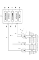
- the liquid analyzer 100 is an immersion type used for, for example, field measurement, and as shown in FIGS. 1 and 2, a sensor unit 2 for immersing in a liquid and measuring a predetermined measurement target item. And a device main body 3 to which the sensor unit 2 is connected.
- the sensor unit 2 and the device main body 3 are connected by a cable C for signal transmission and a power supply.
- Sensor unit> a sensor unit 2 for pH measurement, a sensor unit 2 for EC measurement, and a sensor unit 2 for DO measurement are provided.
- each sensor unit 2 has a sensor unit 21 that comes into contact with a liquid and outputs an analog signal according to a predetermined measurement target item, and a digital signal of the analog signal obtained by the sensor unit 21. It has a conversion unit 22 for converting to.
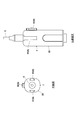
- FIG. 3 shows the sensor unit 2 for pH measurement.
- each sensor unit 2 is used by the user holding the conversion unit 22 in his / her hand. More specifically, the sensor unit 21 comes into contact with the liquid by immersing the sensor unit 2 in the liquid while the user holds the conversion unit 22 in his / her hand.
- the sensor unit 21 is provided with a component for measuring the measurement target item according to the measurement target item.
- a component for measuring the measurement target item for example, when the sensor unit 21 is a pH sensor that measures pH as a measurement target item, a glass electrode for pH measurement, a comparison electrode, a reference electrode, a temperature compensation electrode, and the like are provided.
- the sensor unit 21 is an EC sensor that measures EC as a measurement target item, two electrodes or four electrodes for EC measurement are provided.
- a DO sensor in which the sensor unit 21 measures DO as a measurement target item, a sensitive film that emits an amount of fluorescence depending on the oxygen concentration, and a light source that irradiates the sensitive film with excitation light that excites fluorescence.
- a photodetector that receives the fluorescence emitted from the sensitive film is provided.
- parts for measuring the measurement target item are held inside, for example, a straight tubular support tube 211.
- the conversion unit 22 converts the analog signal obtained by the sensor unit 21 into a digital signal.
- the conversion unit 22 includes an amplifier that amplifies the analog signal of the sensor unit 21 and an AD converter that digitally converts the amplified analog signal.
- the conversion unit 22 is dedicated to each sensor unit. That is, when the sensor unit 21 is a pH sensor, it is a conversion unit 22 for a pH sensor, when the sensor unit 21 is an EC sensor, it is a conversion unit 22 for an EC sensor, and when the sensor unit 21 is a DO sensor. Is a conversion unit 22 for a DO sensor.
- each conversion unit 22 an amplifier and an AD converter are provided on the circuit board 221.
- the circuit board 221 is housed in the housing 222 of the conversion unit 22.
- a cable C electrically connected to the circuit board 221 is connected to the upper end of the housing 222, and the digital signal obtained by the conversion unit 22 is transmitted to the device main body 3 via the cable C. ..
- the sensor unit 2 of the present embodiment is configured to be detachable by the sensor unit 21 and the conversion unit 22.
- connection plug 212 for electrically connecting to the conversion unit 22 is provided at the upper end of the support tube 211 of the sensor unit 21. As shown in FIG. 4, the connection plug 212 is electrically connected to the wiring 21w of the sensor unit 21 by, for example, soldering. Further, an insertion portion 223 into which the connection plug 212 is inserted is formed at the lower end portion of the housing 222 of the conversion portion 22. By inserting the connection plug 212 of the sensor unit 21 into the insertion portion 223, the connection plug 212 comes into contact with the connection terminal 221x provided on the circuit board 221 inside the housing 222 and is electrically connected.
- the sensor unit 21 and the conversion unit 22 are provided with a sealing mechanism 4 for liquid-tightly sealing them in a connected state.
- the seal mechanism 4 has an O-ring (not shown) interposed between the housing 222 of the conversion unit 22 and the support tube 211 of the sensor unit 21, and tightening for crushing the O-ring by the housing 222 and the support tube 211. It consists of a structure 41.
- the tightening structure 41 includes, for example, a screw portion provided on the outer peripheral surface of the housing 222 and a nut portion provided on the support pipe 211 and screwed into the screw portion.
- the seal mechanism 4 ensures the liquidtightness of the connection portion between the sensor unit 21 and the conversion unit 22, and strengthens the connection between the sensor unit 21 and the conversion unit 22.
- a metal shield 5 is provided at the connection portion between the connection plug 212 and the wiring 21w in the pH sensor.
- the metal shield 5 is, for example, a brass pipe having a cylindrical shape, and is provided so as to surround the connecting portion.
- the metal shield 5 may be provided on the other sensor unit 21.
- the device main body 3 to which the sensor unit 2 configured in this way is connected has a measurement value calculation unit 3a that calculates the measurement value of each measurement target item based on the digital signal acquired from the connected sensor unit 2. (See Fig. 2). Further, as shown in FIG. 1, on the front surface of the apparatus main body 3, a display 31 for displaying the measurement result of the connected sensor unit 2 and the connected sensor unit 2 can be controlled or the display can be switched. It has an operation button group 32 for the operation.
- the device main body 3 is a computer having a CPU, an internal memory, an input / output interface, and the like.
- Reference numeral 34 in FIG. 1 is a cover that protects an output port for printing and a USB port.
- FIG. 5 shows an example of screen display by the display control unit 3b.
- FIG. 5A is a display screen for displaying the measurement result when the pH sensor is connected to the apparatus main body 3.
- FIG. 5B is a display screen for displaying the measurement results when the pH sensor and the EC sensor are connected to the apparatus main body 3.
- FIG. 5C is a display screen for displaying the measurement results when the pH sensor, EC sensor and DO sensor are connected to the device main body 3.
- the display screen when a plurality of sensors are connected, the display screen is divided to display a list of a plurality of measurement target items, but it is also possible to switch to each measurement target item for display. You can do it, and you can also set the number of items to display.
- the operation button group 32 displays a “calibration (CAL) button” for starting calibration, a “measurement (MEAS) button” for starting measurement, and historical data.
- Data (DATA) button "Mode (MODE) button” for changing measurement parameters during measurement, for example, “Setting (SET) button” for setting display display, etc., measurement during measurement or calibration
- “Enter button” to determine the value to be recorded
- “Move (UP, DOWN, LEFT, RIGHT) button” to move up, down, left and right
- Power (POWER) button to turn the power on / off. It is included.
- the apparatus main body 3 is provided with a plurality of (three in this case) connection ports P1 to P3 so that a plurality of sensor units 2 having different measurement target items can be connected at the same time.
- These three connection ports P1 to P3 have the same shape, and the above three sensor units 2 (conversion unit 22) can be connected without distinction. That is, any one of the three conversion units 22 can be connected to the first connection port P1, and any one of the three conversion units 22 can be connected to the second connection port P2. Yes, any one of the three conversion units 22 can be connected to the third connection port P3.
- the connection terminals of the cables C connected to each of the three conversion units 22 also have the same shape according to the connection ports P1 to P3.
- the device main body 3 has a sensor recognition unit 3c that recognizes the sensor unit 21 mounted on the conversion unit 22 connected to each connection port P1 to P3.
- the sensor recognition unit 3c has a database including an identifier set in each conversion unit 22 and the type of sensor associated with the identifier, and the conversion unit 22 connected to the connection ports P1 to P3.
- the identifier set in the conversion unit 22 is acquired from the above, and the sensor unit 21 connected to the connection ports P1 to P3 is recognized in light of the database.
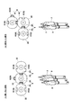
- the liquid analyzer 100 of the present embodiment has a connecting mechanism 6 for connecting a plurality of conversion units 22 to each other.
- This connecting mechanism 6 connects a plurality of conversion units 22 so that the sensor units 21 mounted on them face in the same direction.
- the connecting mechanism 6 is composed of a concave portion 61 formed on the side surface of each conversion portion 22 and a convex portion 62 fitted in the concave portion 61.
- the concave portion 61 is a concave groove extending in the vertical direction, and the upper end portion thereof is open.
- the convex portion 62 is a convex strip that slides into the concave groove and fits into the concave groove.
- each conversion unit 22 in each conversion unit 22, one concave portion 61 is formed on each side surface (left and right side surface) corresponding to each other, and one convex portion 62 is formed on the back surface.
- the three conversion portions 22 can be connected in a horizontal row (see FIG. 8A), and the three conversion portions 22 are formed at right angles (see FIG. 8A). It can also be connected in an L shape (see FIG. 8 (B)).
- the conversion unit 22 is connected by sliding it up and down, but by changing the forming direction of the concave portion 61 and the convex portion 62, for example, it can be slid and moved from the lateral direction. However, it can also be configured to slide from an oblique direction.
- the connecting mechanism 6 connects the plurality of conversion units 22 so that the sensor units 21 mounted on the plurality of conversion units 22 are located at the same height as each other. That is, the connecting mechanism 6 has at least one of the positions from the bottom of the water to the sensing portion and the position from the water surface to the sensing portion in each of the sensor units 21 mounted on the plurality of conversion units 22 at the same position.
- a plurality of conversion units 22 are connected to the above.
- the sensing portion of each sensor unit 21 is a response film of a glass electrode in the case of a pH sensor, an electrode in the case of an EC sensor, and a sensitive film in the case of a DO sensor.
- the sensor units 21 are at the same height as each other by connecting the plurality of conversion units 22 by the connecting mechanism 6. It becomes the position.
- a concave portion 33 into which the convex portion 62 formed in the conversion unit 22 is fitted is formed on the side surface of the device main body 3, so that the conversion unit 22 can be connected and fixed to the device main body 3 (FIG. FIG. 1).
- the conversion unit 22 has a notification unit 7 that notifies that the output of the sensor unit 21 is stable during measurement and calibration.
- the notification unit 7 uses light to notify whether or not the output of the sensor unit 21 is stable.
- the notification unit 7 is a lamp such as an LED provided exposed on the front surface of the housing 222 of the conversion unit 22.
- the notification unit 7 lights up (blinks) intermittently before the output of the sensor unit 21 (that is, the value measured by the sensor unit 2) stabilizes, and continuously when the output of the sensor unit 21 stabilizes. It is controlled to light up.
- This lighting control may be performed by a control unit (not shown) provided on the circuit board of the conversion unit 22, or may be performed by the measurement control unit 3d provided on the apparatus main body 3. Is also good.
- the display control unit 3b of the apparatus main body 3 has a hold function that automatically and fixedly displays the measured value displayed on the display 31 after the measured value by the sensor unit 2 is stabilized. ..
- This hold function is automatically canceled when the difference between the measured value at the time of holding and the measured value after holding becomes a predetermined value or more. It can also be canceled manually by the user pressing the "measurement (MEAS) button" or the like.
- the notification unit 7 is configured so that the conversion unit 22 is connected to the device main body 3 via the cable C so that power is supplied from the device main body 3 and the light is intermittently lit (blinks), for example. From this, it is also possible to know whether or not the conversion unit 22 is securely connected to the device main body 3 by the notification unit 7.
- the lighting at the time of connection may be performed after the sensor recognition unit 3c recognizes the sensor unit 21. From this, it can be known whether or not the sensor unit 21 is recognized after the connection.
- the apparatus main body 3 of the present embodiment is configured so that a plurality of sensor units 21 having different measurement target items can be calibrated at the same time. That is, in this embodiment, the pH sensor, the EC sensor, and the DO sensor can be calibrated at the same time.
- the apparatus main body 3 has a calibration unit 3e that simultaneously calibrates a plurality of sensor units 21 having different measurement target items.
- the pH sensor is immersed in the pH sensor calibration solution
- the EC sensor is immersed in the EC sensor calibration solution
- the DO sensor is exposed to the air.
- each sensor unit 21 is calibrated with calibration substances such as calibration solutions of different types.
- calibration (CAL) button pressing the operation button (“calibration (CAL) button” of the apparatus main body 3
- calibration of each sensor unit 21 is started at the same time as shown in FIG.
- an analog signal is output from each sensor unit 21 and converted into a digital signal by the conversion unit 22.
- the measured value calculation unit 3a of the apparatus main body 3 calculates the measured value indicated by the digital signal.
- the calibration unit 3e calibrates each sensor from the measured value obtained by the measured value calculation unit 3a and the value of each calibration solution. In this way, the calibration process for each sensor unit 21 after the start of calibration is performed in parallel.
- the calibration unit 3e can also automatically recognize the calibration solution from the measured value obtained at the time of calibration. Specifically, the calibration unit 3e has a database of calibration solutions, compares the measured values obtained at the time of calibration with the database, identifies the calibration solution used for calibration, and determines the calibration solution of the specified calibration solution. Calibrate using the values.
- the device main body 3 of the present embodiment is provided with a stand member 8 that supports the device main body 3 in an inclined or upright state.
- the stand member 8 is provided so as to be storable on the back surface of the device main body 3 (the surface opposite to the front surface on which the display 31 is provided).
- the stand member 8 is rotatably provided between a storage position housed on the back surface of the device body 3 and a support position for supporting the device body 3 in an inclined or upright state.
- the stand member 8 is configured so that the cable C can be wound around it.
- FIG. 10B shows an example in which the cable C is wound around the stand member 8 and the device main body 3, it may be wound only around the stand member 8. By forming a recess on the side side of the stand member 8, the bulkiness of the cable C can be reduced in the state of being wound around the stand member 8.
- the sensor unit 21 and the conversion unit 22 are configured to be detachable from each other. Therefore, when the sensor unit 21 is replaced, only the sensor unit 21 is replaced. Therefore, it is not necessary to replace the conversion unit 22, and the running cost of the liquid analyzer 100 can be reduced. Since the metal shield 5 is provided at the connection portion between the connection plug 212 and the wiring 21w of the sensor unit 21, electromagnetic noise superimposed on the analog signal is generated from the connection portion between the connection plug 212 and the wiring 21w of the sensor unit 21. It can be reduced and the measurement accuracy can be improved.
- the device main body 3 and the sensor unit 2 are connected by a cable, but the device main body 3 and the sensor unit 2 may be wirelessly connected.
- the device main body 3 may be provided with a voice recognition function.
- the device main body 3 may have a voice recognition unit, and for example, when a user makes a voice such as "measurement” or "calibration", the device main body 3 may be configured to recognize the voice and measure or calibrate the voice.
- This voice recognition function is particularly effective when the device main body 3 and the sensor unit 2 are separated from each other and the user cannot operate the device main body 3 and the sensor unit 2 at the same time.
- the device main body 3 acquires the digital signal from the sensor unit 2 and calculates the measured value, but the conversion unit 22 may calculate the measured value. In this case, a digital signal indicating the measured value is transmitted to the device main body 3 to the device main body 3.
- the connecting mechanism 6 connects a plurality of conversion units 22 so that the sensor units 21 mounted on them face in the same direction.
- the connection mechanism 6 connects a plurality of conversion units 22 so that the sensor units 21 mounted on them face in the same direction.
- the connection mechanism 6 uses the plurality of sensor units 2. More specifically, the sensor unit 21 comes into contact with the liquid by immersing the plurality of sensor units 2 in the liquid while the user holds each cable C in one hand.
- the liquid analyzer 100 does not require the user to adjust the position of each sensor unit 2 in water.
- the liquid analyzer 100 for measuring pH, EC and DO is exemplified as the measurement target item, but by connecting the sensor unit 2 for measuring other measurement target items to the device main body 3, the pH can be adjusted. It is possible to measure measurement target items other than EC and DO.
Landscapes
- Life Sciences & Earth Sciences (AREA)
- Chemical & Material Sciences (AREA)
- Health & Medical Sciences (AREA)
- Physics & Mathematics (AREA)
- General Physics & Mathematics (AREA)
- Engineering & Computer Science (AREA)
- Medicinal Chemistry (AREA)
- Analytical Chemistry (AREA)
- Biochemistry (AREA)
- General Health & Medical Sciences (AREA)
- Food Science & Technology (AREA)
- Immunology (AREA)
- Pathology (AREA)
- Investigating Or Analyzing Materials By The Use Of Electric Means (AREA)
Priority Applications (3)
| Application Number | Priority Date | Filing Date | Title |
|---|---|---|---|
| US17/595,431 US12222368B2 (en) | 2019-06-10 | 2020-05-15 | Liquid analysis device and sensor unit |
| JP2021525957A JP7479366B2 (ja) | 2019-06-10 | 2020-05-15 | 液体分析装置及びセンサユニット |
| EP20821722.4A EP3957985B1 (en) | 2019-06-10 | 2020-05-15 | Liquid analysis device |
Applications Claiming Priority (2)
| Application Number | Priority Date | Filing Date | Title |
|---|---|---|---|
| JP2019108265 | 2019-06-10 | ||
| JP2019-108265 | 2019-06-10 |
Publications (1)
| Publication Number | Publication Date |
|---|---|
| WO2020250622A1 true WO2020250622A1 (ja) | 2020-12-17 |
Family
ID=73656078
Family Applications (1)
| Application Number | Title | Priority Date | Filing Date |
|---|---|---|---|
| PCT/JP2020/019537 Ceased WO2020250622A1 (ja) | 2019-06-10 | 2020-05-15 | 液体分析装置及びセンサユニット |
Country Status (5)
| Country | Link |
|---|---|
| US (1) | US12222368B2 (https=) |
| EP (1) | EP3957985B1 (https=) |
| JP (1) | JP7479366B2 (https=) |
| CN (2) | CN212622539U (https=) |
| WO (1) | WO2020250622A1 (https=) |
Cited By (1)
| Publication number | Priority date | Publication date | Assignee | Title |
|---|---|---|---|---|
| JP2024011528A (ja) * | 2022-07-14 | 2024-01-25 | 東亜ディーケーケー株式会社 | 計測装置 |
Families Citing this family (1)
| Publication number | Priority date | Publication date | Assignee | Title |
|---|---|---|---|---|
| JP7479366B2 (ja) | 2019-06-10 | 2024-05-08 | 株式会社 堀場アドバンスドテクノ | 液体分析装置及びセンサユニット |
Citations (16)
| Publication number | Priority date | Publication date | Assignee | Title |
|---|---|---|---|---|
| JPS5246892A (en) * | 1975-10-11 | 1977-04-14 | Hitachi Ltd | Ion selecting electrode |
| JPS5363889U (https=) * | 1976-10-27 | 1978-05-30 | ||
| JPS58103658A (ja) * | 1981-12-16 | 1983-06-20 | Shimadzu Corp | レフアレンス電極 |
| JPH04127566U (ja) * | 1991-05-13 | 1992-11-20 | 株式会社東芝 | 塗膜劣化測定用プローブ |
| JPH11153594A (ja) * | 1997-11-20 | 1999-06-08 | Horiba Ltd | 水質測定装置 |
| JP2004286685A (ja) * | 2003-03-24 | 2004-10-14 | Denso Corp | ガス濃度検出装置 |
| JP2005077252A (ja) * | 2003-09-01 | 2005-03-24 | Horiba Ltd | 比較電極およびイオン濃度計 |
| JP2005114697A (ja) * | 2003-10-10 | 2005-04-28 | Dkk Toa Corp | 計測装置 |
| JP2010151729A (ja) * | 2008-12-26 | 2010-07-08 | Yokogawa Electric Corp | 計測システム |
| US20110204876A1 (en) * | 2008-10-30 | 2011-08-25 | Endress Hauser Conduora | Modular measuring device with distributed data and algorithms |
| JP2013142964A (ja) * | 2012-01-10 | 2013-07-22 | Yokogawa Electric Corp | 液分析用スマートセンサ |
| US20140012530A1 (en) * | 2012-07-09 | 2014-01-09 | Endress + Hauser Conducta Gesellschaft für Mess- und Regeltechnik mbH + Co. KG | Arrangement and Method for Calibrating at Least Two Sensors in Parallel |
| US20150300981A1 (en) * | 2012-09-14 | 2015-10-22 | Hamilton Bonaduz Ag | Potentiometric sensor element and method for producing same |
| US20160354786A1 (en) * | 2014-02-14 | 2016-12-08 | Elements S.R.L. | High sensitivity multichannel detection device |
| CN206208882U (zh) * | 2016-12-07 | 2017-05-31 | 候鹏飞 | 一种水质检验用组装仪器 |
| JP2019020246A (ja) | 2017-07-14 | 2019-02-07 | 株式会社 堀場アドバンスドテクノ | 蛍光式溶存酸素計 |
Family Cites Families (12)
| Publication number | Priority date | Publication date | Assignee | Title |
|---|---|---|---|---|
| IE860790L (en) * | 1987-09-22 | 1988-03-26 | Patrick Smyth | Monitoring the parameters of a fluid using an infra-red transmitter and receiver |
| JPH08110241A (ja) * | 1994-10-13 | 1996-04-30 | Suzuki Shiyoukan:Kk | センサ支持装置 |
| US6487912B1 (en) * | 1999-09-28 | 2002-12-03 | Rosemount Inc. | Preinstallation of a pressure sensor module |
| US6834560B1 (en) | 2002-07-12 | 2004-12-28 | Phionics, Inc. | Groundwater sensor array for insertion into a narrow-bore well |
| US8124028B2 (en) * | 2005-07-25 | 2012-02-28 | Agilent Technologies, Inc. | Automated liquid handling device and associated assay unit |
| US7943092B2 (en) * | 2006-10-10 | 2011-05-17 | Oakland University | Portable surface plasmon resonance biosensor |
| CN203606890U (zh) * | 2013-10-22 | 2014-05-21 | 宁波腾阳电器有限公司 | 多磁头组合型验钞机传感器 |
| CA2967329C (en) | 2014-11-10 | 2022-11-22 | In-Situ, Inc. | Submersible multi-parameter sonde having a high sensor form factor sensor |
| US11067527B2 (en) | 2016-12-16 | 2021-07-20 | Siemens Healthcare Diagnostics Inc. | Sensor assembly having microsensors |
| JP2018146533A (ja) | 2017-03-09 | 2018-09-20 | 横河電機株式会社 | センサ校正装置およびセンサ校正方法 |
| CN207456517U (zh) | 2017-11-14 | 2018-06-05 | 海南电网有限责任公司电力科学研究院 | 一种信号转换装置 |
| JP7479366B2 (ja) | 2019-06-10 | 2024-05-08 | 株式会社 堀場アドバンスドテクノ | 液体分析装置及びセンサユニット |
-
2020
- 2020-05-15 JP JP2021525957A patent/JP7479366B2/ja active Active
- 2020-05-15 US US17/595,431 patent/US12222368B2/en active Active
- 2020-05-15 WO PCT/JP2020/019537 patent/WO2020250622A1/ja not_active Ceased
- 2020-05-15 EP EP20821722.4A patent/EP3957985B1/en active Active
- 2020-05-29 CN CN202020959175.6U patent/CN212622539U/zh active Active
- 2020-05-29 CN CN202010472868.7A patent/CN112067766B/zh active Active
Patent Citations (16)
| Publication number | Priority date | Publication date | Assignee | Title |
|---|---|---|---|---|
| JPS5246892A (en) * | 1975-10-11 | 1977-04-14 | Hitachi Ltd | Ion selecting electrode |
| JPS5363889U (https=) * | 1976-10-27 | 1978-05-30 | ||
| JPS58103658A (ja) * | 1981-12-16 | 1983-06-20 | Shimadzu Corp | レフアレンス電極 |
| JPH04127566U (ja) * | 1991-05-13 | 1992-11-20 | 株式会社東芝 | 塗膜劣化測定用プローブ |
| JPH11153594A (ja) * | 1997-11-20 | 1999-06-08 | Horiba Ltd | 水質測定装置 |
| JP2004286685A (ja) * | 2003-03-24 | 2004-10-14 | Denso Corp | ガス濃度検出装置 |
| JP2005077252A (ja) * | 2003-09-01 | 2005-03-24 | Horiba Ltd | 比較電極およびイオン濃度計 |
| JP2005114697A (ja) * | 2003-10-10 | 2005-04-28 | Dkk Toa Corp | 計測装置 |
| US20110204876A1 (en) * | 2008-10-30 | 2011-08-25 | Endress Hauser Conduora | Modular measuring device with distributed data and algorithms |
| JP2010151729A (ja) * | 2008-12-26 | 2010-07-08 | Yokogawa Electric Corp | 計測システム |
| JP2013142964A (ja) * | 2012-01-10 | 2013-07-22 | Yokogawa Electric Corp | 液分析用スマートセンサ |
| US20140012530A1 (en) * | 2012-07-09 | 2014-01-09 | Endress + Hauser Conducta Gesellschaft für Mess- und Regeltechnik mbH + Co. KG | Arrangement and Method for Calibrating at Least Two Sensors in Parallel |
| US20150300981A1 (en) * | 2012-09-14 | 2015-10-22 | Hamilton Bonaduz Ag | Potentiometric sensor element and method for producing same |
| US20160354786A1 (en) * | 2014-02-14 | 2016-12-08 | Elements S.R.L. | High sensitivity multichannel detection device |
| CN206208882U (zh) * | 2016-12-07 | 2017-05-31 | 候鹏飞 | 一种水质检验用组装仪器 |
| JP2019020246A (ja) | 2017-07-14 | 2019-02-07 | 株式会社 堀場アドバンスドテクノ | 蛍光式溶存酸素計 |
Non-Patent Citations (1)
| Title |
|---|
| See also references of EP3957985A4 |
Cited By (2)
| Publication number | Priority date | Publication date | Assignee | Title |
|---|---|---|---|---|
| JP2024011528A (ja) * | 2022-07-14 | 2024-01-25 | 東亜ディーケーケー株式会社 | 計測装置 |
| JP7513912B2 (ja) | 2022-07-14 | 2024-07-10 | 東亜ディーケーケー株式会社 | 計測装置 |
Also Published As
| Publication number | Publication date |
|---|---|
| EP3957985A1 (en) | 2022-02-23 |
| EP3957985B1 (en) | 2026-04-29 |
| JPWO2020250622A1 (https=) | 2020-12-17 |
| CN112067766B (zh) | 2025-04-29 |
| CN112067766A (zh) | 2020-12-11 |
| US20220196703A1 (en) | 2022-06-23 |
| CN212622539U (zh) | 2021-02-26 |
| US12222368B2 (en) | 2025-02-11 |
| JP7479366B2 (ja) | 2024-05-08 |
| EP3957985A4 (en) | 2023-01-04 |
Similar Documents
| Publication | Publication Date | Title |
|---|---|---|
| US5233860A (en) | Water measuring system with improved calibration | |
| US6176988B1 (en) | Membrane electrode for measuring the glucose concentration in fluids | |
| US5103179A (en) | Water analyzer with multiple electrodes | |
| KR101526217B1 (ko) | 현장용 스마트 용존산소 분석기 | |
| DE3883289D1 (de) | Sensoren fuer saure gase. | |
| JP7479366B2 (ja) | 液体分析装置及びセンサユニット | |
| JP6875645B2 (ja) | 計測装置 | |
| JP7265631B2 (ja) | 検査方法、システム、及び、プログラム | |
| US4314029A (en) | Apparatus for automatically measuring changes in amount of gas | |
| CN103257174A (zh) | 记录被测介质中的被分析物浓度的测量组件及方法 | |
| NL8302946A (nl) | Elektrochemische inrichting voor het bewaken en/of meten van een component van een gas. | |
| JP2005127763A (ja) | 残留塩素計 | |
| JPH05126781A (ja) | 電気化学的な計測装置 | |
| EP1690083A2 (en) | A self-condensing ph sensor | |
| JP4610965B2 (ja) | 電気化学式測定装置 | |
| US8382974B2 (en) | Sensor to measure a concentration of alkali alcoholate | |
| CN111044597A (zh) | 气液两相氧分析仪及工作方法 | |
| JP5811632B2 (ja) | 炭酸ガス濃度計 | |
| JP4322555B2 (ja) | 残留塩素濃度測定方法及び残留塩素濃度測定装置 | |
| RU2231787C1 (ru) | Измеритель качества воды | |
| KR100328979B1 (ko) | 다중채널 폐하/이온 측정장치 | |
| JP2009244006A (ja) | イオン濃度の変化量を示す測定装置 | |
| JPH0136118Y2 (https=) | ||
| CN219830933U (zh) | 一种电化学复合传感器 | |
| RU28400U1 (ru) | Экспресс измеритель качества воды |
Legal Events
| Date | Code | Title | Description |
|---|---|---|---|
| 121 | Ep: the epo has been informed by wipo that ep was designated in this application |
Ref document number: 20821722 Country of ref document: EP Kind code of ref document: A1 |
|
| ENP | Entry into the national phase |
Ref document number: 2021525957 Country of ref document: JP Kind code of ref document: A |
|
| ENP | Entry into the national phase |
Ref document number: 2020821722 Country of ref document: EP Effective date: 20211116 |
|
| NENP | Non-entry into the national phase |
Ref country code: DE |