WO2020248442A1 - 用于电子设备的图像处理方法、装置及电子设备 - Google Patents
用于电子设备的图像处理方法、装置及电子设备 Download PDFInfo
- Publication number
- WO2020248442A1 WO2020248442A1 PCT/CN2019/109025 CN2019109025W WO2020248442A1 WO 2020248442 A1 WO2020248442 A1 WO 2020248442A1 CN 2019109025 W CN2019109025 W CN 2019109025W WO 2020248442 A1 WO2020248442 A1 WO 2020248442A1
- Authority
- WO
- WIPO (PCT)
- Prior art keywords
- image
- frame time
- current frame
- current
- electronic device
- Prior art date
- Legal status (The legal status is an assumption and is not a legal conclusion. Google has not performed a legal analysis and makes no representation as to the accuracy of the status listed.)
- Ceased
Links
Images
Classifications
-
- G—PHYSICS
- G06—COMPUTING OR CALCULATING; COUNTING
- G06T—IMAGE DATA PROCESSING OR GENERATION, IN GENERAL
- G06T7/00—Image analysis
- G06T7/70—Determining position or orientation of objects or cameras
- G06T7/73—Determining position or orientation of objects or cameras using feature-based methods
-
- G—PHYSICS
- G06—COMPUTING OR CALCULATING; COUNTING
- G06F—ELECTRIC DIGITAL DATA PROCESSING
- G06F3/00—Input arrangements for transferring data to be processed into a form capable of being handled by the computer; Output arrangements for transferring data from processing unit to output unit, e.g. interface arrangements
- G06F3/01—Input arrangements or combined input and output arrangements for interaction between user and computer
- G06F3/048—Interaction techniques based on graphical user interfaces [GUI]
- G06F3/0481—Interaction techniques based on graphical user interfaces [GUI] based on specific properties of the displayed interaction object or a metaphor-based environment, e.g. interaction with desktop elements like windows or icons, or assisted by a cursor's changing behaviour or appearance
- G06F3/04815—Interaction with a metaphor-based environment or interaction object displayed as three-dimensional [3D], e.g. changing the user viewpoint with respect to the environment or object
-
- G—PHYSICS
- G06—COMPUTING OR CALCULATING; COUNTING
- G06F—ELECTRIC DIGITAL DATA PROCESSING
- G06F1/00—Details not covered by groups G06F3/00 - G06F13/00 and G06F21/00
- G06F1/16—Constructional details or arrangements
- G06F1/1613—Constructional details or arrangements for portable computers
- G06F1/163—Wearable computers, e.g. on a belt
-
- G—PHYSICS
- G06—COMPUTING OR CALCULATING; COUNTING
- G06F—ELECTRIC DIGITAL DATA PROCESSING
- G06F3/00—Input arrangements for transferring data to be processed into a form capable of being handled by the computer; Output arrangements for transferring data from processing unit to output unit, e.g. interface arrangements
- G06F3/01—Input arrangements or combined input and output arrangements for interaction between user and computer
- G06F3/011—Arrangements for interaction with the human body, e.g. for user immersion in virtual reality
-
- G—PHYSICS
- G06—COMPUTING OR CALCULATING; COUNTING
- G06T—IMAGE DATA PROCESSING OR GENERATION, IN GENERAL
- G06T19/00—Manipulating three-dimensional [3D] models or images for computer graphics
- G06T19/20—Editing of three-dimensional [3D] images, e.g. changing shapes or colours, aligning objects or positioning parts
-
- G—PHYSICS
- G09—EDUCATION; CRYPTOGRAPHY; DISPLAY; ADVERTISING; SEALS
- G09G—ARRANGEMENTS OR CIRCUITS FOR CONTROL OF INDICATING DEVICES USING STATIC MEANS TO PRESENT VARIABLE INFORMATION
- G09G5/00—Control arrangements or circuits for visual indicators common to cathode-ray tube indicators and other visual indicators
- G09G5/36—Control arrangements or circuits for visual indicators common to cathode-ray tube indicators and other visual indicators characterised by the display of a graphic pattern, e.g. using an all-points-addressable [APA] memory
- G09G5/39—Control of the bit-mapped memory
- G09G5/393—Arrangements for updating the contents of the bit-mapped memory
-
- H—ELECTRICITY
- H04—ELECTRIC COMMUNICATION TECHNIQUE
- H04N—PICTORIAL COMMUNICATION, e.g. TELEVISION
- H04N23/00—Cameras or camera modules comprising electronic image sensors; Control thereof
- H04N23/60—Control of cameras or camera modules
-
- H—ELECTRICITY
- H04—ELECTRIC COMMUNICATION TECHNIQUE
- H04N—PICTORIAL COMMUNICATION, e.g. TELEVISION
- H04N23/00—Cameras or camera modules comprising electronic image sensors; Control thereof
- H04N23/80—Camera processing pipelines; Components thereof
-
- G—PHYSICS
- G06—COMPUTING OR CALCULATING; COUNTING
- G06F—ELECTRIC DIGITAL DATA PROCESSING
- G06F2200/00—Indexing scheme relating to G06F1/04 - G06F1/32
- G06F2200/16—Indexing scheme relating to G06F1/16 - G06F1/18
- G06F2200/163—Indexing scheme relating to constructional details of the computer
- G06F2200/1637—Sensing arrangement for detection of housing movement or orientation, e.g. for controlling scrolling or cursor movement on the display of an handheld computer
-
- G—PHYSICS
- G06—COMPUTING OR CALCULATING; COUNTING
- G06F—ELECTRIC DIGITAL DATA PROCESSING
- G06F3/00—Input arrangements for transferring data to be processed into a form capable of being handled by the computer; Output arrangements for transferring data from processing unit to output unit, e.g. interface arrangements
- G06F3/14—Digital output to display device ; Cooperation and interconnection of the display device with other functional units
- G06F3/147—Digital output to display device ; Cooperation and interconnection of the display device with other functional units using display panels
-
- G—PHYSICS
- G06—COMPUTING OR CALCULATING; COUNTING
- G06T—IMAGE DATA PROCESSING OR GENERATION, IN GENERAL
- G06T2207/00—Indexing scheme for image analysis or image enhancement
- G06T2207/10—Image acquisition modality
- G06T2207/10016—Video; Image sequence
-
- G—PHYSICS
- G06—COMPUTING OR CALCULATING; COUNTING
- G06T—IMAGE DATA PROCESSING OR GENERATION, IN GENERAL
- G06T2207/00—Indexing scheme for image analysis or image enhancement
- G06T2207/30—Subject of image; Context of image processing
- G06T2207/30244—Camera pose
-
- G—PHYSICS
- G06—COMPUTING OR CALCULATING; COUNTING
- G06T—IMAGE DATA PROCESSING OR GENERATION, IN GENERAL
- G06T2219/00—Indexing scheme for manipulating 3D models or images for computer graphics
- G06T2219/20—Indexing scheme for editing of 3D models
- G06T2219/2016—Rotation, translation, scaling
-
- G—PHYSICS
- G09—EDUCATION; CRYPTOGRAPHY; DISPLAY; ADVERTISING; SEALS
- G09G—ARRANGEMENTS OR CIRCUITS FOR CONTROL OF INDICATING DEVICES USING STATIC MEANS TO PRESENT VARIABLE INFORMATION
- G09G2320/00—Control of display operating conditions
- G09G2320/02—Improving the quality of display appearance
- G09G2320/0261—Improving the quality of display appearance in the context of movement of objects on the screen or movement of the observer relative to the screen
Definitions
- This application relates to the technical field of image display of electronic equipment, and more specifically, this application relates to an image processing method, apparatus and electronic equipment for electronic equipment.
- VR devices as head-mounted virtual reality devices as an example
- the electronic device re-renders each frame of the virtual scene as a whole while moving, and the amount of rendering data is Larger, it is easy to cause delay in rendering of the virtual scene, cause the position of the electronic device to shake, and affect the user experience.
- An objective of the embodiments of the present application is to provide an image processing solution for electronic equipment.
- an image processing method for an electronic device which includes:
- the image data to be rendered at the current frame time is acquired according to the current value of the near vision port distance at the current frame time, and the current value is greater than the set Initial value; wherein, the near-viewport distance is the distance between the starting position of the image data to be rendered at the corresponding frame time and the virtual camera from the image data collected by the virtual camera in the virtual scene at each frame time;
- the to-be-rendered image data at the current frame time is data required to generate a changed part of the image at the current frame time and the image of the previous frame.
- the image processing method before the acquiring the image data to be rendered at the current frame moment, the image processing method further includes:
- merging the last frame image and the changed image to obtain the current frame image at the current frame moment includes:
- the center point of the changed image is aligned with the center point of the last frame of image, and the center part of the last frame of image is replaced by the changed image to obtain the current frame image corresponding to the current frame moment.
- the image processing method further includes:
- the current frame image of the electronic device at the current frame time is directly rendered.
- the direct rendering to obtain the current frame image of the electronic device at the current frame moment includes:
- the image data to be rendered at the current frame moment is acquired, and the initial value is the minimum value of the near-viewport distance; wherein, the near-viewport distance is the virtual scene from the virtual scene.
- the camera acquires the distance between the starting position of the image data to be rendered at the corresponding frame time and the virtual camera from the image data collected at the corresponding frame time;
- the electronic device further includes an inertial measurement device, and the acquiring the position and attitude change amount of the electronic device from the last frame time to the current frame time includes:
- the pose change amount is obtained.
- the image processing method before the acquiring the pose change of the electronic device from the last frame time to the current frame time, the image processing method further includes:
- the current virtual scene is the three-degree-of-freedom virtual scene, turning off the rotation movement function of the electronic device;
- the current virtual scene is the six-degree-of-freedom virtual scene, keeping both the translation function and the rotation movement function of the electronic device in an on state.
- an image processing apparatus for electronic equipment which includes:
- the first acquisition module is configured to acquire the amount of change in the pose of the electronic device from the last frame time to the current frame time;
- the first judgment module is used to judge whether the amount of change in pose is less than a set threshold
- the rendering data acquisition module is configured to acquire the image data to be rendered at the current frame time according to the current value of the near-viewport distance at the current frame time when the pose change is less than the set threshold, where
- the near view port distance is the distance between the starting position of the image data to be rendered at the corresponding frame time and the virtual camera from the image data collected by the virtual camera in the virtual scene at each frame time, and the current value is greater than Set initial value;
- a changed image rendering module which renders the image data to be rendered at the current frame time to obtain the changed image at the current frame time
- the merging module merges the last frame image and the changed image to obtain the current frame image at the current frame moment.
- an image processing apparatus for electronic equipment which includes a memory and a processor, the memory is used to store computer instructions, and the processor is used to call the Computer instructions, and execute the image processing method according to any one of the first aspects under the control of the computer instructions.
- an electronic device which includes an inertial measurement device, a display screen, and the image processing device according to any one of the second aspect, the display screen is used to display the image processing Every frame of image at every frame moment obtained by the device.
- the current value greater than the initial value of the near vision port distance based on the current value of the near vision port distance at the current frame time when the position and attitude change of the electronic device is less than the set threshold value.
- Determine the image data to be rendered at the current frame time obtain the changed image at the current frame time based on the image data to be rendered at the current frame time, merge the changed image with the previous frame image rendered at the previous frame time to obtain the current frame time.
- the current image thereby reducing the amount of rendering data at the current frame time, shortening the call time of rendering data, and avoiding the display screen delay caused by the large amount of rendering data, thereby eliminating the jitter of electronic devices and improving user experience.
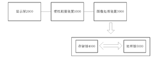
- Figure 1 is a block diagram of the composition and structure of an electronic device according to an embodiment of the present application.
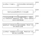
- Fig. 2 is a schematic flowchart of an image processing method according to an embodiment of the present application
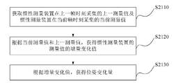
- FIG. 3 is a schematic flowchart of an image processing method according to another embodiment of the present application.
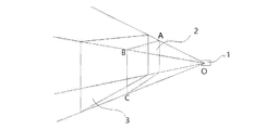
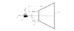
- Fig. 4 is a schematic diagram of a virtual scene of an electronic device according to an embodiment of the present application.
- FIG. 5 is a schematic diagram of the near viewport distance of a virtual scene according to an embodiment of the present application
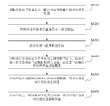
- FIG. 6 is a schematic flowchart of an image processing method according to a fourth embodiment of the present application
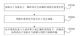
- Fig. 7 is a schematic flowchart of an image processing method according to a fifth embodiment of the present application.
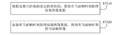
- FIG. 8 is a schematic flowchart of an image processing method according to a sixth embodiment of the present application.
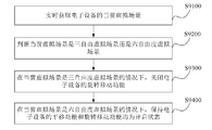
- FIG. 9 is a schematic flowchart of an image processing method according to a seventh embodiment of the present application.
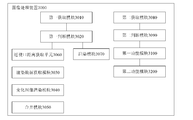
- Fig. 10 is a schematic block diagram of an image processing device according to an embodiment of the present application.
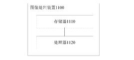
- Fig. 11 is a schematic block diagram of an image processing device according to another embodiment of the present application.
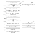
- Fig. 12 is a schematic flowchart of an image processing method according to an example of the present application.
- Fig. 1 is a structural block diagram of an electronic device according to an embodiment of the present application.
- the electronic device of the embodiment of the present application may include an inertial measurement device 1000, a display screen 2000, and an image processing device 3000.
- the inertial measurement device 1000 may be used to measure the position and attitude changes of the electronic device
- the display screen 2000 may be used to display Each frame of image at each frame time obtained by the image processing device, wherein the image processing device 3000 can process the current frame image of the electronic device at the current frame time according to the method of the embodiment of the present application.
- the electronic device may be a smart device such as a virtual reality (VR) device, an augmented reality (Augmented Reality, AR) device, or a mixed reality (Mixed Reality) device.
- VR virtual reality
- AR Augmented Reality
- Mixed Reality Mixed reality
- the inertial measurement device 1000 is also called an inertial measurement unit (IMU, Inertial Measurement Unit).
- the inertial measurement unit is an electronic device that uses a combination of sensors to measure and report speed, direction, and gravity.
- the sensors include acceleration sensors and gyroscope sensors. And geomagnetic sensor. Since the inertial measurement unit is equipped with an accelerometer that can measure three degrees of freedom, a gyroscope that can measure three degrees of freedom, and a magnetometer that can measure three degrees of freedom, the inertial measurement device 1000 is also called a nine-axis sensor.
- the degree of freedom is related to the movement of a rigid body in space, and can be interpreted as "different basic ways of object movement".
- translational motion means that a rigid body can translate in three degrees of freedom, specifically forward/backward, up/down, and left/right translational motion.
- Rotational motion means that a rigid body can rotate in three degrees of freedom, specifically pitch (Pitch), roll (Roll) and roll (Yaw).
- the virtual scene of the electronic device may include a three-degree-of-freedom virtual scene and a six-degree-of-freedom virtual scene.
- the image processing device 3000 may include one or more memories 4000 and one or more processors 5000.
- the memory 4000 may include, for example, ROM (Read Only Memory), RAM (Random Access Memory), non-volatile memory such as a hard disk, and the like.
- ROM Read Only Memory
- RAM Random Access Memory
- non-volatile memory such as a hard disk, and the like.
- the processor 5000 may be a mobile processor or a single-chip microcomputer.
- the memory 4000 is used to store instructions, and the instructions are used to control the processor 5000 to operate to execute the signal processing method according to the embodiments of the present application.
- Those skilled in the art can design instructions according to the technical solutions disclosed in the present application. How the instructions control the processor to operate is well known in the art, so the embodiments of the present application will not be described in detail here.
- Fig. 2 is a schematic flowchart of an image processing method according to an embodiment of the present application.
- the image processing method of the electronic device of this embodiment is implemented by the image processing device 3000, and the image processing method may include the following steps S2100 to S2300:
- step S2100 the image processing device 3000 obtains the amount of change in the position and posture of the electronic device from the last frame time to the current frame time.
- the electronic device includes an inertial measurement device 1000, which is an electronic device that measures and reports speed, direction, and gravity through a combination of sensors, where the sensors include acceleration sensors, gyroscope sensors, and Geomagnetic sensor.
- the inertial measurement device 1000 can measure the pose of the VR headset in real time, that is, the inertial measurement device 1000 collects the last frame at the time of the previous frame. The measured value and the current measured value collected at the current frame time.
- the step S2100 acquiring the position and posture change of the electronic device from the last frame time to the current frame time may further include the following steps S2110 to S2130:
- step S2110 the image processing device 3000 obtains the last measurement value collected by the inertial measurement device 1000 at the last frame time and the current measurement value collected by the inertial measurement device 1000 at the current frame time.
- the measurement value of the inertial measurement device 1000 includes a velocity measurement value, a direction measurement value, and a gravity measurement value.
- the inertial measurement device 1000 The measured value of is a coordinate matrix including speed measurement, direction measurement and gravity measurement.
- the image processing device 3000 acquires the position and attitude change information of the electronic equipment, that is, the image processing device 3000 acquires the last measurement value collected by the inertial measurement device 1000 at the previous frame time and the current measurement value collected by the inertial measurement device 1000 at the current frame time.
- step S2120 the image processing device 3000 obtains the incremental change value of the measurement value of the inertial measurement device according to the current measurement value and the previous measurement value.
- the moving coordinate corresponding to the virtual scene camera of the electronic device is the incremental change value of the measurement value obtained by the inertial measurement device 1000 according to the current measurement value and the previous measurement value.
- step S2130 the image processing device 3000 obtains the amount of pose change according to the incremental change value.
- the measurement value of the inertial measurement device 1000 includes a speed measurement value, a direction measurement value, and a gravity measurement value
- the measurement value of the inertial measurement device 1000 includes coordinates including a speed measurement value, a direction measurement value, and a gravity measurement value.
- Matrix, the incremental change value of the measurement value obtained by the inertial measurement device 1000 according to the current measurement value and the previous measurement value is a coordinate matrix
- the value obtained according to the coordinate matrix can represent the position and attitude change of the electronic device. This embodiment is based on the inertia
- the incremental change value of the measurement value of the measurement device 1000 can obtain the position and posture change of the electronic device.
- step S2200 the image processing device 3000 determines whether the amount of pose change is less than a set threshold.
- the electronic device when the wearer's head movement amplitude is small, that is, the position and posture change of the electronic device is less than the set threshold, the electronic device will respond to each frame of the virtual scene when it moves.
- the entire screen is re-rendered, and the amount of rendering data is large, which may easily cause delays in the rendering of the virtual scene, cause the position of the electronic device to jitter, and affect the user experience.
- This embodiment determines whether each frame of the virtual scene needs to be re-rendered as a whole by judging whether the change of the electronic device's pose is less than a set threshold, so as to avoid changing the virtual scene when the change of the electronic device's pose is small.
- the overall re-rendering of each frame of the picture causes the problem of delay in rendering of the virtual scene.
- step S2300 the image processing device 3000 obtains the image data to be rendered at the current frame time according to the current value of the near-viewport distance in the current frame time when the pose change is less than the set threshold, where the current value is greater than The initial value of the setting.
- the near viewport distance is the distance between the starting position of the image data to be rendered at the corresponding frame time and the virtual camera from the image data collected by the virtual camera in each frame time in the virtual scene.
- FIG. 4 shows a schematic diagram of a virtual scene of the electronic device of this embodiment.
- the field of view (Field of View, FOV for short) represents the display
- ⁇ AOB is the horizontal field of view
- ⁇ BOC is the vertical field of view.
- the horizontal angle of view is the range from the limit of observation to the left to the limit of observation to the right when the virtual camera 1 in the virtual scene does not rotate.
- the vertical field of view is the range from the limit of upward observation to the limit of downward observation when the virtual camera 1 in the virtual scene does not rotate.
- the field of view of a VR head-mounted display usually refers to the horizontal field of view.
- the viewing frustum refers to an area in space, which determines the space that the virtual camera can see.
- the viewing cone is surrounded by six planes, which are also called clip planes.
- the near viewport 2 and the far viewport 3 are also called a near clipping plane (near clipping plane) and a far clipping plane (far clipping plane), respectively, and the near clipping plane and the far clipping plane determine the depth range that the electronic device can see.
- FIG. 5 shows a schematic diagram of the near view port distance of the virtual scene in this embodiment.
- the near view port distance represents the distance from the virtual camera 1 to the near view port 2 (near clipping plane).
- the initial setting value of the near vision port distance is an empirical value determined according to the field angle and interpupillary distance of the human eye. The initial setting value of the near vision port distance can ensure that the screen of the electronic device falls on the display screen of the electronic device.
- the initial set value of the distance is the minimum value, that is, the shortest distance between the near-view port 2 and the virtual camera 1, and images with the near-view port distance less than the initial value cannot be displayed completely on the display screen.
- the amount of rendering data of the image displayed by the virtual camera is the data of the scene model contained in the frustum space, that is, the data of the scene model contained in the space between the near viewport and the far viewport.
- the data of the image displayed at the near-viewport is generated, that is, the image data to be rendered at the current frame time is the near-viewport distance as the current value
- the space between the near viewport and the far viewport contains data of the scene model, where the current value is greater than the set initial value.
- the image data to be rendered at the current frame time represents the data required to generate the changed part of the image at the current frame time and the image of the previous frame.
- This embodiment determines the image data to be rendered at the current frame time by setting the near-viewport distance at the current frame time, and according to the current value of the near-viewport distance at the current frame time, reduces the amount of rendering data at the current frame time, and shortens the call of rendering data Time, avoid the display screen delay caused by the large amount of rendering data, thereby eliminating the jitter of the electronic device and improving the user experience.
- step S2400 the image processing device 3000 renders the image data to be rendered at the current frame time to obtain the changed image at the current frame time.
- the image data to be rendered at the current frame time is the rendering data of the image displayed at the near view port when the near view port distance is the current value, and the image displayed at the near view port at the current frame time is rendered to obtain The changing image at the current frame moment.
- step S2500 the image processing device 3000 combines the last frame image and the changed image to obtain the current frame image at the current frame moment.
- merging the last frame image and the changed image is to align the center point of the changed image with the center point of the previous frame image, and replace the center part of the previous frame image by the changed image to obtain the corresponding current frame time The current frame image.
- the last frame of image is the image displayed at the near vision port corresponding to the distance of the near vision port at the last frame time rendered in the last frame time. Based on the position and attitude change of the electronic device, the image is within the set threshold. The user’s angle of view will not observe changes in the outer image.
- the distance of the near vision port at the current frame time is set to the current value, and the current value is less than the initial setting value.
- the current frame time is obtained
- the changed image is merged with the previous frame image rendered at the last frame time to obtain the current image at the current frame time, thereby reducing the amount of rendering data at the current frame time, shortening the rendering data call time, and avoiding rendering
- the display picture delay caused by the large amount of data eliminates the jitter of electronic equipment and improves the user experience.
- the position and posture change of the electronic device moving to the position of the last frame time is greater than or equal to the set threshold
- the near vision port distance of the virtual camera of the electronic device at the last frame time is the initial set value
- the image displayed at the near view port at one frame time is the image with the near view port distance as the initial setting value
- the current frame image at the current frame time is the combination of the previous frame image rendered at the previous frame time and the changed image rendered at the current frame After merging, it is equivalent to that the previous frame of image supplements the missing picture of the changed image rendered in the current frame, that is, the amount of data of the merged current frame image and the image whose near-viewport distance is the initial setting value is equivalent.
- the position and attitude change of the electronic device at the time of the previous frame is less than the set threshold, and the distance of the near vision port of the virtual camera of the electronic device at the time of the previous frame is the setting corresponding to the time of the previous frame.
- the setting value is less than the initial setting value.
- the image displayed at the near vision port at the last frame time is the image whose near vision port distance is the setting value corresponding to the last frame time, and the last frame image is the last frame rendering
- the image obtained after merging the image of the previous frame with the image of the previous frame is the image equivalent to the image displayed at the near-view port whose distance to the near-view port is the initial set value.
- the current frame image at the current frame time is obtained by combining the previous frame image rendered at the previous frame time and the changed image rendered by the current frame.
- the combined image is equivalent to the previous frame image supplementing the missing image of the current frame rendering.
- the picture, that is, the current frame image obtained by the merge has the same amount of data as the image whose near-viewport distance is the initial setting value.
- the pose change of the electronic device when the pose change of the electronic device is less than the set threshold, based on setting the current value greater than the initial value of the near vision port distance, according to the current value of the near vision port distance at the current frame time, determine the waiting time of the current frame time. Rendered image data, based on the image data to be rendered at the current frame time, obtain the changed image at the current frame time, merge the changed image with the previous frame image rendered at the last frame time, and obtain the current image at the current frame time, thereby reducing The amount of rendering data at the current frame time shortens the call time of rendering data, avoids the display screen delay caused by the large amount of rendering data, thereby eliminating the jitter of electronic devices and improving user experience.
- step S6300 adds step S6300 to the embodiment shown in FIG. 4.
- the method may include the following steps: S6100-S6500.
- Step S6100 the image processing device 3000 obtains the amount of change in the position and posture of the electronic device from the last frame time to the current frame time;
- Step S6200 judging whether the amount of change in pose is less than a set threshold
- step S6300 the image processing device 3000 obtains the current value of the near-viewport distance according to the amount of pose change.
- the amount of rendering data of the image displayed at the near view port is equivalent to the data of the scene model contained in the space between the near view port and the far view port.
- the current value of the near vision port distance may be a preset fixed value, and the fixed value is smaller than the initial value.
- the current value of the near-viewport distance can be determined according to the amount of pose change, for example, the smaller the pose change, the larger the current value, and the smaller the amount of data that needs to be rendered.
- Step S6400 Render the image data to be rendered at the current frame time to obtain the changed image at the current frame time.
- Step S6500 Combine the previous frame image and the changed image to obtain the current frame image at the current frame moment.
- the image processing method of the electronic device in the embodiment of the present application may further include the following steps S7100 to S7300:
- step S7100 the image processing device 3000 obtains the position and posture change of the electronic device from the last frame time to the current frame time.
- step S7200 the image processing device 3000 determines whether the amount of pose change is less than a set threshold.
- step S7300 the image processing device 3000 directly renders the current frame image of the electronic device at the current frame time when the pose change is greater than or equal to the set threshold.
- directly rendering to obtain the current frame image of the electronic device at the current frame time may further include the following step S7310 ⁇ S7320:
- step S7310 the image processing device 3000 obtains the image data to be rendered at the current frame time according to the set initial value of the near-viewport distance, where the initial value is the minimum value of the near-viewport distance.
- the near-viewport distance is the distance between the starting position of the image data to be rendered at the corresponding frame time and the virtual camera from the image data collected by the virtual camera in the virtual scene at the corresponding frame time.
- step S7320 the image processing device 3000 renders the image data to be rendered at the current frame time to obtain the current frame image at the current frame time.
- the near vision port distance is the distance between the near vision port and the virtual camera of the virtual scene
- the initial setting value of the near vision port distance is an empirical value
- the initial setting value of the near vision port distance is based on the human eye
- the field angle and interpupillary distance are determined to ensure that the screen of the electronic device falls on the display screen of the electronic device. Therefore, the initial setting value of the near-viewport distance is the minimum value, that is, the closest distance to the virtual camera.
- the image processing method of the electronic device in the embodiment of the present application may further include the following steps S9100 to S9400 before acquiring the position and attitude change of the electronic device from the last frame time to the current frame time:
- Step S9100 The image processing device 3000 acquires the current virtual scene of the electronic device in real time.
- Step S9200 the image processing device 3000 determines whether the current virtual scene is a three-free virtual scene or a six-degree-of-freedom virtual scene
- step S9300 the image processing device 3000 turns off the rotation movement function of the electronic device when the current virtual scene is a three-degree-of-freedom virtual scene.
- step S9400 when the current virtual scene is a six-degree-of-freedom virtual scene, the image processing device 3000 keeps both the translation function and the rotation movement function of the electronic device in an on state.
- the virtual scene of the electronic device may include a three-degree-of-freedom virtual scene and a six-degree-of-freedom virtual scene.
- the motion of the electronic device includes only translational motion but not rotational motion, that is, the electronic device can translate in three degrees of freedom, specifically forward/backward, up/down, and leftward / Pan movement to the right.
- the rotation and movement function of the electronic device is turned off, that is, the spatial displacement function of the virtual camera in the virtual scene is turned off, and only the three-degree-of-freedom angle change function is retained, which can further avoid the spatial position movement The impact of jitter.
- the current frame time can be determined based on the current value greater than the initial value of the near-viewport distance when the pose change of the electronic device is less than the set threshold. Based on the to-be-rendered image data at the current frame time, the changed image at the current frame time is obtained, and the changed image is merged with the previous frame image rendered at the last frame time to obtain the current image at the current frame time. Reduce the amount of rendering data at the current frame time, shorten the call time of rendering data, and avoid the display screen delay caused by the large amount of rendering data, thereby eliminating the jitter of electronic devices and improving user experience.
- Fig. 10 is a schematic block diagram of an image processing device according to an embodiment of the present application.
- the image processing device 3000 may include a first acquisition module 3010, a first judgment module 3020, a rendering data acquisition module 3030, a changed image rendering module 3040, and a merging module 3050 for Implementation of the image processing method provided in this embodiment will not be repeated here.
- the first acquisition module 3010 can acquire the position and posture change of the electronic device from the last frame time to the current frame time.
- the first judging module 3020 can be used to judge whether the change in pose is less than a set threshold.
- the rendering data acquisition module 3030 can be used to acquire the image data to be rendered at the current frame time according to the current value of the near-viewport distance at the current frame time when the pose change amount is less than the set threshold.
- the myopia distance is the distance between the starting position of the image data to be rendered at the corresponding frame time and the virtual camera from the image data collected by the virtual camera in the virtual scene at each frame time.
- the current value is greater than the set initial value .
- the changed image rendering module 3040 may be used to render the image data to be rendered at the current frame time to obtain the changed image at the current frame time.
- the merging module 3050 can be used to merge the previous frame image and the changed image to obtain the current frame image at the current frame moment.
- the merging module 3050 can also be used to align the center point of the changed image with the center point of the previous frame image, and replace the central part of the previous frame image by the changed image to obtain the corresponding current frame time The current frame image.
- the first acquisition module 3010 may include a measurement unit 3011, an incremental change value determination unit 3012, and a pose change amount acquisition unit 3013.
- the measurement unit 3011 may be used to obtain the last measurement value collected by the inertial measurement device at the last frame time and the current measurement value collected by the inertial measurement device at the current frame time.
- the incremental change value determining unit 3012 may be used to obtain the incremental change value of the measurement value of the inertial measurement device according to the current measurement value and the previous measurement value.
- the pose change acquisition unit 3013 may be used to obtain the pose change according to the incremental change value.
- the image processing device 3000 may further include a near vision port distance acquiring unit 3060.
- the near-viewport distance obtaining unit 3060 may be used to obtain the current value of the near-viewport distance according to the amount of pose change.
- the image processing device 3000 may further include a rendering module 3070.
- the rendering module 3070 may be used to directly render the current frame image of the electronic device at the current frame time when the pose change amount is greater than or equal to the set threshold.
- the rendering module 3070 may include a data acquisition unit 3071 and a rendering unit 3072.
- the data acquiring unit 3071 may be used to acquire the image data to be rendered at the current frame time according to the initial value of the near-viewport distance setting.
- the near view port distance is the distance between the starting position of the image data to be rendered at the corresponding frame time and the virtual camera from the image data collected by the virtual camera in the virtual scene at the corresponding frame time
- the initial value is the minimum near view port distance value
- the rendering unit 3720 may be used to render the image data to be rendered at the current frame time to obtain the current frame image at the current frame time.
- the image processing device 3000 may further include a second acquisition module 3080, a second judgment module 3090, a first function module 3100, and a second function module 3200.
- the second acquisition module 3080 may be used to acquire the current virtual scene of the electronic device in real time.
- the second judgment model 3090 can be used to judge whether the current virtual scene is a three-free virtual scene or a six-degree-of-freedom virtual scene.
- the first function module 3100 may be used to turn off the rotation and movement function of the electronic device when the current virtual scene is the three-degree-of-freedom virtual scene.
- the second function module 3200 may be used to maintain the translation function and the rotation movement function of the electronic device in an on state when the current virtual scene is the six-degree-of-freedom virtual scene.
- FIG. 11 another image processing apparatus 1100 for electronic equipment is also provided, as shown in FIG. 11, including:
- the memory 1110 is used to store executable instructions
- the processor 1120 is configured to run an electronic device to execute the image processing method provided in this embodiment according to the control of the executable instruction.
- the image processing device 1100 may be a virtual reality (VR) device, an augmented reality (Augmented Reality, AR) device, or a mixed reality (Mixed Reality) device and other smart devices with image processing. Module.
- VR virtual reality
- AR Augmented Reality
- Mixed Reality Mixed reality
- an electronic device is further provided, and the electronic device includes:
- the inertial measurement device 1000 can be used to measure the pose change of a virtual device.
- the inertial measurement device 1000 is also called an inertial measurement unit (IMU, Inertial Measurement Unit), which is an electronic device that measures and reports speed, direction, and gravity through a combination of sensors.
- IMU Inertial Measurement Unit
- the display screen 2000 may be used to display each frame of image at each frame time obtained by the image processing device.
- the display screen 2000 may be a mobile phone.
- the image processing apparatus 3000 may be as shown in FIG. 10, and the image processing apparatus 1100 may be as shown in FIG. 11, which will not be repeated here.
- the electronic device may be an intelligent device having a virtual reality (VR) device, an augmented reality (Augmented Reality, AR) device, or a mixed reality (Mixed Reality) device.
- the image processing apparatus 1100 may be a module with an image processing function in an electronic device.
- the chip of the electronic device directly executes the image processing method corresponding to this embodiment, and details are not described herein again.
- FIG. 12 is a schematic flowchart of an image processing method according to an example of the present application.
- the image processing method may include the following steps:
- step S12001 the image processing device 3000 acquires the current virtual scene of the electronic device in real time.
- step S12002 the image processing device 3000 determines whether the current virtual scene conforms to the three-free virtual scene, and if the current virtual scene conforms to the three-free virtual scene, step S12003 is executed, otherwise, step S12004 is executed.
- Step S12003 turn off the rotational movement function of the electronic device, and then execute step S12005.
- step S12004 keeping both the translation function and the rotational movement function of the electronic device in an on state, and then step S12005 is executed.
- step S12005 the image processing device 3000 obtains the last measurement value collected by the inertial measurement device 1000 at the last frame time and the current measurement value collected by the inertial measurement device 1000 at the current frame time.
- step S12006 the image processing device 3000 obtains the incremental change value of the measurement value of the inertial measurement device according to the current measurement value and the previous measurement value.
- step S12007 the image processing device 3000 obtains the amount of pose change according to the incremental change value.
- step S12008 the image processing device 3000 determines whether the amount of change in pose is less than the set threshold, if it is determined that the amount of change in pose is less than the set threshold, step S12009 is executed, otherwise, step S12040 is executed.
- step S12009 the current value of the near vision port distance is obtained according to the amount of pose change.
- step S12010 the image processing device 3000 obtains the image data to be rendered at the current frame time according to the current value of the near-viewport distance at the current frame time.
- step S12020 the image processing device 3000 renders the image data to be rendered at the current frame time to obtain the changed image at the current frame time.
- step S12030 the image processing device 3000 combines the last frame image and the changed image to obtain the current frame image at the current frame moment.
- step S12040 the image data to be rendered at the current frame time is obtained according to the set initial value of the near-viewport distance.
- step S12050 the image processing device 3000 renders the image data to be rendered at the current frame time to obtain the current frame image at the current frame time.
- the steps of the method or algorithm described in the embodiments disclosed in this document can be directly implemented by hardware, a software module executed by a processor, or a combination of the two.
- the software module can be placed in random access memory (RAM), internal memory, read-only memory (ROM), electrically programmable ROM, electrically erasable programmable ROM, registers, hard disks, removable disks, CD-ROMs, or all areas in the technical field. Any other known storage medium.
Landscapes
- Engineering & Computer Science (AREA)
- Theoretical Computer Science (AREA)
- Physics & Mathematics (AREA)
- General Physics & Mathematics (AREA)
- General Engineering & Computer Science (AREA)
- Computer Hardware Design (AREA)
- Human Computer Interaction (AREA)
- Computer Vision & Pattern Recognition (AREA)
- Signal Processing (AREA)
- Multimedia (AREA)
- Architecture (AREA)
- Computer Graphics (AREA)
- Software Systems (AREA)
- Processing Or Creating Images (AREA)
- User Interface Of Digital Computer (AREA)
Abstract
本申请公开了一种用于电子设备的图像处理方法、装置及电子设备,该方法包括:获取电子设备从上一帧时刻至当前帧时刻的位姿变化量;判断位姿变化量是否小于设定阈值;在位姿变化量小于设定阈值的情况下,根据近视口距离在当前帧时刻的当前值,获取在当前帧时刻的待渲染图像数据;渲染在当前帧时刻的待渲染图像数据,得到在当前帧时刻的变化图像;合并上一帧图像和所述变化图像,得到在当前帧时刻的当前帧图像。
Description
本申请要求于2019年6月13日提交中国专利局、申请号为201910510610.9、申请名称为“用于电子设备的图像处理方法、装置及电子设备”的中国专利申请的优先权,其全部内容通过引用结合在本申请中。
本申请涉及电子设备的图像显示技术领域,更具体地,本申请涉及一种用于电子设备的图像处理方法、装置及电子设备。
随着VR、AR或者MR电子设备的普及,越来越多的人群加入到虚拟现实体验的阵营中。在虚拟世界中,用户可以玩游戏、直播、观看视频,其中这些项目的体验都需要稳定的帧率和画面显示效果,如果显示画面不稳定,效果达不到预期,很容易给用户的身体造成不良影响,降低用户的体验,从而造成用户的流失。
但目前的电子设备存在一些问题,以VR设备为头戴虚拟现实设备为例,当佩戴者头部运动幅度较小时,移动时电子设备对虚拟场景的每一帧画面整体重新渲染,渲染数据量较大,容易造成虚拟场景渲染延迟,引起电子设备位置抖动,影响用户体验。
发明内容
本申请实施例的一个目的是提供一种用于电子设备的图像处理方案。
根据本申请的第一方面,提供了一种用于电子设备的图像处理方法,其包括:
获取所述电子设备从上一帧时刻至当前帧时刻的位姿变化量;
判断所述位姿变化量是否小于设定阈值;
在所述位姿变化量小于所述设定阈值的情况下,根据近视口距离在所述当前帧时刻的当前值,获取在当前帧时刻的待渲染图像数据,所述当前值大于设定的初始值;其中,所述近视口距离为虚拟场景中的虚拟相机在每一帧时刻采集的图像数据中提取在对应帧时刻的待渲染图像数据的起始位置与所述虚拟相机的距离;
渲染所述在当前帧时刻的待渲染图像数据,得到在当前帧时刻的变化图像;
合并所述上一帧图像和所述变化图像,得到所述在当前帧时刻的当前帧图像。
可选地,所述在当前帧时刻的待渲染图像数据为生成当前帧时刻的图像与上一帧图像的变化的部分所需的数据。
可选地,所述获取在当前帧时刻的待渲染图像数据之前,所述图像处理方法还包括:
根据所述位姿变化量,获得所述近视口距离的所述当前值。
可选地,合并所述上一帧图像和所述变化图像,得到所述在当前帧时刻的当前帧图像,包括:
将所述变化图像的中心点与所述上一帧图像的中心点对齐,通过所述变化图像替换所述上一帧图像的中央部分,得到对应当前帧时刻的当前帧图像。
可选地,所述图像处理方法还包括:
在所述位姿变化量大于或者等于所述设定阈值的情况下,直接渲染得到所述电子设备在当前帧时刻的当前帧图像。
可选地,所述直接渲染得到所述电子设备在当前帧时刻的当前帧图像,包括:
根据近视口距离的设定的初始值,获取在当前帧时刻的待渲染图像数据,所述初始值为所述近视口距离的最小值;其中,所述近视口距离为从虚拟场景中的虚拟相机在对应帧时刻采集的图像数据中获取在对应帧时刻的待渲染图像数据的起始位置与所述虚拟相机的距离;
渲染所述在当前帧时刻的待渲染图像数据,得到所述在当前帧时刻的当前帧图像。
可选地,所述电子设备还包括惯性测量装置,所述获取所述电子设备从上一帧时刻至当前帧时刻的位姿变化量,包括:
获取所述惯性测量装置在所述上一帧时刻采集的上一测量值及所述惯性测量装置在所述当前帧时刻采集的当前测量值;
根据所述当前测量值和所述上一测量值,获得所述惯性测量装置的测量值的增量变化值;
根据所述增量变化值,获得所述位姿变化量。
可选地,所述获取所述电子设备从上一帧时刻至当前帧时刻的位姿变化量之前,所述的图像处理方法还包括:
实时获取所述电子设备的当前虚拟场景;
判断所述当前虚拟场景是三自由虚拟场景还是六自由度虚拟场景;
在所述当前虚拟场景是所述三自由度虚拟场景的情况下,关闭所述电子设备的旋转移动功能;
在所述当前虚拟场景是所述六自由度虚拟场景的情况下,保持所述电子设备的平移功能和旋转移动功能均为开启状态。
根据本申请的第二方面,提供了一种用于电子设备的图像处理装置,其包括:
第一获取模块,用于获取所述电子设备从上一帧时刻至当前帧时刻的位姿变化量;
第一判断模块,用于判断所述位姿变化量是否小于设定阈值;
渲染数据获取模块,用于在所述位姿变化量小于所述设定阈值的情况下,根据近视口距离在所述当前帧时刻的当前值,获取在当前帧时刻的待渲染图像数据,其中,所述近视口距离为虚拟场景中的虚拟相机在每一帧时刻采集的图像数据中提取在对应帧时刻的待渲染图像数据的起始位置与所述虚拟相机的距离,所述当前值大于设定的初始值;
变化图像渲染模块,渲染所述在当前帧时刻的待渲染图像数据,得到在当前帧时刻的变化图像;
合并模块,合并所述上一帧图像和所述变化图像,得到所述在当前帧时刻的当前帧图像。
根据本申请的第三方面,提供了一种用于电子设备的图像处理装置,其包括存储器和处理器,所述存储器用于存储计算机指令,所述处理器用于从所述存储器中调用所述计算机指令,并在所述计算机指令的控制下执行如第一方面中任一项所述的图像处理方法。
根据本申请的第四方面,提供了一种电子设备,其包括惯性测量装置、显示屏以及如第二方面中任一项所述的图像处理装置,所述显示屏用于显示所述图像处理装置得到的每一帧时刻的每一帧图像。
根据本申请公开的一个实施例,可以针对电子设备的位姿变化量小于设定阈值的情况下,基于设定大于近视口距离初始值的当前值,根据当前帧时刻近视口距离的当前值,确定当前帧时刻的待渲染图像数据,基于当前帧时刻的待渲染图像数据,获得当前帧时刻的变化图像,将变化图像与上一帧时刻渲染过的上一帧图像合并,获得当前帧时刻的当前图像,从而减小当前帧时刻的渲染数据量,缩短渲染数据的调用时间,避免由于渲染数据量大造成的显示画面延迟,从而消除电子设备的抖动,提高用户体验。
通过以下参照附图对本申请的示例性实施例的详细描述,本申请的其它特征及其优点将会变得清楚。
为了更清楚地说明本申请实施例或现有技术中的技术方案,下面将对实施例或现有技术描述中所需要使用的附图作简单地介绍,显而易见地,下面描述中的附图仅仅是本申请的一部分附图,对于本领域普通技术人员来讲,在不付出创造性劳动的前提下,还可以根据提供的附图获得其他的附图。
图1是根据本申请实施例的电子设备的组成结构框图;
图2是根据本申请实施例的图像处理方法的示意性流程图;
图3是根据本申请另一实施例的图像处理方法的示意性流程图;
图4是根据本申请实施例的电子设备的虚拟场景的示意图;
图5是根据本申请实施例的虚拟场景近视口距离的示意图;图6是根据本申请第四实施例的图像处理方法的示意性流程图;
图7是根据本申请第五实施例的图像处理方法的示意性流程图;
图8是根据本申请第六实施例的图像处理方法的示意性流程图;
图9是根据本申请第七实施例的图像处理方法的示意性流程图;
图10是根据本申请实施例的图像处理装置的示意性原理框图;
图11是根据本申请另一个实施例的图像处理装置的示意性原理框图;
图12是根据本申请一个例子的图像处理方法的流程示意图。
下面将结合本申请实施例中的附图,对本申请实施例中的技术方案进行描述,显然,所描述的实施例仅仅是本申请一部分实施例,而不是全部的实施例。基于本申请中的实施例,本领域普通技术人员在没有做出创造性劳动前提下所获得的所有其他实施例,都属于本申请保护的范围。
对于相关领域普通技术人员已知的技术、方法和设备可能不作详细讨论,但在适当情况下,所述技术、方法和设备应当被视为说明书的一部分。
在这里示出和讨论的所有例子中,任何具体值应被解释为仅仅是示例性的,而不是作为限制。因此,示例性实施例的其它例子可以具有不同的值。
应注意到:相似的标号和字母在下面的附图中表示类似项,因此,一旦某一项在一个附图中被定义,则在随后的附图中不需要对其进行进一步讨论。
<硬件配置>
图1是根据本申请实施例的电子设备的组成结构框图。
根据图1所示,本申请实施例电子设备可以包括惯性测量装置1000、显示屏2000和图像处理装置3000,惯性测量装置1000可以用于测量电子设备的位姿变化,显示屏2000可以用于显示图像处理装置得到的每一帧时刻的每一帧图像,其中,图像处理装置3000可以根据本申请实施例的方法对电子设备在当前帧时刻的当前帧图像进行处理。
本申请的实施例中,电子设备可以是虚拟现实(Virtual Reality,VR)设备、增强现实(Augmented Reality,AR)设备或者混合现实(Mixed Reality)设备等智能设备。
惯性测量装置1000又称为惯性测量单元(IMU,Inertial Measurement Unit),惯性测量单元是一种通过传感器组合来测量和报告速度、方向和重力的电子设备,其中,传感器包括加速度传感器、陀螺仪传感器和地磁 传感器。由于惯性测量单元搭载了一个可以测量三自由度的加速度计,一个能测量三自由度的陀螺仪,以及一个能测量三自由度的磁力计,因此,惯性测量装置1000也称为九轴传感器。
本申请的实施例中,自由度(DoF)与刚体在空间内的运动相关,可以解释为“物体移动的不同基本方式”。自由度总共有六个,可分成两种不同的类型:平移和旋转。平移运动表示刚体可以在三个自由度中平移,具体为向前/向后、向上/向下、向左/向右平移运动。旋转运动表示刚体可以在三个自由度中旋转,具体为纵摇(Pitch)、横摇(Roll)和垂摇(Yaw)。根据电子设备的空间运动状态,电子设备的虚拟场景可以包括三自由度虚拟场景和六自由度虚拟场景。
在本申请的实施例中,参照图1所示,图像处理装置3000可以包括一个或多个存储器4000和一个或多个处理器5000。
存储器4000例如可以包括ROM(只读存储器)、RAM(随机存取存储器)、诸如硬盘的非易失性存储器等。
处理器5000可以是移动版处理器,也可以是单片机等。
存储器4000用于存储指令,该指令用于控制处理器5000进行操作以执行根据本申请实施例的信号处理方法,本领域技术人员可以根据本申请所公开的技术方案设计指令。指令是如何控制处理器进行操作,这是本领域的公知,故本申请实施例在此不再详细描述。
<方法实施例>
图2根据本申请实施例的图像处理方法的示意性流程图。
根据图2所示,本实施例的电子设备的图像处理方法由图像处理装置3000实施,该图像处理方法可以包括如下步骤S2100~S2300:
步骤S2100,图像处理装置3000获取电子设备从上一帧时刻至当前帧时刻的位姿变化量。
在本申请的实施例中,电子设备包括惯性测量装置1000,惯性测量装置1000是一种通过传感器组合来测量和报告速度、方向和重力的电子设备,其中,传感器包括加速度传感器、陀螺仪传感器和地磁传感器。例如,佩戴者使用VR头戴设备时,当佩戴者头部运动时,惯性测量装置1000可以对VR头戴设备的位姿进行实时测量,即惯性测量装置1000在上一帧时刻采集的上一测量值及在当前帧时刻采集的当前测量值。
根据图3所示,在本申请的实施例中,该步骤S2100获取电子设备从上一帧时刻至当前帧时刻的位姿变化量可以进一步包括如下步骤S2110~S2130:
步骤S2110,图像处理装置3000获取惯性测量装置1000在上一帧时刻采集的上一测量值及惯性测量装置1000在当前帧时刻采集的当前测量值。
在本申请的实施例中,由于惯性测量装置1000包括加速度传感器、陀螺仪传感器和地磁传感器,因此,惯性测量装置1000的测量值包括速度测量值、方向测量值和重力测量值,惯性测量装置1000的测量值为包括速度测量值、方向测量值和重力测量值的坐标矩阵。
电子设备的位置发生变化时,电子设备的虚拟场景camera随电子设备同步移动,从而虚拟场景随之变化,虚拟场景变化前的时刻为上一帧时刻,虚拟场景变化后的时刻为当前帧时刻,图像处理装置3000获取电子设备的位姿变化信息,即图像处理装置3000获取惯性测量装置1000在上一帧时刻采集的上一测量值及惯性测量装置1000在当前帧时刻采集的当前测量值。
步骤S2120,图像处理装置3000根据当前测量值和上一测量值,获得惯性测量装置的测量值的增量变化值。
在本申请的实施例中,电子设备的位置发生变化时,电子设备的虚拟场景camera对应的移动坐标是惯性测量装置1000根据当前测量值和上一测量值获得的测量值的增量变化值。
步骤S2130,图像处理装置3000根据增量变化值,获得位姿变化量。
在本申请的实施例中,惯性测量装置1000的测量值包括速度测量值、方向测量值和重力测量值,惯性测量装置1000的测量值为包括速度测量值、方向测量值和重力测量值的坐标矩阵,惯性测量装置1000根据当前测量值和上一测量值获得的测量值的增量变化值为坐标矩阵,根据该坐标矩阵求出的数值可以表征电子设备的位姿变化,本实施例根据惯性测量装置1000的测量值的增量变化值可以获得电子设备的位姿变化量。
步骤S2200,图像处理装置3000判断位姿变化量是否小于设定阈值。
在本申请的实施例中,以VR头戴设备为例,当佩戴者头部运动幅度较小时,即电子设备的位姿变化量小于设定阈值,移动时电子设备对虚拟场景的每一帧画面整体重新渲染,渲染数据量较大,容易造成虚拟场景渲染延迟,引起电子设备的位置抖动,影响用户体验。本实施例通过判断电子设备的位姿变化量是否小于设定阈值,确定判断虚拟场景的每一帧画面是否需要整体重新渲染,以避免在电子设备位姿变化量较小的情况下对虚拟场景的每一帧画面整体重新渲染造成虚拟场景渲染延迟的问题。
步骤S2300,图像处理装置3000在位姿变化量小于设定阈值的情况下,根据近视口距离在所述当前帧时刻的当前值,获取在当前帧时刻的待渲染图像数据,其中,当前值大于设定的初始值。
本实施例中,近视口距离为虚拟场景中的虚拟相机在每一帧时刻采集的图像数据中提取在对应帧时刻的待渲染图像数据的起始位置与虚拟相机的距离。
图4示出了本实施例的电子设备的虚拟场景的示意图,根据图4所示,在本申请的实施例的电子设备的显示系统中,视场角(Field of View, 简称FOV)表示显示器边缘与观察点连线的夹角,图中∠AOB是水平视场角,∠BOC是垂直视场角。水平视场角是在虚拟场景中的虚拟相机1不发生转动的情况下,向左观察的极限到向右观察的极限的范围。垂直视场角是在虚拟场景中的虚拟相机1不发生转动的情况下,向上观察的极限到向下观察的极限的范围。例如,VR头戴式显示器的视场角通常指水平视场角。
在图4中,视锥体指的是空间中的一块区域,这块区域决定了虚拟相机可以看到的空间。视锥体由六个平面包围而成,这些平面也被称为裁剪平面(clip planes)。其中,近视口2和远视口3分别又称为近裁剪平面(near clip plane)和远裁剪平面(far clip plane),近裁剪平面和远裁剪平面决定了电子设备可以看到的深度范围。
图5示出了本实施例虚拟场景近视口距离的示意图,近视口距离是表示虚拟相机1到近视口2(近裁剪平面)的距离。近视口距离的初始设定值是根据人眼的视场角和瞳距而确定的经验值,近视口距离的初始设定值可以保证电子设备的画面落在电子设备的显示屏上,近视口距离的初始设定值为最小值,即近视口2距离虚拟相机1的最近距离,小于初始值的近视口距离的图像不能在显示屏上显示完全。
在电子设备的图像处理中,虚拟相机显示的图像的渲染数据量是视锥体空间内包含场景模型的数据,即就是近视口与远视口之间的空间内包含的场景模型的数据。近视口距离越小即近视口2越靠近虚拟相机1,图片包含的信息越多,渲染数据量越大;近视口距离越大即近视口2越远离虚拟相机1,图片包含的信息越少,渲染数据量越小。
例如,当电子设备的位姿变化越小时,如果每一帧直接渲染近视口距离为初始设定值的近视口处显示的图像,由于渲染数据量大,容易造成画面延迟,引起电子设备抖动,影响用户体验。而当电子设备位姿变化越小时,远视口图像本身变化就很大。
在本实施例中,在当前帧时刻的待渲染图像数据为近视口距离为当前值时,生成近视口处显示的图像的数据,即当前帧时刻的待渲染图像数据为近视口距离为当前值时,近视口与远视口之间的空间内包含场景模型的数据,其中,当前值大于设定的初始值。在当前帧时刻的待渲染图像数据表征了生成当前帧时刻的图像与上一帧图像的变化的部分所需的数据。
本实施例通过设定当前帧时刻的近视口距离,根据当前帧时刻近视口距离的当前值,确定当前帧时刻的待渲染图像数据,减小当前帧时刻的渲染数据量,缩短渲染数据的调用时间,避免由于渲染数据量大造成的显示画面延迟,从而消除电子设备的抖动,提高用户体验。
步骤S2400,图像处理装置3000渲染在当前帧时刻的待渲染图像数据,得到在当前帧时刻的变化图像。
在本申请的实施例中,在当前帧时刻的待渲染图像数据为近视口距离为当前值时近视口处显示的图像的渲染数据,对当前帧时刻的近视口处显示的图像进行渲染,得到在当前帧时刻的变化图像。
步骤S2500,图像处理装置3000合并上一帧图像和变化图像,得到在当前帧时刻的当前帧图像。
在本实施例中,合并上一帧图像和变化图像为,将变化图像的中心点与上一帧图像的中心点对齐,通过变化图像替换上一帧图像的中央部分,得到对应当前帧时刻的当前帧图像。
其中,上一帧图像即在上一帧时刻渲染的对应上一帧时刻的近视口距离的近视口处显示的图像,基于电子设备的位姿变化量控制在设定阈值之内,图像处于近视口,用户的视角不会观察到外侧图像的变化,对当前帧时刻的近视口距离设定为当前值,当前值小于初始设定值,基于当前帧时刻的待渲染图像数据,获得当前帧时刻的变化图像,将变化图像与上一帧时刻渲染过的上一帧图像合并,获得当前帧时刻的当前图像,从而减小当前帧时刻的渲染数据量,缩短渲染数据的调用时间,避免由于渲染数据量大造成的显示画面延迟,从而消除电子设备的抖动,提高用户体验。
在本申请的一个例子中,电子设备移动到上一帧时刻的位置的位姿变化大于或者等于设定阈值,电子设备的虚拟相机在上一帧时刻的近视口距离为初始设定值,上一帧时刻的近视口处显示的图像为近视口距离为初始设定值的图像,当前帧时刻的当前帧图像为上一帧时刻渲染的上一帧图像和当前帧渲染的变化图像合并得到的,合并后相当于上一帧图像补充了当前帧渲染的变化图像缺少的画面,即合并得到的当前帧图像和近视口距离为初始设定值的图像的数据量相当。
在本申请的另一个例子中,电子设备移动到上一帧时刻的位置的位姿变化小于设定阈值,电子设备的虚拟相机在上一帧时刻的近视口距离为上一帧时刻对应的设定值,该设定值小于初始设定值,上一帧时刻的近视口处显示的图像为近视口距离为上一帧时刻对应的设定值的图像,上一帧图像为上一帧渲染的图像与之前帧图像合并后得到的图像,即与近视口距离为初始设定值的近视口处显示的图像相当的图像。因此,当前帧时刻的当前帧图像为上一帧时刻合并渲染的上一帧图像和当前帧渲染的变化图像合并得到的,合并后相当于上一帧图像补充了当前帧渲染的变化图像缺少的画面,即合并得到的当前帧图像和近视口距离为初始设定值的图像的数据量相当。
本实施例可以针对电子设备的位姿变化量小于设定阈值的情况下,基于设定大于近视口距离初始值的当前值,根据当前帧时刻近视口距离的当前值,确定当前帧时刻的待渲染图像数据,基于当前帧时刻的待渲染图像数据,获得当前帧时刻的变化图像,将变化图像与上一帧时刻渲染过的上一帧图像合并,获得当前帧时刻的当前图像,从而减小当前帧时刻的渲染 数据量,缩短渲染数据的调用时间,避免由于渲染数据量大造成的显示画面延迟,从而消除电子设备的抖动,提高用户体验。
根据图6所示,在本申请的实施例在图4所示实施例的基础上增加了步骤S6300,该方法可以包括如下步骤:S6100-S6500。
步骤S6100,图像处理装置3000获取电子设备从上一帧时刻至当前帧时刻的位姿变化量;
步骤S6200,判断位姿变化量是否小于设定阈值;
步骤S6300,图像处理装置3000根据位姿变化量,获得近视口距离的当前值。
近视口处显示的图像的渲染数据量相当于近视口与远视口之间的空间内包含的场景模型的数据,近视口距离越小即近视口越靠近虚拟相机,图片包含的信息越多,渲染数据量越大;近视口距离越大即近视口越远离虚拟相机,图片包含的信息越少,渲染数据量越小。
在位姿变化量小于设定阈值的情况下:
在本申请的一个例子中,近视口距离的当前值可以是预设的固定值,且该固定值小于初始值。
在本申请的另一个例子中,近视口距离的当前值可以根据位姿变化量确定,例如位姿变化量越小,当前值越大,需要渲染的数据量越小。
步骤S6400,渲染在当前帧时刻的待渲染图像数据,得到在当前帧时刻的变化图像。
步骤S6500,合并所述上一帧图像和所述变化图像,得到所述在当前帧时刻的当前帧图像。
根据图7所示,在本申请的实施例的电子设备的图像处理方法还可以包括如下步骤S7100~S7300:
步骤S7100,图像处理装置3000获取电子设备从上一帧时刻至当前帧时刻的位姿变化量。
步骤S7200,图像处理装置3000判断位姿变化量是否小于设定阈值。
步骤S7300,图像处理装置3000在位姿变化量大于或者等于设定阈值的情况下,直接渲染得到电子设备在当前帧时刻的当前帧图像。
根据图8所示,在本申请的实施例中,步骤S7300在位姿变化量大于或者等于设定阈值的情况下,直接渲染得到电子设备在当前帧时刻的当前帧图像可以进一步包括如下步骤S7310~S7320:
步骤S7310,图像处理装置3000根据近视口距离的设定的初始值,获取在当前帧时刻的待渲染图像数据,其中,初始值为近视口距离的最小值。
其中,近视口距离为从虚拟场景中的虚拟相机在对应帧时刻采集的图像数据中获取在对应帧时刻的待渲染图像数据的起始位置与虚拟相机的距离。
步骤S7320,图像处理装置3000渲染在当前帧时刻的待渲染图像数据,得到在当前帧时刻的当前帧图像。
在本申请的实施例中,近视口距离为近视口与虚拟场景的虚拟相机之间的距离,近视口距离的初始设定值为经验值,近视口距离的初始设定值是根据人眼的视场角和瞳距而确定的,为了保证电子设备的画面落在电子设备的显示屏上,因此,近视口距离的初始设定值为最小值,即距离虚拟相机的最近距离。
由于当电子设备位姿变化越小时,如果每一帧直接渲染近视口距离为初始设定值的近视口处显示的图像,由于渲染数据量大,容易造成画面延迟,引起电子设备抖动,影响用户体验。当虚拟设备位姿变化越大时,画面本身需要渲染的数据量较大,调用时间也较长,因此,可以直接对近视口距离为初始设定值的近视口处显示的图像进行渲染。
根据图9所示,在本申请的实施例的电子设备的图像处理方法,在获取电子设备从上一帧时刻至当前帧时刻的位姿变化量之前,还可以包括如下步骤S9100~S9400:
步骤S9100,图像处理装置3000实时获取电子设备的当前虚拟场景。
步骤S9200,图像处理装置3000判断当前虚拟场景是三自由虚拟场景还是六自由度虚拟场景
步骤S9300,图像处理装置3000在当前虚拟场景是三自由度虚拟场景的情况下,关闭电子设备的旋转移动功能。
步骤S9400,图像处理装置3000在当前虚拟场景是六自由度虚拟场景的情况下,保持电子设备的平移功能和旋转移动功能均为开启状态。
在本申请的实施例中,电子设备的虚拟场景可以包括三自由度虚拟场景和六自由度虚拟场景。在三自由度虚拟场景情况下,电子设备的运动仅包括平移运动而不包括旋转运动,即电子设备可以在三个自由度中平移,具体为向前/向后、向上/向下、向左/向右的平移运动。本实施例在三自由度虚拟场景的情况下,关闭电子设备的旋转移动功能,即关闭虚拟场景的虚拟相机的空间位移功能,只保留三自由度的角度变化功能,可以进一步避免空间位置移动导致的抖动影响。
在这个例子中,可以针对电子设备的位姿变化量小于设定阈值的情况下,基于设定大于近视口距离初始值的当前值,根据当前帧时刻近视口距离的当前值,确定当前帧时刻的待渲染图像数据,基于当前帧时刻的待渲染图像数据,获得当前帧时刻的变化图像,将变化图像与上一帧时刻渲染过的上一帧图像合并,获得当前帧时刻的当前图像,从而减小当前帧时刻的渲染数据量,缩短渲染数据的调用时间,避免由于渲染数据量大造成的显示画面延迟,从而消除电子设备的抖动,提高用户体验。
<装置实施例>
图10是根据本申请实施例的图像处理装置的示意性原理框图。
在本申请的实施例中,根据图10所示,图像处理装置3000可以包括第一获取模块3010、第一判断模块3020、渲染数据获取模块3030、变化图像渲染模块3040和合并模块3050,用于实施本实施例中提供的图像处理方法,在此不再赘述。
该第一获取模块3010可以获取电子设备从上一帧时刻至当前帧时刻的位姿变化量。
该第一判断模块3020可以用于判断位姿变化量是否小于设定阈值。
该渲染数据获取模块3030可以用于在位姿变化量小于设定阈值的情况下,根据近视口距离在当前帧时刻的当前值,获取在当前帧时刻的待渲染图像数据。
其中,近视口距离为虚拟场景中的虚拟相机在每一帧时刻采集的图像数据中提取在对应帧时刻的待渲染图像数据的起始位置与虚拟相机的距离,当前值大于设定的初始值。
该变化图像渲染模块3040可以用于渲染在当前帧时刻的待渲染图像数据,得到在当前帧时刻的变化图像。
该合并模块3050可以用于合并上一帧图像和所述变化图像,得到在当前帧时刻的当前帧图像。
在本申请的一个实施例中,该合并模块3050还可以用于将变化图像的中心点与上一帧图像的中心点对齐,通过变化图像替换上一帧图像的中央部分,得到对应当前帧时刻的当前帧图像。
在本申请的一个实施例中,该第一获取模块3010可以包括测量单元3011、增量变化值确定单元3012、位姿变化量获取单元3013。
该测量单元3011可以用于获取惯性测量装置在所述上一帧时刻采集的上一测量值及惯性测量装置在当前帧时刻采集的当前测量值。
该增量变化值确定单元3012可以用于根据当前测量值和上一测量值,获得惯性测量装置的测量值的增量变化值。
该位姿变化量获取单元3013可以用于根据增量变化值,获得位姿变化量。
在本申请的一个实施例中,该图像处理装置3000还可以包括近视口距离获取单元3060。
该近视口距离获取单元3060可以用于根据位姿变化量,获得近视口距离的所述当前值。
在本申请的一个实施例中,该图像处理装置3000还可以包括渲染模块3070。
该渲染模块3070可以用于在位姿变化量大于或者等于设定阈值的情况下,直接渲染得到电子设备在当前帧时刻的当前帧图像。
在本申请的一个实施例中,该渲染模块3070可以包括数据获取单元3071、渲染单元3072。
该数据获取单元3071可以用于根据近视口距离的设定的初始值,获取在当前帧时刻的待渲染图像数据。
其中,近视口距离为从虚拟场景中的虚拟相机在对应帧时刻采集的图像数据中获取在对应帧时刻的待渲染图像数据的起始位置与虚拟相机的距离,初始值为近视口距离的最小值。
该渲染单元3720可以用于渲染在当前帧时刻的待渲染图像数据,得到在当前帧时刻的当前帧图像。
在本申请的一个实施例中,该图像处理装置3000还可以包括第二获取模块3080、第二判断模块3090、第一功能模块3100、第二功能模块3200。
该第二获取模块3080可以用于实时获取电子设备的当前虚拟场景。
该第二判断模3090可以用于判断当前虚拟场景是三自由虚拟场景还是六自由度虚拟场景。
该第一功能模块3100可以用于在当前虚拟场景是所述三自由度虚拟场景的情况下,关闭电子设备的旋转移动功能。
该第二功能模块3200可以用于在当前虚拟场景是所述六自由度虚拟场景的情况下,保持电子设备的平移功能和旋转移动功能均为开启状态。
在本实施例中,还提供另一种用于电子设备的图像处理装置1100,如图11所示,包括:
存储器1110,用于存储可执行指令;
处理器1120,用于根据所述可执行指令的控制,运行电子设备执行如本实施例中提供的图像处理方法。
在本实施例中,图像处理装置1100可以是具有虚拟现实(Virtual Reality,VR)设备、增强现实(Augmented Reality,AR)设备或者混合现实(Mixed Reality)设备等智能设备等中的具有图像处理的模块。
<电子设备的实施例>
根据图1所示,在本实施例中,还提供一种电子设备,该电子设备包括:
惯性测量装置1000可以用于测量虚拟设备的位姿变化。
在本实施例中,惯性测量装置1000又称为惯性测量单元(IMU,Inertial Measurement Unit),惯性测量单元是一种通过传感器组合来测量和报告速度、方向和重力的电子设备。
显示屏2000可以用于显示图像处理装置得到的每一帧时刻的每一帧图像,例如,该显示屏2000可以是手机。
以及,上述实施例中提供的图像处理装置3000或者图像处理装置1100。
图像处理装置3000可以如图10所示,图像处理装置1100可以如图11所示,在此不再赘述。
本实施例中,电子设备可以是具有虚拟现实(Virtual Reality,VR)设备、增强现实(Augmented Reality,AR)设备或者混合现实(Mixed Reality)设备等智能设备。图像处理装置1100可以是电子设备中具有图像处理功能的模块,例如,电子设备的芯片直接执行本实施对应的图像处理方法,在此不再赘述。
<例子>
图12是根据本申请一个例子的图像处理方法的流程示意图,该图像处理方法可以包括如下步骤:
步骤S12001,图像处理装置3000实时获取电子设备的当前虚拟场景。
步骤S12002,图像处理装置3000判断当前虚拟场景是否符合三自由虚拟场景,如果当前虚拟场景符合三自由虚拟场景,则执行步骤S12003,否则,执行步骤S12004。
步骤S12003,关闭电子设备的旋转移动功能,之后执行步骤S12005。
步骤S12004,保持电子设备的平移功能和旋转移动功能均为开启状态,之后执行步骤S12005。
步骤S12005,图像处理装置3000获取惯性测量装置1000在上一帧时刻采集的上一测量值及惯性测量装置1000在当前帧时刻采集的当前测量值。
步骤S12006,图像处理装置3000根据当前测量值和上一测量值,获得惯性测量装置的测量值的增量变化值。
步骤S12007,图像处理装置3000根据增量变化值,获得位姿变化量。
步骤S12008,图像处理装置3000判断位姿变化量是否小于设定阈值,如果判断位姿变化量小于设定阈值,则执行步骤S12009,否则,执行步骤S12040。
步骤S12009,根据位姿变化量,获得近视口距离的当前值。
步骤S12010,图像处理装置3000根据近视口距离在当前帧时刻的当前值,获取在当前帧时刻的待渲染图像数据。
步骤S12020,图像处理装置3000渲染在当前帧时刻的待渲染图像数据,得到在当前帧时刻的变化图像。
步骤S12030,图像处理装置3000合并上一帧图像和变化图像,得到在当前帧时刻的当前帧图像。
步骤S12040,根据近视口距离的设定的初始值,获取在当前帧时刻的待渲染图像数据。
步骤S12050,图像处理装置3000渲染在当前帧时刻的待渲染图像数据,得到在当前帧时刻的当前帧图像。
上述各实施例主要重点描述与其他实施例的不同之处,但本领域技术人员应当清楚的是,上述各实施例可以根据需要单独使用或者相互结合使用。
本说明书中各个实施例采用并列或者递进的方式描述,每个实施例重点说明的都是与其它实施例的不同之处,各个实施例之间相同或相似部分互相参见即可。对于实施例公开的装置而言,由于其与实施例公开的方法相对应,所以描述的比较简单,相关之处可参见方法部分说明。
本领域普通技术人员还可以理解,结合本文中所公开的实施例描述的各示例的单元及算法步骤,能够以电子硬件、计算机软件或者二者的结合来实现,为了清楚地说明硬件和软件的可互换性,在上述说明中已经按照功能一般性地描述了各示例的组成及步骤。这些功能究竟以硬件还是软件方式来执行,取决于技术方案的特定应用和设计约束条件。专业技术人员可以对每个特定的应用来使用不同方法来实现所描述的功能,但是这种实现不应认为超出本申请的范围。
结合本文中所公开的实施例描述的方法或算法的步骤可以直接用硬件、处理器执行的软件模块,或者二者的结合来实施。软件模块可以置于随机存储器(RAM)、内存、只读存储器(ROM)、电可编程ROM、电可擦除可编程ROM、寄存器、硬盘、可移动磁盘、CD-ROM、或技术领域内所公知的任意其它形式的存储介质中。
还需要说明的是,在本文中,诸如第一和第二等之类的关系术语仅仅用来将一个实体或者操作与另一个实体或操作区分开来,而不一定要求或者暗示这些实体或操作之间存在任何这种实际的关系或者顺序。而且,术语“包括”、“包含”或者其任何其他变体意在涵盖非排他性的包含,从而使得包括一系列要素的过程、方法、物品或者设备不仅包括那些要素,而且还包括没有明确列出的其他要素,或者是还包括为这种过程、方法、物品或者设备所固有的要素。在没有更多限制的情况下,由语句“包括一个……”限定的要素,并不排除在包括所述要素的过程、方法、物品或者设备中还存在另外的相同要素。
Claims (11)
- 一种用于电子设备的图像处理方法,其特征在于,包括:获取所述电子设备从上一帧时刻至当前帧时刻的位姿变化量;判断所述位姿变化量是否小于设定阈值;在所述位姿变化量小于所述设定阈值的情况下,根据近视口距离在所述当前帧时刻的当前值,获取在当前帧时刻的待渲染图像数据,所述当前值大于设定的初始值;其中,所述近视口距离为虚拟场景中的虚拟相机在每一帧时刻采集的图像数据中提取在对应帧时刻的待渲染图像数据的起始位置与所述虚拟相机的距离;渲染所述在当前帧时刻的待渲染图像数据,得到在当前帧时刻的变化图像;合并所述上一帧图像和所述变化图像,得到所述在当前帧时刻的当前帧图像。
- 根据权利要求1所述的方法,其特征在于,所述在当前帧时刻的待渲染图像数据为生成当前帧时刻的图像与上一帧图像的变化的部分所需的数据。
- 根据权利要求1所述的方法,其特征在于,所述获取在当前帧时刻的待渲染图像数据之前,所述图像处理方法还包括:根据所述位姿变化量,获得所述近视口距离的所述当前值。
- 根据权利要求1所述的方法,其特征在于,所述合并所述上一帧图像和所述变化图像,得到所述在当前帧时刻的当前帧图像,包括:将所述变化图像的中心点与所述上一帧图像的中心点对齐,通过所述变化图像替换所述上一帧图像的中央部分,得到对应当前帧时刻的当前帧图像。
- 根据权利要求1所述的方法,其特征在于,所述图像处理方法还包括:在所述位姿变化量大于或者等于所述设定阈值的情况下,直接渲染得到所述电子设备在当前帧时刻的当前帧图像。
- 根据权利要求5所述的方法,其特征在于,所述直接渲染得到所述电子设备在当前帧时刻的当前帧图像,包括:根据近视口距离的设定的初始值,获取在当前帧时刻的待渲染图像数据,所述初始值为所述近视口距离的最小值;其中,所述近视口距离为从虚拟场景中的虚拟相机在对应帧时刻采集的图像数据中获取在对应帧时刻的待渲染图像数据的起始位置与所述虚拟相机的距离;渲染所述在当前帧时刻的待渲染图像数据,得到所述在当前帧时刻的当前帧图像。
- 根据权利要求1-6中任一项所述的方法,其特征在于,所述电子设备还包括惯性测量装置,所述获取所述电子设备从上一帧时刻至当前帧时刻的位姿变化量,包括:获取所述惯性测量装置在所述上一帧时刻采集的上一测量值及所述惯性测量装置在所述当前帧时刻采集的当前测量值;根据所述当前测量值和所述上一测量值,获得所述惯性测量装置的测量值的增量变化值;根据所述增量变化值,获得所述位姿变化量。
- 根据权利要求1-6中任一项所述的方法,其特征在于,所述获取所述电子设备从上一帧时刻至当前帧时刻的位姿变化量之前,所述的图像处理方法,还包括:实时获取所述电子设备的当前虚拟场景;判断所述当前虚拟场景是三自由虚拟场景还是六自由度虚拟场景;在所述当前虚拟场景是所述三自由度虚拟场景的情况下,关闭所述电子设备的旋转移动功能;在所述当前虚拟场景是所述六自由度虚拟场景的情况下,保持所述电子设备的平移功能和旋转移动功能均为开启状态。
- 一种用于电子设备的图像处理装置,其特征在于,包括:第一获取模块,用于获取所述电子设备从上一帧时刻至当前帧时刻的位姿变化量;第一判断模块,用于判断所述位姿变化量是否小于设定阈值;渲染数据获取模块,用于在所述位姿变化量小于所述设定阈值的情况下,根据近视口距离在所述当前帧时刻的当前值,获取在当前帧时刻的待渲染图像数据,所述当前值大于设定的初始值;其中,所述近视口距离为虚拟场景中的虚拟相机在每一帧时刻采集的图像数据中提取在对应帧时刻的待渲染图像数据的起始位置与所述虚拟相机的距离;变化图像渲染模块,渲染所述在当前帧时刻的待渲染图像数据,得到在当前帧时刻的变化图像;合并模块,合并所述上一帧图像和所述变化图像,得到所述在当前帧时刻的当前帧图像。
- 一种用于电子设备的图像处理装置,其特征在于,包括存储器和处理器,所述存储器用于存储计算机指令,所述处理器用于从所述存储器中调用所述计算机指令,并在所述计算机指令的控制下执行如权利要求1-8中任一项所述的图像处理方法。
- 一种电子设备,其特征在于,包括惯性测量装置、显示屏以及如权利要求9或10中所述的图像处理装置,所述显示屏用于显示所述图像处理装置得到的每一帧时刻的每一帧图像。
Priority Applications (1)
| Application Number | Priority Date | Filing Date | Title |
|---|---|---|---|
| US17/617,085 US12020454B2 (en) | 2019-06-13 | 2019-09-29 | Image processing method and apparatus for electronic device, and electronic device |
Applications Claiming Priority (2)
| Application Number | Priority Date | Filing Date | Title |
|---|---|---|---|
| CN201910510610.9A CN110351480B (zh) | 2019-06-13 | 2019-06-13 | 用于电子设备的图像处理方法、装置及电子设备 |
| CN201910510610.9 | 2019-06-13 |
Publications (1)
| Publication Number | Publication Date |
|---|---|
| WO2020248442A1 true WO2020248442A1 (zh) | 2020-12-17 |
Family
ID=68181947
Family Applications (1)
| Application Number | Title | Priority Date | Filing Date |
|---|---|---|---|
| PCT/CN2019/109025 Ceased WO2020248442A1 (zh) | 2019-06-13 | 2019-09-29 | 用于电子设备的图像处理方法、装置及电子设备 |
Country Status (3)
| Country | Link |
|---|---|
| US (1) | US12020454B2 (zh) |
| CN (1) | CN110351480B (zh) |
| WO (1) | WO2020248442A1 (zh) |
Cited By (2)
| Publication number | Priority date | Publication date | Assignee | Title |
|---|---|---|---|---|
| CN117319935A (zh) * | 2023-11-28 | 2023-12-29 | 深圳市碧源达科技有限公司 | 基于蓝牙定位的数据交互方法及系统 |
| CN117831372A (zh) * | 2024-01-16 | 2024-04-05 | 郑州迪维勒普科技有限公司 | 一种基于5g的沉浸式应急培训演练方法与系统 |
Families Citing this family (7)
| Publication number | Priority date | Publication date | Assignee | Title |
|---|---|---|---|---|
| CN111156655A (zh) * | 2019-12-24 | 2020-05-15 | 珠海格力电器股份有限公司 | 一种空调主控板故障自检测方法及空调 |
| CN111627116B (zh) * | 2020-05-29 | 2024-02-27 | 联想(北京)有限公司 | 图像渲染控制方法、装置及服务器 |
| CN111583350B (zh) * | 2020-05-29 | 2024-09-17 | 联想(北京)有限公司 | 图像处理方法、装置、系统及服务器 |
| CN111988520B (zh) * | 2020-07-07 | 2021-08-13 | 安徽文香科技有限公司 | 一种画面切换方法、装置、电子设备及存储介质 |
| CN114359451B (zh) * | 2020-09-28 | 2026-03-24 | 逐点半导体(上海)有限公司 | 利用运动补偿的加速图像渲染的方法和系统 |
| CN114584598B (zh) * | 2020-11-16 | 2025-01-07 | 中国移动通信有限公司研究院 | 一种图像处理方法、装置、设备及可读存储介质 |
| CN113724331B (zh) * | 2021-09-02 | 2022-07-19 | 北京城市网邻信息技术有限公司 | 视频处理方法、视频处理装置和非瞬时性存储介质 |
Citations (4)
| Publication number | Priority date | Publication date | Assignee | Title |
|---|---|---|---|---|
| CN106998409A (zh) * | 2017-03-21 | 2017-08-01 | 华为技术有限公司 | 一种图像处理方法、头戴显示器以及渲染设备 |
| CN107204044A (zh) * | 2016-03-17 | 2017-09-26 | 深圳多哚新技术有限责任公司 | 一种基于虚拟现实的画面显示方法及相关设备 |
| US20180077409A1 (en) * | 2016-09-09 | 2018-03-15 | Samsung Electronics Co., Ltd. | Method, storage medium, and electronic device for displaying images |
| CN109613984A (zh) * | 2018-12-29 | 2019-04-12 | 歌尔股份有限公司 | Vr直播中视频图像的处理方法、设备及系统 |
Family Cites Families (9)
| Publication number | Priority date | Publication date | Assignee | Title |
|---|---|---|---|---|
| US9767576B2 (en) * | 2014-08-22 | 2017-09-19 | Applied Research Associates, Inc. | Techniques for accurate pose estimation in outdoor environments |
| KR102292031B1 (ko) * | 2015-06-12 | 2021-08-20 | 구글 엘엘씨 | 헤드 장착 디스플레이를 위한 전자 디스플레이 안정화 |
| US9240069B1 (en) * | 2015-06-30 | 2016-01-19 | Ariadne's Thread (Usa), Inc. | Low-latency virtual reality display system |
| CN106973283A (zh) * | 2017-03-30 | 2017-07-21 | 北京炫房科技有限公司 | 一种图像显示方法及装置 |
| CN107274476B (zh) * | 2017-08-16 | 2020-12-18 | 城市生活(北京)资讯有限公司 | 一种阴影图的生成方法及装置 |
| CN108765531A (zh) * | 2018-03-27 | 2018-11-06 | 广东欧珀移动通信有限公司 | 图像渲染方法、装置、存储介质及智能终端 |
| CN109656367A (zh) * | 2018-12-24 | 2019-04-19 | 深圳超多维科技有限公司 | 一种应用于vr场景下的图像处理方法、装置及电子设备 |
| CN109741463B (zh) * | 2019-01-02 | 2022-07-19 | 京东方科技集团股份有限公司 | 虚拟现实场景的渲染方法、装置及设备 |
| CN109727305B (zh) * | 2019-01-02 | 2024-01-12 | 京东方科技集团股份有限公司 | 虚拟现实系统画面处理方法、装置及存储介质 |
-
2019
- 2019-06-13 CN CN201910510610.9A patent/CN110351480B/zh active Active
- 2019-09-29 WO PCT/CN2019/109025 patent/WO2020248442A1/zh not_active Ceased
- 2019-09-29 US US17/617,085 patent/US12020454B2/en active Active
Patent Citations (4)
| Publication number | Priority date | Publication date | Assignee | Title |
|---|---|---|---|---|
| CN107204044A (zh) * | 2016-03-17 | 2017-09-26 | 深圳多哚新技术有限责任公司 | 一种基于虚拟现实的画面显示方法及相关设备 |
| US20180077409A1 (en) * | 2016-09-09 | 2018-03-15 | Samsung Electronics Co., Ltd. | Method, storage medium, and electronic device for displaying images |
| CN106998409A (zh) * | 2017-03-21 | 2017-08-01 | 华为技术有限公司 | 一种图像处理方法、头戴显示器以及渲染设备 |
| CN109613984A (zh) * | 2018-12-29 | 2019-04-12 | 歌尔股份有限公司 | Vr直播中视频图像的处理方法、设备及系统 |
Cited By (2)
| Publication number | Priority date | Publication date | Assignee | Title |
|---|---|---|---|---|
| CN117319935A (zh) * | 2023-11-28 | 2023-12-29 | 深圳市碧源达科技有限公司 | 基于蓝牙定位的数据交互方法及系统 |
| CN117831372A (zh) * | 2024-01-16 | 2024-04-05 | 郑州迪维勒普科技有限公司 | 一种基于5g的沉浸式应急培训演练方法与系统 |
Also Published As
| Publication number | Publication date |
|---|---|
| US12020454B2 (en) | 2024-06-25 |
| CN110351480B (zh) | 2021-01-15 |
| US20220237818A1 (en) | 2022-07-28 |
| CN110351480A (zh) | 2019-10-18 |
Similar Documents
| Publication | Publication Date | Title |
|---|---|---|
| WO2020248442A1 (zh) | 用于电子设备的图像处理方法、装置及电子设备 | |
| CN109643145B (zh) | 具有世界传感器和用户传感器的显示系统 | |
| EP3572916B1 (en) | Apparatus, system, and method for accelerating positional tracking of head-mounted displays | |
| US9873048B2 (en) | Method and system for adjusting a field of view region in a virtual space | |
| US10607403B2 (en) | Shadows for inserted content | |
| US20190102956A1 (en) | Information processing apparatus, information processing method, and program | |
| JP2017174125A (ja) | 情報処理装置、情報処理システム、および情報処理方法 | |
| EP3786878B1 (en) | Image resolution processing method, system and apparatus, and storage medium and device | |
| CN106970697B (zh) | 界面交互装置及方法 | |
| CN109791433A (zh) | 预测式中心凹虚拟现实系统 | |
| US10394319B2 (en) | Method of displaying an image, and system therefor | |
| BR112016010442B1 (pt) | Aparelho e método de geração de imagem, e, unidade de armazenamento | |
| KR20180043609A (ko) | 디스플레이 장치 및 디스플레이 장치의 영상 처리 방법 | |
| WO2020003860A1 (ja) | 情報処理装置、情報処理方法、及びプログラム | |
| US11681358B1 (en) | Eye image stabilized augmented reality displays | |
| JP2019020333A (ja) | 情報処理装置および位置情報取得方法 | |
| JP2019032599A (ja) | 情報処理装置および位置情報取得方法 | |
| WO2023097805A1 (zh) | 显示方法、显示设备及计算机可读存储介质 | |
| US11474595B2 (en) | Display device and display device control method | |
| JP5952931B1 (ja) | コンピュータ・プログラム | |
| US20240412475A1 (en) | Information processing device to control display of image, control method for information processing device, and storage medium | |
| TWI890212B (zh) | 沈浸式內容顯示方法、顯示裝置及電腦可讀取儲存媒體 | |
| JP2016181267A (ja) | コンピュータ・プログラム | |
| US12061737B2 (en) | Image processing apparatus, image processing method, and storage device | |
| JP7492497B2 (ja) | プログラム、情報処理方法、及び情報処理装置 |
Legal Events
| Date | Code | Title | Description |
|---|---|---|---|
| 121 | Ep: the epo has been informed by wipo that ep was designated in this application |
Ref document number: 19933044 Country of ref document: EP Kind code of ref document: A1 |
|
| NENP | Non-entry into the national phase |
Ref country code: DE |
|
| 122 | Ep: pct application non-entry in european phase |
Ref document number: 19933044 Country of ref document: EP Kind code of ref document: A1 |