WO2020241552A1 - 情報通信装置および情報通信システム - Google Patents
情報通信装置および情報通信システム Download PDFInfo
- Publication number
- WO2020241552A1 WO2020241552A1 PCT/JP2020/020504 JP2020020504W WO2020241552A1 WO 2020241552 A1 WO2020241552 A1 WO 2020241552A1 JP 2020020504 W JP2020020504 W JP 2020020504W WO 2020241552 A1 WO2020241552 A1 WO 2020241552A1
- Authority
- WO
- WIPO (PCT)
- Prior art keywords
- antenna
- signal
- information communication
- communication device
- wireless terminal
- Prior art date
- Legal status (The legal status is an assumption and is not a legal conclusion. Google has not performed a legal analysis and makes no representation as to the accuracy of the status listed.)
- Ceased
Links
Images

Classifications
-
- H—ELECTRICITY
- H04—ELECTRIC COMMUNICATION TECHNIQUE
- H04L—TRANSMISSION OF DIGITAL INFORMATION, e.g. TELEGRAPHIC COMMUNICATION
- H04L5/00—Arrangements affording multiple use of the transmission path
- H04L5/003—Arrangements for allocating sub-channels of the transmission path
- H04L5/0053—Allocation of signalling, i.e. of overhead other than pilot signals
- H04L5/0055—Physical resource allocation for ACK/NACK
-
- H—ELECTRICITY
- H04—ELECTRIC COMMUNICATION TECHNIQUE
- H04B—TRANSMISSION
- H04B7/00—Radio transmission systems, i.e. using radiation field
- H04B7/02—Diversity systems; Multi-antenna system, i.e. transmission or reception using multiple antennas
- H04B7/04—Diversity systems; Multi-antenna system, i.e. transmission or reception using multiple antennas using two or more spaced independent antennas
- H04B7/06—Diversity systems; Multi-antenna system, i.e. transmission or reception using multiple antennas using two or more spaced independent antennas at the transmitting station
- H04B7/0613—Diversity systems; Multi-antenna system, i.e. transmission or reception using multiple antennas using two or more spaced independent antennas at the transmitting station using simultaneous transmission
- H04B7/0615—Diversity systems; Multi-antenna system, i.e. transmission or reception using multiple antennas using two or more spaced independent antennas at the transmitting station using simultaneous transmission of weighted versions of same signal
- H04B7/0617—Diversity systems; Multi-antenna system, i.e. transmission or reception using multiple antennas using two or more spaced independent antennas at the transmitting station using simultaneous transmission of weighted versions of same signal for beam forming
-
- H—ELECTRICITY
- H04—ELECTRIC COMMUNICATION TECHNIQUE
- H04B—TRANSMISSION
- H04B7/00—Radio transmission systems, i.e. using radiation field
- H04B7/02—Diversity systems; Multi-antenna system, i.e. transmission or reception using multiple antennas
- H04B7/04—Diversity systems; Multi-antenna system, i.e. transmission or reception using multiple antennas using two or more spaced independent antennas
- H04B7/06—Diversity systems; Multi-antenna system, i.e. transmission or reception using multiple antennas using two or more spaced independent antennas at the transmitting station
-
- H—ELECTRICITY
- H04—ELECTRIC COMMUNICATION TECHNIQUE
- H04B—TRANSMISSION
- H04B7/00—Radio transmission systems, i.e. using radiation field
- H04B7/02—Diversity systems; Multi-antenna system, i.e. transmission or reception using multiple antennas
- H04B7/04—Diversity systems; Multi-antenna system, i.e. transmission or reception using multiple antennas using two or more spaced independent antennas
- H04B7/06—Diversity systems; Multi-antenna system, i.e. transmission or reception using multiple antennas using two or more spaced independent antennas at the transmitting station
- H04B7/0613—Diversity systems; Multi-antenna system, i.e. transmission or reception using multiple antennas using two or more spaced independent antennas at the transmitting station using simultaneous transmission
- H04B7/0615—Diversity systems; Multi-antenna system, i.e. transmission or reception using multiple antennas using two or more spaced independent antennas at the transmitting station using simultaneous transmission of weighted versions of same signal
- H04B7/0619—Diversity systems; Multi-antenna system, i.e. transmission or reception using multiple antennas using two or more spaced independent antennas at the transmitting station using simultaneous transmission of weighted versions of same signal using feedback from receiving side
- H04B7/0621—Feedback content
- H04B7/0623—Auxiliary parameters, e.g. power control [PCB] or not acknowledged commands [NACK], used as feedback information
-
- H—ELECTRICITY
- H04—ELECTRIC COMMUNICATION TECHNIQUE
- H04B—TRANSMISSION
- H04B7/00—Radio transmission systems, i.e. using radiation field
- H04B7/02—Diversity systems; Multi-antenna system, i.e. transmission or reception using multiple antennas
- H04B7/10—Polarisation diversity; Directional diversity
-
- H—ELECTRICITY
- H04—ELECTRIC COMMUNICATION TECHNIQUE
- H04W—WIRELESS COMMUNICATION NETWORKS
- H04W16/00—Network planning, e.g. coverage or traffic planning tools; Network deployment, e.g. resource partitioning or cells structures
- H04W16/24—Cell structures
- H04W16/28—Cell structures using beam steering
-
- H—ELECTRICITY
- H04—ELECTRIC COMMUNICATION TECHNIQUE
- H04W—WIRELESS COMMUNICATION NETWORKS
- H04W28/00—Network traffic management; Network resource management
- H04W28/02—Traffic management, e.g. flow control or congestion control
- H04W28/04—Error control
-
- H—ELECTRICITY
- H04—ELECTRIC COMMUNICATION TECHNIQUE
- H04W—WIRELESS COMMUNICATION NETWORKS
- H04W88/00—Devices specially adapted for wireless communication networks, e.g. terminals, base stations or access point devices
- H04W88/02—Terminal devices
Definitions
- This disclosure relates to information communication devices and information communication systems.
- an omnidirectional antenna has been adopted because a single wireless circuit is mounted.
- IoT Internet of Things
- a wireless terminal device and a base station device perform wireless communication.
- the direction from the wireless terminal device to the base station device is called up, and the direction from the base station device to the wireless communication device is called down.
- the wireless terminal device wirelessly transmits an uplink data signal to the base station device.
- the base station device receives the uplink data signal, determines whether or not the uplink data signal has been correctly received by the determination circuit, and wirelessly transmits an Ac or Nack signal to the wireless terminal device according to the determination result.
- the Ac signal indicates that the signal was normally received
- the Nack signal indicates that the signal was not normally received.
- the wireless terminal device receives the Ac signal from the base station device, it wirelessly transmits the next uplink data signal to the base station device.
- the wireless terminal device receives the Nack signal from the base station device, or when neither the Ac signal nor the Nack signal can be received from the base station device, the wireless terminal device transmits an uplink data signal including the same data. Retransmit to the base station device.
- Patent Document 1 when it is determined that data is not correctly transmitted by a certain antenna beam, the antenna beam is changed and a different propagation path is selected to retransmit the data. (See Patent Document 1).
- the technique described in Patent Document 1 is particularly aimed at transmitting streaming data such as video data.
- the communication quality can be further improved by controlling the directivity during transmission.
- the present disclosure has been made in consideration of such circumstances, and provides an information communication device and an information communication system capable of ensuring the quality of data transmission to a communication partner device while suppressing power consumption. Make it an issue.
- One aspect of the present disclosure is a transmitting unit that wirelessly transmits a signal including data to a communication partner device by a transmitting antenna, and a receiving unit that receives an Ac signal wirelessly transmitted from the communication partner device by a receiving antenna.
- An information communication device including a control unit that changes a control mode of antenna characteristics of the transmitting antenna based on a reception status of the Ac signal received by the receiving unit.
- One aspect of the present disclosure is that in an information communication device, when the control unit wirelessly transmits the signal to the communication partner device by the transmission unit by the transmission antenna, the Ac signal is received by the reception unit. If not, the transmitting unit retransmits the signal containing the data, and the controlling unit determines the number of times the signal containing the data is transmitted before the Ac signal is received by the receiving unit. Based on this, the control mode of the antenna characteristics of the transmitting antenna is changed.
- the information communication device further includes a memory for storing the control mode of the antenna characteristic, the control unit performs a process of storing the control mode of the antenna characteristic in the memory, and the memory. A process of reading out and using the control mode of the antenna characteristic stored in is performed.
- the information communication device further includes a sensor that detects a value indicating a change in the environment, and the control unit has an antenna characteristic of the transmitting antenna based on the value detected by the sensor. The control mode of is changed.
- control unit changes the control mode of the antenna characteristics of the transmitting antenna when the value detected by the sensor satisfies a predetermined condition.
- One aspect of the present disclosure is that in an information communication device, at a timing when at least a part of the circuits are switched between a sleep state and a wake-up state and at least a part of the circuits are switched from the sleep state to the wake-up state, the sensor causes the information communication device. The value is detected.
- One aspect of the present disclosure is the value detected by the sensor when at least a part of the circuits are switched between the sleep state and the wake-up state and the at least a part of the circuits are in the sleep state in the information communication device.
- the predetermined condition is satisfied, at least a part of the circuits are switched from the sleep state to the wake-up state.
- control mode of the antenna characteristic of the transmitting antenna represents one antenna characteristic to be set.
- control mode of the antenna characteristics of the transmitting antenna represents a plurality of different antenna characteristics.
- control unit switches to use all of the plurality of antenna characteristics represented by the control mode of the antenna characteristics of the transmitting antenna.
- control unit switches to use a part of the plurality of antenna characteristics represented by the control mode of the antenna characteristics of the transmitting antenna.
- control unit switches the antenna characteristics of the transmitting antenna when the Ac signal is not received by the receiving unit.
- control mode of the antenna characteristics of the transmitting antenna includes an order of switching for two or more different antenna characteristics.
- One aspect of the present disclosure is that the transmitting antenna and the receiving antenna are shared antennas in the information communication device.
- One aspect of the present disclosure includes a first information communication device and a second information communication device, and the first information communication device transmits a signal including data to the second information communication device by a transmitting antenna. Based on the receiving unit that receives the Ac signal that is wirelessly transmitted from the transmitting unit and the second information communication device by the receiving antenna and the Ac signal that is received by the receiving unit, the Ac signal is received.
- the second information communication device includes a control unit for changing the control mode of the antenna characteristics of the transmission antenna, and the second information communication device receives the signal wirelessly transmitted from the first information communication device, and the received signal is received. It is an information communication system including a communication unit that wirelessly transmits the Ac signal to the signal to the first information communication device.
- FIG. 1 is a diagram showing a schematic configuration of an information communication system 1 according to an embodiment of the present disclosure.
- the information communication system 1 includes a base station side device 11 and a wireless terminal device 12.
- the wireless terminal device 12 is an example of an information communication device, and is also an example of a first information communication device.
- the base station side device 11 and the wireless terminal device 12 are IoT devices.
- IoT for example, an IoT (CIOT) directed to a Cellular system may be used.
- the cellular system is a system standardized by the Third Generation Partnership PROGRAM (3GPP), and is widely used as a mobile phone in the world.
- the IoT of the cellular system adopting the method such as Category M1 or NB-IoT standardized by LTE Release 13 will be described.
- the base station side device 11 includes a base station device 31 and an Ac / Nack discrimination circuit 32.
- the base station device 31 and the Ac / Nack discrimination circuit 32 are shown separately, but these may be configured as one.
- the base station side device 11 in this embodiment may be called a base station device.
- the base station side device 11 is an example of a communication partner device seen from the wireless terminal device 12, and is also an example of a second information communication device.
- the base station device 31 is an example of a communication unit.
- the wireless terminal device 12 includes a transmitting circuit 51, a transmitting antenna 52, a receiving antenna 71, a receiving circuit 72, an Ac / Nack receiving circuit 73, a control circuit 74, a memory 75, and a sensor unit 76.
- the transmission circuit 51 is an example of a transmission unit
- the reception circuit 72 is an example of a reception unit
- the control circuit 74 is an example of a control unit.
- the transmitting antenna 52 an antenna capable of changing the antenna characteristics at the time of transmission is used.
- the antenna characteristics may be referred to as, for example, the directivity of the antenna or the radiation characteristics of the antenna.
- the two antenna characteristics 151 to 152 are schematically shown in FIG. 1, the number of antenna characteristics realized by the transmitting antenna 52 may be arbitrary or 3 or more.
- the transmitting antenna 52 and the receiving antenna 71 may be, for example, independent antennas, or may be a common antenna shared by the transmitting and receiving antennas. When a common antenna shared by transmission and reception is used, the antenna may be controlled so that the transmission and reception have different antenna characteristics.
- the sensor unit 76 includes one or more sensors that detect a value indicating a change in the surrounding environment.
- the control circuit 74 controls each part of the wireless terminal device 12. Further, the wireless terminal device 12 includes, for example, a battery (not shown), and operates using the power of the battery. In this case, reduction of power consumption is particularly important for sustaining the battery.
- the transmission circuit 51 wirelessly transmits an uplink data signal, which is a signal including uplink data, to the base station apparatus 31 by the transmission antenna 52.
- the uplink data signal is transmitted from the wireless terminal device 12 to the base station device 31 at the uplink frequency.
- FIG. 1 schematically illustrates uplink data signals 111 to 113.
- the control circuit 74 adaptively controls the antenna characteristics of the transmitting antenna 52 so that the propagation characteristics of uplink communication are good. For example, the control circuit 74 changes the control mode of the transmitting antenna 52 so that the antenna characteristics are based on the changed control mode.
- arbitrary data may be used as the uplink data transmitted from the wireless terminal device 12 to the base station side device 11, and for example, data collected and managed on the base station side device 11 side may be used. It may be used.
- data representing a value measured by the smart meter may be used as uplink data, or the wireless terminal device 12 is a medical device.
- data representing a value measured by the medical device may be used as uplink data, and so on.
- the base station device 31 receives the uplink data signal transmitted from the wireless terminal device 12. Then, the base station device 31 outputs the uplink data signal received from the wireless terminal device 12 to the Ac / Nack discrimination circuit 32.
- the Ac / Nack discrimination circuit 32 determines whether or not the uplink data signal input from the base station device 31 has been normally received. As a result, when it is determined that the uplink data signal is normally received, the Ac / Nack discrimination circuit 32 outputs the Ac signal to the base station apparatus 31. On the other hand, in the Ac / Nack discrimination circuit 32, when it is determined that the uplink data signal is not normally received, the Nack signal is output to the base station apparatus 31.
- the base station device 31 wirelessly transmits the Ac signal to the wireless terminal device 12.
- the Nack signal is wirelessly transmitted to the wireless terminal device 12.
- an AcK signal or an Nack signal (for convenience of explanation, both signals are also collectively referred to as an Ac / Nack signal) is transmitted as a downlink signal from the base station device 31 to the wireless terminal device 12 at a downlink frequency. ..
- FIG. 1 schematically illustrates the Ack / Nack signal 131, which is a downlink signal.
- the Ac signal or Nack signal transmitted from the base station device 31 is received by the receiving antenna 71.
- the base station apparatus 31 constantly wirelessly transmits a predetermined notification signal.
- the receiving circuit 72 receives the notification signal by the receiving antenna 71 and detects the reception strength of the notification signal.
- the control circuit 74 may adaptively control the antenna characteristics of the receiving antenna 71, if necessary, based on the receiving intensity.
- the antenna characteristics of the receiving antenna 71 may be arbitrarily controlled, and detailed description thereof will be omitted in the present embodiment.
- the receiving circuit 72 executes a predetermined process on the Ac signal or the Nack signal received by the receiving antenna 71, and outputs the signal after the process is executed to the Ac / Nack receiving circuit 73. .. Arbitrary processing may be used as the predetermined processing, and general processing at the time of signal reception may be used, for example, processing for amplifying a signal.
- the Ac / Nack receiving circuit 73 determines whether the signal input from the receiving circuit 72 is an Ac signal or a Nack signal. Then, the Ac / Nack receiving circuit 73 outputs information indicating the result of this determination to the control circuit 74.
- the control circuit 74 receives or transmits the Ac signal from the base station device 31 with respect to the transmitted uplink data signal based on the information input from the Ac / Nack receiving circuit 73. It is determined whether or not the Nack signal has been received from the base station apparatus 31 with respect to the completed uplink data signal. Then, in the wireless terminal device 12, when the control circuit 74 determines that the Ac signal is received from the base station device 31 for a certain uplink data signal, the uplink data signal is normally transmitted by the base station device 31. Judge that it has been received and manage it.
- the control circuit 74 transmits the uplink data signal so as to retransmit the uplink data signal to the base station device 31. It controls the circuit 51.
- the control circuit 74 sets the antenna characteristics of the transmitting antenna 52, for example, based on the situation in which the Ac signal is received from the base station device 31. As an example, when data is transmitted and retransmitted to the base station device 31, the control circuit 74 determines the antenna characteristics depending on the number of times the data transmission receives the Ac signal from the base station device 31. You may decide.
- the wireless terminal device 12 when the uplink data signal wirelessly transmitted from the wireless terminal device 12 does not reach the base station device 31, the wireless terminal device 12 receives both the Ac signal and the Nack signal from the base station device 31. Do not receive.
- the control circuit 74 wirelessly transmits a certain uplink data signal to the base station device 31, and even if a predetermined time elapses, the base station device 31 gives an Ac signal or a Nack signal. If is not received, the transmission circuit 51 may be controlled so that the uplink data signal is retransmitted to the base station apparatus 31 as a timeout.
- the predetermined circuit has an activated state and a sleep state.
- the predetermined circuit will be referred to as a sleep target circuit.
- the activated state of the sleep target circuit is a state in which the sleep target circuit is activated, and the sleep target circuit can execute a process of a predetermined function in the activated state.
- the sleep state of the sleep target circuit is a state in which the sleep target circuit consumes less power than the activated state, and it is possible to execute a process of a predetermined function in the sleep target circuit in the sleep target circuit.
- the processing of a predetermined function in the activated state and the processing of a predetermined function in the sleeping state are partially or completely different.
- the processing of a predetermined function in the sleep state is a processing having lower power consumption than the processing of the predetermined function in the activated state.
- the sleep target circuit may shift to the wake-up state when it is necessary to execute a process of a predetermined function in the wake-up state, and shift to the sleep state at other times, thereby performing intermittent operation. ..
- the circuit that can switch between the sleep state and the wake-up state is arbitrary. It may be a circuit.
- the sleep target circuit may be, for example, only the control circuit 74, or may be the control circuit 74 and another predetermined circuit, and as another configuration example, the control circuit 74 is in a sleep state. Instead, only other predetermined circuits may go to sleep. As the other predetermined circuit, a wireless circuit or the like may be used.
- the sleep target circuit includes at least the control circuit 74, and may further include parts of other circuits related to wireless communication.
- the control circuit 74 writes various information in the memory 75 and stores it, or reads out various information stored in the memory 75.
- the control circuit 74 writes and stores information for setting the antenna characteristics (referred to as antenna characteristic setting information for convenience of explanation) in the memory 75, and stores the information in the memory 75. Performs the process of reading the antenna characteristic setting information.
- the antenna characteristic setting information is an example of the control mode of the antenna characteristic.
- the antenna characteristic setting information may be, for example, information that specifies one antenna characteristic to be set, or a plurality of different antennas to be searched for in order to search for one antenna characteristic to be set. It may be information that identifies a characteristic.
- the sensor unit 76 includes one or more sensors. Each sensor detects various values. Then, each sensor outputs the detected value information (referred to as sensor detection value information for convenience of explanation) to the control circuit 74.
- the sensor detection value information is information representing a change in the environment around the wireless terminal device 12, and is, for example, information capable of estimating the change in the environment.
- the control circuit 74 stores the antenna characteristic setting information at the time of transition from the start state to the sleep state in the memory 75, and then shifts from the sleep state to the start state. At that time, the antenna characteristic setting information may be read out and used. Further, in the wireless terminal device 12, the control circuit 74 is used for setting the antenna characteristics, if necessary, based on the sensor detection value information input from the predetermined sensor of the sensor unit 76 when the predetermined condition is satisfied. You may change the information.
- the predetermined sensor may be one sensor, or may be two or more sensors.
- the predetermined condition may include, for example, a condition when the control circuit 74 shifts from the sleep state to the wake-up state. Even when the predetermined condition is satisfied, the control circuit 74 does not have to change the antenna characteristic setting information when it is determined that it is not necessary based on the sensor detection value information.
- the number of antenna characteristic settings included in the antenna characteristic setting information stored in the memory 75 is 1 or more.
- the antenna setting value or the evaluation index may be stored in the memory 75 for each setting of one antenna characteristic.
- the evaluation index may be, for example, the number of retransmissions, or may be comprehensively determined by the control circuit 74 or the like including the number of retransmissions and the signal quality of the downlink signal.
- the signal quality of the downlink signal for example, RSSI (Received Signal Station Indicator), RSRQ (Reference Signal Received Quality), RSRP (Reference Signal Received Power), RSRP (Reference Signal Receiving Power), or SINR.
- RSSI Receiveived Signal Station Indicator
- RSRQ Reference Signal Received Quality
- RSRP Reference Signal Received Power
- RSRP Reference Signal Receiving Power
- SINR SINR
- the control circuit 74 uses this one antenna characteristic to transmit an uplink data signal to the base station apparatus 31.
- This one antenna characteristic is, for example, an antenna characteristic that was good in the previous transmission of the uplink data signal.
- the control circuit 74 switches the plurality of antenna characteristics in a predetermined order and transmits the uplink data signal to the base station apparatus 31.
- the predetermined order is defined in the antenna characteristic setting information.
- the predetermined order may be the same order as the order when, for example, a plurality of antenna characteristics are stored in the memory 75 in order. Any order may be used as the order of switching the plurality of antenna characteristics.
- the order may be, for example, from the one in which the number of retransmissions required for successful transmission in the past is small to the one in which the number of retransmissions is large, or a plurality of antenna characteristics in the previous time. It may be in the same order as when it was switched, or it may be in a random order.
- the power consumption is usually smaller when the number of retransmissions is smaller.
- the control circuit 74 first sets the first antenna characteristic to the transmitting antenna 52 based on the antenna characteristic setting information and attempts to transmit the uplink data signal, and when this transmission fails, Then, a second antenna characteristic is set in the transmitting antenna 52, and transmission (here, retransmission) of the uplink data signal is attempted.
- the plurality of antenna characteristics are switched in a predetermined order and the uplink data signal is transmitted. Attempt to send.
- the second and subsequent transmissions are the same data retransmissions.
- the control circuit 74 may repeatedly switch and retransmit the antenna characteristics until, for example, an Ac signal is received from the base station device 31.
- the control circuit 74 may stop the retransmission at that time when the Ac signal is received from the base station device 31 at a predetermined desired number of retransmissions or less. ..
- the control circuit 74 can identify good antenna characteristics, although it is unclear if it is optimal.
- the control circuit 74 has an antenna characteristic in the middle of trying to transmit (including retransmission) by switching a plurality of antenna characteristics based on the antenna characteristic setting information in a predetermined order. Even when the Ac signal is received from the base station apparatus 31, the Ac signal may be ignored and the antenna characteristics may be continuously switched and retransmitted for all the antenna characteristics in the subsequent order. In this case, the wireless terminal device 12 attempts to transmit uplink data signals for all of the plurality of antenna characteristics based on the antenna characteristic setting information, and confirms the transmission quality. In this case, in the wireless terminal device 12, the control circuit 74 can specify the optimum antenna characteristic among the plurality of antenna characteristics based on the antenna characteristic setting information. Note that the optimum antenna characteristics may be narrowed down to, for example, one antenna characteristic, or two or more different antenna characteristics may be specified to be equally optimal. ..
- the control circuit 74 determines that the propagation environment has changed when the value detected by the sensor of the sensor unit 76 exceeds a predetermined threshold value (an example of the first threshold value). ..
- a predetermined threshold value an example of the first threshold value.
- the control circuit 74 sets the antenna characteristics stored in the memory when it is determined that the propagation environment has changed based on the sensor detection value information, for example, as in the case where there is no change in the propagation environment.
- the uplink data signal may be transmitted to the base station apparatus 31 based on the information to be used, or the antenna characteristics may be determined in another manner. As the other aspect, for example, it may be predetermined, and as an example, an aspect in which the antenna characteristics are randomly determined may be used.
- the control circuit 74 may change the antenna characteristic setting information stored in the memory 75. In the wireless terminal device 12, for example, when the control circuit 74 changes the antenna characteristic setting information stored in the memory 75, a part of the antenna characteristic setting information may be changed, or the control circuit 74 may change a part of the antenna characteristic setting information. , The antenna characteristic setting information may be newly generated regardless of the antenna characteristic setting information.
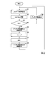
- FIG. 2 is a diagram showing an example of processing performed at sleep time and wake-up time in the wireless terminal device 12 according to the embodiment of the present disclosure.
- the wireless terminal device 12 an attempt is made to transmit an uplink data signal to the base station device 31 at each timing when the control circuit 74 goes from the sleep state to the wake-up state, and the sleep state is repeatedly performed. Show the case. In this processing flow, first, it is assumed that the control circuit 74 is in the activated state.
- Step S1 The transmission circuit 51 wirelessly transmits an uplink data signal to the base station device 31 by the transmission antenna 52, for example, at the initial timing or at the time of waking up. At this time, the transmission circuit 51 and the transmission antenna 52 are controlled by the control circuit 74. Then, the process proceeds to step S2.
- Step S2 The receiving circuit 72 receives the Ack signal or the Nack signal wirelessly transmitted from the base station device 31 to the wireless terminal device 12 by the receiving antenna 71. Then, the process proceeds to step S3.
- Step S3 The Ac / Nack receiving circuit 73 determines whether or not the Ac signal has been received based on the signal received by the receiving circuit 72.
- step S4 when it is determined by the Ac / Nack receiving circuit 73 that the Ac signal has not been received, the control circuit 74 proceeds to the process of step S4. On the other hand, when the control circuit 74 determines that the Ac signal has been received by the Ac / Nack receiving circuit 73, the control circuit 74 proceeds to the process of step S5.
- Step S4 When the Ac signal is not received, the control circuit 74 sets the antenna characteristics to a predetermined content. Then, the process proceeds to step S1. In this case, in the process of step S1, the transmission of the uplink data signal is retransmitted from the second time onward.
- the predetermined content is, for example, an antenna characteristic different from the antenna characteristic set at that time. That is, when the Ac signal is not received, the control circuit 74 changes the antenna characteristic to another content.
- the method for changing the antenna characteristics may be predetermined, for example.
- the technique may include, for example, an order in which a plurality of antenna characteristics are changed.
- the method is based on antenna characteristic setting information.
- the control circuit 74 may switch the plurality of different antenna characteristics in a predetermined order in the process of step S4. Further, for example, when the antenna characteristic setting information defines one antenna characteristic, the control circuit 74 switches to another antenna characteristic in a predetermined manner or randomly in the process of step S4. May be good.
- the same antenna characteristic may be used twice or more continuously. That is, in the process of step S4, the antenna characteristics may not be changed, and the same antenna characteristics as those at the time of the previous transmission may be used at the time of retransmission when the uplink data signal is transmitted a plurality of times.
- the control circuit 74 stores the antenna characteristic setting information based on the antenna characteristic at that time in the memory 75. Then, the process proceeds to step S6.
- the antenna characteristic setting information is, for example, information indicating that the antenna characteristic at least when the Ac signal is received is used.
- the antenna characteristic setting information may be information indicating that one antenna characteristic is used when the Ac signal is received.
- the antenna characteristic setting information is information indicating that one antenna characteristic when an Ac signal is received is set as the first, and the second and subsequent other antenna characteristics are switched in a predetermined order. You may.
- Step S6 The control circuit 74 goes from the activated state to the sleep state. Then, the process proceeds to step S7.
- Step S7 After that, when the predetermined condition is satisfied, the control circuit 74 wakes up and goes from the sleep state to the wake-up state. Then, the process proceeds to step S8.
- the predetermined condition may be an arbitrary condition, and for example, a condition that a predetermined time has elapsed, a condition that a predetermined event has occurred, or the like may be used. The occurrence of the predetermined event may be determined, for example, based on the sensor detection value information detected by the sensor.
- Step S8 The control circuit 74 reads out the antenna characteristic setting information stored in the memory 75, and sets the antenna characteristic of the transmitting antenna 52 according to the antenna characteristic setting information. Then, the process proceeds to step S1. In this case, in the process of step S1, the transmission of the uplink data signal is the transmission of a new uplink data signal.
- the control circuit 74 sets the antenna characteristic in the transmitting antenna 52.
- the antenna characteristic setting information is information that identifies a plurality of different antenna characteristics to be searched in order to search for one antenna characteristic to be set
- the control circuit 74 determines the antenna of the transmitting antenna 52. First, the characteristic is switched to one of the plurality of antenna characteristics to be searched. Here, there are a plurality of antenna characteristics to be searched, and the search order may be determined. In the present embodiment, even if the plurality of antenna characteristics to be searched are the same as a whole, if the search order is different, it is assumed that the information is different for setting the antenna characteristics.
- step S3 when the process of step S3 is repeated, the Ac signal is always received at some stage, but as another example, step S3 When the processing is repeated and the Ac signal is not continuously received a predetermined number of times, a processing flow that temporarily shifts to the processing of step S6 or the like may be used.
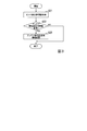
- FIG. 3 is a diagram showing an example of processing performed based on sensor detection value information in the wireless terminal device 12 according to the embodiment of the present disclosure.
- the process shown in FIG. 3 is performed in the wireless terminal device 12 when a predetermined condition is satisfied.
- the predetermined condition may be an arbitrary condition, for example, a condition that a predetermined time has elapsed, or a condition that the control circuit 74 has transitioned from the sleep state to the wake-up state. May be good.
- Step S21 The control circuit 74 acquires sensor detection value information from the sensor of the sensor unit 76. Then, the control circuit 74 shifts to the process of step S22.
- the sensor detection value information may be, for example, sensor detection value information by one sensor, or a combination of sensor detection value information by two or more sensors.
- Step S22 The control circuit 74 determines whether or not to change the antenna characteristic setting information at that time based on the acquired sensor detection value information. As a result, when the control circuit 74 determines that the antenna characteristic setting information is to be changed, the control circuit 74 proceeds to the process of step S23. On the other hand, when the control circuit 74 determines that the antenna characteristic setting information is not changed, the control circuit 74 ends the processing of this processing flow. (Step S23) The control circuit 74 changes the antenna characteristic setting information. Then, the control circuit 74 ends the processing of this processing flow.
- any method may be used as a method for determining whether or not to change the antenna characteristic setting information based on the sensor detection value information. For example, in the wireless communication performed by the wireless terminal device 12. When it is considered that the environment has changed, a method for determining to change the antenna characteristic setting information is used. Further, as a method for changing the antenna characteristic setting information, an arbitrary method may be used. For example, a method for determining the changed antenna characteristic setting information based on the sensor detection value information is used. May be good.
- the wireless terminal device 12 can make a new determination or change of the antenna characteristic setting information based on the sensor detection value information detected by the sensor, but has another configuration.
- a configuration that does not use sensor detection value information may be used.
- the wireless terminal device 12 may not include the sensor unit 76.
- the wireless terminal device 12 will be described in more detail below.
- Various transmission antennas 52 may be used.
- the transmitting antenna 52 an antenna whose antenna characteristics can be changed by changing the feeding point may be used.
- the transmitting antenna 52 an antenna whose antenna characteristics can be changed by changing the short-circuit point may be used.
- an antenna capable of changing the antenna characteristics by switching the non-feeding element (the direction of the beam changes when the impedance is changed) may be used.
- an antenna capable of changing the antenna characteristics by arranging a plurality of antennas side by side (for example, obtaining spatial diversity) may be used.
- an antenna whose antenna characteristics can be changed by changing the order of resonance may be used.
- an antenna capable of changing the antenna characteristics by switching between a state in which a metal piece is connected to the antenna and a state in which the metal piece is not connected to the antenna may be used. ..
- an antenna capable of changing the antenna characteristics by switching the element or the polarization (obtaining the polarization diversity) may be used.
- an antenna whose antenna characteristics can be changed by changing the beamforming by the array antenna may be used.
- an antenna capable of changing the antenna characteristics by changing the decoupling state (the state in which the antenna characteristics are changed when the impedance changes) may be used.
- Various sensors may be used as the sensor of the sensor unit 76 in the wireless terminal device 12.
- the types of sensors include, for example, a geomagnetic sensor that detects geomagnetism, an acceleration sensor that detects acceleration, a pressure sensor that detects pressure pressure, and an optical sensor that detects light.
- the sensor detects changes in the surrounding environment that occur between the time when the uplink data signal is transmitted from the wireless terminal device 12 to the base station device 31 and the time when the next transmission occurs. Changes in the surrounding environment occur, for example, due to the movement of the wireless terminal device 12 or changes in the weather, and in this case, there is a high possibility that the radio wave propagation characteristics will change at the same time. Therefore, in the present embodiment, in the wireless terminal device 12, the control circuit 74 controls the radiation characteristics of the transmitting antenna 52 based on the sensor detection value information. Normally, the process of detecting the value to be detected by the sensor consumes less power than the process of setting one antenna characteristic for the transmitting antenna 52 and trying to transmit the uplink data signal. Therefore, usually, the process of determining the antenna characteristic of the transmitting antenna 52 based on the value detected by the sensor consumes more power than the process of switching the antenna characteristic of the transmitting antenna 52 and trying to transmit the uplink data signal. Is reduced.
- the sensor unit 76 may be provided with a geomagnetic sensor, and the movement of the wireless terminal device 12 may be detected based on the geomagnetism detected by the geomagnetic sensor.
- the geomagnetism is oriented in one direction.
- the magnetic field due to geomagnetism is not uniform. Therefore, the geomagnetism is not uniform inside a reinforced concrete building or the like. Therefore, in the wireless terminal device 12, if there is a change in the magnetic field due to the surrounding geomagnetism, the wireless terminal device 12 may have moved.
- the wireless terminal device 12 when the geomagnetism detected by the geomagnetic sensor in the sensor unit 76 or the control circuit 74 changes by a change amount exceeding a predetermined threshold value, it is determined that the wireless terminal device 12 has moved. be able to. Further, in the wireless terminal device 12, when the geomagnetic map in the building where the wireless terminal device 12 is provided can be used, the sensor unit 76 or the control circuit 74 of the wireless terminal device 12 is based on the geomagnetic map. It is possible to detect the position or the moving distance. In general, the power consumption of the geomagnetic sensor is extremely small, so that it is very suitable for the IoT wireless terminal device 12 and the like.
- the wireless terminal device 12 may include a barometric pressure sensor in the sensor unit 76 and detect a change in weather or movement of the wireless terminal device 12 based on the barometric pressure detected by the barometric pressure sensor.
- the sensor unit 76 or the control circuit 74 can detect a change in weather or movement of the wireless terminal device 12 based on the value detected by the barometric pressure sensor.
- the radio wave propagation characteristics may change. For example, the scattering of radio waves due to rain or the change in reflection characteristics due to the wetness of a building affects the propagation characteristics.
- the change in atmospheric pressure is considered to be the result of a change in altitude of the wireless terminal device 12, it is presumed that when the atmospheric pressure changes, the propagation characteristics of the wireless terminal device 12 change due to the movement of the wireless terminal device 12. You can also.
- the change in the weather and the movement of the wireless terminal device 12 may be determined without distinction, for example, or the change in the weather and the movement of the wireless terminal device 12 can be distinguished by using another sensor or the like. It may be judged.
- the wireless terminal device 12 may include an acceleration sensor in the sensor unit 76 and detect the movement of the wireless terminal device 12 based on the acceleration detected by the acceleration sensor. Specifically, in the wireless terminal device 12, the wireless terminal device 12 is moving when the acceleration detected by the acceleration sensor provided in the wireless terminal device 12 is not 0 in the sensor unit 76 or the control circuit 74. Can be judged. Further, in the wireless terminal device 12, the sensor unit 76 or the control circuit 74 can detect the direction of movement depending on the direction of acceleration. In such a configuration, for example, when an application in which the movement of the wireless terminal device 12 can occur frequently is used, the movement of the wireless terminal device 12 can be reliably detected.
- the sensor unit 76 or the control circuit 74 can estimate the result of integrating the acceleration and the elapsed time as a movement amount, and the calculated movement amount is larger than a predetermined threshold value. If it is small, it can be considered that the wireless terminal device 12 is not moving. In this case, in the wireless terminal device 12, for example, the control circuit 74 may use the previous antenna characteristic setting information stored in the memory 75 as it is. In the wireless terminal device 12, it can be estimated that the sensor unit 76 or the control circuit 74 has a large fluctuation in the propagation characteristics when the movement amount of the wireless terminal device 12 is large.
- the timing of transmitting the uplink data to the base station device 31 and the timing of detecting (sensing) by the sensor of the sensor unit 76 will be described.
- the antenna characteristics of the transmitting antenna 52 are based on one or both of the sensor detection value information and the antenna characteristic setting information stored in the memory 75.
- the set value of the antenna characteristic is set, and the uplink data signal including the data is transmitted to the base station apparatus 31.
- the timing at which the wireless terminal device 12 transmits the uplink data to the base station device 31 may be any timing, for example, a timing at a fixed time interval.
- the control circuit 74 periodically wakes up from the sleep state, determines the antenna characteristics by referring to the sensor detection value information detected by the sensor at that time, and determines the antenna. The characteristics may be set and the uplink data may be transmitted to the base station apparatus 31.
- the sensor may operate after the control circuit 74 of the wireless terminal device 12 wakes up, or even when the control circuit 74 is in the sleep state, the sensor operates continuously or intermittently. The detection may be continued.
- the control circuit 74 changes from the sleep state to the wake-up state when the value detected by the sensor exceeds a predetermined threshold value (an example of the second threshold value) in the sleep state.
- a predetermined threshold value an example of the second threshold value
- a predetermined signal is output from the sensor to a predetermined terminal of the control circuit 74, whereby the control circuit 74 is sent to the terminal.
- the state shifts from the sleep state to the wake-up state.
- sleep is performed when the value detected by the sensor is less than the predetermined threshold value.
- a process for determining the transition from the state to the activated state may be used.
- the timing of transmitting the uplink data to the base station device 31 in the wireless terminal device 12 is, for example, when the sensor is in the surrounding environment when the control circuit 74 is in the sleep state after the transmission process is completed in the wireless terminal device 12. It may be the timing when a situation in which is changed beyond a predetermined degree is detected. In this case, in the wireless terminal device 12, the control circuit 74 wakes up when such a situation is detected, and controls to transmit the uplink data to the base station device 31.
- the wireless terminal device 12 shows a case where a predetermined circuit (sleep target circuit) goes into a sleep state, but as another configuration example, the wireless terminal device 12 has a circuit that goes into a sleep state. Instead, all circuits may be up at all times.
- Radio waves can reach the other party directly, or can reach the other party after being reflected, scattered, or diffracted by a building or the like. Therefore, a signal obtained by synthesizing these can reach the other party. Since a signal has amplitude and phase, it becomes a vector composition, and for example, its magnitudes strengthen and weaken each other. Moreover, since the vectors of these scattered waves differ depending on the frequency, the magnitude of the synthesized wave often has frequency characteristics.
- the i (i represents an integer of 1 or more) th signal xi (t) at time t is given by the equation (1).
- ⁇ c represents the carrier frequency of the signal
- ⁇ i represents the propagation time from the wireless terminal device 12 to the other party of communication
- ⁇ i represents the phase
- Ai represents the amplitude.
- Ai, ⁇ i, and ⁇ i are determined by the surrounding environment and may also differ by frequency.
- Equation (2) Since the signal y (t) reaching the other party of communication is a combination of these signals, it is expressed as in the equation (2). That is, y (t) is the result of synthesizing the vector xi (t).
- N represents an integer of 1 or more, for example, a value of 2 or more
- each signal is numbered from 1 to N. Suppose you are.
- the memory 75 may be, for example, a non-volatile memory (NVM: Non-Volatile Memory) or a volatile memory SRAM (Static Random Access Memory).
- NVM Non-Volatile Memory
- SRAM Static Random Access Memory
- the wireless terminal device 12 can be in a deep sleep state as a sleep state, and power consumption can be significantly reduced. Therefore, for example, the communication frequency is extremely low. Suitable for applications.
- the memory 75 is a volatile memory, the wireless terminal device 12 cannot turn off the power of the memory 75, but the time from waking up to the recovery of the communication line can be shortened. For example, it is suitable for applications that require quick timing.
- the control circuit 74 may switch and use the initial antenna characteristic setting information according to the type of the object to which the wireless terminal device 12 is applied. Specifically, when the first antenna characteristic setting information is suitable for a smart meter and the second antenna characteristic setting information is suitable for a predetermined medical device, these two types of antenna characteristic setting information May be stored in advance in the memory 75 of the wireless terminal device 12.
- the control circuit 74 sets so that the first antenna characteristic setting information suitable for the smart meter is used at the initial stage.
- the control circuit 74 sets so that the second antenna characteristic setting information suitable for a predetermined medical device is initially used.
- the wireless terminal device 12 wirelessly transmits a signal to the base station device 31 by the transmitting antenna 52, and the Ac signal wirelessly transmitted from the base station device 31.
- the control mode of the antenna characteristic of the transmitting antenna 52 (for example, information for setting the antenna characteristic in the present embodiment) is changed based on the reception status of the above. Therefore, the wireless terminal device 12 according to the present embodiment can be controlled so that a control mode of antenna characteristics suitable for the quality of uplink communication to the base station device 31 is used.
- the wireless terminal device 12 retransmits a signal including the same data when the Ac signal is not received. Then, the wireless terminal device 12 changes the control mode of the antenna characteristics of the transmitting antenna 52 based on the number of times the signal is transmitted until the Ac signal is received. Therefore, in the wireless terminal device 12 according to the present embodiment, it is possible to control so that the control mode of the antenna characteristic suitable for the quality of uplink communication estimated based on the reception status of the Ac signal is used.
- the wireless terminal device 12 uses the process of storing the control mode of the antenna characteristics in the memory 75 and the control mode of the antenna characteristics stored in the memory 75. Perform processing. Therefore, in the wireless terminal device 12 according to the present embodiment, for example, a control mode having good antenna characteristics can be stored, and then a control mode having the same antenna characteristics can be used.
- the antenna of the transmitting antenna 52 is based on the value detected by the sensor that detects the value indicating the change in the environment (for example, the surrounding environment).
- the control mode of the characteristic is changed. Therefore, in the wireless terminal device 12 according to the present embodiment, the control mode of the antenna characteristics of the transmitting antenna 52 can be changed according to the change in the environment.
- the wireless terminal device 12 changes the control mode of the antenna characteristics of the transmitting antenna 52 when the value detected by the sensor satisfies a predetermined condition.
- the predetermined condition is a condition that the detected value exceeds a predetermined first threshold value or is a condition that the detected value is less than the predetermined first threshold value. Therefore, in the wireless terminal device 12 according to the present embodiment, the control mode of the antenna characteristics of the transmitting antenna 52 can be changed when the environment changes significantly.
- the wireless terminal device 12 in the wireless terminal device 12, at least a part of the circuits are switched between the sleep state and the activation state. Then, in the wireless terminal device 12, the value is detected by the sensor at the timing when at least a part of the circuits are switched from the sleep state to the wake-up state. Therefore, in the wireless terminal device 12 according to the present embodiment, the change in the environment can be detected at the timing when the predetermined circuit is switched from the sleep state to the wake-up state.
- the wireless terminal device 12 in the wireless terminal device 12, at least a part of the circuits are switched between the sleep state and the activation state. Then, in the wireless terminal device 12, when at least a part of the circuits are in the sleep state and the value detected by the sensor satisfies a predetermined condition, the at least a part of the circuits is in the wake-up state from the sleep state. Switch to.
- the predetermined condition is a condition that the detected value exceeds a predetermined second threshold value or a condition that the detected value is less than a predetermined second threshold value. Therefore, in the wireless terminal device 12 according to the present embodiment, when the predetermined circuit is in the sleep state and the environment is significantly changed, the predetermined circuit can be switched from the sleep state to the wake-up state.
- the control mode of the antenna characteristic of the transmitting antenna 52 represents one antenna characteristic to be set. Therefore, in the wireless terminal device 12 according to the present embodiment, it is possible to control so that one antenna characteristic suitable for the quality of uplink communication to the base station device 31 is used.
- the control mode of the antenna characteristics of the transmitting antenna 52 represents a plurality of different antenna characteristics to be searched. Therefore, the wireless terminal device 12 according to the present embodiment can be controlled so that processing based on a plurality of different antenna characteristics to be searched is performed according to the quality of uplink communication to the base station device 31.
- the wireless terminal device 12 switches to use all of the plurality of antenna characteristics represented by the control mode of the antenna characteristics of the transmitting antenna 52. Therefore, in the wireless terminal device 12 according to the present embodiment, the optimum antenna characteristics can be specified by using all of the plurality of different antenna characteristics to be searched.
- the wireless terminal device 12 switches to use a part of the plurality of antenna characteristics represented by the control mode of the antenna characteristics of the transmitting antenna 52. Therefore, in the wireless terminal device 12 according to the present embodiment, by using a part of a plurality of different antenna characteristics to be searched, it is unclear whether the optimum antenna characteristics are used, but good antenna characteristics are quickly identified. be able to.
- the wireless terminal device 12 switches the antenna characteristics of the transmitting antenna 52 when the Ac signal is not received. Therefore, in the wireless terminal device 12 according to the present embodiment, when the Ac signal is not received, it is considered that the antenna characteristic set in the transmitting antenna 52 is not good, and the antenna characteristic can be switched to another antenna characteristic. it can.
- the control mode of the antenna characteristics of the transmitting antenna 52 includes a search order for two or more different antenna characteristics. Therefore, in the wireless terminal device 12 according to the present embodiment, the search for confirming whether or not each of the plurality of antenna characteristics is good can be performed in the order of the search suitable for the plurality of antenna characteristics.
- the base station device 31 receives a signal wirelessly transmitted from the wireless terminal device 12, and when the signal is normally received, an Ac signal for the signal is transmitted. Wireless transmission is performed to the wireless terminal device 12. Therefore, in the information communication system 1 according to the present embodiment, the wireless terminal device 12 can be controlled so that a control mode of antenna characteristics suitable for the quality of uplink communication to the base station device 31 is used.
- the wireless terminal device 12 is applied to the IoT (CIOT) using the cellular system.
- CIOT wireless terminal devices are generally installed together with sensors or actuators without human intervention in communication, and are automatically installed. Perform data communication.
- a CIOT wireless terminal device is applicable to various applications such as smart meters, medical devices, virtual reality (VR: Virtual Reality) or augmented reality (AR) devices, and automobiles. It has been expanded and is flourishing.
- a smart meter is a device that automatically measures the amount of electricity, gas, water, etc. used in each house and transmits the measured values wirelessly. These usage data are data that do not need to be transmitted frequently.
- smart meter devices are generally battery-powered. Therefore, as a CIOT communication method used for such an application, a low power consumption communication method such as Category M1 or NB-IoT has been introduced.
- a CIOT wireless communication device for example, there is only one RF circuit instead of the MIMO (Multiple Input Multiple Output) method in which a plurality of antennas and RF (Radio Frequency) circuits, which are common in smartphones, are mounted. It is generally installed. Therefore, an omnidirectional antenna is generally used as the antenna.
- MIMO Multiple Input Multiple Output
- RF Radio Frequency
- an eDRX (extended Discontinuus Reception) method in which the sleep time when not communicating is extended is adopted.
- Meter devices such as electric power, gas, and water are generally installed in relatively inconspicuous places such as shadows of buildings or gaps between buildings. Moreover, such meter equipment will not be moved after the installation work has been done. For this reason, in such a meter device, the radio wave propagation characteristics are not always good at the installation location, and changes in the environment cannot be expected. In such a meter device, when the radio wave propagation environment is not good, the line quality of data transmission is low. Therefore, repeated retransmissions and the like increase power consumption and shorten battery life, resulting in shortening of battery life. In addition, operating costs will increase.
- the direction of the antenna beam after waking up of the wireless terminal device is often not determined.
- the process of re-adjusting the direction of the antenna beam after waking up was performed, which did not lead to the reduction of power consumption.
- a diversity method can be considered as a method for improving transmission characteristics.
- the reception diversity effect can be obtained by switching the antenna characteristics while observing the quality of the received signal. For example, regarding transmission, when the TDD (Time Division Duplex) method is used, the same frequency is used for uplink and downlink, so that an antenna with high downlink transmission quality also has high uplink transmission quality. is expected.
- TDD Time Division Duplex
- the transmission quality of the propagation path may deteriorate. Due to the use case, the IoT wireless terminal device may not move after being installed once, and in this case, even if the radio wave propagation environment is bad, there is no opportunity for the propagation environment to improve.
- the IoT wireless terminal device is equipped with an omnidirectional antenna, and it has not been possible to improve the line quality in the multiple propagation path.
- power consumption is reduced in order to extend the battery life, and only one antenna and one receiving circuit are mounted in both the standard and the practical state. Therefore, in the IoT wireless terminal device, it is not possible to introduce a technique for trying to improve the line quality by using a plurality of antennas and receiving circuits such as MIMO.
- Beamforming antennas are expected to help improve the line quality of IoT wireless terminal devices.
- the optimum setting value for reception does not always apply at the time of transmission.
- the optimum set value is generally different because the frequencies of the transmission signal and the reception signal are different.
- the FDD method is widely adopted, and the characteristics of the upstream propagation path and the characteristics of the downstream propagation path are different.
- the base station device does not notify the wireless terminal device of a signal that directly evaluates the quality of the uplink signal.
- IoT radio transmission opportunities are often extremely small. Further, in IoT radio, it is often necessary to take a long sleep time in order to extend the life of the battery. Therefore, in the IoT radio, it is not desirable to take a long wake-up time for control in a situation where the opportunity to control the beamforming antenna is very small, which leads to shortening the battery life.
- the IoT wireless terminal device does not have a function of directly obtaining the transmission quality of the uplink signal.
- the IoT wireless terminal device can have a function of indirectly obtaining the transmission quality of the uplink signal based on the Ac signal / Nack signal notified from the base station device to the wireless terminal device. That is, in the IoT wireless terminal device, it is possible to use the function of repeating the transmission of the same data until the Ac signal is received.
- an omnidirectional antenna is used in the wireless terminal device, there is no way to improve the propagation characteristics of the omnidirectional antenna, and the transmission success is stochastically increased by retransmitting the same data. It was just.
- the information communication system 1 including the base station device 31 and the wireless terminal device 12 in the cellular system is illustrated, but the terminal device similar to the wireless terminal device 12 according to the present embodiment can be used in various systems. May be applied.
- the communication partner device of the terminal device may be an access point device.
- the communication partner device of the terminal device may be another terminal device.
- the terminal device and its communication partner device may have a master-slave relationship or an equal relationship in communication.
- a transmitter that wirelessly transmits a signal containing data to a communication partner device using a transmitting antenna
- a receiving unit that receives the Ac signal wirelessly transmitted from the communication partner device by the receiving antenna
- a control unit that changes the control mode of the antenna characteristics of the transmitting antenna based on the reception status of the Ac signal received by the receiving unit.
- control unit wirelessly transmits the signal to the communication partner device by the transmission unit by the transmission antenna and the Ac signal is not received by the reception unit, the data is transmitted by the transmission unit. Retransmit the signal containing The control unit changes the control mode of the antenna characteristics of the transmitting antenna based on the number of transmissions of the signal including the data performed by the receiving unit until the Ac signal is received.
- the information communication device according to [1].
- a memory for storing the control mode of the antenna characteristics is provided.
- the control unit performs a process of storing the control mode of the antenna characteristic in the memory and a process of reading and using the control mode of the antenna characteristic stored in the memory.
- the information communication device according to [1] or [2].
- the control unit changes the control mode of the antenna characteristics of the transmitting antenna based on the value detected by the sensor.
- the information communication device according to any one of [1] to [3].
- the control unit changes the control mode of the antenna characteristics of the transmitting antenna when the value detected by the sensor satisfies a predetermined condition.
- the sensor detects the value at the timing when at least a part of the circuits switch from the sleep state to the wake-up state.
- At least some circuits switch between sleep and wake When the at least a part of the circuits are in the sleep state and the value detected by the sensor satisfies a predetermined condition, the at least a part of the circuits switch from the sleep state to the wake-up state.
- the information communication device according to [4] or [5].
- the control mode of the antenna characteristic of the transmitting antenna represents one antenna characteristic to be set.
- the information communication device according to any one of [1] to [7].
- the control mode of the antenna characteristics of the transmitting antenna represents a plurality of different antenna characteristics.
- the information communication device according to any one of [1] to [7].
- the control unit switches to use all of the plurality of antenna characteristics represented by the control mode of the antenna characteristics of the transmitting antenna.
- the information communication device according to [9].
- the control unit switches to use a part of the plurality of antenna characteristics represented by the control mode of the antenna characteristics of the transmitting antenna.
- the information communication device according to [9].
- the control unit switches the antenna characteristics of the transmitting antenna when the Ac signal is not received by the receiving unit.
- the information communication device according to any one of [9] to [11].
- the control mode of the antenna characteristics of the transmitting antenna includes a switching order for two or more different antenna characteristics.
- the information communication device according to any one of [9] to [12].
- the transmitting antenna and the receiving antenna are shared antennas.
- the information communication device according to any one of [1] to [13].
- the first information communication device is A transmission unit that wirelessly transmits a signal containing data to the second information communication device by a transmission antenna, A receiving unit that receives the Ac signal wirelessly transmitted from the second information communication device by the receiving antenna, and A control unit that changes the control mode of the antenna characteristics of the transmitting antenna based on the reception status of the Ac signal received by the receiving unit.
- the second information communication device is The communication unit includes a communication unit that receives the signal wirelessly transmitted from the first information communication device and wirelessly transmits the Ac signal to the received signal to the first information communication device.
- Information communication system is A transmission unit that wirelessly transmits a signal containing data to the second information communication device by a transmission antenna, A receiving unit that receives the Ac signal wirelessly transmitted from the second information communication device by the receiving antenna, and A control unit that changes the control mode of the antenna characteristics of the transmitting antenna based on the reception status of the Ac signal received by the receiving unit.
- a program for realizing the function of an arbitrary component in any device described above may be recorded on a computer-readable recording medium, and the program may be read into a computer system and executed.
- computer system includes hardware such as an operating system (OS: Operating System) or peripheral devices.
- OS Operating System
- computer-readable recording medium refers to a portable medium such as a flexible disk, a magneto-optical disk, a ROM, a CD (Compact Disk) -ROM, or a storage device such as a hard disk built in a computer system. ..
- a "computer-readable recording medium” is a volatile memory (RAM) inside a computer system that serves as a server or client when a program is transmitted via a network such as the Internet or a communication line such as a telephone line.
- RAM volatile memory
- the above program may be transmitted from a computer system in which this program is stored in a storage device or the like to another computer system via a transmission medium or by a transmission wave in the transmission medium.
- the "transmission medium" for transmitting a program refers to a medium having a function of transmitting information, such as a network such as the Internet or a communication line such as a telephone line.
- the above program may be for realizing a part of the above-mentioned functions.
- the above program may be a so-called difference file that can realize the above-mentioned functions in combination with a program already recorded in the computer system.
- the difference file may be called a difference program.
- each process in the present embodiment may be realized by a processor that operates based on information such as a program and a computer-readable recording medium that stores information such as a program.
- the functions of each part may be realized by individual hardware, or the functions of each part may be realized by integrated hardware.
- the processor includes hardware, which may include at least one of a circuit that processes a digital signal and a circuit that processes an analog signal.
- the processor may be configured using one or more circuit devices mounted on a circuit board, or one or both of one or more circuit elements.
- An IC (Integrated Circuit) or the like may be used as the circuit device, and a resistor or a capacitor may be used as the circuit element.
- the processor may be, for example, a CPU.
- the processor is not limited to the CPU, and various processors such as GPU (Graphics Processing Unit) or DSP (Digital Signal Processor) may be used.
- the processor may be, for example, a hardware circuit by an ASIC (Application Specific Integrated Circuit).
- the processor may be composed of, for example, a plurality of CPUs, or may be composed of a hardware circuit by a plurality of ASICs.
- the processor may be composed of, for example, a combination of a plurality of CPUs and a hardware circuit by a plurality of ASICs.
- the processor may include, for example, one or more of an amplifier circuit or a filter circuit for processing an analog signal.
- 1 Information communication system, 11 ... Base station side device, 12 ... Wireless terminal device, 31 ... Base station device, 32 ... Ac / Nack discrimination circuit, 51 ... Transmission circuit, 52 ... Transmission antenna, 71 ... Reception antenna, 72 ... Reception circuit, 73 ... Ack / Nack reception circuit, 74 ... Control circuit, 75 ... Memory, 76 ... Sensor unit, 111-113 ... Uplink data signal, 131 ... Ack / Nack signal, 151-152 ... Antenna characteristics
Landscapes
- Engineering & Computer Science (AREA)
- Signal Processing (AREA)
- Computer Networks & Wireless Communication (AREA)
- Mobile Radio Communication Systems (AREA)
Abstract
情報通信装置は、通信相手装置に対して送信アンテナによってデータを含む信号を無線送信する送信部と、前記通信相手装置から無線送信されるAck信号を、受信アンテナによって、受信する受信部と、前記受信部によって受信される前記Ack信号の受信状況に基づいて、前記送信アンテナのアンテナ特性の制御態様を変更する制御部と、を備える。
Description
本開示は、情報通信装置および情報通信システムに関する。
IoT(Internet on Things)における無線端末装置では、単一の無線回路が搭載されるため、無指向性アンテナが採用されていた。
セルラのシステムに向けられたIoTを例とすると、無線端末装置と基地局装置とが無線通信を行う。一般に、無線端末装置から基地局装置への方向を上りと呼び、基地局装置から無線通信装置への方向を下りと呼ぶ。
セルラのシステムに向けられたIoTを例とすると、無線端末装置と基地局装置とが無線通信を行う。一般に、無線端末装置から基地局装置への方向を上りと呼び、基地局装置から無線通信装置への方向を下りと呼ぶ。
無線端末装置は、基地局装置に対して、上りデータ信号を無線送信する。基地局装置は、当該上りデータ信号を受信し、当該上りデータ信号が正しく受信されたかどうかを判別回路によって判別し、当該判別結果に応じてAckまたはNackの信号を無線端末装置に無線送信する。ここで、Ack信号は正常に受信されたことを表し、Nack信号は正常に受信されなかったことを表す。
無線端末装置は、基地局装置からAck信号を受信した場合には、次の上りデータ信号を基地局装置に無線送信する。一方、無線端末装置は、基地局装置からNack信号を受信した場合、あるいは、基地局装置からAck信号もNack信号も受信することができなかった場合には、同一のデータを含む上りデータ信号を基地局装置に再送する。
無線端末装置は、基地局装置からAck信号を受信した場合には、次の上りデータ信号を基地局装置に無線送信する。一方、無線端末装置は、基地局装置からNack信号を受信した場合、あるいは、基地局装置からAck信号もNack信号も受信することができなかった場合には、同一のデータを含む上りデータ信号を基地局装置に再送する。
特許文献1に記載された通信装置では、あるアンテナビームでデータが正しく送られていないことが判断された場合、アンテナビームを変更して異なる伝播パスを選択してデータを再送することが行われている(特許文献1参照。)。特許文献1に記載された技術は、特に、ビデオデータなどのストリーミング的なデータの伝送に向けたものである。ビデオデータのような連続的なデータの伝送の場合には、伝送中に指向性を制御することで、より通信品質を改善することができる。
しかしながら、特許文献1に記載される技術のようなIoTの無線端末装置では、アンテナビームの調整の回数が多くなり、消費電力が大きくなる場合があった。また、このようなことは、IoT以外の情報通信装置においても生じる場合があった。
本開示は、このような事情を考慮してなされたもので、消費電力を抑えつつ、通信相手装置へのデータ送信の品質を確保することができる情報通信装置および情報通信システムを提供することを課題とする。
本開示の一側面は、通信相手装置に対して送信アンテナによってデータを含む信号を無線送信する送信部と、前記通信相手装置から無線送信されるAck信号を、受信アンテナによって、受信する受信部と、前記受信部によって受信される前記Ack信号の受信状況に基づいて、前記送信アンテナのアンテナ特性の制御態様を変更する制御部と、を備える情報通信装置である。
本開示の一側面は、情報通信装置において、前記制御部は、前記送信部によって前記通信相手装置に対して前記送信アンテナによって前記信号を無線送信したときに、前記受信部によって前記Ack信号が受信されなかった場合に、前記送信部によって前記データを含む信号を再送し、前記制御部は、前記受信部によって前記Ack信号が受信されるまでに行われた前記データを含む信号の送信の回数に基づいて、前記送信アンテナのアンテナ特性の制御態様を変更する。
本開示の一側面は、情報通信装置において、さらに、前記アンテナ特性の制御態様を記憶するメモリを備え、前記制御部は、前記アンテナ特性の制御態様を前記メモリに記憶させる処理、および、前記メモリに記憶された前記アンテナ特性の制御態様を読み出して使用する処理を行う。
本開示の一側面は、情報通信装置において、さらに、環境の変化を表す値を検出するセンサを備え、前記制御部は、前記センサによって検出された前記値に基づいて、前記送信アンテナのアンテナ特性の制御態様を変更する。
本開示の一側面は、情報通信装置において、前記制御部は、前記センサによって検出された前記値が所定の条件を満たす場合に、前記送信アンテナのアンテナ特性の制御態様を変更する。
本開示の一側面は、情報通信装置において、少なくとも一部の回路がスリープ状態と起動状態とで切り替わり、前記少なくとも一部の回路が前記スリープ状態から前記起動状態へ切り替わったタイミングで、前記センサによって前記値を検出する。
本開示の一側面は、情報通信装置において、少なくとも一部の回路がスリープ状態と起動状態とで切り替わり、前記少なくとも一部の回路が前記スリープ状態にあるときに、前記センサによって検出された前記値が所定の条件を満たす場合に、前記少なくとも一部の回路が前記スリープ状態から前記起動状態へ切り替わる。
本開示の一側面は、情報通信装置において、前記送信アンテナのアンテナ特性の制御態様は、設定されるべき1つのアンテナ特性を表す。
本開示の一側面は、情報通信装置において、前記送信アンテナのアンテナ特性の制御態様は、複数の異なるアンテナ特性を表す。
本開示の一側面は、情報通信装置において、前記制御部は、前記送信アンテナのアンテナ特性の制御態様によって表される前記複数の前記アンテナ特性のすべてを使用するように切り替える。
本開示の一側面は、情報通信装置において、前記制御部は、前記送信アンテナのアンテナ特性の制御態様によって表される前記複数の前記アンテナ特性のうちの一部を使用するように切り替える。
本開示の一側面は、情報通信装置において、前記制御部は、前記受信部によって前記Ack信号が受信されなかった場合に、前記送信アンテナのアンテナ特性を切り替える。
本開示の一側面は、情報通信装置において、前記送信アンテナのアンテナ特性の制御態様は、2以上の異なるアンテナ特性について、切り替えの順序を含む。
本開示の一側面は、情報通信装置において、前記送信アンテナと前記受信アンテナは共用されたアンテナである。
本開示の一側面は、第1の情報通信装置と第2の情報通信装置を備え、前記第1の情報通信装置は、前記第2の情報通信装置に対して送信アンテナによってデータを含む信号を無線送信する送信部と、前記第2の情報通信装置から無線送信されるAck信号を、受信アンテナによって、受信する受信部と、前記受信部によって受信される前記Ack信号の受信状況に基づいて、前記送信アンテナのアンテナ特性の制御態様を変更する制御部と、を備え、前記第2の情報通信装置は、前記第1の情報通信装置から無線送信される前記信号を受信し、受信された前記信号に対する前記Ack信号を前記第1の情報通信装置に対して無線送信する通信部を備える、情報通信システムである。
以下、図面を参照し、実施形態について説明する。
[情報通信システムの構成の概要]
図1は、本開示の実施形態に係る情報通信システム1の概略的な構成を示す図である。
情報通信システム1は、基地局側装置11と、無線端末装置12を備える。
本実施形態では、無線端末装置12は、情報通信装置の一例であり、また、第1の情報通信装置の一例である。
図1は、本開示の実施形態に係る情報通信システム1の概略的な構成を示す図である。
情報通信システム1は、基地局側装置11と、無線端末装置12を備える。
本実施形態では、無線端末装置12は、情報通信装置の一例であり、また、第1の情報通信装置の一例である。
本実施形態では、基地局側装置11および無線端末装置12は、IoTの装置である。
IoTとしては、例えば、セルラ(Cellular)のシステムに向けられたIoT(CIoT)が用いられてもよい。セルラシステムは、一例として、Third Generation Partnership PROGRAM(3GPP)で標準化されているシステムであり、携帯電話として世界で広く使用されているシステムである。特に、本実施形態では、LTE Release13で標準化されたCategory M1あるいはNB-IoTといった方式を採用したセルラシステムのIoTを想定して説明する。
IoTとしては、例えば、セルラ(Cellular)のシステムに向けられたIoT(CIoT)が用いられてもよい。セルラシステムは、一例として、Third Generation Partnership PROGRAM(3GPP)で標準化されているシステムであり、携帯電話として世界で広く使用されているシステムである。特に、本実施形態では、LTE Release13で標準化されたCategory M1あるいはNB-IoTといった方式を採用したセルラシステムのIoTを想定して説明する。
基地局側装置11は、基地局装置31と、Ack/Nack判別回路32を備える。なお、本実施形態では、基地局装置31とAck/Nack判別回路32とを別体で示したが、これらが一体として構成されてもよい。この場合、本実施形態における基地局側装置11は、基地局装置と呼ばれてもよい。
本実施形態では、基地局側装置11は、無線端末装置12から見た通信相手装置の一例であり、また、第2の情報通信装置の一例である。また、本実施形態では、基地局装置31は、通信部の一例である。
本実施形態では、基地局側装置11は、無線端末装置12から見た通信相手装置の一例であり、また、第2の情報通信装置の一例である。また、本実施形態では、基地局装置31は、通信部の一例である。
無線端末装置12は、送信回路51と、送信アンテナ52と、受信アンテナ71と、受信回路72と、Ack/Nack受信回路73と、制御回路74と、メモリ75と、センサ部76を備える。
本実施形態では、送信回路51は送信部の一例であり、受信回路72は受信部の一例であり、制御回路74は制御部の一例である。
本実施形態では、送信回路51は送信部の一例であり、受信回路72は受信部の一例であり、制御回路74は制御部の一例である。
送信アンテナ52としては、送信時のアンテナ特性を変更することが可能なアンテナが用いられている。ここで、アンテナ特性は、例えば、アンテナの指向性、あるいは、アンテナの放射特性などと呼ばれてもよい。
なお、図1には、2つのアンテナ特性151~152を模式的に示してあるが、送信アンテナ52によって実現されるアンテナ特性の数は任意であってもよく、3以上であってもよい。
なお、図1には、2つのアンテナ特性151~152を模式的に示してあるが、送信アンテナ52によって実現されるアンテナ特性の数は任意であってもよく、3以上であってもよい。
また、送信アンテナ52と受信アンテナ71とは、例えば、それぞれ独立したアンテナであってもよく、あるいは、送信と受信とで共用された共通のアンテナであってもよい。送信と受信とで共用された共通のアンテナが用いられる場合、当該アンテナは、送信と受信とで異なるアンテナ特性になるように制御されてもよい。
センサ部76は、周辺環境の変化を表す値を検出するセンサを1以上備える。
制御回路74は、無線端末装置12における各部の制御を行う。
また、無線端末装置12は、例えば、バッテリ(図示を省略する。)を備え、当該バッテリの電力を用いて動作を行う。この場合、バッテリを持続させるために、特に、消費電力の低減が重要になる。
センサ部76は、周辺環境の変化を表す値を検出するセンサを1以上備える。
制御回路74は、無線端末装置12における各部の制御を行う。
また、無線端末装置12は、例えば、バッテリ(図示を省略する。)を備え、当該バッテリの電力を用いて動作を行う。この場合、バッテリを持続させるために、特に、消費電力の低減が重要になる。
[情報通信システムにおける処理の概要]
無線端末装置12および基地局側装置11において行われる処理を説明する。
無線端末装置12では、送信回路51は、上りのデータを含む信号である上りデータ信号を、送信アンテナ52によって、基地局装置31に対して無線送信する。これにより、当該上りデータ信号が、上り周波数で、無線端末装置12から基地局装置31に伝送される。なお、図1には、上りデータ信号111~113を模式的に例示してある。
この場合に、無線端末装置12では、制御回路74は、上り通信の伝播特性が良好となるように、送信アンテナ52のアンテナ特性を適応的に制御する。例えば、制御回路74は、送信アンテナ52の制御態様を変更することで、変更後の制御態様に基づくアンテナ特性となるように制御する。
無線端末装置12および基地局側装置11において行われる処理を説明する。
無線端末装置12では、送信回路51は、上りのデータを含む信号である上りデータ信号を、送信アンテナ52によって、基地局装置31に対して無線送信する。これにより、当該上りデータ信号が、上り周波数で、無線端末装置12から基地局装置31に伝送される。なお、図1には、上りデータ信号111~113を模式的に例示してある。
この場合に、無線端末装置12では、制御回路74は、上り通信の伝播特性が良好となるように、送信アンテナ52のアンテナ特性を適応的に制御する。例えば、制御回路74は、送信アンテナ52の制御態様を変更することで、変更後の制御態様に基づくアンテナ特性となるように制御する。
ここで、無線端末装置12から基地局側装置11に送信される上りデータとしては、任意のデータが用いられてもよく、例えば、基地局側装置11の側において収集されて管理されるデータが用いられてもよい。具体的には、無線端末装置12がスマートメータに適用される場合には、上りデータとして当該スマートメータによって測定された値を表すデータが用いられてもよく、あるいは、無線端末装置12が医療機器に適用される場合には、上りデータとして当該医療機器によって測定された値を表すデータが用いられてよく、他も同様である。
基地局装置31では、無線端末装置12から伝送されてくる上りデータ信号を受信する。そして、基地局装置31では、無線端末装置12から受信された上りデータ信号をAck/Nack判別回路32に出力する。
Ack/Nack判別回路32では、基地局装置31から入力された上りデータ信号が正常に受信されたか否かを判別する。この結果、Ack/Nack判別回路32では、上りデータ信号が正常に受信されたと判別された場合には、Ack信号を基地局装置31に出力する。一方、Ack/Nack判別回路32では、上りデータ信号が正常に受信されなかったと判別された場合には、Nack信号を基地局装置31に出力する。
基地局装置31では、Ack/Nack判別回路32からAck信号が入力された場合には、無線端末装置12に対して、当該Ack信号を無線送信する。一方、基地局装置31では、Ack/Nack判別回路32からNack信号が入力された場合には、無線端末装置12に対して、当該Nack信号を無線送信する。
これらにより、AcK信号またはNack信号(説明の便宜上、両方の信号をまとめてAck/Nack信号とも呼ぶ。)が、下り信号として、下り周波数で、基地局装置31から無線端末装置12に伝送される。なお、図1には、下り信号であるAck/Nack信号131を模式的に例示してある。
これらにより、AcK信号またはNack信号(説明の便宜上、両方の信号をまとめてAck/Nack信号とも呼ぶ。)が、下り信号として、下り周波数で、基地局装置31から無線端末装置12に伝送される。なお、図1には、下り信号であるAck/Nack信号131を模式的に例示してある。
無線端末装置12では、基地局装置31から伝送されてくるAck信号またはNack信号を受信アンテナ71によって受信する。
ここで、本実施形態では、基地局装置31は、常時、所定の報知信号を無線により発信している。そして、無線端末装置12では、受信回路72は、受信アンテナ71によって当該報知信号を受信して、当該報知信号の受信強度を検出している。無線端末装置12では、制御回路74は、当該受信強度に基づいて、必要に応じて、受信アンテナ71のアンテナ特性を適応的に制御してもよい。なお、無線端末装置12では、受信アンテナ71のアンテナ特性については、任意に制御されてもよく、本実施形態では、詳細な説明を省略する。
ここで、本実施形態では、基地局装置31は、常時、所定の報知信号を無線により発信している。そして、無線端末装置12では、受信回路72は、受信アンテナ71によって当該報知信号を受信して、当該報知信号の受信強度を検出している。無線端末装置12では、制御回路74は、当該受信強度に基づいて、必要に応じて、受信アンテナ71のアンテナ特性を適応的に制御してもよい。なお、無線端末装置12では、受信アンテナ71のアンテナ特性については、任意に制御されてもよく、本実施形態では、詳細な説明を省略する。
無線端末装置12では、受信回路72は、受信アンテナ71によって受信されたAck信号またはNack信号について所定の処理を実行し、当該処理が実行された後の信号をAck/Nack受信回路73に出力する。当該所定の処理としては、任意の処理が用いられてもよく、例えば、信号を増幅する処理などのように、一般的な信号受信時の処理が用いられてもよい。
無線端末装置12では、Ack/Nack受信回路73は、受信回路72から入力された信号がAck信号であるかNack信号であるかを判断する。そして、Ack/Nack受信回路73は、この判断の結果を表す情報を制御回路74に出力する。
無線端末装置12では、Ack/Nack受信回路73は、受信回路72から入力された信号がAck信号であるかNack信号であるかを判断する。そして、Ack/Nack受信回路73は、この判断の結果を表す情報を制御回路74に出力する。
無線端末装置12では、制御回路74は、Ack/Nack受信回路73から入力される情報に基づいて、送信済みの上りデータ信号に対してAck信号が基地局装置31から受信されたか、または、送信済みの上りデータ信号に対してNack信号が基地局装置31から受信されたかを判断する。
そして、無線端末装置12では、制御回路74は、ある上りデータ信号に対してAck信号が基地局装置31から受信されたと判断された場合には、当該上りデータ信号が基地局装置31によって正常に受信されたことを判断して管理する。一方、制御回路74は、ある上りデータ信号に対してNack信号が基地局装置31から伝送されたと判断された場合には、当該上りデータ信号を基地局装置31に対して再送するように、送信回路51を制御する。
無線端末装置12では、制御回路74は、例えば、基地局装置31からAck信号が受信される状況に基づいて、送信アンテナ52のアンテナ特性を設定する。一例として、制御回路74は、基地局装置31に対してデータの送信および再送を行う場合に、何回目のデータ送信に対して基地局装置31からAck信号が受信されるかによって、アンテナ特性を決定してもよい。
そして、無線端末装置12では、制御回路74は、ある上りデータ信号に対してAck信号が基地局装置31から受信されたと判断された場合には、当該上りデータ信号が基地局装置31によって正常に受信されたことを判断して管理する。一方、制御回路74は、ある上りデータ信号に対してNack信号が基地局装置31から伝送されたと判断された場合には、当該上りデータ信号を基地局装置31に対して再送するように、送信回路51を制御する。
無線端末装置12では、制御回路74は、例えば、基地局装置31からAck信号が受信される状況に基づいて、送信アンテナ52のアンテナ特性を設定する。一例として、制御回路74は、基地局装置31に対してデータの送信および再送を行う場合に、何回目のデータ送信に対して基地局装置31からAck信号が受信されるかによって、アンテナ特性を決定してもよい。
なお、本実施形態では、無線端末装置12から無線送信された上りデータ信号が基地局装置31に到達しなかった場合には、無線端末装置12では、基地局装置31からAck信号もNack信号も受信しない。この場合、無線端末装置12では、制御回路74は、ある上りデータ信号が基地局装置31に対して無線送信された後に、所定の時間が経過しても基地局装置31からAck信号またはNack信号が受信されない場合には、タイムアウトとして、当該上りデータ信号を基地局装置31に対して再送するように、送信回路51を制御してもよい。
本実施形態では、無線端末装置12では、所定の回路は、起動状態とスリープ状態を有する。本実施形態では、説明の便宜上、当該所定の回路をスリープ対象回路と呼んで説明する。
ここで、スリープ対象回路の起動状態は、スリープ対象回路が起動している状態であり、スリープ対象回路において起動状態における所定の機能の処理を実行することが可能な状態である。また、スリープ対象回路のスリープ状態は、スリープ対象回路が起動状態と比べて低消費電力の状態であり、スリープ対象回路においてスリープ状態における所定の機能の処理を実行することが可能である。
起動状態における所定の機能の処理と、スリープ状態における所定の機能の処理とは、一部または全部が、相違している。例えば、スリープ状態における所定の機能の処理は、起動状態における所定の機能の処理と比べて、消費電力が低い処理である。
スリープ対象回路は、例えば、起動状態における所定の機能の処理を実行することが必要なときには起動状態へ移行する一方、それ以外のときにはスリープ状態へ移行し、これらにより、間欠動作を行ってもよい。
ここで、スリープ対象回路の起動状態は、スリープ対象回路が起動している状態であり、スリープ対象回路において起動状態における所定の機能の処理を実行することが可能な状態である。また、スリープ対象回路のスリープ状態は、スリープ対象回路が起動状態と比べて低消費電力の状態であり、スリープ対象回路においてスリープ状態における所定の機能の処理を実行することが可能である。
起動状態における所定の機能の処理と、スリープ状態における所定の機能の処理とは、一部または全部が、相違している。例えば、スリープ状態における所定の機能の処理は、起動状態における所定の機能の処理と比べて、消費電力が低い処理である。
スリープ対象回路は、例えば、起動状態における所定の機能の処理を実行することが必要なときには起動状態へ移行する一方、それ以外のときにはスリープ状態へ移行し、これらにより、間欠動作を行ってもよい。
ここで、本実施形態では、無線端末装置12におけるスリープ状態として、制御回路74等のスリープ状態および起動状態が切り替えられる場合を示すが、スリープ状態と起動状態とが切り替えられる回路としては、任意の回路であってもよい。
スリープ対象回路としては、例えば、制御回路74のみであってもよく、あるいは、制御回路74と他の所定の回路であってもよく、また、他の構成例として、制御回路74はスリープ状態とならずに、他の所定の回路のみがスリープ状態となってもよい。当該他の所定の回路としては、無線回路などが用いられてもよい。
本実施形態では、スリープ対象回路は、少なくとも制御回路74を含み、さらに、無線通信に関する他の回路の部分を含んでもよい。
スリープ対象回路としては、例えば、制御回路74のみであってもよく、あるいは、制御回路74と他の所定の回路であってもよく、また、他の構成例として、制御回路74はスリープ状態とならずに、他の所定の回路のみがスリープ状態となってもよい。当該他の所定の回路としては、無線回路などが用いられてもよい。
本実施形態では、スリープ対象回路は、少なくとも制御回路74を含み、さらに、無線通信に関する他の回路の部分を含んでもよい。
無線端末装置12では、制御回路74は、メモリ75に各種の情報を書き込んで記憶させること、あるいは、メモリ75に記憶された各種の情報を読み出すことを行う。
本実施形態では、制御回路74は、アンテナ特性を設定するための情報(説明の便宜上、アンテナ特性設定用情報と呼ぶ。)をメモリ75に書き込んで記憶させる処理、および、メモリ75に記憶されたアンテナ特性設定用情報を読み出す処理を行う。
本実施形態では、アンテナ特性設定用情報は、アンテナ特性の制御態様の一例である。
ここで、アンテナ特性設定用情報は、例えば、設定すべき1つのアンテナ特性を特定する情報であってもよく、あるいは、設定すべき1つのアンテナ特性を探索するために探索すべき複数の異なるアンテナ特性を特定する情報であってもよい。
本実施形態では、制御回路74は、アンテナ特性を設定するための情報(説明の便宜上、アンテナ特性設定用情報と呼ぶ。)をメモリ75に書き込んで記憶させる処理、および、メモリ75に記憶されたアンテナ特性設定用情報を読み出す処理を行う。
本実施形態では、アンテナ特性設定用情報は、アンテナ特性の制御態様の一例である。
ここで、アンテナ特性設定用情報は、例えば、設定すべき1つのアンテナ特性を特定する情報であってもよく、あるいは、設定すべき1つのアンテナ特性を探索するために探索すべき複数の異なるアンテナ特性を特定する情報であってもよい。
無線端末装置12では、センサ部76は、1つ以上のセンサを備える。それぞれのセンサは、各種の値を検出する。そして、それぞれのセンサは、検出された値の情報(説明の便宜上、センサ検出値情報と呼ぶ。)を制御回路74に出力する。本実施形態では、センサ検出値情報は、無線端末装置12の周辺の環境の変化を表す情報であり、例えば、当該環境の変化を推定することが可能な情報である。
ここで、無線端末装置12では、制御回路74は、例えば、起動状態からスリープ状態へ移行するときにおけるアンテナ特性設定用情報をメモリ75に記憶させておき、次に、スリープ状態から起動状態へ移行するときに、当該アンテナ特性設定用情報を読み出して使用してもよい。
また、無線端末装置12では、制御回路74は、所定の条件が満たされる場合に、センサ部76の所定のセンサから入力されるセンサ検出値情報に基づいて、必要に応じて、アンテナ特性設定用情報を変更してもよい。当該所定のセンサは、1つのセンサであってもよく、あるいは、2つ以上のセンサであってもよい。当該所定の条件は、例えば、制御回路74がスリープ状態から起動状態へ移行したとき、という条件を含んでもよい。なお、制御回路74は、当該所定の条件が満たされる場合においても、センサ検出値情報に基づいて、必要がないと判断したときには、アンテナ特性設定用情報を変更しなくてもよい。
また、無線端末装置12では、制御回路74は、所定の条件が満たされる場合に、センサ部76の所定のセンサから入力されるセンサ検出値情報に基づいて、必要に応じて、アンテナ特性設定用情報を変更してもよい。当該所定のセンサは、1つのセンサであってもよく、あるいは、2つ以上のセンサであってもよい。当該所定の条件は、例えば、制御回路74がスリープ状態から起動状態へ移行したとき、という条件を含んでもよい。なお、制御回路74は、当該所定の条件が満たされる場合においても、センサ検出値情報に基づいて、必要がないと判断したときには、アンテナ特性設定用情報を変更しなくてもよい。
[アンテナ特性の設定手法]
本実施形態では、メモリ75に記憶されるアンテナ特性設定用情報に含まれるアンテナ特性の設定数は1以上である。ひとつのアンテナ特性の設定ごとに、アンテナの設定値あるいは評価指標がメモリ75に記憶されてもよい。当該評価指標は、例えば、再送回数であってもよく、あるいは、再送回数とともに下り信号の信号品質を含めて制御回路74などによって総合的に決定されてもよい。
ここで、下り信号の信号品質としては、例えば、RSSI(Received Signal Strenth Indicator)、RSRQ(Reference Signal Received Quality)、RSRP(Reference Signal Received Power)、あるいは、SINR(Signal Interference Noise Ratio)のうちの1つの値、または、任意の2つ以上の値が用いられてもよく、すべての値が用いられてもよい。これらの信号品質は、例えば、無線端末装置12において受信回路72などによって検出されてもよい。
本実施形態では、メモリ75に記憶されるアンテナ特性設定用情報に含まれるアンテナ特性の設定数は1以上である。ひとつのアンテナ特性の設定ごとに、アンテナの設定値あるいは評価指標がメモリ75に記憶されてもよい。当該評価指標は、例えば、再送回数であってもよく、あるいは、再送回数とともに下り信号の信号品質を含めて制御回路74などによって総合的に決定されてもよい。
ここで、下り信号の信号品質としては、例えば、RSSI(Received Signal Strenth Indicator)、RSRQ(Reference Signal Received Quality)、RSRP(Reference Signal Received Power)、あるいは、SINR(Signal Interference Noise Ratio)のうちの1つの値、または、任意の2つ以上の値が用いられてもよく、すべての値が用いられてもよい。これらの信号品質は、例えば、無線端末装置12において受信回路72などによって検出されてもよい。
メモリ75に記憶されるアンテナ特性設定用情報に含まれるアンテナ特性の設定数が1である場合、制御回路74は、この1つのアンテナ特性を用いて上りデータ信号を基地局装置31に送信するように制御する。この1つのアンテナ特性は、例えば、前回の上りデータ信号の送信において良好であったアンテナ特性である。
メモリ75に記憶されるアンテナ特性設定用情報に含まれるアンテナ特性の設定数が複数である場合、制御回路74は、これら複数のアンテナ特性を所定の順序で切り替えて上りデータ信号を基地局装置31に送信する手順を用いることで、上りデータ信号の送信および再送において良好なアンテナ特性を探索する。
ここで、当該所定の順序は、アンテナ特性設定用情報において規定される。当該所定の順序は、例えば、複数のアンテナ特性が順番をもってメモリ75に記憶されている場合に、当該順番と同じ順序であってもよい。
このような複数のアンテナ特性の切り替えの順序としては、任意の順序が用いられてもよい。当該順序としては、例えば、過去において送信の成功に至るまでに要した再送回数が少なかった方から当該再送回数が多かった方への順序であってもよく、あるいは、前回に複数のアンテナ特性が切り替えられたときの順序と同じ順序であってもよく、あるいは、ランダムな順序であってもよい。
なお、無線端末装置12では、通常、再送回数が少ない方が、消費電力が少なくなる。
ここで、当該所定の順序は、アンテナ特性設定用情報において規定される。当該所定の順序は、例えば、複数のアンテナ特性が順番をもってメモリ75に記憶されている場合に、当該順番と同じ順序であってもよい。
このような複数のアンテナ特性の切り替えの順序としては、任意の順序が用いられてもよい。当該順序としては、例えば、過去において送信の成功に至るまでに要した再送回数が少なかった方から当該再送回数が多かった方への順序であってもよく、あるいは、前回に複数のアンテナ特性が切り替えられたときの順序と同じ順序であってもよく、あるいは、ランダムな順序であってもよい。
なお、無線端末装置12では、通常、再送回数が少ない方が、消費電力が少なくなる。
具体的には、制御回路74は、アンテナ特性設定用情報に基づいて、最初に送信アンテナ52に1番目のアンテナ特性を設定して上りデータ信号の送信を試み、この送信が失敗した場合には、次に送信アンテナ52に2番目のアンテナ特性を設定して当該上りデータ信号の送信(ここでは、再送)を試み、といったように、複数のアンテナ特性を所定の順序で切り替えて当該上りデータ信号の送信を試みる。ここで、2回目以降の送信は、同じデータの再送となる。
また、このような試行において、無線端末装置12では、制御回路74は、例えば、基地局装置31からAck信号が受信されるまで、アンテナ特性の切り替えおよび再送を繰り返してもよい。
また、このような試行において、無線端末装置12では、制御回路74は、例えば、基地局装置31からAck信号が受信されるまで、アンテナ特性の切り替えおよび再送を繰り返してもよい。
一例として、無線端末装置12では、制御回路74は、基地局装置31からAck信号が、定められた希望の再送回数以下で、受信された場合には、そのときに再送を停止してもよい。この場合、無線端末装置12では、アンテナ特性設定用情報に基づく複数のアンテナ特性のすべてについて切り替えられなかったときには、これら複数のアンテナ特性のなかで、上位にある一部のアンテナ特性について伝送品質が確認され、その結果、制御回路74は、最適であるかは不明であるが良好なアンテナ特性を特定することができる。
他の例として、無線端末装置12では、制御回路74は、アンテナ特性設定用情報に基づく複数のアンテナ特性を所定の順序で切り替えて送信(再送を含む。)を試みている途中のアンテナ特性で、基地局装置31からAck信号が受信された場合においても当該Ack信号を無視して、以降の順序のアンテナ特性のすべてについてアンテナ特性の切り替えを継続して再送を行ってもよい。この場合、無線端末装置12では、アンテナ特性設定用情報に基づく複数のアンテナ特性のすべてについて、上りデータ信号の送信が試みられて、伝送品質が確認される。この場合、無線端末装置12では、制御回路74は、アンテナ特性設定用情報に基づく複数のアンテナ特性のなかで、最適なアンテナ特性を特定することができる。なお、最適なアンテナ特性は、例えば、1つのアンテナ特性に絞られる場合があってもよく、あるいは、2つ以上の異なるアンテナ特性が同程度に最適であると特定される場合があってもよい。
また、本実施形態では、制御回路74は、センサ部76のセンサによって検出された値が所定の閾値(第1閾値の一例)を超えた場合には、伝播環境が変化していると判定する。なお、センサによって検出された値が所定の閾値を超えた場合に伝播環境が変化していると判定する処理の代わりに、センサによって検出された値が所定の閾値未満である場合に伝播環境が変化していると判定する処理が用いられてもよい。
無線端末装置12では、制御回路74は、センサ検出値情報に基づいて伝播環境が変化したと判断された場合、例えば、伝播環境の変化が無い場合と同様に、メモリに記憶されたアンテナ特性設定用情報に基づいて上りデータ信号を基地局装置31に送信してもよく、あるいは、他の態様でアンテナ特性を決定してもよい。当該他の態様としては、例えば、あらかじめ定められていてもよく、一例として、ランダムにアンテナ特性を決定する態様が用いられてもよい。このような場合、無線端末装置12では、制御回路74は、メモリ75に記憶されたアンテナ特性設定用情報を変更してもよい。
なお、無線端末装置12では、制御回路74は、例えば、メモリ75に記憶されたアンテナ特性設定用情報を変更する場合には、当該アンテナ特性設定用情報の一部を変更してもよく、あるいは、当該アンテナ特性設定用情報とは無関係に、新たにアンテナ特性設定用情報を生成してもよい。
無線端末装置12では、制御回路74は、センサ検出値情報に基づいて伝播環境が変化したと判断された場合、例えば、伝播環境の変化が無い場合と同様に、メモリに記憶されたアンテナ特性設定用情報に基づいて上りデータ信号を基地局装置31に送信してもよく、あるいは、他の態様でアンテナ特性を決定してもよい。当該他の態様としては、例えば、あらかじめ定められていてもよく、一例として、ランダムにアンテナ特性を決定する態様が用いられてもよい。このような場合、無線端末装置12では、制御回路74は、メモリ75に記憶されたアンテナ特性設定用情報を変更してもよい。
なお、無線端末装置12では、制御回路74は、例えば、メモリ75に記憶されたアンテナ特性設定用情報を変更する場合には、当該アンテナ特性設定用情報の一部を変更してもよく、あるいは、当該アンテナ特性設定用情報とは無関係に、新たにアンテナ特性設定用情報を生成してもよい。
[無線端末装置においてスリープ時および起床時に行われる処理]
図2は、本開示の実施形態に係る無線端末装置12においてスリープ時および起床時に行われる処理の一例を示す図である。
本例では、無線端末装置12において、制御回路74がスリープ状態から起動状態となったタイミングごとに上りデータ信号を基地局装置31に送信することを試み、再びスリープ状態となることを繰り返して行う場合を示す。
本処理フローでは、まず、制御回路74が起動状態であるとする。
図2は、本開示の実施形態に係る無線端末装置12においてスリープ時および起床時に行われる処理の一例を示す図である。
本例では、無線端末装置12において、制御回路74がスリープ状態から起動状態となったタイミングごとに上りデータ信号を基地局装置31に送信することを試み、再びスリープ状態となることを繰り返して行う場合を示す。
本処理フローでは、まず、制御回路74が起動状態であるとする。
(ステップS1)送信回路51は、例えば初期のタイミングあるいは起床時に、上りデータ信号を、送信アンテナ52によって、基地局装置31に対して無線送信する。この際、送信回路51および送信アンテナ52は、制御回路74によって制御される。そして、ステップS2の処理へ移行する。
(ステップS2)受信回路72は、基地局装置31から無線端末装置12に無線送信されるAck信号またはNack信号を、受信アンテナ71によって受信する。そして、ステップS3の処理へ移行する。
(ステップS3)Ack/Nack受信回路73は、受信回路72によって受信された信号に基づいて、Ack信号が受信されたか否かを判断する。この結果、制御回路74は、Ack/Nack受信回路73によってAck信号が受信されなかったことが判断された場合には、ステップS4の処理へ移行する。一方、制御回路74は、Ack/Nack受信回路73によってAck信号が受信されたことが判断された場合には、ステップS5の処理へ移行する。
(ステップS2)受信回路72は、基地局装置31から無線端末装置12に無線送信されるAck信号またはNack信号を、受信アンテナ71によって受信する。そして、ステップS3の処理へ移行する。
(ステップS3)Ack/Nack受信回路73は、受信回路72によって受信された信号に基づいて、Ack信号が受信されたか否かを判断する。この結果、制御回路74は、Ack/Nack受信回路73によってAck信号が受信されなかったことが判断された場合には、ステップS4の処理へ移行する。一方、制御回路74は、Ack/Nack受信回路73によってAck信号が受信されたことが判断された場合には、ステップS5の処理へ移行する。
(ステップS4)制御回路74は、Ack信号が受信されなかった場合、アンテナ特性を所定の内容に設定する。そして、ステップS1の処理へ移行する。この場合、ステップS1の処理において、上りデータ信号の送信は、2回目以降は再送となる。
ここで、当該所定の内容は、例えば、そのときに設定されているアンテナ特性とは異なるアンテナ特性である。つまり、制御回路74は、Ack信号が受信されなかった場合、アンテナ特性を他の内容に変更する。アンテナ特性を変更する手法は、例えば、あらかじめ定められていてもよい。当該手法は、例えば、複数のアンテナ特性を変更する順序を含んでもよい。
ここで、当該所定の内容は、例えば、そのときに設定されているアンテナ特性とは異なるアンテナ特性である。つまり、制御回路74は、Ack信号が受信されなかった場合、アンテナ特性を他の内容に変更する。アンテナ特性を変更する手法は、例えば、あらかじめ定められていてもよい。当該手法は、例えば、複数のアンテナ特性を変更する順序を含んでもよい。
本実施形態では、当該手法は、アンテナ特性設定用情報に基づく。例えば、アンテナ特性設定用情報が複数の異なるアンテナ特性を切り替えることを規定する場合には、制御回路74は、ステップS4の処理において、これら複数の異なるアンテナ特性を所定の順序で切り替えてもよい。また、例えば、アンテナ特性設定用情報が1つのアンテナ特性を規定する場合には、制御回路74は、ステップS4の処理において、あらかじめ定められた仕方で、またはランダムに、他のアンテナ特性へ切り替えてもよい。
なお、他の例として、ステップS4の処理において、同じアンテナ特性が2回以上連続で使用される場合があってもよい。
つまり、ステップS4の処理において、アンテナ特性が変更されない場合があってもよく、上りデータ信号を複数回送信する再送時において、前回の送信時と同じアンテナ特性が用いられる場合があってもよい。
つまり、ステップS4の処理において、アンテナ特性が変更されない場合があってもよく、上りデータ信号を複数回送信する再送時において、前回の送信時と同じアンテナ特性が用いられる場合があってもよい。
(ステップS5)制御回路74は、Ack信号が受信された場合、そのときにおけるアンテナ特性に基づくアンテナ特性設定用情報をメモリ75に記憶させる。そして、ステップS6の処理へ移行する。
ここで、当該アンテナ特性設定用情報は、例えば、少なくともAck信号が受信されたときのアンテナ特性を使用することを示す情報である。一例として、当該アンテナ特性設定用情報は、Ack信号が受信されたときの1つのアンテナ特性を使用することを示す情報であってもよい。他の例として、当該アンテナ特性設定用情報は、Ack信号が受信されたときの1つのアンテナ特性を1番目とし、2番目以降の他のアンテナ特性を所定の順序で切り替えることを示す情報であってもよい。
ここで、当該アンテナ特性設定用情報は、例えば、少なくともAck信号が受信されたときのアンテナ特性を使用することを示す情報である。一例として、当該アンテナ特性設定用情報は、Ack信号が受信されたときの1つのアンテナ特性を使用することを示す情報であってもよい。他の例として、当該アンテナ特性設定用情報は、Ack信号が受信されたときの1つのアンテナ特性を1番目とし、2番目以降の他のアンテナ特性を所定の順序で切り替えることを示す情報であってもよい。
(ステップS6)制御回路74は、起動状態からスリープ状態となる。そして、ステップS7の処理へ移行する。
(ステップS7)その後、所定の条件が満たされた場合、制御回路74は、起床して、スリープ状態から起動状態となる。そして、ステップS8の処理へ移行する。当該所定の条件は、任意の条件であってもよく、例えば、所定の時間が経過したという条件、あるいは、所定の事象が発生したという条件などが用いられてもよい。当該所定の事象が発生したことは、例えば、センサによって検出されるセンサ検出値情報に基づいて判定されてもよい。
(ステップS7)その後、所定の条件が満たされた場合、制御回路74は、起床して、スリープ状態から起動状態となる。そして、ステップS8の処理へ移行する。当該所定の条件は、任意の条件であってもよく、例えば、所定の時間が経過したという条件、あるいは、所定の事象が発生したという条件などが用いられてもよい。当該所定の事象が発生したことは、例えば、センサによって検出されるセンサ検出値情報に基づいて判定されてもよい。
(ステップS8)制御回路74は、メモリ75に記憶されたアンテナ特性設定用情報を読み出して、当該アンテナ特性設定用情報にしたがって、送信アンテナ52のアンテナ特性を設定する。そして、ステップS1の処理へ移行する。この場合、ステップS1の処理において、上りデータ信号の送信は、新規な上りデータ信号の送信となる。
一例として、アンテナ特性設定用情報が、設定すべき1つのアンテナ特性を特定する情報である場合、制御回路74は、当該アンテナ特性を送信アンテナ52に設定する。
他の例として、アンテナ特性設定用情報が、設定すべき1つのアンテナ特性を探索するために探索すべき複数の異なるアンテナ特性を特定する情報である場合、制御回路74は、送信アンテナ52のアンテナ特性を、まず、探索すべき複数のアンテナ特性のうちの1つのアンテナ特性に切り替える。ここで、探索すべきアンテナ特性は、複数あり、探索の順序が決められていてもよい。
なお、本実施形態では、探索すべき複数のアンテナ特性が全体としては同じであっても、探索の順序が異なる場合には、異なるアンテナ特性設定用情報であるとする。
他の例として、アンテナ特性設定用情報が、設定すべき1つのアンテナ特性を探索するために探索すべき複数の異なるアンテナ特性を特定する情報である場合、制御回路74は、送信アンテナ52のアンテナ特性を、まず、探索すべき複数のアンテナ特性のうちの1つのアンテナ特性に切り替える。ここで、探索すべきアンテナ特性は、複数あり、探索の順序が決められていてもよい。
なお、本実施形態では、探索すべき複数のアンテナ特性が全体としては同じであっても、探索の順序が異なる場合には、異なるアンテナ特性設定用情報であるとする。
ここで、図2の例では、無線端末装置12において、ステップS3の処理が繰り返される場合に必ずどこかの段階でAck信号が受信される場合を示したが、他の例として、ステップS3の処理が繰り返される場合に、所定の回数連続してAck信号が受信されなかった場合には、いったんステップS6の処理などへ移行する処理フローが用いられてもよい。
[無線端末装置においてセンサ検出値情報に基づいて行われる処理]
図3は、本開示の実施形態に係る無線端末装置12においてセンサ検出値情報に基づいて行われる処理の一例を示す図である。
図3に示される処理は、無線端末装置12において、所定の条件が満たされた場合に行われる。当該所定の条件は、任意の条件であってもよく、例えば、所定の時間が経過したという条件であってもよく、あるいは、制御回路74がスリープ状態から起動状態へ移行したという条件であってもよい。
図3は、本開示の実施形態に係る無線端末装置12においてセンサ検出値情報に基づいて行われる処理の一例を示す図である。
図3に示される処理は、無線端末装置12において、所定の条件が満たされた場合に行われる。当該所定の条件は、任意の条件であってもよく、例えば、所定の時間が経過したという条件であってもよく、あるいは、制御回路74がスリープ状態から起動状態へ移行したという条件であってもよい。
(ステップS21)制御回路74は、センサ部76のセンサからセンサ検出値情報を取得する。そして、制御回路74は、ステップS22の処理へ移行する。
ここで、当該センサ検出値情報は、例えば、1つのセンサによるセンサ検出値情報であってもよく、あるいは、2つ以上のセンサによるセンサ検出値情報の組み合わせであってもよい。
ここで、当該センサ検出値情報は、例えば、1つのセンサによるセンサ検出値情報であってもよく、あるいは、2つ以上のセンサによるセンサ検出値情報の組み合わせであってもよい。
(ステップS22)制御回路74は、取得されたセンサ検出値情報に基づいて、そのときにおけるアンテナ特性設定用情報を変更するか否かを判断する。この結果、制御回路74は、アンテナ特性設定用情報を変更すると判断した場合、ステップS23の処理へ移行する。一方、制御回路74は、アンテナ特性設定用情報を変更しないと判断した場合、本処理フローの処理を終了する。
(ステップS23)制御回路74は、アンテナ特性設定用情報を変更する。そして、制御回路74は、本処理フローの処理を終了する。
(ステップS23)制御回路74は、アンテナ特性設定用情報を変更する。そして、制御回路74は、本処理フローの処理を終了する。
ここで、センサ検出値情報に基づいてアンテナ特性設定用情報を変更するか否かを判断する手法としては、任意の手法が用いられてもよく、例えば、無線端末装置12によって行われる無線通信の環境が変化したとみなされる場合にはアンテナ特性設定用情報を変更することを判断する手法が用いられる。
また、アンテナ特性設定用情報を変更する手法としては、任意の手法が用いられてもよく、例えば、センサ検出値情報に基づいて、変更後のアンテナ特性設定用情報を決定する手法が用いられてもよい。
また、アンテナ特性設定用情報を変更する手法としては、任意の手法が用いられてもよく、例えば、センサ検出値情報に基づいて、変更後のアンテナ特性設定用情報を決定する手法が用いられてもよい。
なお、本実施形態では、無線端末装置12では、センサによって検出されるセンサ検出値情報に基づいて、アンテナ特性設定用情報の新規な決定あるいは変更などを行うことが可能であるが、他の構成例として、センサ検出値情報を使用しない構成が用いられてもよい。当該構成では、無線端末装置12では、センサ部76は備えられなくてもよい。
以下で、本実施形態に係る無線端末装置12について、さらに詳しく説明する。
[送信アンテナの具体例]
送信アンテナ52としては、様々なものが用いられてもよい。
例えば、送信アンテナ52として、給電点を変更することにより、アンテナ特性を変更することが可能なアンテナが用いられてもよい。
例えば、送信アンテナ52として、短絡点を変更することにより、アンテナ特性を変更することが可能なアンテナが用いられてもよい。
例えば、送信アンテナ52として、無給電素子を切り替える(インピーダンスを変えるとビームの向きが変わる)ことにより、アンテナ特性を変更することが可能なアンテナが用いられてもよい。
例えば、送信アンテナ52として、複数のアンテナを並べて切り替える(例えば、空間ダイバーシティを得る)ことにより、アンテナ特性を変更することが可能なアンテナが用いられてもよい。
例えば、送信アンテナ52として、共振の次数を変更することにより、アンテナ特性を変更することが可能なアンテナが用いられてもよい。
例えば、送信アンテナ52として、アンテナに金属片が接続された状態とアンテナに当該金属片が接続されていない状態とを切り替えることにより、アンテナ特性を変更することが可能なアンテナが用いられてもよい。
例えば、送信アンテナ52として、素子または偏波を切り替える(偏波ダイバーシティを得る)ことにより、アンテナ特性を変更することが可能なアンテナが用いられてもよい。
例えば、送信アンテナ52として、アレーアンテナによるビームフォーミングを変更することにより、アンテナ特性を変更することが可能なアンテナが用いられてもよい。
例えば、送信アンテナ52として、デカップリングの状態(インピーダンスが変化するとアンテナ特性が変更される状態)を変更することにより、アンテナ特性を変更することが可能なアンテナが用いられてもよい。
[送信アンテナの具体例]
送信アンテナ52としては、様々なものが用いられてもよい。
例えば、送信アンテナ52として、給電点を変更することにより、アンテナ特性を変更することが可能なアンテナが用いられてもよい。
例えば、送信アンテナ52として、短絡点を変更することにより、アンテナ特性を変更することが可能なアンテナが用いられてもよい。
例えば、送信アンテナ52として、無給電素子を切り替える(インピーダンスを変えるとビームの向きが変わる)ことにより、アンテナ特性を変更することが可能なアンテナが用いられてもよい。
例えば、送信アンテナ52として、複数のアンテナを並べて切り替える(例えば、空間ダイバーシティを得る)ことにより、アンテナ特性を変更することが可能なアンテナが用いられてもよい。
例えば、送信アンテナ52として、共振の次数を変更することにより、アンテナ特性を変更することが可能なアンテナが用いられてもよい。
例えば、送信アンテナ52として、アンテナに金属片が接続された状態とアンテナに当該金属片が接続されていない状態とを切り替えることにより、アンテナ特性を変更することが可能なアンテナが用いられてもよい。
例えば、送信アンテナ52として、素子または偏波を切り替える(偏波ダイバーシティを得る)ことにより、アンテナ特性を変更することが可能なアンテナが用いられてもよい。
例えば、送信アンテナ52として、アレーアンテナによるビームフォーミングを変更することにより、アンテナ特性を変更することが可能なアンテナが用いられてもよい。
例えば、送信アンテナ52として、デカップリングの状態(インピーダンスが変化するとアンテナ特性が変更される状態)を変更することにより、アンテナ特性を変更することが可能なアンテナが用いられてもよい。
[センサに関する構成]
無線端末装置12におけるセンサ部76のセンサとしては、各種のセンサが用いられてもよい。一般に、複数の種類のセンサがあり、センサの種類としては、例えば、地磁気を検出する地磁気センサ、加速度を検出する加速度センサ、気圧を検出する気圧センサ、光を検出する光センサなどがある。
無線端末装置12におけるセンサ部76のセンサとしては、各種のセンサが用いられてもよい。一般に、複数の種類のセンサがあり、センサの種類としては、例えば、地磁気を検出する地磁気センサ、加速度を検出する加速度センサ、気圧を検出する気圧センサ、光を検出する光センサなどがある。
本実施形態では、センサによって、無線端末装置12から上りデータ信号が基地局装置31に対して送信された時から次の送信時までの間に発生した周辺の環境の変化を検出する。周辺の環境の変化は、例えば、無線端末装置12の移動あるいは天候の変化等によって発生し、この場合、同時に電波の伝播特性が変化する可能性が高い。
そこで、本実施形態では、無線端末装置12において、制御回路74は、センサ検出値情報に基づいて、送信アンテナ52の放射特性を制御する。
なお、通常、送信アンテナ52に1つのアンテナ特性を設定して上りデータ信号の送信を試みる処理よりも、センサによって検出対象の値を検出する処理の方が、消費電力が少ない。このため、通常、送信アンテナ52のアンテナ特性を切り替えて上りデータ信号の送信を試みる処理よりも、センサによって検出された値に基づいて送信アンテナ52のアンテナ特性を決定する処理の方が、消費電力が少なくなる。
そこで、本実施形態では、無線端末装置12において、制御回路74は、センサ検出値情報に基づいて、送信アンテナ52の放射特性を制御する。
なお、通常、送信アンテナ52に1つのアンテナ特性を設定して上りデータ信号の送信を試みる処理よりも、センサによって検出対象の値を検出する処理の方が、消費電力が少ない。このため、通常、送信アンテナ52のアンテナ特性を切り替えて上りデータ信号の送信を試みる処理よりも、センサによって検出された値に基づいて送信アンテナ52のアンテナ特性を決定する処理の方が、消費電力が少なくなる。
一例として、無線端末装置12では、センサ部76に地磁気センサを備え、当該地磁気センサによって検出される地磁気に基づいて、無線端末装置12の移動を検出してもよい。
具体的には、一般に、地磁気は一方向を向いている。さらに、鉄筋コンクリートの建物などのように金属物が周辺にある環境では、地磁気による磁場は均一ではない。このため、地磁気は、鉄筋コンクリートの建物等の内部では一様ではない。
したがって、無線端末装置12において、周辺の地磁気による磁場の変動があった場合には、無線端末装置12が移動した可能性がある。
例えば、無線端末装置12では、センサ部76あるいは制御回路74において、地磁気センサによって検出された地磁気が、所定の閾値を超える変化量で、変化した場合に、無線端末装置12が移動したと判定することができる。さらに、無線端末装置12において、無線端末装置12が設けられる建物内の地磁気マップを使用することができる場合には、センサ部76あるいは制御回路74は、当該地磁気マップに基づいて無線端末装置12の位置あるいは移動距離を検出することが可能である。
一般に、地磁気センサの消費電力は極めて小さいため、IoTの無線端末装置12などに非常に適している。
具体的には、一般に、地磁気は一方向を向いている。さらに、鉄筋コンクリートの建物などのように金属物が周辺にある環境では、地磁気による磁場は均一ではない。このため、地磁気は、鉄筋コンクリートの建物等の内部では一様ではない。
したがって、無線端末装置12において、周辺の地磁気による磁場の変動があった場合には、無線端末装置12が移動した可能性がある。
例えば、無線端末装置12では、センサ部76あるいは制御回路74において、地磁気センサによって検出された地磁気が、所定の閾値を超える変化量で、変化した場合に、無線端末装置12が移動したと判定することができる。さらに、無線端末装置12において、無線端末装置12が設けられる建物内の地磁気マップを使用することができる場合には、センサ部76あるいは制御回路74は、当該地磁気マップに基づいて無線端末装置12の位置あるいは移動距離を検出することが可能である。
一般に、地磁気センサの消費電力は極めて小さいため、IoTの無線端末装置12などに非常に適している。
一例として、無線端末装置12では、センサ部76に気圧センサを備え、当該気圧センサによって検出される気圧に基づいて、天候の変化あるいは無線端末装置12の移動を検出してもよい。
具体的には、無線端末装置12では、センサ部76あるいは制御回路74において、気圧センサによって検出された値に基づいて、天候の変化あるいは無線端末装置12の移動を検出することができる。ここで、天候が変化すると電波の伝播特性が変化する可能性がある。例えば、雨による電波の降雨散乱、あるいは建物が濡れることによる反射特性の変化は、伝播特性に影響を与える。また、気圧の変化は、無線端末装置12の高度の変化の結果とも考えられるため、無線端末装置12では、気圧が変化した場合、無線端末装置12の移動によって伝播特性が変化したと推測することもできる。
なお、天候の変化と無線端末装置12の移動とは、例えば、区別されずに判断されてもよく、あるいは、他のセンサなどを用いて、天候の変化と無線端末装置12の移動とが区別されて判断されてもよい。
具体的には、無線端末装置12では、センサ部76あるいは制御回路74において、気圧センサによって検出された値に基づいて、天候の変化あるいは無線端末装置12の移動を検出することができる。ここで、天候が変化すると電波の伝播特性が変化する可能性がある。例えば、雨による電波の降雨散乱、あるいは建物が濡れることによる反射特性の変化は、伝播特性に影響を与える。また、気圧の変化は、無線端末装置12の高度の変化の結果とも考えられるため、無線端末装置12では、気圧が変化した場合、無線端末装置12の移動によって伝播特性が変化したと推測することもできる。
なお、天候の変化と無線端末装置12の移動とは、例えば、区別されずに判断されてもよく、あるいは、他のセンサなどを用いて、天候の変化と無線端末装置12の移動とが区別されて判断されてもよい。
一例として、無線端末装置12では、センサ部76に加速度センサを備え、当該加速度センサによって検出される加速度に基づいて、無線端末装置12の移動を検出してもよい。
具体的には、無線端末装置12では、センサ部76あるいは制御回路74において、無線端末装置12に備えられた加速度センサによって検出される加速度が0ではない場合、無線端末装置12が移動していると判断することができる。また、無線端末装置12では、センサ部76あるいは制御回路74において、加速度の方向によって、移動の方向を検出することができる。
このような構成では、例えば、無線端末装置12の移動が頻繁に発生し得るアプリケーションが用いられる場合には、確実に無線端末装置12の移動を検出することができる。
さらに、無線端末装置12では、センサ部76あるいは制御回路74において、加速度と経過時間とを積算した結果を移動量として推定的に計算することができ、計算された移動量が所定の閾値よりも小さい場合には、無線端末装置12が移動していないとみなすこともできる。この場合、無線端末装置12では、制御回路74は、例えば、メモリ75に記憶された前回のアンテナ特性設定用情報をそのまま使用してもよい。
なお、無線端末装置12では、センサ部76あるいは制御回路74は、無線端末装置12の移動量が大きい場合には、伝播特性の変動が大きいと推測することができる。
具体的には、無線端末装置12では、センサ部76あるいは制御回路74において、無線端末装置12に備えられた加速度センサによって検出される加速度が0ではない場合、無線端末装置12が移動していると判断することができる。また、無線端末装置12では、センサ部76あるいは制御回路74において、加速度の方向によって、移動の方向を検出することができる。
このような構成では、例えば、無線端末装置12の移動が頻繁に発生し得るアプリケーションが用いられる場合には、確実に無線端末装置12の移動を検出することができる。
さらに、無線端末装置12では、センサ部76あるいは制御回路74において、加速度と経過時間とを積算した結果を移動量として推定的に計算することができ、計算された移動量が所定の閾値よりも小さい場合には、無線端末装置12が移動していないとみなすこともできる。この場合、無線端末装置12では、制御回路74は、例えば、メモリ75に記憶された前回のアンテナ特性設定用情報をそのまま使用してもよい。
なお、無線端末装置12では、センサ部76あるいは制御回路74は、無線端末装置12の移動量が大きい場合には、伝播特性の変動が大きいと推測することができる。
無線端末装置12において、上りデータを基地局装置31に送信するタイミングと、センサ部76のセンサによって検出(センシング)を行うタイミングについて説明する。
無線端末装置12では、送信対象の上りのデータがあるときに、例えば、センサ検出値情報とメモリ75に記憶されたアンテナ特性設定用情報との一方または両方に基づいて、送信アンテナ52のアンテナ特性の設定値を決定し、決定したアンテナ特性の設定値を設定して、当該データを含む上りデータ信号を基地局装置31に送信する。
無線端末装置12では、送信対象の上りのデータがあるときに、例えば、センサ検出値情報とメモリ75に記憶されたアンテナ特性設定用情報との一方または両方に基づいて、送信アンテナ52のアンテナ特性の設定値を決定し、決定したアンテナ特性の設定値を設定して、当該データを含む上りデータ信号を基地局装置31に送信する。
ここで、無線端末装置12において上りデータを基地局装置31に送信するタイミングとしては、任意のタイミングであってもよく、例えば、一定の時間間隔のタイミングであってもよい。
一例として、無線端末装置12では、制御回路74は、定期的にスリープ状態から起床して、そのときにセンサによって検出されるセンサ検出値情報を参照してアンテナ特性を決定し、決定されたアンテナ特性を設定して、上りデータを基地局装置31に送信してもよい。この場合、センサは、例えば、無線端末装置12の制御回路74が起床してから動作してもよく、あるいは、制御回路74がスリープ状態にあるときにおいても、連続的にあるいは断続的に動作を続けて、検出を行ってもよい。
一例として、無線端末装置12では、制御回路74は、定期的にスリープ状態から起床して、そのときにセンサによって検出されるセンサ検出値情報を参照してアンテナ特性を決定し、決定されたアンテナ特性を設定して、上りデータを基地局装置31に送信してもよい。この場合、センサは、例えば、無線端末装置12の制御回路74が起床してから動作してもよく、あるいは、制御回路74がスリープ状態にあるときにおいても、連続的にあるいは断続的に動作を続けて、検出を行ってもよい。
例えば、無線端末装置12では、制御回路74は、スリープ状態にあるときに、センサによって検出された値が所定の閾値(第2の閾値の一例)を超えた場合に、スリープ状態から起動状態へ移行してもよい。この場合、例えば、センサによって検出された値が所定の閾値を超えた場合に、当該センサから制御回路74の所定の端子へ所定の信号が出力され、これにより、制御回路74は、当該端子に当該信号が入力された場合に、スリープ状態から起動状態へ移行する。なお、センサによって検出された値が所定の閾値を超えた場合にスリープ状態から起動状態への移行が判定される処理の代わりに、センサによって検出された値が所定の閾値未満である場合にスリープ状態から起動状態への移行が判定される処理が用いられてもよい。
無線端末装置12において上りデータを基地局装置31に送信するタイミングとしては、例えば、無線端末装置12において制御回路74が送信処理を終了した後にスリープ状態となっているときに、センサが周辺の環境が所定の程度を超えて変化した状況を検出したときのタイミングであってもよい。この場合、無線端末装置12では、制御回路74が、このような状況が検出されたことを契機として起床し、上りデータを基地局装置31に送信するように制御する。
なお、本実施形態では、無線端末装置12において、所定の回路(スリープ対象回路)がスリープ状態になる場合を示すが、他の構成例として、無線端末装置12では、スリープ状態になる回路を有さずに、すべての回路が、常時、起動していてもよい。
[多重伝播路]
多重伝播路について説明する。
電波は、直接相手方に到達し得るほか、建物などによって反射、散乱、回折した後に相手方に到達し得る。したがって、相手方には、これらが合成された信号が到達し得る。信号は振幅と位相をもっていることからベクトル合成になり、例えば、その大きさは強め合ったり弱め合ったりする。また、それら散乱波のベクトルは周波数によって異なるため、合成波の大きさは周波数特性を持つことも多い。
多重伝播路について説明する。
電波は、直接相手方に到達し得るほか、建物などによって反射、散乱、回折した後に相手方に到達し得る。したがって、相手方には、これらが合成された信号が到達し得る。信号は振幅と位相をもっていることからベクトル合成になり、例えば、その大きさは強め合ったり弱め合ったりする。また、それら散乱波のベクトルは周波数によって異なるため、合成波の大きさは周波数特性を持つことも多い。
すなわち、直接到達した信号、あるいは、反射、散乱、回折した信号にそれぞれ番号を振ると、時刻tにおけるi(iは1以上の整数を表す。)番目の信号xi(t)は、式(1)のように表される。
式(1)において、ωcは信号の搬送波周波数を表し、τiは無線端末装置12から通信の相手方に到達するまでの伝播時間を表し、θiは位相を表し、Aiは振幅を表す。Ai、θi、τiは、周辺環境により決定され、周波数によっても異なり得る。
式(1)において、ωcは信号の搬送波周波数を表し、τiは無線端末装置12から通信の相手方に到達するまでの伝播時間を表し、θiは位相を表し、Aiは振幅を表す。Ai、θi、τiは、周辺環境により決定され、周波数によっても異なり得る。
(数1)
xi(t)=Ai exp[j{ωc(t-τi)}+θi]
・・(1)
xi(t)=Ai exp[j{ωc(t-τi)}+θi]
・・(1)
通信の相手方に到達する信号y(t)は、これらの信号の合成であるから、式(2)のように表される。すなわち、y(t)はベクトルxi(t)の合成結果となる。
式(2)において、Σは、i=1からi=Nまでの和を表す。ここで、通信の相手方に到達する信号がN(Nは1以上の整数を表し、例えば、2以上の値である。)個あるとし、それぞれの信号に1からNまでの番号が振られているとする。
式(2)において、Σは、i=1からi=Nまでの和を表す。ここで、通信の相手方に到達する信号がN(Nは1以上の整数を表し、例えば、2以上の値である。)個あるとし、それぞれの信号に1からNまでの番号が振られているとする。
(数2)
y(t)=Σxi(t)
・・(2)
y(t)=Σxi(t)
・・(2)
[メモリに関する構成]
メモリ75は、例えば、不揮発性メモリ(NVM:Non-Volatile Memory)、あるいは、揮発性メモリであるSRAM(Static Random Access Memory)であってもよい。
メモリ75が不揮発性メモリである場合、無線端末装置12では、スリープ状態としてディープスリープ(Deep Sleep)状態になることができ、消費電力を大きく削減することができるため、例えば、通信頻度が極めて低いアプリケーションに適している。
一方、メモリ75が揮発性メモリである場合、無線端末装置12では、メモリ75の電源をオフにすることはできないが、起床してから通信回線の回復までの時間を短縮することができるため、例えば、素早いタイミングを要するアプリケーションに適している。
メモリ75は、例えば、不揮発性メモリ(NVM:Non-Volatile Memory)、あるいは、揮発性メモリであるSRAM(Static Random Access Memory)であってもよい。
メモリ75が不揮発性メモリである場合、無線端末装置12では、スリープ状態としてディープスリープ(Deep Sleep)状態になることができ、消費電力を大きく削減することができるため、例えば、通信頻度が極めて低いアプリケーションに適している。
一方、メモリ75が揮発性メモリである場合、無線端末装置12では、メモリ75の電源をオフにすることはできないが、起床してから通信回線の回復までの時間を短縮することができるため、例えば、素早いタイミングを要するアプリケーションに適している。
[無線端末装置の適用対象に基づくアンテナ特性設定用情報の設定]
無線端末装置12では、あらかじめ、複数の異なる種類のアンテナ特性設定用情報がメモリ75に記憶されていてもよい。そして、無線端末装置12では、制御回路74は、当該無線端末装置12が適用される対象の種類に応じて、初期的なアンテナ特性設定用情報を切り替えて用いてもよい。
具体的には、1番目のアンテナ特性設定用情報がスマートメータに適しており、2番目のアンテナ特性設定用情報が所定の医療機器に適している場合に、これら2種類のアンテナ特性設定用情報が無線端末装置12のメモリ75にあらかじめ記憶されていてもよい。そして、無線端末装置12がスマートメータに適用される場合には、無線端末装置12においてユーザによって行われる操作、または、基地局装置31などの任意の装置から無線端末装置12に送信される指示に応じて、制御回路74は、スマートメータに適した1番目のアンテナ特性設定用情報が初期に使用されるように設定を行う。同様に、無線端末装置12が所定の医療機器に適用される場合には、無線端末装置12においてユーザによって行われる操作、または、基地局装置31などの任意の装置から無線端末装置12に送信される指示に応じて、制御回路74は、所定の医療機器に適した2番目のアンテナ特性設定用情報が初期に使用されるように設定を行う。
無線端末装置12では、あらかじめ、複数の異なる種類のアンテナ特性設定用情報がメモリ75に記憶されていてもよい。そして、無線端末装置12では、制御回路74は、当該無線端末装置12が適用される対象の種類に応じて、初期的なアンテナ特性設定用情報を切り替えて用いてもよい。
具体的には、1番目のアンテナ特性設定用情報がスマートメータに適しており、2番目のアンテナ特性設定用情報が所定の医療機器に適している場合に、これら2種類のアンテナ特性設定用情報が無線端末装置12のメモリ75にあらかじめ記憶されていてもよい。そして、無線端末装置12がスマートメータに適用される場合には、無線端末装置12においてユーザによって行われる操作、または、基地局装置31などの任意の装置から無線端末装置12に送信される指示に応じて、制御回路74は、スマートメータに適した1番目のアンテナ特性設定用情報が初期に使用されるように設定を行う。同様に、無線端末装置12が所定の医療機器に適用される場合には、無線端末装置12においてユーザによって行われる操作、または、基地局装置31などの任意の装置から無線端末装置12に送信される指示に応じて、制御回路74は、所定の医療機器に適した2番目のアンテナ特性設定用情報が初期に使用されるように設定を行う。
[実施形態における構成および効果の例について]
以上のように、本実施形態に係る情報通信システム1において、無線端末装置12では、基地局装置31に対して送信アンテナ52によって信号を無線送信し、基地局装置31から無線送信されるAck信号の受信状況に基づいて、送信アンテナ52のアンテナ特性の制御態様(本実施形態では、例えば、アンテナ特性設定用情報)を変更する。
したがって、本実施形態に係る無線端末装置12では、基地局装置31への上り通信の品質に適したアンテナ特性の制御態様が使用されるように制御することができる。
以上のように、本実施形態に係る情報通信システム1において、無線端末装置12では、基地局装置31に対して送信アンテナ52によって信号を無線送信し、基地局装置31から無線送信されるAck信号の受信状況に基づいて、送信アンテナ52のアンテナ特性の制御態様(本実施形態では、例えば、アンテナ特性設定用情報)を変更する。
したがって、本実施形態に係る無線端末装置12では、基地局装置31への上り通信の品質に適したアンテナ特性の制御態様が使用されるように制御することができる。
また、本実施形態に係る情報通信システム1において、無線端末装置12では、Ack信号が受信されなかった場合に、同一のデータを含む信号を再送する。そして、無線端末装置12では、Ack信号が受信されるまでに行われた信号の送信の回数に基づいて、送信アンテナ52のアンテナ特性の制御態様を変更する。
したがって、本実施形態に係る無線端末装置12では、Ack信号の受信状況に基づいて推測される上り通信の品質に適したアンテナ特性の制御態様が使用されるように制御することができる。
したがって、本実施形態に係る無線端末装置12では、Ack信号の受信状況に基づいて推測される上り通信の品質に適したアンテナ特性の制御態様が使用されるように制御することができる。
また、本実施形態に係る情報通信システム1において、無線端末装置12では、アンテナ特性の制御態様をメモリ75に記憶する処理、および、メモリ75に記憶されたアンテナ特性の制御態様を読み出して使用する処理を行う。
したがって、本実施形態に係る無線端末装置12では、例えば、良好なアンテナ特性の制御態様を記憶しておき、その後、それと同じアンテナ特性の制御態様を使用することができる。
したがって、本実施形態に係る無線端末装置12では、例えば、良好なアンテナ特性の制御態様を記憶しておき、その後、それと同じアンテナ特性の制御態様を使用することができる。
また、本実施形態に係る情報通信システム1において、無線端末装置12では、環境(例えば、周辺の環境)の変化を表す値を検出するセンサによって検出された値に基づいて、送信アンテナ52のアンテナ特性の制御態様を変更する。
したがって、本実施形態に係る無線端末装置12では、環境の変化に合わせて、送信アンテナ52のアンテナ特性の制御態様を変更することができる。
したがって、本実施形態に係る無線端末装置12では、環境の変化に合わせて、送信アンテナ52のアンテナ特性の制御態様を変更することができる。
また、本実施形態に係る情報通信システム1において、無線端末装置12では、センサによって検出された値が所定の条件を満たす場合に、送信アンテナ52のアンテナ特性の制御態様を変更する。当該所定の条件は、検出された値が、所定の第1閾値を超えるという条件、または、所定の第1閾値未満となるという条件である。
したがって、本実施形態に係る無線端末装置12では、環境の変化が大きい場合に、送信アンテナ52のアンテナ特性の制御態様を変更することができる。
したがって、本実施形態に係る無線端末装置12では、環境の変化が大きい場合に、送信アンテナ52のアンテナ特性の制御態様を変更することができる。
また、本実施形態に係る情報通信システム1において、無線端末装置12では、少なくとも一部の回路がスリープ状態と起動状態とで切り替わる。そして、無線端末装置12では、当該少なくとも一部の回路がスリープ状態から起動状態へ切り替わったタイミングで、センサによって値を検出する。
したがって、本実施形態に係る無線端末装置12では、所定の回路がスリープ状態から起動状態へ切り替わったタイミングで、環境の変化を検出することができる。
したがって、本実施形態に係る無線端末装置12では、所定の回路がスリープ状態から起動状態へ切り替わったタイミングで、環境の変化を検出することができる。
また、本実施形態に係る情報通信システム1において、無線端末装置12では、少なくとも一部の回路がスリープ状態と起動状態とで切り替わる。そして、無線端末装置12では、当該少なくとも一部の回路がスリープ状態にあるときに、センサによって検出された値が所定の条件を満たした場合に、当該少なくとも一部の回路がスリープ状態から起動状態へ切り替わる。当該所定の条件は、検出された値が、所定の第2閾値を超えるという条件、または、所定の第2閾値未満となるという条件である。
したがって、本実施形態に係る無線端末装置12では、所定の回路がスリープ状態にあるときに、環境が大きく変わった場合に、当該所定の回路をスリープ状態から起動状態へ切り替えることができる。
したがって、本実施形態に係る無線端末装置12では、所定の回路がスリープ状態にあるときに、環境が大きく変わった場合に、当該所定の回路をスリープ状態から起動状態へ切り替えることができる。
また、本実施形態に係る情報通信システム1において、無線端末装置12では、送信アンテナ52のアンテナ特性の制御態様は、設定されるべき1つのアンテナ特性を表す。
したがって、本実施形態に係る無線端末装置12では、基地局装置31への上り通信の品質に適した1つのアンテナ特性が使用されるように制御することができる。
したがって、本実施形態に係る無線端末装置12では、基地局装置31への上り通信の品質に適した1つのアンテナ特性が使用されるように制御することができる。
また、本実施形態に係る情報通信システム1において、無線端末装置12では、送信アンテナ52のアンテナ特性の制御態様は、探索されるべき複数の異なるアンテナ特性を表す。
したがって、本実施形態に係る無線端末装置12では、基地局装置31への上り通信の品質に応じて、探索されるべき複数の異なるアンテナ特性に基づく処理が行われるように制御することができる。
したがって、本実施形態に係る無線端末装置12では、基地局装置31への上り通信の品質に応じて、探索されるべき複数の異なるアンテナ特性に基づく処理が行われるように制御することができる。
また、本実施形態に係る情報通信システム1において、無線端末装置12では、送信アンテナ52のアンテナ特性の制御態様によって表される複数のアンテナ特性のすべてを使用するように切り替える。
したがって、本実施形態に係る無線端末装置12では、探索されるべき複数の異なるアンテナ特性のすべてを使用することで、最適なアンテナ特性を特定することができる。
したがって、本実施形態に係る無線端末装置12では、探索されるべき複数の異なるアンテナ特性のすべてを使用することで、最適なアンテナ特性を特定することができる。
また、本実施形態に係る情報通信システム1において、無線端末装置12では、送信アンテナ52のアンテナ特性の制御態様によって表される複数のアンテナ特性のうちの一部を使用するように切り替える。
したがって、本実施形態に係る無線端末装置12では、探索されるべき複数の異なるアンテナ特性のうちの一部を使用することで、最適であるかは不明であるが良好なアンテナ特性を早く特定することができる。
したがって、本実施形態に係る無線端末装置12では、探索されるべき複数の異なるアンテナ特性のうちの一部を使用することで、最適であるかは不明であるが良好なアンテナ特性を早く特定することができる。
また、本実施形態に係る情報通信システム1において、無線端末装置12では、Ack信号が受信されなかった場合に、送信アンテナ52のアンテナ特性を切り替える。
したがって、本実施形態に係る無線端末装置12では、Ack信号が受信されなかった場合には、送信アンテナ52に設定されているアンテナ特性が良好ではないとみなして、他のアンテナ特性へ切り替えることができる。
したがって、本実施形態に係る無線端末装置12では、Ack信号が受信されなかった場合には、送信アンテナ52に設定されているアンテナ特性が良好ではないとみなして、他のアンテナ特性へ切り替えることができる。
また、本実施形態に係る情報通信システム1において、無線端末装置12では、送信アンテナ52のアンテナ特性の制御態様は、2以上の異なるアンテナ特性について、探索の順序を含む。
したがって、本実施形態に係る無線端末装置12では、複数のアンテナ特性のそれぞれが良好であるかどうかを確認する探索を、これら複数のアンテナ特性に適した探索の順序で、行うことができる。
したがって、本実施形態に係る無線端末装置12では、複数のアンテナ特性のそれぞれが良好であるかどうかを確認する探索を、これら複数のアンテナ特性に適した探索の順序で、行うことができる。
また、本実施形態に係る情報通信システム1において、基地局装置31は、無線端末装置12から無線送信される信号を受信し、当該信号が正常に受信された場合に、当該信号に対するAck信号を無線端末装置12に対して無線送信する。
したがって、本実施形態に係る情報通信システム1では、無線端末装置12において、基地局装置31への上り通信の品質に適したアンテナ特性の制御態様が使用されるように制御することができる。
したがって、本実施形態に係る情報通信システム1では、無線端末装置12において、基地局装置31への上り通信の品質に適したアンテナ特性の制御態様が使用されるように制御することができる。
[セルラシステムについて]
本実施形態では、セルラシステムを使用したIoT(CIoT)に無線端末装置12が適用されている。このようなCIoTの無線端末装置は、セルラシステムの代表的な使われ方であるスマートフォンとは異なり、一般的には通信に人が介在せず、センサあるいはアクチュエータなどと共に設置されて、自動的にデータ通信を行う。そして、このようなCIoTの無線端末装置は、例えば、スマートメータ、医療機器、仮想現実(VR:Virtual Reality)あるいは拡張現実(AR:Augmented Reality)の機器、自動車など、様々なアプリケーションが適用対象とされて、拡大が盛んである。
本実施形態では、セルラシステムを使用したIoT(CIoT)に無線端末装置12が適用されている。このようなCIoTの無線端末装置は、セルラシステムの代表的な使われ方であるスマートフォンとは異なり、一般的には通信に人が介在せず、センサあるいはアクチュエータなどと共に設置されて、自動的にデータ通信を行う。そして、このようなCIoTの無線端末装置は、例えば、スマートメータ、医療機器、仮想現実(VR:Virtual Reality)あるいは拡張現実(AR:Augmented Reality)の機器、自動車など、様々なアプリケーションが適用対象とされて、拡大が盛んである。
ここで、CIoTのアプリケーションをスマートメータを例に説明する。
スマートメータは、各戸の電力、ガス、水道などの使用量を自動的に測定して、測定値を無線で伝送する機器である。これらの使用量のデータは、頻繁に送信される必要がないデータである。また、スマートメータの機器は、電池駆動であることが一般的である。したがって、このようなアプリケーションに使用されるCIoTの通信方式としては、Category M1あるいはNB-IoTといった低消費電力の通信方式が導入されている。このようなCIoTの無線通信装置では、例えば、スマートフォンでは一般的なアンテナおよびRF(Radio Frequency)回路が複数系統搭載されているMIMO(Multiple Input Multiple Output)の方式ではなく、RF回路が1系統のみ搭載されていることが一般的である。このため、アンテナとして無指向性アンテナが用いられることが一般的である。
スマートメータは、各戸の電力、ガス、水道などの使用量を自動的に測定して、測定値を無線で伝送する機器である。これらの使用量のデータは、頻繁に送信される必要がないデータである。また、スマートメータの機器は、電池駆動であることが一般的である。したがって、このようなアプリケーションに使用されるCIoTの通信方式としては、Category M1あるいはNB-IoTといった低消費電力の通信方式が導入されている。このようなCIoTの無線通信装置では、例えば、スマートフォンでは一般的なアンテナおよびRF(Radio Frequency)回路が複数系統搭載されているMIMO(Multiple Input Multiple Output)の方式ではなく、RF回路が1系統のみ搭載されていることが一般的である。このため、アンテナとして無指向性アンテナが用いられることが一般的である。
さらに、このようなCIoTの無線通信装置では、消費電力を低減するために、通信しない際におけるスリープ時間を延長したeDRX(extended Discontinuous Reception)の方式が採用されている。
電力、ガス、水道などのメータ機器は、一般には、建物の影あるいは建物と建物との間の隙間などのように、比較的目立たないところに設置される場合も多い。さらに、このようなメータ機器は、設置工事が為された後には移動されない。このため、このようなメータ機器では、電波の伝播特性は設置場所において必ずしも良好とは言い難く、かつ、その環境の変化は望めない。このようなメータ機器では、電波の伝播環境が良好でない場合には、データ伝送の回線品質が低く、したがって、再送などを繰り返すことで消費電力が増大し、電池の寿命が短縮されて、結果的に、運用コストが増大する。
電力、ガス、水道などのメータ機器は、一般には、建物の影あるいは建物と建物との間の隙間などのように、比較的目立たないところに設置される場合も多い。さらに、このようなメータ機器は、設置工事が為された後には移動されない。このため、このようなメータ機器では、電波の伝播特性は設置場所において必ずしも良好とは言い難く、かつ、その環境の変化は望めない。このようなメータ機器では、電波の伝播環境が良好でない場合には、データ伝送の回線品質が低く、したがって、再送などを繰り返すことで消費電力が増大し、電池の寿命が短縮されて、結果的に、運用コストが増大する。
例えば、1つのデータが短く散発的でかつ通信後に無線端末装置がスリープする場合には、当該無線端末装置の起床後におけるアンテナビームの方向が定められないことが多い。この場合、当該無線端末装置では、起床後にアンテナビームの方向の調整をやり直す処理が行われ、消費電力の低減に結びつかなかった。
CIoT向けであるCategory M1あるいはNB-IoTのアンテナは無指向性であることから、伝播環境の改善の工夫を施すことが困難である。
なお、RF回路が一系統のみ搭載された通信機において、伝送特性を改善する方式としてダイバーシティ方式が考えられる。ダイバーシティ方式では、受信信号の品質を観測しながらアンテナ特性を切り替えることで受信ダイバーシティ効果が得られる。
例えば、送信については、TDD(Time Division Duplex)方式が用いられる場合には、上りと下りとで同一の周波数が使用されることから、下りの伝送品質が高いアンテナは上りの伝送品質も高いと予想される。しかしながら、FDD(Frequency Division Duplex)方式が用いられる場合には、上りと下りとで異なる周波数が使用されるため、下りの伝送品質が高いアンテナが用いられても、必ずしも、上りの伝送品質が高いとは言えない。このため、ダイバーシティ方式は、通常、受信にのみ使用されていた。
なお、RF回路が一系統のみ搭載された通信機において、伝送特性を改善する方式としてダイバーシティ方式が考えられる。ダイバーシティ方式では、受信信号の品質を観測しながらアンテナ特性を切り替えることで受信ダイバーシティ効果が得られる。
例えば、送信については、TDD(Time Division Duplex)方式が用いられる場合には、上りと下りとで同一の周波数が使用されることから、下りの伝送品質が高いアンテナは上りの伝送品質も高いと予想される。しかしながら、FDD(Frequency Division Duplex)方式が用いられる場合には、上りと下りとで異なる周波数が使用されるため、下りの伝送品質が高いアンテナが用いられても、必ずしも、上りの伝送品質が高いとは言えない。このため、ダイバーシティ方式は、通常、受信にのみ使用されていた。
例えば、近年導入の拡大が予想されるIoT無線では伝播路の伝送品質が低下する場合があった。
IoTの無線端末装置は、ユースケース上、いったん設置された後に移動しないこともあり、この場合、電波の伝播環境が悪かったとしても伝播環境が好転する機会がなかった。ここで、IoTの無線端末装置では、無指向性アンテナを搭載しており、多重伝播路における回線品質の改善を図ることができなかった。
なお、IoTの無線端末装置では、電池の寿命を延長させるために低消費電力化が図られており、規格上も実際上もアンテナおよび受信回路は1つだけ実装される。したがって、IoTの無線端末装置では、MIMO等のように複数のアンテナおよび受信回路を用いて、回線品質の改善効果を試みる技術を導入することができなかった。
IoTの無線端末装置は、ユースケース上、いったん設置された後に移動しないこともあり、この場合、電波の伝播環境が悪かったとしても伝播環境が好転する機会がなかった。ここで、IoTの無線端末装置では、無指向性アンテナを搭載しており、多重伝播路における回線品質の改善を図ることができなかった。
なお、IoTの無線端末装置では、電池の寿命を延長させるために低消費電力化が図られており、規格上も実際上もアンテナおよび受信回路は1つだけ実装される。したがって、IoTの無線端末装置では、MIMO等のように複数のアンテナおよび受信回路を用いて、回線品質の改善効果を試みる技術を導入することができなかった。
日本の第2世代携帯電話システムであるPDC(Personal Digital Cellular System)では、受信系において空間ダイバーシティの導入例があった。しかし、この技術は、等方散乱でかつ遅延スプレッドが送信符号長に比べて十分に小さい移動環境で効果を発揮するが、IoT無線のユースケースでは、散乱波の到来角広がりが抑えられる環境、遅延スプレッドを無視できない環境、あるいは、固定環境においては、効果が十分とは言い難かった。
ビームフォーミングアンテナはIoTの無線端末装置の回線品質の向上に役立つことが期待される。しかしながら、受信品質を向上させるためにはアンテナの指向性を制御することが考えられるが、受信に関する最適設定値は必ずしも送信時に当てはまらない。特に、FDDが用いられる場合には、送信信号と受信信号とで周波数が異なることから、一般には最適設定値は異なっていた。セルラでは、FDD方式が広く採用されており、上りの伝播路の特性と下りの伝播路の特性とが異なる。
また、LTEにおいては、上り信号の品質を直接的に評価する信号を基地局装置から無線端末装置に知らせていない。
また、LTEにおいては、上り信号の品質を直接的に評価する信号を基地局装置から無線端末装置に知らせていない。
IoT無線では、送信機会は極めて少ないことが多い。また、IoT無線では、電池の寿命を延長するためにスリープ時間を長くとることが必要である場合が多い。このため、IoT無線では、ビームフォーミングアンテナを制御する機会が非常に少ない状況において、制御のためのウェイクアップ時間を長くとることは、電池の寿命の短縮につながって望ましくない。
IoTの無線端末装置では、上り信号の伝送品質を直接得る機能を有していない。しかしながら、IoTの無線端末装置では、基地局装置から無線端末装置に知らされるAck信号/Nack信号に基づいて、上り信号の伝送品質を間接的に得る機能を有することができる。すなわち、IoTの無線端末装置では、Ack信号を受け取るまで同一のデータの送信を繰り返す機能を利用することができる。
なお、無線端末装置において無指向性アンテナが採用されている場合には、当該無指向性アンテナの伝播特性を改善する方法はなく、同一のデータの再送を行うことで伝送成功を確率的に高めているに過ぎなかった。
なお、無線端末装置において無指向性アンテナが採用されている場合には、当該無指向性アンテナの伝播特性を改善する方法はなく、同一のデータの再送を行うことで伝送成功を確率的に高めているに過ぎなかった。
[セルラシステム以外の適用対象について]
ここで、本実施形態では、セルラシステムにおける基地局装置31および無線端末装置12を含む情報通信システム1を例示したが、本実施形態に係る無線端末装置12と同様な端末装置は様々なシステムに適用されてもよい。
例えば、このような端末装置が無線LAN(Local Area Network)のシステムに適用される場合には、当該端末装置の通信相手装置は、アクセスポイントの装置であってもよい。
例えば、このような端末装置がBluetooth(登録商標)のシステムに適用される場合には、当該端末装置の通信相手装置は、他の端末装置であってもよい。
このように、端末装置とその通信相手装置とは、通信において、主従関係があってもよく、あるいは、対等な関係であってもよい。
ここで、本実施形態では、セルラシステムにおける基地局装置31および無線端末装置12を含む情報通信システム1を例示したが、本実施形態に係る無線端末装置12と同様な端末装置は様々なシステムに適用されてもよい。
例えば、このような端末装置が無線LAN(Local Area Network)のシステムに適用される場合には、当該端末装置の通信相手装置は、アクセスポイントの装置であってもよい。
例えば、このような端末装置がBluetooth(登録商標)のシステムに適用される場合には、当該端末装置の通信相手装置は、他の端末装置であってもよい。
このように、端末装置とその通信相手装置とは、通信において、主従関係があってもよく、あるいは、対等な関係であってもよい。
[構成例]
[1]
通信相手装置に対して送信アンテナによってデータを含む信号を無線送信する送信部と、
前記通信相手装置から無線送信されるAck信号を、受信アンテナによって、受信する受信部と、
前記受信部によって受信される前記Ack信号の受信状況に基づいて、前記送信アンテナのアンテナ特性の制御態様を変更する制御部と、
を備える情報通信装置。
[1]
通信相手装置に対して送信アンテナによってデータを含む信号を無線送信する送信部と、
前記通信相手装置から無線送信されるAck信号を、受信アンテナによって、受信する受信部と、
前記受信部によって受信される前記Ack信号の受信状況に基づいて、前記送信アンテナのアンテナ特性の制御態様を変更する制御部と、
を備える情報通信装置。
[2]
前記制御部は、前記送信部によって前記通信相手装置に対して前記送信アンテナによって前記信号を無線送信したときに、前記受信部によって前記Ack信号が受信されなかった場合に、前記送信部によって前記データを含む信号を再送し、
前記制御部は、前記受信部によって前記Ack信号が受信されるまでに行われた前記データを含む信号の送信の回数に基づいて、前記送信アンテナのアンテナ特性の制御態様を変更する、
[1]に記載の情報通信装置。
前記制御部は、前記送信部によって前記通信相手装置に対して前記送信アンテナによって前記信号を無線送信したときに、前記受信部によって前記Ack信号が受信されなかった場合に、前記送信部によって前記データを含む信号を再送し、
前記制御部は、前記受信部によって前記Ack信号が受信されるまでに行われた前記データを含む信号の送信の回数に基づいて、前記送信アンテナのアンテナ特性の制御態様を変更する、
[1]に記載の情報通信装置。
[3]
さらに、前記アンテナ特性の制御態様を記憶するメモリを備え、
前記制御部は、前記アンテナ特性の制御態様を前記メモリに記憶させる処理、および、前記メモリに記憶された前記アンテナ特性の制御態様を読み出して使用する処理を行う、
[1]または[2]に記載の情報通信装置。
さらに、前記アンテナ特性の制御態様を記憶するメモリを備え、
前記制御部は、前記アンテナ特性の制御態様を前記メモリに記憶させる処理、および、前記メモリに記憶された前記アンテナ特性の制御態様を読み出して使用する処理を行う、
[1]または[2]に記載の情報通信装置。
[4]
さらに、環境の変化を表す値を検出するセンサを備え、
前記制御部は、前記センサによって検出された前記値に基づいて、前記送信アンテナのアンテナ特性の制御態様を変更する、
[1]から[3]のいずれか1項に記載の情報通信装置。
さらに、環境の変化を表す値を検出するセンサを備え、
前記制御部は、前記センサによって検出された前記値に基づいて、前記送信アンテナのアンテナ特性の制御態様を変更する、
[1]から[3]のいずれか1項に記載の情報通信装置。
[5]
前記制御部は、前記センサによって検出された前記値が所定の条件を満たす場合に、前記送信アンテナのアンテナ特性の制御態様を変更する、
[4]に記載の情報通信装置。
前記制御部は、前記センサによって検出された前記値が所定の条件を満たす場合に、前記送信アンテナのアンテナ特性の制御態様を変更する、
[4]に記載の情報通信装置。
[6]
少なくとも一部の回路がスリープ状態と起動状態とで切り替わり、
前記少なくとも一部の回路が前記スリープ状態から前記起動状態へ切り替わったタイミングで、前記センサによって前記値を検出する、
[4]または[5]に記載の情報通信装置。
少なくとも一部の回路がスリープ状態と起動状態とで切り替わり、
前記少なくとも一部の回路が前記スリープ状態から前記起動状態へ切り替わったタイミングで、前記センサによって前記値を検出する、
[4]または[5]に記載の情報通信装置。
[7]
少なくとも一部の回路がスリープ状態と起動状態とで切り替わり、
前記少なくとも一部の回路が前記スリープ状態にあるときに、前記センサによって検出された前記値が所定の条件を満たす場合に、前記少なくとも一部の回路が前記スリープ状態から前記起動状態へ切り替わる、
[4]または[5]に記載の情報通信装置。
少なくとも一部の回路がスリープ状態と起動状態とで切り替わり、
前記少なくとも一部の回路が前記スリープ状態にあるときに、前記センサによって検出された前記値が所定の条件を満たす場合に、前記少なくとも一部の回路が前記スリープ状態から前記起動状態へ切り替わる、
[4]または[5]に記載の情報通信装置。
[8]
前記送信アンテナのアンテナ特性の制御態様は、設定されるべき1つのアンテナ特性を表す、
[1]から[7]のいずれか1項に記載の情報通信装置。
前記送信アンテナのアンテナ特性の制御態様は、設定されるべき1つのアンテナ特性を表す、
[1]から[7]のいずれか1項に記載の情報通信装置。
[9]
前記送信アンテナのアンテナ特性の制御態様は、複数の異なるアンテナ特性を表す、
[1]から[7]のいずれか1項に記載の情報通信装置。
前記送信アンテナのアンテナ特性の制御態様は、複数の異なるアンテナ特性を表す、
[1]から[7]のいずれか1項に記載の情報通信装置。
[10]
前記制御部は、前記送信アンテナのアンテナ特性の制御態様によって表される前記複数の前記アンテナ特性のすべてを使用するように切り替える、
[9]に記載の情報通信装置。
前記制御部は、前記送信アンテナのアンテナ特性の制御態様によって表される前記複数の前記アンテナ特性のすべてを使用するように切り替える、
[9]に記載の情報通信装置。
[11]
前記制御部は、前記送信アンテナのアンテナ特性の制御態様によって表される前記複数の前記アンテナ特性のうちの一部を使用するように切り替える、
[9]に記載の情報通信装置。
前記制御部は、前記送信アンテナのアンテナ特性の制御態様によって表される前記複数の前記アンテナ特性のうちの一部を使用するように切り替える、
[9]に記載の情報通信装置。
[12]
前記制御部は、前記受信部によって前記Ack信号が受信されなかった場合に、前記送信アンテナのアンテナ特性を切り替える、
[9]から[11]のいずれか1項に記載の情報通信装置。
前記制御部は、前記受信部によって前記Ack信号が受信されなかった場合に、前記送信アンテナのアンテナ特性を切り替える、
[9]から[11]のいずれか1項に記載の情報通信装置。
[13]
前記送信アンテナのアンテナ特性の制御態様は、2以上の異なるアンテナ特性について、切り替えの順序を含む、
[9]から[12]のいずれか1項に記載の情報通信装置。
前記送信アンテナのアンテナ特性の制御態様は、2以上の異なるアンテナ特性について、切り替えの順序を含む、
[9]から[12]のいずれか1項に記載の情報通信装置。
[14]
前記送信アンテナと前記受信アンテナは共用されたアンテナである、
[1]から[13]のいずれか1項に記載の情報通信装置。
前記送信アンテナと前記受信アンテナは共用されたアンテナである、
[1]から[13]のいずれか1項に記載の情報通信装置。
[15]
第1の情報通信装置と第2の情報通信装置を備え、
前記第1の情報通信装置は、
前記第2の情報通信装置に対して送信アンテナによってデータを含む信号を無線送信する送信部と、
前記第2の情報通信装置から無線送信されるAck信号を、受信アンテナによって、受信する受信部と、
前記受信部によって受信される前記Ack信号の受信状況に基づいて、前記送信アンテナのアンテナ特性の制御態様を変更する制御部と、
を備え、
前記第2の情報通信装置は、
前記第1の情報通信装置から無線送信される前記信号を受信し、受信された前記信号に対する前記Ack信号を前記第1の情報通信装置に対して無線送信する通信部を備える、
情報通信システム。
第1の情報通信装置と第2の情報通信装置を備え、
前記第1の情報通信装置は、
前記第2の情報通信装置に対して送信アンテナによってデータを含む信号を無線送信する送信部と、
前記第2の情報通信装置から無線送信されるAck信号を、受信アンテナによって、受信する受信部と、
前記受信部によって受信される前記Ack信号の受信状況に基づいて、前記送信アンテナのアンテナ特性の制御態様を変更する制御部と、
を備え、
前記第2の情報通信装置は、
前記第1の情報通信装置から無線送信される前記信号を受信し、受信された前記信号に対する前記Ack信号を前記第1の情報通信装置に対して無線送信する通信部を備える、
情報通信システム。
[以上の実施形態について]
なお、以上に説明した任意の装置における任意の構成部の機能を実現するためのプログラムを、コンピュータ読み取り可能な記録媒体に記録し、そのプログラムをコンピュータシステムに読み込ませて実行するようにしてもよい。なお、ここでいう「コンピュータシステム」とは、オペレーティングシステム(OS:Operating System)あるいは周辺機器等のハードウェアを含むものとする。また、「コンピュータ読み取り可能な記録媒体」とは、フレキシブルディスク、光磁気ディスク、ROM、CD(Compact Disc)-ROM等の可搬媒体、コンピュータシステムに内蔵されるハードディスク等の記憶装置のことをいう。さらに「コンピュータ読み取り可能な記録媒体」とは、インターネット等のネットワークあるいは電話回線等の通信回線を介してプログラムが送信された場合のサーバーやクライアントとなるコンピュータシステム内部の揮発性メモリ(RAM)のように、一定時間プログラムを保持しているものも含むものとする。
なお、以上に説明した任意の装置における任意の構成部の機能を実現するためのプログラムを、コンピュータ読み取り可能な記録媒体に記録し、そのプログラムをコンピュータシステムに読み込ませて実行するようにしてもよい。なお、ここでいう「コンピュータシステム」とは、オペレーティングシステム(OS:Operating System)あるいは周辺機器等のハードウェアを含むものとする。また、「コンピュータ読み取り可能な記録媒体」とは、フレキシブルディスク、光磁気ディスク、ROM、CD(Compact Disc)-ROM等の可搬媒体、コンピュータシステムに内蔵されるハードディスク等の記憶装置のことをいう。さらに「コンピュータ読み取り可能な記録媒体」とは、インターネット等のネットワークあるいは電話回線等の通信回線を介してプログラムが送信された場合のサーバーやクライアントとなるコンピュータシステム内部の揮発性メモリ(RAM)のように、一定時間プログラムを保持しているものも含むものとする。
また、上記のプログラムは、このプログラムを記憶装置等に格納したコンピュータシステムから、伝送媒体を介して、あるいは、伝送媒体中の伝送波により他のコンピュータシステムに伝送されてもよい。ここで、プログラムを伝送する「伝送媒体」は、インターネット等のネットワークあるいは電話回線等の通信回線のように情報を伝送する機能を有する媒体のことをいう。
また、上記のプログラムは、前述した機能の一部を実現するためのものであってもよい。さらに、上記のプログラムは、前述した機能をコンピュータシステムにすでに記録されているプログラムとの組み合わせで実現できるもの、いわゆる差分ファイルであってもよい。差分ファイルは、差分プログラムと呼ばれてもよい。
また、上記のプログラムは、前述した機能の一部を実現するためのものであってもよい。さらに、上記のプログラムは、前述した機能をコンピュータシステムにすでに記録されているプログラムとの組み合わせで実現できるもの、いわゆる差分ファイルであってもよい。差分ファイルは、差分プログラムと呼ばれてもよい。
以上に説明した任意の装置における任意の構成部の機能は、プロセッサーにより実現されてもよい。例えば、本実施形態における各処理は、プログラム等の情報に基づき動作するプロセッサーと、プログラム等の情報を記憶するコンピュータ読み取り可能な記録媒体により実現されてもよい。ここで、プロセッサーは、例えば、各部の機能が個別のハードウェアで実現されてもよく、あるいは、各部の機能が一体のハードウェアで実現されてもよい。例えば、プロセッサーはハードウェアを含み、当該ハードウェアは、デジタル信号を処理する回路およびアナログ信号を処理する回路のうちの少なくとも一方を含んでもよい。例えば、プロセッサーは、回路基板に実装された1または複数の回路装置、あるいは、1または複数の回路素子のうちの一方または両方を用いて、構成されてもよい。回路装置としてはIC(Integrated Circuit)などが用いられてもよく、回路素子としては抵抗あるいはキャパシターなどが用いられてもよい。
ここで、プロセッサーは、例えば、CPUであってもよい。ただし、プロセッサーは、CPUに限定されるものではなく、例えば、GPU(Graphics Processing Unit)、あるいは、DSP(Digital Signal Processor)等のような、各種のプロセッサーが用いられてもよい。また、プロセッサーは、例えば、ASIC(Application Specific Integrated Circuit)によるハードウェア回路であってもよい。また、プロセッサーは、例えば、複数のCPUにより構成されていてもよく、あるいは、複数のASICによるハードウェア回路により構成されていてもよい。また、プロセッサーは、例えば、複数のCPUと、複数のASICによるハードウェア回路と、の組み合わせにより構成されていてもよい。また、プロセッサーは、例えば、アナログ信号を処理するアンプ回路あるいはフィルター回路等のうちの1以上を含んでもよい。
以上、本開示の実施形態について図面を参照して詳述してきたが、具体的な構成はこの実施形態に限られるものではなく、本開示の要旨を逸脱しない範囲の設計等も含まれる。
なお、本明細書に記載された効果はあくまで例示であって限定されるものでは無く、また他の効果があってもよい。
なお、本明細書に記載された効果はあくまで例示であって限定されるものでは無く、また他の効果があってもよい。
1…情報通信システム、11…基地局側装置、12…無線端末装置、31…基地局装置、32…Ack/Nack判別回路、51…送信回路、52…送信アンテナ、71…受信アンテナ、72…受信回路、73…Ack/Nack受信回路、74…制御回路、75…メモリ、76…センサ部、111~113…上りデータ信号、131…Ack/Nack信号、151~152…アンテナ特性
Claims (15)
- 通信相手装置に対して送信アンテナによってデータを含む信号を無線送信する送信部と、
前記通信相手装置から無線送信されるAck信号を、受信アンテナによって、受信する受信部と、
前記受信部によって受信される前記Ack信号の受信状況に基づいて、前記送信アンテナのアンテナ特性の制御態様を変更する制御部と、
を備える情報通信装置。 - 前記制御部は、前記送信部によって前記通信相手装置に対して前記送信アンテナによって前記信号を無線送信したときに、前記受信部によって前記Ack信号が受信されなかった場合に、前記送信部によって前記データを含む信号を再送し、
前記制御部は、前記受信部によって前記Ack信号が受信されるまでに行われた前記データを含む信号の送信の回数に基づいて、前記送信アンテナのアンテナ特性の制御態様を変更する、
請求項1に記載の情報通信装置。 - さらに、前記アンテナ特性の制御態様を記憶するメモリを備え、
前記制御部は、前記アンテナ特性の制御態様を前記メモリに記憶させる処理、および、前記メモリに記憶された前記アンテナ特性の制御態様を読み出して使用する処理を行う、
請求項1に記載の情報通信装置。 - さらに、環境の変化を表す値を検出するセンサを備え、
前記制御部は、前記センサによって検出された前記値に基づいて、前記送信アンテナのアンテナ特性の制御態様を変更する、
請求項1に記載の情報通信装置。 - 前記制御部は、前記センサによって検出された前記値が所定の条件を満たす場合に、前記送信アンテナのアンテナ特性の制御態様を変更する、
請求項4に記載の情報通信装置。 - 少なくとも一部の回路がスリープ状態と起動状態とで切り替わり、
前記少なくとも一部の回路が前記スリープ状態から前記起動状態へ切り替わったタイミングで、前記センサによって前記値を検出する、
請求項4に記載の情報通信装置。 - 少なくとも一部の回路がスリープ状態と起動状態とで切り替わり、
前記少なくとも一部の回路が前記スリープ状態にあるときに、前記センサによって検出された前記値が所定の条件を満たす場合に、前記少なくとも一部の回路が前記スリープ状態から前記起動状態へ切り替わる、
請求項4に記載の情報通信装置。 - 前記送信アンテナのアンテナ特性の制御態様は、設定されるべき1つのアンテナ特性を表す、
請求項1に記載の情報通信装置。 - 前記送信アンテナのアンテナ特性の制御態様は、複数の異なるアンテナ特性を表す、
請求項1に記載の情報通信装置。 - 前記制御部は、前記送信アンテナのアンテナ特性の制御態様によって表される前記複数の前記アンテナ特性のすべてを使用するように切り替える、
請求項9に記載の情報通信装置。 - 前記制御部は、前記送信アンテナのアンテナ特性の制御態様によって表される前記複数の前記アンテナ特性のうちの一部を使用するように切り替える、
請求項9に記載の情報通信装置。 - 前記制御部は、前記受信部によって前記Ack信号が受信されなかった場合に、前記送信アンテナのアンテナ特性を切り替える、
請求項9に記載の情報通信装置。 - 前記送信アンテナのアンテナ特性の制御態様は、2以上の異なるアンテナ特性について、切り替えの順序を含む、
請求項9に記載の情報通信装置。 - 前記送信アンテナと前記受信アンテナは共用されたアンテナである、
請求項1に記載の情報通信装置。 - 第1の情報通信装置と第2の情報通信装置を備え、
前記第1の情報通信装置は、
前記第2の情報通信装置に対して送信アンテナによってデータを含む信号を無線送信する送信部と、
前記第2の情報通信装置から無線送信されるAck信号を、受信アンテナによって、受信する受信部と、
前記受信部によって受信される前記Ack信号の受信状況に基づいて、前記送信アンテナのアンテナ特性の制御態様を変更する制御部と、
を備え、
前記第2の情報通信装置は、
前記第1の情報通信装置から無線送信される前記信号を受信し、受信された前記信号に対する前記Ack信号を前記第1の情報通信装置に対して無線送信する通信部を備える、
情報通信システム。
Priority Applications (1)
| Application Number | Priority Date | Filing Date | Title |
|---|---|---|---|
| US17/613,133 US12126569B2 (en) | 2019-05-31 | 2020-05-25 | Information communication device and information communication system |
Applications Claiming Priority (2)
| Application Number | Priority Date | Filing Date | Title |
|---|---|---|---|
| JP2019103043A JP2020198512A (ja) | 2019-05-31 | 2019-05-31 | 情報通信装置および情報通信システム |
| JP2019-103043 | 2019-05-31 |
Publications (1)
| Publication Number | Publication Date |
|---|---|
| WO2020241552A1 true WO2020241552A1 (ja) | 2020-12-03 |
Family
ID=73552163
Family Applications (1)
| Application Number | Title | Priority Date | Filing Date |
|---|---|---|---|
| PCT/JP2020/020504 Ceased WO2020241552A1 (ja) | 2019-05-31 | 2020-05-25 | 情報通信装置および情報通信システム |
Country Status (3)
| Country | Link |
|---|---|
| US (1) | US12126569B2 (ja) |
| JP (1) | JP2020198512A (ja) |
| WO (1) | WO2020241552A1 (ja) |
Families Citing this family (1)
| Publication number | Priority date | Publication date | Assignee | Title |
|---|---|---|---|---|
| TWI833461B (zh) * | 2022-11-22 | 2024-02-21 | 緯創資通股份有限公司 | 規劃方法及其通訊裝置 |
Citations (2)
| Publication number | Priority date | Publication date | Assignee | Title |
|---|---|---|---|---|
| JP2010178068A (ja) * | 2009-01-29 | 2010-08-12 | Univ Of Electro-Communications | 無線通信システム、送信端末、受信端末及びデータの再送方法 |
| JP2018157559A (ja) * | 2017-02-28 | 2018-10-04 | アップル インコーポレイテッドApple Inc. | アンテナダイバーシティ機能を有する電子デバイス |
Family Cites Families (2)
| Publication number | Priority date | Publication date | Assignee | Title |
|---|---|---|---|---|
| JP6684079B2 (ja) * | 2015-11-17 | 2020-04-22 | キヤノン株式会社 | 通信装置、制御方法、及びプログラム |
| WO2019174736A1 (en) * | 2018-03-15 | 2019-09-19 | Telefonaktiebolaget Lm Ericsson (Publ) | A method of placing a node in a wireless communication into a standby mode, as well as the corresponding node |
-
2019
- 2019-05-31 JP JP2019103043A patent/JP2020198512A/ja active Pending
-
2020
- 2020-05-25 WO PCT/JP2020/020504 patent/WO2020241552A1/ja not_active Ceased
- 2020-05-25 US US17/613,133 patent/US12126569B2/en active Active
Patent Citations (2)
| Publication number | Priority date | Publication date | Assignee | Title |
|---|---|---|---|---|
| JP2010178068A (ja) * | 2009-01-29 | 2010-08-12 | Univ Of Electro-Communications | 無線通信システム、送信端末、受信端末及びデータの再送方法 |
| JP2018157559A (ja) * | 2017-02-28 | 2018-10-04 | アップル インコーポレイテッドApple Inc. | アンテナダイバーシティ機能を有する電子デバイス |
Also Published As
| Publication number | Publication date |
|---|---|
| JP2020198512A (ja) | 2020-12-10 |
| US20220216974A1 (en) | 2022-07-07 |
| US12126569B2 (en) | 2024-10-22 |
Similar Documents
| Publication | Publication Date | Title |
|---|---|---|
| US12356214B2 (en) | Information reporting method, access manner determining method, terminal, and network device | |
| US20250133544A1 (en) | Beam sweeping with slot aggregation | |
| CN106171012B (zh) | 用于低功率室内定位的Wi-Fi扫描调度和功率适应 | |
| US9871571B2 (en) | Wireless communication apparatus and wireless communication control method | |
| US20230224189A1 (en) | Electronic device supporting muli-band wireless communications and method of controlling same | |
| CN115668792B (zh) | Ue自适应波束管理方法及装置 | |
| US20220413116A1 (en) | Multi-frame radar processing for robust body part detection for mobile devices | |
| JP2014176031A (ja) | 無線アクセスポイント装置及び電力制御方法 | |
| WO2012169105A1 (ja) | 通信装置および通信方法 | |
| WO2020241552A1 (ja) | 情報通信装置および情報通信システム | |
| CN117597874A (zh) | 防止因天线模块的操作而劣化的方法及电子设备 | |
| US20240267848A1 (en) | Electronic device and operating method thereof | |
| JP2008252418A (ja) | 携帯無線端末、電力制御方法及び電力制御プログラム | |
| CN114828184B (zh) | 信号发射功率控制方法及相关设备 | |
| JP2014090271A (ja) | 通信システム、通信装置及びその制御方法、プログラム | |
| EP3691342B1 (en) | Uplink power limit aware cell selection | |
| CN119384847A (zh) | 用于执行回退的电子装置及其操作方法 | |
| CN116582877A (zh) | 来波方向估计方法、终端及网络侧设备 | |
| JP6743497B2 (ja) | 通信装置、通信方法、プログラム及び通信システム | |
| JP2017050757A (ja) | 無線装置及び無線干渉回避方法 | |
| JP6996254B2 (ja) | 通信制御装置、通信制御方法、プログラムおよび通信システム | |
| CN116938306A (zh) | 中继设备控制方法、装置、通信设备、系统及存储介质 | |
| WO2025254032A1 (ja) | センシング装置、センシング方法、及び、プログラム | |
| CN117856938A (zh) | 终端接收性能的测试方法、装置、设备和存储介质 | |
| JPWO2019044300A1 (ja) | 電子機器、プログラム、制御装置および制御方法 |
Legal Events
| Date | Code | Title | Description |
|---|---|---|---|
| 121 | Ep: the epo has been informed by wipo that ep was designated in this application |
Ref document number: 20814271 Country of ref document: EP Kind code of ref document: A1 |
|
| NENP | Non-entry into the national phase |
Ref country code: DE |
|
| 122 | Ep: pct application non-entry in european phase |
Ref document number: 20814271 Country of ref document: EP Kind code of ref document: A1 |